EP0485974B1 - Regenerative particulate trap system for emission control - Google Patents
Regenerative particulate trap system for emission control Download PDFInfo
- Publication number
- EP0485974B1 EP0485974B1 EP91119334A EP91119334A EP0485974B1 EP 0485974 B1 EP0485974 B1 EP 0485974B1 EP 91119334 A EP91119334 A EP 91119334A EP 91119334 A EP91119334 A EP 91119334A EP 0485974 B1 EP0485974 B1 EP 0485974B1
- Authority
- EP
- European Patent Office
- Prior art keywords
- exhaust gas
- particulate trap
- filter
- electric heater
- central portion
- Prior art date
- Legal status (The legal status is an assumption and is not a legal conclusion. Google has not performed a legal analysis and makes no representation as to the accuracy of the status listed.)
- Expired - Lifetime
Links
Images




Classifications
-
- F—MECHANICAL ENGINEERING; LIGHTING; HEATING; WEAPONS; BLASTING
- F01—MACHINES OR ENGINES IN GENERAL; ENGINE PLANTS IN GENERAL; STEAM ENGINES
- F01N—GAS-FLOW SILENCERS OR EXHAUST APPARATUS FOR MACHINES OR ENGINES IN GENERAL; GAS-FLOW SILENCERS OR EXHAUST APPARATUS FOR INTERNAL-COMBUSTION ENGINES
- F01N3/00—Exhaust or silencing apparatus having means for purifying, rendering innocuous, or otherwise treating exhaust
- F01N3/02—Exhaust or silencing apparatus having means for purifying, rendering innocuous, or otherwise treating exhaust for cooling, or for removing solid constituents of, exhaust
- F01N3/021—Exhaust or silencing apparatus having means for purifying, rendering innocuous, or otherwise treating exhaust for cooling, or for removing solid constituents of, exhaust by means of filters
- F01N3/023—Exhaust or silencing apparatus having means for purifying, rendering innocuous, or otherwise treating exhaust for cooling, or for removing solid constituents of, exhaust by means of filters using means for regenerating the filters, e.g. by burning trapped particles
- F01N3/027—Exhaust or silencing apparatus having means for purifying, rendering innocuous, or otherwise treating exhaust for cooling, or for removing solid constituents of, exhaust by means of filters using means for regenerating the filters, e.g. by burning trapped particles using electric or magnetic heating means
-
- Y—GENERAL TAGGING OF NEW TECHNOLOGICAL DEVELOPMENTS; GENERAL TAGGING OF CROSS-SECTIONAL TECHNOLOGIES SPANNING OVER SEVERAL SECTIONS OF THE IPC; TECHNICAL SUBJECTS COVERED BY FORMER USPC CROSS-REFERENCE ART COLLECTIONS [XRACs] AND DIGESTS
- Y10—TECHNICAL SUBJECTS COVERED BY FORMER USPC
- Y10S—TECHNICAL SUBJECTS COVERED BY FORMER USPC CROSS-REFERENCE ART COLLECTIONS [XRACs] AND DIGESTS
- Y10S55/00—Gas separation
- Y10S55/30—Exhaust treatment
Definitions
- the present invention relates to an exhaust gas purification system for trapping carbon and other particulates in an exhaust gas of a diesel engine. More particularly, the invention relates to a particulate trap system for an exhaust gas, by which a filter for trapping particulates, such as a ceramic filter, can be regenerated.
- an exhaust gas purification system or an emission control system is provided for trapping particulates, such as carbon particles and so forth, as an anti-pollution measure.
- a carbon particulates cleaning device wherein carbon particulates contained in exhaust gases of an internal combustion engine are collected and burnt off by use of an electric heater provided on the upstream end surface of a heat resistant filter member.
- the electric heater comprises a plurality of heating resistors, to which current is supplied successively in an order depending on a power density thereof. In this manner, the burning of particulates is distributed in time to respective heating areas, thereby varying the exhaust gas flow through the respective heating areas and the cooling effect involved therein.
- FIG. 7 A further example of an exhaust gas purification system is illustrated in Fig. 7.
- a particulate trap system 14 is connected to an exhaust pipe 12 of a diesel engine 10, and a particulate trap filter 16 is disposed inside the particulate trap system 14.
- the particulate trap filter 16 is formed as a porous ceramic cylinder having a honeycomb structure, and defines a plurality of upstream side passages 16a and downstream side passages 16b separated by porous partitions 18, as shown in Fig. 8.
- the downstream ends and the upstream ends of the upstream side passages 16a, and the downstream side passages 16b, are closed respectively, and accordingly, the exhaust gas from the diesel engine 10 flows into the purification system 14 through upstream side open ends of the upstream side passages 16a.
- the gaseous component of the exhaust gas then passes through the porous structure of the porous partitions 18 into the adjacent downstream side passages 16b, and is then subsequently discharged.
- the particulates, such as carbon particles, contained in the exhaust gas are blocked by the partition 18, and thus are trapped and accumulated in the upstream side passages 16a.
- an increase of the amount of accumulated particulates causes an increase in the resistance to the exhaust gas flow, to thus increase the pressure difference ⁇ p between the upstream end and the downstream end of the particulate trap filter 16, which may lower the output of the engine 10. Therefore, it is necessary to periodically remove the accumulated particulates, and accordingly, an electronic heater 20 is provided on the upstream side wall surface, for heating and burning the trapped particulates, to thereby regenerate the particulate trap filter.
- Figs. 7 and 8 22 denotes a filter casing forming the outer shell of the purification system 14, 24 denotes a bypass passage for allowing the exhaust gas to bypass the purification system 14, and 26 denotes a bypass valve for selectively switching the exhaust gas flow path.
- Figure 9 shows local temperature variations during the regeneration treatment, to represent the above-mentioned condition of remaining unburnt particulate.
- the solid line shows temperature variations according to a processing time at the center portion A of the particulate trap filter 16 (for example, in the region A in Fig. 8), and the broken line shows temperature variations according to the processing time at the outer circumferential portion B away from the center (for example, at the region B in Fig. 8). Due to the increase in the difference (temperature difference ⁇ T1) between the peak values of the two curves, the amount of unburnt particulates at the outer circumferential portion B is increased. Also, when the temperature at the central portion A of the filter 16 becomes much higher than that at the outer circumferential portion B, the filter may be destroyed by a substantial thermal distortion thereof.
- an object of the present invention is to provide a regenerative particulate trap system for an exhaust gas, by which the above-mentioned problems in the prior art are solved and an effective regeneration over the whole area of a particulate trap filter is obtained by preventing an incomplete regeneration due to the outer circumferential portion thereof.
- Another object of the present invention is to reduce the temperature gradient between the center portion and the outer circumferential portion of the particulate trap filter, and thus prevent a destruction of the filter due to an excessive thermal distortion thereof.
- a further object of the present invention is to reduce the electric power consumed by an electric heater used for the regeneration of the particulate trap filter, to thus reduce the load on a power source such as a battery.
- a particulate trap system for an exhaust emission control comprising a particulate trap filter disposed within a path for the exhaust gas of an engine for trapping particulates carried by the exhaust gas of the engine; and an electric heater arranged at an upstream end surface of said particulate trap filter for removing accumulated particulates by burning same; characterized in that in a particulate trap filter having a circular end face said electric heater is arranged in a predetermined pattern such that a power efficiency provided for an outer circumferential portion off a central position and peripheral to a central portion of said particulate trap filter is higher than the power efficiency provided for said central portion, or in a particulate trap filter having an oval or elliptic end face said electric heater is arranged in a predetermined pattern such that a higher power efficiency is provided at both end portions of the longer axes than at the central portion.
- the particulate trap system for an exhaust gas includes an electric heater for burning particulates accumulated in a particulate trap filter.
- the electric heater is arranged in such a manner that it provides a higher power efficiency at a portion away from the center of the trap filter relative to that at a portion close to the center.
- the portion of the electric heater having a higher power efficiency includes sections of heating wire buried in plugs, for defining the exhaust gas flow path, and the portion of the electric heater having the lower power efficiency includes sections of the heating wire which are bent and inserted to the inlet portion of the exhaust gas flow path.
- the particulate trap filter may have a circular end face, in which the portion of the filter located away from the center and having the portion of the electric heater providing a higher power efficiency, and the portion of the filter located at the center and having the portion of the electric heater providing a lower power efficiency are arranged in an essentially concentric manner.
- the particulate trap filter may have an oval or elliptic end face configuration, in which the portion of the filter having portions of the electric heater providing a higher power efficiency are located at both ends along the longer axis of the filter, and the portion of the filter having the portion of the electric heater providing a lower power efficiency is located therebetween.
- the particulate trap filter may be provided with a higher particulate trapping efficiency at the portion away from the center, and a lower particulate trapping efficiency at the central position, by rarying the patterns used for closing the passage by the plug.
- the electric heater in a pattern as set forth hereinafter, a greater heat energy can be provided at the outer peripheral portion, from which the heat can easily escape, to ensure and maintain the burning of the particulates,to thereby fully regenerate the filter.
- the central portion can maintain the heat and does therefore not require a large heat capacity to maintain the burning of the particulates, so that the amount of heat generated is limited by providing a lower power efficiency to thus reduce the power consumption and to prevent overheating.
- Figs. 1 and 2 show the first embodiment of a particulate trap system for an exhaust gas according to the present invention.
- a particulate trap filter 16 having a circular cross-section is employed, and an electric heater 20 is provided on the upstream end face C of the filter 16.
- the density of the heating wires of the electric heater 20 is different at different portions of the filter 16, to thereby differentiate the amount of electric power consumed in each unit area.
- a higher density of the heating wires 20B is provided in an outer circumferential portion B defined concentrically to a central portion A, than the density of the heating wires 20A in the central portion.
- the power efficiency at the outer circumferential portion B is higher than that in the central portion A.
- portions 20B' of the heating wire 20B are buried in upstream side plugs 28 used to plug downstream side passages defined in the filter 16, to provide a higher density.
- the heating wire 20A is fitted along the end face C of the filter 16. Since the heating wire 20A covers a wider area than that of an equivalent length of the heating wire 20B, the power consumed (equivalent to the amount of heat generated) at the unit area of the end face of the filter C is reduced.
- the heating wire 20A is provided with V-shaped bent sections 20A' which are engaged with the opening end of upstream side passages, for positioning and fixing the heating wire 20A on the end face of the filter 16.
- bent sections 20A' are provided at the turning portions (portions 20A" in Fig. 1) by bending the turning portions at a right angle and bending the angled corner into the corresponding opening ends.
- a heat resistive inorganic bonding material can be filled in the passage to bond the bent sections 20A'.
- the upstream side passages to which the bond is filled will be blocked and will not function as a filter. Nevertheless, as can be appreciated, because of the large number of upstream side passages formed in the filter 16, the blocking of some of the passages will not affect the exhaust gas flow or the filtering function of the filter overall .
- the pitch of the wiring pattern must be wider than that of the heating wire 20B to provide a lower power efficiency.
- the wiring pattern will become as illustrated in Fig. 3.
- the wiring pattern shown in Fig. 3 is not preferable. Namely, the wiring pattern of the heating wire 20A must be carefully arranged.
- Fig. 3 Although the construction shown in Fig. 3 is not preferred due to the possibility of remaining unburnt particulates during the regeneration process, an equivalent construction may be applied without causing the defects set out with respect to Fig. 3, when the depth to which the heating wire 20A is buried is different from that of the heating wire 20B to thus achieve the desired difference in the power efficiency.
- the burying depth of the heating wire 20A at the central portion A must be much less than that of the heating wire 20B in the outer circumferential portion B. Namely, by differentiating the burying depth, the desired difference of the power efficiency can be obtained without changing the pitch of the wiring pattern.
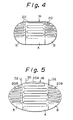
- Figures 4 and 5 show second and third embodiments of the invention respectively.
- the cross-sectional configuration of the system be an oval or elliptic cross section, for an easier mounting thereof.
- the cooling effect is poor even at the outer circumferential portions.
- the cooling effect is substantial not only at the outer circumferential portions but also at the portion near the central position, to possibly cause a remaining of unburnt particulates.
- the heating wires 20A and 20B are arranged in a pattern such that a higher power efficiency is provided at both end portions B of the longer axes than that at the central portion A.
- a wiring pattern With such a wiring pattern, the problem of unburnt particulates at the end portions B of the longer axes does not arise.
- the temperature gradient between the portions A and B can be reduced, to prevent a destruction of the filter due to a substantial thermal distortion thereof.
- the heating wire 20A in the central portion A must extend across the outer circumferential portion B, and thus an intervention between the heating wires 20A and 20B, such as an insulation, is required.
- the lead wires 30 and 32 can be directly extracted, the wiring is simplified.
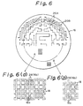
- Figure 6 shows the fourth embodiment of the particulate trap system according to the present invention, in which the plugging pattern for determining the arrangement of the upstream side passages 16a opening toward the upstream and the downstream side passages 16b opening toward the downstream is different at the central portion A and the outer circumferential portion B, to thus provide different particulate trapping performances therebetween.
- the patterns of the heating wires are adapted to the plugging pattern.
- the plugs 28 are provided for every other passage as shown in Fig. 6(b), for arranging the upstream side passages 16a and the downstream side passages 16b.
- the plugs 28 are provided for every four passages as shown in Fig. 6(a), to reduce the surface area of the porous partition 18 used for trapping the particulate. Also, to ensure a complete burning of the large amount of particulates collected in the outer circumferential portion B, a higher density of the heating wire 20B is arranged as shown in Fig. 6, and the heating wires 20A are arranged in the central portion A at the lower density. Such an arrangement of the heating wires enables a good combustibility and propagation of the combustion to be obtained.
- the present invention can be applied to any particulate trapping filter 16, such as a known ceramic foam filter, a filter composed of steel wool coated by a porous alumina layer, or the like.
Landscapes
- Engineering & Computer Science (AREA)
- Chemical & Material Sciences (AREA)
- Combustion & Propulsion (AREA)
- Mechanical Engineering (AREA)
- General Engineering & Computer Science (AREA)
- Processes For Solid Components From Exhaust (AREA)
Description
- The present invention relates to an exhaust gas purification system for trapping carbon and other particulates in an exhaust gas of a diesel engine. More particularly, the invention relates to a particulate trap system for an exhaust gas, by which a filter for trapping particulates, such as a ceramic filter, can be regenerated.
- In an exhaust passage of a diesel engine, an exhaust gas purification system or an emission control system is provided for trapping particulates, such as carbon particles and so forth, as an anti-pollution measure.
- From document US-A-4 516 993, a carbon particulates cleaning device is known, wherein carbon particulates contained in exhaust gases of an internal combustion engine are collected and burnt off by use of an electric heater provided on the upstream end surface of a heat resistant filter member. The electric heater comprises a plurality of heating resistors, to which current is supplied successively in an order depending on a power density thereof. In this manner, the burning of particulates is distributed in time to respective heating areas, thereby varying the exhaust gas flow through the respective heating areas and the cooling effect involved therein.
- A further example of an exhaust gas purification system is illustrated in Fig. 7.
- In Fig. 7, a
particulate trap system 14 is connected to anexhaust pipe 12 of adiesel engine 10, and aparticulate trap filter 16 is disposed inside theparticulate trap system 14. Theparticulate trap filter 16 is formed as a porous ceramic cylinder having a honeycomb structure, and defines a plurality ofupstream side passages 16a anddownstream side passages 16b separated byporous partitions 18, as shown in Fig. 8. The downstream ends and the upstream ends of theupstream side passages 16a, and thedownstream side passages 16b, are closed respectively, and accordingly, the exhaust gas from thediesel engine 10 flows into thepurification system 14 through upstream side open ends of theupstream side passages 16a. The gaseous component of the exhaust gas then passes through the porous structure of theporous partitions 18 into the adjacentdownstream side passages 16b, and is then subsequently discharged. The particulates, such as carbon particles, contained in the exhaust gas are blocked by thepartition 18, and thus are trapped and accumulated in theupstream side passages 16a. - Nevertheless, an increase of the amount of accumulated particulates causes an increase in the resistance to the exhaust gas flow, to thus increase the pressure difference △p between the upstream end and the downstream end of the
particulate trap filter 16, which may lower the output of theengine 10. Therefore, it is necessary to periodically remove the accumulated particulates, and accordingly, anelectronic heater 20 is provided on the upstream side wall surface, for heating and burning the trapped particulates, to thereby regenerate the particulate trap filter. - In Figs. 7 and 8, 22 denotes a filter casing forming the outer shell of the
purification system purification system - During the regeneration process, heat generated by the burning of the particulates in the vicinity of the outer periphery of the
particulate trap filter 16 can escape to the atmosphere, through thefilter casing 22, and this can cause a lowering of the temperature of the particulates to lower than the burning temperature thereof, and thus unburnt particulates remain and the regeneration treatment is only partially successful. - Figure 9 shows local temperature variations during the regeneration treatment, to represent the above-mentioned condition of remaining unburnt particulate. In Fig. 9, the solid line shows temperature variations according to a processing time at the center portion A of the particulate trap filter 16 (for example, in the region A in Fig. 8), and the broken line shows temperature variations according to the processing time at the outer circumferential portion B away from the center (for example, at the region B in Fig. 8). Due to the increase in the difference (temperature difference ΔT₁) between the peak values of the two curves, the amount of unburnt particulates at the outer circumferential portion B is increased. Also, when the temperature at the central portion A of the
filter 16 becomes much higher than that at the outer circumferential portion B, the filter may be destroyed by a substantial thermal distortion thereof. - Therefore, an object of the present invention is to provide a regenerative particulate trap system for an exhaust gas, by which the above-mentioned problems in the prior art are solved and an effective regeneration over the whole area of a particulate trap filter is obtained by preventing an incomplete regeneration due to the outer circumferential portion thereof.
- Another object of the present invention is to reduce the temperature gradient between the center portion and the outer circumferential portion of the particulate trap filter, and thus prevent a destruction of the filter due to an excessive thermal distortion thereof.
- A further object of the present invention is to reduce the electric power consumed by an electric heater used for the regeneration of the particulate trap filter, to thus reduce the load on a power source such as a battery.
- The aforesaid and other objects are accomplished by a particulate trap system for an exhaust emission control, comprising a particulate trap filter disposed within a path for the exhaust gas of an engine for trapping particulates carried by the exhaust gas of the engine; and an electric heater arranged at an upstream end surface of said particulate trap filter for removing accumulated particulates by burning same; characterized in that in a particulate trap filter having a circular end face said electric heater is arranged in a predetermined pattern such that a power efficiency provided for an outer circumferential portion off a central position and peripheral to a central portion of said particulate trap filter is higher than the power efficiency provided for said central portion, or in a particulate trap filter having an oval or elliptic end face said electric heater is arranged in a predetermined pattern such that a higher power efficiency is provided at both end portions of the longer axes than at the central portion.
- According to this aspect, the particulate trap system for an exhaust gas includes an electric heater for burning particulates accumulated in a particulate trap filter. The electric heater is arranged in such a manner that it provides a higher power efficiency at a portion away from the center of the trap filter relative to that at a portion close to the center.
- In a preferred construction, the portion of the electric heater having a higher power efficiency includes sections of heating wire buried in plugs, for defining the exhaust gas flow path, and the portion of the electric heater having the lower power efficiency includes sections of the heating wire which are bent and inserted to the inlet portion of the exhaust gas flow path.
- The particulate trap filter may have a circular end face, in which the portion of the filter located away from the center and having the portion of the electric heater providing a higher power efficiency, and the portion of the filter located at the center and having the portion of the electric heater providing a lower power efficiency are arranged in an essentially concentric manner. Alternatively, the particulate trap filter may have an oval or elliptic end face configuration, in which the portion of the filter having portions of the electric heater providing a higher power efficiency are located at both ends along the longer axis of the filter, and the portion of the filter having the portion of the electric heater providing a lower power efficiency is located therebetween.
- In another preferred construction, the particulate trap filter may be provided with a higher particulate trapping efficiency at the portion away from the center, and a lower particulate trapping efficiency at the central position, by rarying the patterns used for closing the passage by the plug.
- Moreover, according to the present invention, by arranging the electric heater in a pattern as set forth hereinafter, a greater heat energy can be provided at the outer peripheral portion, from which the heat can easily escape, to ensure and maintain the burning of the particulates,to thereby fully regenerate the filter.
- Further, the central portion can maintain the heat and does therefore not require a large heat capacity to maintain the burning of the particulates, so that the amount of heat generated is limited by providing a lower power efficiency to thus reduce the power consumption and to prevent overheating.
- Accordingly, since the temperature at the outer circumferential portion becomes higher to thereby reduce the temperature gradient between that portion and the central portion, the possibility of a destruction of the filter due to a large thermal distortion can be successfully avoided.
- The present invention will be more fully understood from the detailed description given herebelow, and from the accompanying drawings of the preferred embodiments of the invention.
- In the drawings:
- Figs. 1 and 2 show a first embodiment of a particulate trap system for an exhaust gas according to the present invention; Fig. 1 is a diagram showing a pattern of an arrangement of a heater in a particular trap filter having a circular configuration, and Fig. 2 shows a practical arrangement of the heater, by partially enlarged perspective views shown in Figs. (a) and (b);
- Fig. 3 is a view similar to Figs. 2(a) and 2(b), but shows an undesirable arrangement of the heater;
- Figs. 4 and 5 are diagrams showing heater patterns according to second and third embodiments of the invention;
- Fig. 6 is a partial enlarged perspective view of an upstream end portion of the trap filter in a fourth embodiment of the invention, in which the heater arrangement patterns are shown on an enlarged scale in Fig. (a) and (b);
- Figs. 7 and 8 show the prior art; Fig. 7 shows the overall construction of an engine and an exhaust system thereof, and Fig. 8 is a longitudinal section view of the trap filter;
- Fig. 9 is a graph showing time dependent variations of the temperatures in the filter during the regenerating treatment; and
- Figs. 10 and 11 show partial enlarged perspective views of upstream end portions of the trap filters in other embodiments of the invention.
- Referring to the drawings, Figs. 1 and 2 show the first embodiment of a particulate trap system for an exhaust gas according to the present invention. In the shown embodiment, a
particulate trap filter 16 having a circular cross-section is employed, and anelectric heater 20 is provided on the upstream end face C of thefilter 16. As seen, the density of the heating wires of theelectric heater 20 is different at different portions of thefilter 16, to thereby differentiate the amount of electric power consumed in each unit area. Namely, in the shown embodiment, a higher density of theheating wires 20B is provided in an outer circumferential portion B defined concentrically to a central portion A, than the density of theheating wires 20A in the central portion. Therefore, the power efficiency at the outer circumferential portion B is higher than that in the central portion A. In practice, as shown in Fig. 2(b), in the outer circumferential portion B,portions 20B' of theheating wire 20B are buried inupstream side plugs 28 used to plug downstream side passages defined in thefilter 16, to provide a higher density. Also, as shown in Fig. 2(a), at the central position A of thefilter 16, theheating wire 20A is fitted along the end face C of thefilter 16. Since theheating wire 20A covers a wider area than that of an equivalent length of theheating wire 20B, the power consumed (equivalent to the amount of heat generated) at the unit area of the end face of the filter C is reduced. In the shown embodiment, theheating wire 20A is provided with V-shaped bent sections 20A' which are engaged with the opening end of upstream side passages, for positioning and fixing theheating wire 20A on the end face of thefilter 16. Preferablysuch bent sections 20A' are provided at the turning portions (portions 20A" in Fig. 1) by bending the turning portions at a right angle and bending the angled corner into the corresponding opening ends. Furthermore, when it is necessary to further firmly fit theheating wire 20A, a heat resistive inorganic bonding material can be filled in the passage to bond thebent sections 20A'. In this case, the upstream side passages to which the bond is filled will be blocked and will not function as a filter. Nevertheless, as can be appreciated, because of the large number of upstream side passages formed in thefilter 16, the blocking of some of the passages will not affect the exhaust gas flow or the filtering function of the filter overall . - When the
portions 20A''' of theheating wire 20A are buried in theupstream end plug 28 of the downstream side passage, in the same way as theheating wire 20B, the pitch of the wiring pattern must be wider than that of theheating wire 20B to provide a lower power efficiency. In this case, the wiring pattern will become as illustrated in Fig. 3. Here, at the portion A' where theheating wire 20A is not arranged, the accumulated particulates in the vicinity of the upstream end face C are not burnt. (At the downstream portion of thefilter 16, accumulated particulates are burnt, even in thepassage 16a where theheating wire 20A is not arranged, by the heat from adjacent passages.) Therefore, the wiring pattern shown in Fig. 3 is not preferable. Namely, the wiring pattern of theheating wire 20A must be carefully arranged. - It should be noted that, although the construction shown in Fig. 3 is not preferred due to the possibility of remaining unburnt particulates during the regeneration process, an equivalent construction may be applied without causing the defects set out with respect to Fig. 3, when the depth to which the
heating wire 20A is buried is different from that of theheating wire 20B to thus achieve the desired difference in the power efficiency. To realize this, the burying depth of theheating wire 20A at the central portion A must be much less than that of theheating wire 20B in the outer circumferential portion B. Namely, by differentiating the burying depth, the desired difference of the power efficiency can be obtained without changing the pitch of the wiring pattern. - Figures 4 and 5 show second and third embodiments of the invention respectively. When the particulate trap system is mounted below the floor of the vehicle, it may be preferable that the cross-sectional configuration of the system be an oval or elliptic cross section, for an easier mounting thereof. In such a laterally elongated filter configuration, because of a short distance in the shorter axes direction, the cooling effect is poor even at the outer circumferential portions. In contrast, at the portion in the vicinity of the ends of the longer axes, the cooling effect is substantial not only at the outer circumferential portions but also at the portion near the central position, to possibly cause a remaining of unburnt particulates.
- Therefore, in the embodiments of Figs. 4 and 5, the
heating wires - Furthermore, in the first embodiment (Figs. 1 and 2), the
heating wire 20A in the central portion A must extend across the outer circumferential portion B, and thus an intervention between theheating wires lead wires - Figure 6 shows the fourth embodiment of the particulate trap system according to the present invention, in which the plugging pattern for determining the arrangement of the
upstream side passages 16a opening toward the upstream and thedownstream side passages 16b opening toward the downstream is different at the central portion A and the outer circumferential portion B, to thus provide different particulate trapping performances therebetween. In this embodiment, the patterns of the heating wires are adapted to the plugging pattern. Also, in this embodiment, to provide a higher particulate trapping performance for the outer circumferential portion B, theplugs 28 are provided for every other passage as shown in Fig. 6(b), for arranging theupstream side passages 16a and thedownstream side passages 16b. For the central portion A, theplugs 28 are provided for every four passages as shown in Fig. 6(a), to reduce the surface area of theporous partition 18 used for trapping the particulate. Also, to ensure a complete burning of the large amount of particulates collected in the outer circumferential portion B, a higher density of theheating wire 20B is arranged as shown in Fig. 6, and theheating wires 20A are arranged in the central portion A at the lower density. Such an arrangement of the heating wires enables a good combustibility and propagation of the combustion to be obtained. - Note, the present invention can be applied to any
particulate trapping filter 16, such as a known ceramic foam filter, a filter composed of steel wool coated by a porous alumina layer, or the like.
Claims (7)
- A particulate trap system for an exhaust emission control comprisinga particulate trap filter (16) disposed within a path (12) for the exhaust gas of an engine (10) for trapping particulates carried by the exhaust gas of the engine; andan electric heater (20) arranged at an upstream end surface of said particulate trap filter (16) for removing accumulated particulates by burning same;characterized in thatin a particulate trap filter (16) having a circular end face said electric heater (20) is arranged in a predetermined pattern such that a power efficiency provided for an outer circumferential portion (B) off a central position and peripheral to a central portion (A) of said particulate trap filter (16) is higher than the power efficiency provided for said central portion (A), orin a particulate trap filter (16) having an oval or elliptic end face said electric heater (20) is arranged in a predetermined pattern such that a higher power efficiency is provided at both end portions (B) of the longer axes than at the central portion (A).
- A particulate trap system for an exhaust gas according to claim 1, characterized in that a portion (20B) of said electric heater (20) having the higher power efficiency includes sections (20B') of the heating wire buried in plugs (28) defining the exhaust gas flow path (16a, 16b), and a portion (20A) of the electric heater (20) having the lower power efficiency includes sections (20A') of the heating wire bent and inserted into the inlet portion of the exhaust gas flow path (16a).
- A particulate trap system for an exhaust gas according to claim 2, characterized in that said particulate trap filter (16) comprises different exhaust gas passage closing patterns provided by said plugs (28) and arranged to provide a higher particulate trapping performance at said portion (B) off said central portion (A) and a lower particulate trapping performance at said central portion (A).
- A particulate trap system for an exhaust gas according to claim 1, characterized in that in said particulate trap filter (16) having said circular end face said outer circumferential portion (B) having provided the higher power efficiency and said central portion (A) having provided the lower power efficiency are arrangend in an essentially concentric manner.
- A particulate trap system according to one of the preceding claims 1 to 4, characterized in that said particulate trap filter (16) comprisesa plurality of porous partitions (18) disposed in said path (12) for the exhaust gas from said engine (10) which carries particulates, said partitions (18) defining a plurality of exhaust gas passages (16a, 16b) for passing the exhaust gas therethrough;a first plug means (28) for selectively closing one ends of said exhaust gas passages (16b) defined by said partitions (18);a second plug means (28) for selectively closing the other ends of said exhaust gas passages (16a) which are held open at said one ends, to form an exhaust gas path across said porous partitions (18) for trapping said particulates carried by the exhaust gas in said porous partitions (18); and in thatsaid electric heater (20) has portions buried in said first plug means (28) to be fixed on said one ends of said exhaust gas passages for heating and burning out particulates accumulated in said exhaust gas passages, the depths to which said portions of said electric heater (20) are buried being deeper at said portion (B) of the filter off from the center thereof than those at said central portion (A).
- A particulate trap system according to claim 5, characterized in that in said particulate trap filter (16) having said oval or elliptic end face shape said portion of said electric heater (20) buried to a deeper depth is located at both ends of the longer axis of said filter.
- A particulate trap system according to claim 5, characterized in that said electric heater (20) generates a higher heat capacity at said outer circumferential portion (B) off the central portion (A) than at said central portion (A).
Applications Claiming Priority (2)
| Application Number | Priority Date | Filing Date | Title |
|---|---|---|---|
| JP2306084A JPH04179818A (en) | 1990-11-14 | 1990-11-14 | Exhaust gas fine particles purifing device |
| JP306084/90 | 1990-11-14 |
Publications (2)
| Publication Number | Publication Date |
|---|---|
| EP0485974A1 EP0485974A1 (en) | 1992-05-20 |
| EP0485974B1 true EP0485974B1 (en) | 1996-01-24 |
Family
ID=17952840
Family Applications (1)
| Application Number | Title | Priority Date | Filing Date |
|---|---|---|---|
| EP91119334A Expired - Lifetime EP0485974B1 (en) | 1990-11-14 | 1991-11-13 | Regenerative particulate trap system for emission control |
Country Status (4)
| Country | Link |
|---|---|
| US (1) | US5144798A (en) |
| EP (1) | EP0485974B1 (en) |
| JP (1) | JPH04179818A (en) |
| DE (1) | DE69116644T2 (en) |
Families Citing this family (38)
| Publication number | Priority date | Publication date | Assignee | Title |
|---|---|---|---|---|
| DE4132439A1 (en) * | 1991-09-28 | 1993-04-01 | Behr Gmbh & Co | EXHAUST CATALYST |
| DE4209213A1 (en) * | 1992-03-21 | 1993-09-23 | Fev Motorentech Gmbh & Co Kg | FILTER ARRANGEMENT FOR REMOVING SOOT PARTICLES FROM EXHAUST GASES FROM AN INTERNAL COMBUSTION ENGINE |
| US5655212A (en) * | 1993-03-12 | 1997-08-05 | Micropyretics Heaters International, Inc. | Porous membranes |
| EP0658369B1 (en) * | 1993-12-17 | 2000-04-05 | Matsushita Electric Industrial Co., Ltd. | Method for purification of exhaust gas and apparatus used for purification |
| EP0754267B1 (en) * | 1994-04-06 | 1998-07-15 | Minnesota Mining And Manufacturing Company | Electrically regenerable diesel particulate filter cartridge and filter |
| CA2219537A1 (en) * | 1996-10-22 | 1998-04-22 | Masataka Oji | Regenerative heater of diesel engine particulate trap and diesel engine particulate trap using the same heater |
| DE10029978A1 (en) * | 2000-06-26 | 2002-01-10 | Zeuna Staerker Kg | Device for the treatment of diesel exhaust gases |
| DE10105233A1 (en) * | 2001-02-02 | 2002-08-29 | Zeuna Staerker Kg | Device for follow-up treatment of diesel exhaust gases, has heating element preferably in form of glow plug embedded in sleeve with open pores and associated with filter surface |
| DE10106769A1 (en) * | 2001-02-12 | 2002-08-14 | Ego Elektro Geraetebau Gmbh | Filter used for filtering IC engine exhaust gases comprises filter chamber, and filter plates arranged in filter and covering inner cross-sectional area of filter chamber |
| EP1399239B1 (en) | 2001-06-18 | 2005-03-16 | HJS Fahrzeugtechnik GmbH & Co. | Particle filter operating by means of soot combustion and used for diesel engines |
| DE10151425A1 (en) * | 2001-10-18 | 2003-04-30 | Opel Adam Ag | Particle filter for cleaning engine exhaust gases |
| US7238217B2 (en) * | 2004-04-23 | 2007-07-03 | Corning Incorporated | Diesel engine exhaust filters |
| US20090278595A1 (en) * | 2005-07-14 | 2009-11-12 | Braithwaite Sherman W | Braithwaite particle trap (THE BPT) |
| US20080163615A1 (en) * | 2007-01-04 | 2008-07-10 | Trimingham Scott R | Internal combustion engine exhaust filter with pressure relief |
| US7931715B2 (en) * | 2007-02-12 | 2011-04-26 | Gm Global Technology Operations, Inc. | DPF heater attachment mechanisms |
| US7862635B2 (en) * | 2007-02-12 | 2011-01-04 | Gm Global Technology Operations, Inc. | Shielded regeneration heating element for a particulate filter |
| US8388741B2 (en) * | 2007-08-14 | 2013-03-05 | GM Global Technology Operations LLC | Electrically heated particulate filter with reduced stress |
| US8057581B2 (en) * | 2007-08-31 | 2011-11-15 | GM Global Technology Operations LLC | Zoned electrical heater arranged in spaced relationship from particulate filter |
| CN101429888B (en) * | 2007-08-31 | 2013-03-27 | 通用汽车环球科技运作公司 | Zoned electric heater installed in separation relationship with particulate filter |
| US8112990B2 (en) * | 2007-09-14 | 2012-02-14 | GM Global Technology Operations LLC | Low exhaust temperature electrically heated particulate matter filter system |
| US7981198B2 (en) * | 2007-09-14 | 2011-07-19 | GM Global Technology Operations LLC | Overlap zoned electrically heated particulate filter |
| US9140159B2 (en) * | 2007-09-18 | 2015-09-22 | Eugene V. Gonze | High exhaust temperature, zoned, electrically-heated particulate matter filter |
| DE102008050019B4 (en) | 2007-10-04 | 2020-07-09 | GM Global Technology Operations LLC (n. d. Ges. d. Staates Delaware) | System and method for variable power distribution for zone-wise regeneration of an electrically heated particle filter |
| US8146350B2 (en) * | 2007-10-04 | 2012-04-03 | GM Global Technology Operations LLC | Variable power distribution for zoned regeneration of an electrically heated particulate filter |
| US20100095657A1 (en) * | 2008-10-21 | 2010-04-22 | Gm Global Technology Operations, Inc. | Electrically heated diesel particulate filter (dpf) |
| US8584445B2 (en) * | 2009-02-04 | 2013-11-19 | GM Global Technology Operations LLC | Method and system for controlling an electrically heated particulate filter |
| US8950177B2 (en) * | 2009-06-17 | 2015-02-10 | GM Global Technology Operations LLC | Detecting particulate matter load density within a particulate filter |
| US8341945B2 (en) * | 2009-07-01 | 2013-01-01 | GM Global Technology Operations LLC | Electrically heated particulate filter |
| US8479496B2 (en) * | 2009-07-02 | 2013-07-09 | GM Global Technology Operations LLC | Selective catalytic reduction system using electrically heated catalyst |
| US8443590B2 (en) * | 2009-07-02 | 2013-05-21 | GM Global Technology Operations LLC | Reduced volume electrically heated particulate filter |
| US8475574B2 (en) * | 2009-08-05 | 2013-07-02 | GM Global Technology Operations LLC | Electric heater and control system and method for electrically heated particulate filters |
| US8511069B2 (en) * | 2009-08-12 | 2013-08-20 | GM Global Technology Operations LLC | Systems and methods for layered regeneration of a particulate matter filter |
| US8707684B2 (en) | 2010-11-11 | 2014-04-29 | GM Global Technology Operations LLC | Control method and apparatus for regenerating a particulate filter |
| US8505284B2 (en) * | 2011-07-26 | 2013-08-13 | GM Global Technology Operations LLC | Stratified particulate filter regeneration system |
| US8726642B2 (en) * | 2011-11-22 | 2014-05-20 | GM Global Technology Operations LLC | Electrically heated particulate filter restrike methods and systems |
| US10087799B2 (en) * | 2015-07-01 | 2018-10-02 | Denso International America, Inc. | Exhaust device and method of manufacturing an exhaust device with a thermally enhanced substrate |
| FR3094039B1 (en) | 2019-03-21 | 2021-03-19 | Faurecia Systemes Dechappement | Durable heater for vehicle exhaust gas purification device |
| US20210301702A1 (en) | 2020-03-31 | 2021-09-30 | Johnson Matthey Public Limited Company | Exhaust gas joule heater |
Family Cites Families (9)
| Publication number | Priority date | Publication date | Assignee | Title |
|---|---|---|---|---|
| US4373330A (en) * | 1981-06-29 | 1983-02-15 | General Motors Corporation | Diesel engine dual path exhaust cleaner and burner system |
| JPS58106115A (en) * | 1981-12-17 | 1983-06-24 | Nippon Soken Inc | Exhaust gas fine particle purifier having electric heating means |
| JPS58124012A (en) * | 1982-01-19 | 1983-07-23 | Toyota Motor Corp | Trap for particulate in exhaust gas |
| US4512786A (en) * | 1982-04-21 | 1985-04-23 | Mazda Motor Corporation | Exhaust gas purifying device |
| JPS58210310A (en) * | 1982-06-01 | 1983-12-07 | Nippon Denso Co Ltd | Device for removing carbon particles of internal combustion engine |
| JPS5990713A (en) * | 1982-11-17 | 1984-05-25 | Toyota Motor Corp | Fine particles purification device in diesel engine |
| JPS6038018A (en) * | 1983-08-09 | 1985-02-27 | Kazuo Ishii | Multiple perforated surface filter |
| JPS60125715A (en) * | 1983-12-09 | 1985-07-05 | Toyota Motor Corp | Method of treating exhaust gas of diesel engine |
| DE3712333A1 (en) * | 1987-04-11 | 1988-10-20 | Fev Motorentech Gmbh & Co Kg | REGENERATABLE FILTER ARRANGEMENT FOR REMOVING SOOT PARTICLES FROM EXHAUST GASES |
-
1990
- 1990-11-14 JP JP2306084A patent/JPH04179818A/en active Pending
-
1991
- 1991-11-13 EP EP91119334A patent/EP0485974B1/en not_active Expired - Lifetime
- 1991-11-13 US US07/792,200 patent/US5144798A/en not_active Expired - Fee Related
- 1991-11-13 DE DE69116644T patent/DE69116644T2/en not_active Expired - Fee Related
Also Published As
| Publication number | Publication date |
|---|---|
| DE69116644T2 (en) | 1996-06-05 |
| DE69116644D1 (en) | 1996-03-07 |
| EP0485974A1 (en) | 1992-05-20 |
| JPH04179818A (en) | 1992-06-26 |
| US5144798A (en) | 1992-09-08 |
Similar Documents
| Publication | Publication Date | Title |
|---|---|---|
| US5144798A (en) | Regenerative particulate trap system for emission control | |
| EP1450015B1 (en) | Honeycomb filter and exhaust gas purification system | |
| EP0990777B1 (en) | Regeneration system for an exhaust gas cleaning device | |
| US4548625A (en) | Exhaust gas cleaning device for diesel engines | |
| JPH0368210B2 (en) | ||
| JP2707049B2 (en) | Diesel particulate filter | |
| JPS58199018A (en) | Purifying device equipped with electrically heating means for fine particle contained in waste gas | |
| JPS62225221A (en) | Particulates trap | |
| JPH10121941A (en) | Exhaust gas purification device | |
| EP0879938B1 (en) | A device for purifying the exhaust gas of an internal combustion engine | |
| JPH0115684B2 (en) | ||
| JPH03168314A (en) | Cleaning device for exhaust gas particulate | |
| JP3067365B2 (en) | Exhaust gas purification device for internal combustion engine | |
| JP3201114B2 (en) | Exhaust particulate filter for internal combustion engine | |
| JP3401946B2 (en) | Exhaust particulate processing equipment for internal combustion engines | |
| JPH06241022A (en) | Exhaust purification device | |
| JP3064322B2 (en) | Exhaust gas purification device for internal combustion engine | |
| JPH0634570Y2 (en) | Exhaust gas purification device for internal combustion engine | |
| JPH06264722A (en) | Filter device | |
| JPH0430329Y2 (en) | ||
| JP2722854B2 (en) | Exhaust filter for internal combustion engine | |
| JPH0322504Y2 (en) | ||
| JPH04298625A (en) | Filter regeneration device for internal combustion engine | |
| JPH0741859Y2 (en) | Exhaust gas purification device for internal combustion engine | |
| JPH11132027A (en) | Exhaust fine particle control device for internal combustion engine |
Legal Events
| Date | Code | Title | Description |
|---|---|---|---|
| PUAI | Public reference made under article 153(3) epc to a published international application that has entered the european phase |
Free format text: ORIGINAL CODE: 0009012 |
|
| AK | Designated contracting states |
Kind code of ref document: A1 Designated state(s): DE FR GB |
|
| 17P | Request for examination filed |
Effective date: 19920717 |
|
| 17Q | First examination report despatched |
Effective date: 19930804 |
|
| GRAA | (expected) grant |
Free format text: ORIGINAL CODE: 0009210 |
|
| AK | Designated contracting states |
Kind code of ref document: B1 Designated state(s): DE FR GB |
|
| REF | Corresponds to: |
Ref document number: 69116644 Country of ref document: DE Date of ref document: 19960307 |
|
| ET | Fr: translation filed | ||
| PGFP | Annual fee paid to national office [announced via postgrant information from national office to epo] |
Ref country code: GB Payment date: 19961104 Year of fee payment: 6 |
|
| PGFP | Annual fee paid to national office [announced via postgrant information from national office to epo] |
Ref country code: FR Payment date: 19961111 Year of fee payment: 6 |
|
| PGFP | Annual fee paid to national office [announced via postgrant information from national office to epo] |
Ref country code: DE Payment date: 19961122 Year of fee payment: 6 |
|
| PLBE | No opposition filed within time limit |
Free format text: ORIGINAL CODE: 0009261 |
|
| STAA | Information on the status of an ep patent application or granted ep patent |
Free format text: STATUS: NO OPPOSITION FILED WITHIN TIME LIMIT |
|
| 26N | No opposition filed | ||
| REG | Reference to a national code |
Ref country code: GB Ref legal event code: 746 Effective date: 19970901 |
|
| PG25 | Lapsed in a contracting state [announced via postgrant information from national office to epo] |
Ref country code: GB Free format text: LAPSE BECAUSE OF NON-PAYMENT OF DUE FEES Effective date: 19971113 |
|
| PG25 | Lapsed in a contracting state [announced via postgrant information from national office to epo] |
Ref country code: FR Free format text: THE PATENT HAS BEEN ANNULLED BY A DECISION OF A NATIONAL AUTHORITY Effective date: 19971130 |
|
| GBPC | Gb: european patent ceased through non-payment of renewal fee |
Effective date: 19971113 |
|
| PG25 | Lapsed in a contracting state [announced via postgrant information from national office to epo] |
Ref country code: DE Free format text: LAPSE BECAUSE OF NON-PAYMENT OF DUE FEES Effective date: 19980801 |
|
| REG | Reference to a national code |
Ref country code: FR Ref legal event code: ST |