EP0485097A1 - Strap dispensing and accumulating apparatus and combination of same with strapping machine - Google Patents
Strap dispensing and accumulating apparatus and combination of same with strapping machine Download PDFInfo
- Publication number
- EP0485097A1 EP0485097A1 EP91309947A EP91309947A EP0485097A1 EP 0485097 A1 EP0485097 A1 EP 0485097A1 EP 91309947 A EP91309947 A EP 91309947A EP 91309947 A EP91309947 A EP 91309947A EP 0485097 A1 EP0485097 A1 EP 0485097A1
- Authority
- EP
- European Patent Office
- Prior art keywords
- strap
- strapping
- stretch
- out box
- outlet
- Prior art date
- Legal status (The legal status is an assumption and is not a legal conclusion. Google has not performed a legal analysis and makes no representation as to the accuracy of the status listed.)
- Ceased
Links
- 239000000463 material Substances 0.000 claims description 5
- 229920001169 thermoplastic Polymers 0.000 claims description 3
- 239000004416 thermosoftening plastic Substances 0.000 claims description 3
- 230000001419 dependent effect Effects 0.000 claims 1
- 229910000831 Steel Inorganic materials 0.000 description 5
- 239000010959 steel Substances 0.000 description 5
- 229920002635 polyurethane Polymers 0.000 description 4
- 239000004814 polyurethane Substances 0.000 description 4
- 239000004743 Polypropylene Substances 0.000 description 3
- 238000004806 packaging method and process Methods 0.000 description 3
- 229920000728 polyester Polymers 0.000 description 3
- -1 polypropylene Polymers 0.000 description 3
- 229920001155 polypropylene Polymers 0.000 description 3
- 239000012815 thermoplastic material Substances 0.000 description 3
- 210000003811 finger Anatomy 0.000 description 2
- 230000000717 retained effect Effects 0.000 description 2
- 210000003813 thumb Anatomy 0.000 description 2
- 239000012780 transparent material Substances 0.000 description 2
- 229910000975 Carbon steel Inorganic materials 0.000 description 1
- 229910000639 Spring steel Inorganic materials 0.000 description 1
- 239000010962 carbon steel Substances 0.000 description 1
- 238000010586 diagram Methods 0.000 description 1
- 239000011521 glass Substances 0.000 description 1
- 238000012856 packing Methods 0.000 description 1
- 229920000515 polycarbonate Polymers 0.000 description 1
- 239000004417 polycarbonate Substances 0.000 description 1
Images


Classifications
-
- B—PERFORMING OPERATIONS; TRANSPORTING
- B65—CONVEYING; PACKING; STORING; HANDLING THIN OR FILAMENTARY MATERIAL
- B65B—MACHINES, APPARATUS OR DEVICES FOR, OR METHODS OF, PACKAGING ARTICLES OR MATERIALS; UNPACKING
- B65B13/00—Bundling articles
- B65B13/18—Details of, or auxiliary devices used in, bundling machines or bundling tools
- B65B13/184—Strap accumulators
-
- Y—GENERAL TAGGING OF NEW TECHNOLOGICAL DEVELOPMENTS; GENERAL TAGGING OF CROSS-SECTIONAL TECHNOLOGIES SPANNING OVER SEVERAL SECTIONS OF THE IPC; TECHNICAL SUBJECTS COVERED BY FORMER USPC CROSS-REFERENCE ART COLLECTIONS [XRACs] AND DIGESTS
- Y10—TECHNICAL SUBJECTS COVERED BY FORMER USPC
- Y10T—TECHNICAL SUBJECTS COVERED BY FORMER US CLASSIFICATION
- Y10T292/00—Closure fasteners
- Y10T292/08—Bolts
- Y10T292/0911—Hooked end
- Y10T292/0945—Operating means
- Y10T292/0951—Rigid
-
- Y—GENERAL TAGGING OF NEW TECHNOLOGICAL DEVELOPMENTS; GENERAL TAGGING OF CROSS-SECTIONAL TECHNOLOGIES SPANNING OVER SEVERAL SECTIONS OF THE IPC; TECHNICAL SUBJECTS COVERED BY FORMER USPC CROSS-REFERENCE ART COLLECTIONS [XRACs] AND DIGESTS
- Y10—TECHNICAL SUBJECTS COVERED BY FORMER USPC
- Y10T—TECHNICAL SUBJECTS COVERED BY FORMER US CLASSIFICATION
- Y10T292/00—Closure fasteners
- Y10T292/08—Bolts
- Y10T292/1043—Swinging
- Y10T292/1075—Operating means
- Y10T292/1083—Rigid
-
- Y—GENERAL TAGGING OF NEW TECHNOLOGICAL DEVELOPMENTS; GENERAL TAGGING OF CROSS-SECTIONAL TECHNOLOGIES SPANNING OVER SEVERAL SECTIONS OF THE IPC; TECHNICAL SUBJECTS COVERED BY FORMER USPC CROSS-REFERENCE ART COLLECTIONS [XRACs] AND DIGESTS
- Y10—TECHNICAL SUBJECTS COVERED BY FORMER USPC
- Y10T—TECHNICAL SUBJECTS COVERED BY FORMER US CLASSIFICATION
- Y10T403/00—Joints and connections
- Y10T403/60—Biased catch or latch
- Y10T403/608—Pivoted
Definitions
- This invention pertains to strap dispensing and accumulating apparatus and to a combination comprising a strapping machine having a strapping head and such dispensing and accumulating apparatus.
- Strapping machines which include strapping heads, are in widespread use for applying straps of thermoplastic material, such as polyester or polypropylene, in tensioned loops around packages.
- a strapping head of a strapping machine draws portions of a strap of such material in an indeterminate length into the strapping machine and feeds the strap around a package via a strap chute, whereupon the strapping head tensions the strap in a tensioned loop around the package, welds the strap in the tensioned loop, and severs the strap in the tensioned loop from other portions of the strap following the tensioned loop.
- the strapping head draws portions of the strap forwardly into the strapping machine when feeding the strap around the package and draws portions of the strap backwardly by the strapping head from the strapping machine when tensioning the strap.
- a strap accumulator is used to accumulate portions of the strap drawn from a strap dispenser before portions of the strap are drawn by the strapping head into the strapping machine from the strap accumulator, and to accumulate portions of the strap drawn from the strapping machine into the strap accumulator.
- a strap accumulator which may be also called a stretch-out box, is exemplified in Bader, Jr., U.S. Patent No. 4,651,944.
- Other strap accumulators or similar devices are disclosed in Noguchi U.S. Patent No. 3,946,921 and Brenneisen U.S. Patent No. 3,137,426.
- a strap dispensing and accumulating apparatus for use with a strap of thermoplastics material and with a strapping machine having a strapping head operable to draw portions of the strap forwards into the strapping machine and to draw portions of the strap backwards from the strapping machine, the dispensing and accumulating apparatus being useful to accumulate strap portions before those portions are drawn by the strapping head into the strapping machine, to accumulate strap portions drawn by the strapping head from the strapping machine, and to dispense accumulated strap portions of the strap to the strapping head, said dispensing and accumulating apparatus comprises
- Such dispensing and accumulating apparatus can be effectively used with a strap of thermoplastic material, such as polyester or polypropylene, and with a strapping machine of a known type having a strapping head operable at certain times to draw portions of the strap forwardly into the strapping machine and at other times to draw portions of the strap backwardly from the strapping machine.
- the strap accumulator is useful to accumulate portions of the strap before portions of the strap are drawn by the strapping head into the strapping machine, to accumulate portions of the strap drawn by the strapping head from the strapping machine, and to dispense accumulated strap portions to the strapping head.
- the strap guide is an elongate member having two opposite ends and is mounted pivotally between the side walls, near the strap outlet, for pivotal movement about an axis near one of its opposite ends.
- the strap guide is pivotable, therefore, between the upper and lower positions.
- such dispensing and accumulating apparatus comprises a device for holding the strap guide releasably in the upper position.
- the holding device may be a magnetic device, whereupon one of the side walls may have an aperture enabling a user manually to release the strap guide from the raised position, as by inserting his or her finger or a small tool.
- the feeding mechanism may be arranged to be selectively actuated and deactuated, whereupon the apparatus may further comprise a device, such as a photoelectric device, for detecting when a strap accumulating in the stretch-out box has reached a predetermined level above the strap guide in the upper position, and for deactuating the feeding mechanism temporarily when the detecting device has detected that the accumulating strap has reached the predetermined level. It is preferred that the feeding mechanism is arranged to feed the strap into the stretch-out box at a rate not less and preferably greater than the rate at which the strapping head draws the strap from the stretch-out box.
- the feeding mechanism comprises a pair of strap-feeding rollers arranged to engage a strap in a driving relationship with the strap and means for moving one of the rollers temporarily when it is desired to insert a strap between the rollers.
- such dispensing and accumulating apparatus may comprise an elongate, flexible, polymeric chute connected to the stretch-out box, near the strap outlet.
- the flexible chute is adapted to guide a strap between the strap outlet and a strapping machine of the type noted above.
- dispensing and accumulating apparatus can be effectively used to thread a strap into the strapping head of a strapping machine of the type noted above, whereby such apparatus may be conveniently described as "self-threading" apparatus.
- the feeding mechanism is actuated to feed the strap from a supply of the strap in an indeterminate length through the channel defined by the strap guide and the lower wall, along with the side walls, and through the flexible chute, into the strapping head.
- the strap is arrested at its leading end and begins to accumulate in the stretch-out box.
- the strap accumulating in the stretch-out box pivots the strap guide from its lower position toward its upper position.
- the holding device holds the strap guide releasably in its upper position.
- the detecting device deactuates the feeding mechanism temporarily.
- the strapping head draws accumulated portions of the strap from the stretch-out box.
- the detecting device no longer deactuates the feeding mechanism, which feeds a further quantity of the strap into the stretch-out box.
- the strap guide continues to be releasably held in its upper position. Since the feeding mechanism is arranged to feed the strap into the stretch-out box at a greater rate compared to the rate at which the strapping head draws the strap from the stretch-out box, the feeding mechanism feeds the strap into the stretch-out box until the strap accumulating in the stretch-out box again reaches the predetermined level, whereupon the detecting device again deactuates the feeding mechanism temporarily.
- the strapping head tensions the strap
- the strapping head draws portions of the strap backwardly into the stretch-out box, in which the strap drawn backwardly into the stretch-out box accumulates, along with the strap fed into the stretch-out box by the feeding mechanism.
- strap dispensing and accumulating apparatus which may be otherwise similar in other respects to strap dispensing and accumulating apparatus described above, may comprise a strap snubber mounted to the stretch-out box, near the strap outlet.
- the strap snubber is adapted to impart frictional resistance to a strap passing through the strap outlet.
- the strap snubber is adjustable so as to impart adjustable levels of frictional resistance to a strap passing through the strap outlet.
- Such dispensing and accumulating apparatus may be advantageously combined with a strapping machine of the type noted above, in a strapping system, particularly but not exclusively if such feeding and accumulating apparatus comprises a flexible chute, as described above.
- the flexible chute has an inlet end connected to the stretch-out box, near the strap outlet, and an outlet end.
- a bracket and a latch are used for connecting the outlet end of the flexible chute to the strapping head.
- the bracket is mounted to the strapping head.
- the latch is movable between an opened position and a closed position and is adapted to latch the outlet end of the flexible chute to the bracket when moved to the closed position.
- the outlet end of the flexible chute has at least one recess and at least one of the bracket and the latch is shaped so as to fit into the recess when the latch is moved to the closed position.
- the outlet end of the flexible chute has two such recesses, the bracket being shaped so as to fit into one such recess and the latch being shaped so as to fit into the other recess.
- strap dispensing and accumulating apparatus 10 constitutes a preferred embodiment of this invention.
- the apparatus 10 utilizes a strap S of thermoplastic material, such as a polyester strap or a polypropylene strap, which is preferred.
- SIGNODETM CONTRAXTM strap as available commercially from Signode Industry Packing Systems, supra , is preferred.
- the strap S is supplied to the apparatus by and from a strap dispenser 12 including a supply reel 14, which holds a supply of the strap S in an indeterminate length, over a direction-changing roller 16.
- the strap dispenser 12 has spaced, pivotally mounted levers 18 enabling the supply reel 14 to be selectively pivoted between an operative position and an inoperative position.
- the supply reel 14 is shown, in Figure 4, in the operative position in full lines and in the inoperative position in phantom lines. The supply reel 14 can be thus pivoted to the inoperative position when it is necessary to replace the supply reel 14 after the supply of the strap S on the supply reel 14 has been exhausted.
- the strap dispenser 14 may be a SIGNODETM Model DF-12D dispenser, as available commercially from Signode Industry Packaging Systems, supra .
- the strap S is supplied by and from the apparatus 10 to a strapping machine M including a strapping head 20, which is shown fragmentarily in Figures 1 and 2, of a known type. Except for certain elements of the strapping head 20, the strapping machine M is not shown.
- the strapping head 20 has two feeding rollers 22 and two tensioning or take-up rollers 24. When driven by the strapping head 20 in a known manner, the feeding rollers 22 draw the strap S forwardly at a given rate into the strapping machine M from the apparatus 10.
- the feeding rollers 22 are arranged to be selectively disengaged from the strap S , in a known manner, so as to enable the strap S to be drawn backwardly by the tensioning rollers 24.
- the tensioning rollers 24 draw the strap S backwardly at a similar rate from the strapping machine M into the apparatus 10.
- the tensioning rollers 24 are arranged to be selectively disengaged from the strap S , in a known manner, so as to enable the strap S to be drawn forwardly by the feeding rollers 22.
- the strapping head 20 is operable, in a known manner, to feed the strap S around a package (not shown) via a strap chute (not shown) when the feeding rollers 22 are driven with the tensioning rollers 24 disengaged from the strap S .
- the strapping head 20 is operable, in a known manner, to tension the strap S in a tensioned loop around the package when the tensioning rollers 24 are driven with the feeding rollers 22 disengaged from the strap S .
- the strapping head 20 is operable in a known manner, to weld the strap S in the tensioned loop around the package and to sever the strap S in the tensioned loop from those portions of the strap S following the tensioned loop.
- the strapping machine M including the strapping head 20 may be a SIGNODETM SPIRITTM Model BCU strapping machine including a SIGNODETM SPIRITTM strapping head, as available commercially from Signode Industry Packaging Systems, supra .
- the apparatus 10 comprises a stretch-out box 30 having an end wall 32 defining a strap inlet 34 and an end wall 36 defining a strap outlet 38. Also, the stretch-out box 30 has a lower wall 40 defining a guiding surface 42, an upper wall 44, and two side walls 46, 48, in parallel relation to each other. So as to enable a user to observe the strap S and other elements in the stretch-out box 30, one of the side walls, namely the side wall 46, is made of a transparent material, such as glass or polycarbonate, which is preferred. The distance between the side walls 46, 48, is slightly greater than the width of the strap S .
- the guiding surface 42 is arched, as shown, and extends between a lower edge of the strap inlet 34 and a lower edge of the strap outlet 38.
- the apparatus 10 comprises an elongate, substantially rigid strap guide 60 having two opposite ends 62, 64, which are rounded, as shown.
- the strap guide 60 is mounted pivotally between the side walls 46, 48, near the strap outlet 38, via a pivot pin 66 extending through the strap guide 60, near the strap guide end 62, and defining an axis, about which the strap guide 60 is pivotable.
- the strap guide 60 is pivotable between an upper, inoperative position, in which it is shown in phantom lines in Figure 1 and in full lines in Figure 8, and a lower, operative position, in which it is shown in full lines in Figure 1.
- the strap guide 60 is biased gravitationally toward the lower position.
- the end wall 36 defining the strap outlet 38 is made of a magnetizable material, such as carbon steel, which is preferred.
- a permanent magnet 70 is mounted via screws (not shown) in a recess 72 in the strap guide 60.
- the permanent magnet 70 coacts with the end wall 36 to hold the strap guide 60 releasably in the upper position.
- the side wall 46 made of a transparent material has an aperture 74 (see Figure 1) enabling a user manually to release the strap guide 60 from the upper position, by inserting one of his or her fingers or a small tool (not shown) and pushing the strap guide 60 so as to separate the permanent magnet 70 from the end wall 36.
- the strap guide 60 tends to pivot toward the lower position after it has been released from the upper position.
- the strap guide 60 has a guiding surface 80, which is its lower surface when it is in its lower position.
- the guiding surface 80 conforms to the guiding surface 42 of the lower wall 40 and overlies such surface 42 in the lower position of the strap guide 60.
- the strap guide 60 coacts with the lower wall 40, along with the side walls 46, 48, to define a channel between the guiding surface 80 of the strap guide 60 and the guiding surface 42 of the lower wall 40, and between the side walls 46, 48, for guiding the strap S when the strap S is fed into the stretch-out box 30, via the strap outlet 38.
- the strap S is guided, in the channel defined thereby, from the strap inlet 34 to the strap outlet 38.
- the apparatus 10 comprises a mechanism 90 for feeding the strap S from the strap dispenser 12, over the direction-changing roller 16, into the stretch-out box 30, via the strap inlet 34.
- the feeding mechanism 90 is arranged to feed the strap S into the stretch-out box 30 at a faster rate compared to the given rate at which the strapping head 20 draws the strap S from the stretch-out box 30.
- the mechanism 90 comprises a base 92, on which a fractional horsepower, alternating-current motor 94 is mounted.
- the motor 94 has a shaft 96, which is driven by the motor 94, and to which a shaft 98 is coupled for conjoint rotation, via a coupler 100.
- a polyurethane-coated roller 102 having a strap groove 104 is mounted on the roller shaft 98 for conjoint rotation, via a key 106 fitting into keyways in the roller 102 and in the shaft 98.
- the strap groove 104 accommodates the strap S engaging the roller 102.
- the shaft 98 extends through aligned apertures 108, 110, in two upright plates 112, 114, and is journalled in annular bearings 116, 118, which are mounted in the aligned apertures 108, 110.
- the upright plates 112, 114 are mounted via screws 120, to a bracket 122, which is mounted to the base 92.
- a steel roller 130 is journalled on a shaft 132, via a roller bearing 134, which is mounted within the roller 130 and around the shaft 132.
- the shaft 132 extends through an aperture 136 in the upright plate 112 and through an aperture 138 in the upright plate 114.
- the apertures 136, 138 are shaped so as to permit the shaft 132 to translate freely in the apertures 136, 138, and so as to permit the shaft 132 to be vertically displaced between an upper position and a lower position.
- the shaft 132 is shown in its lower position in Figure 7 and in an intermediate position in Figures 5 and 6.
- the steel roller 130 fits loosely into the strap groove 104 of the polyurethane-coated roller 102 and overlies the strap S in the strap groove 104.
- the shaft 132 is biased toward its lower position by two coiled springs 142, 144, which bear against the shaft 132, near its opposite ends 146, 148.
- the coiled spring 142 is retained, at its upper end, in a socket 150 opening downwardly in a block 152, which is mounted to the upright plate 112 by screws 153.
- the coiled spring 144 is retained, at its upper end, in a socket 154 opening downwardly in a block 158, which is mounted to the upright plate 114 by screws 160.
- a pair of manually actuatable levers 170, 172 are provided, which enable a user to raise the shaft 132 temporarily from its lower position.
- the lever 170 mounted pivotally to the upright plate 112, via a pivot pin (not shown) so as to engage the shaft 132 between the coiled spring 142 and the upright plate 112.
- the lever 172 is mounted pivotally to the upright plate 114, via a pivot pin 176, so as to engage the shaft 132 between the coiled spring 144 and the upright plate 114.
- the levers 170, 172 are connected by a rod 178.
- the rod 178 is arranged to engage a flanged plate 180, which is mounted to the upright plates 112, 114, so as to limit pivotal movement of the levers 170, 172, in each direction.
- Strap-guiding blocks 182, 184 which are mounted between the upright plates 112, 114, in front of the rollers 102, 130, define a narrow passage, which facilitates threading the strap S initially into the mechanism 90 from the strap dispenser 12.
- An elongate, flexible chute 200 having an inlet end 202 and an outlet end 204 and comprising an elongate, flexible, polymeric tube, which is flattened so as to have an oblong cross-section shown in Figure 3, is connected between the stretch-out box 30 and the strapping machine 20.
- the inlet end 202 of the chute 200 is connected via shoulder bolts 206 to a bracket 208, which is mounted to the stretch-out box 30, near the strap outlet 38.
- the outlet end 204 of chute 200 is connected to the strapping machine 20, via a bracket 212 and a latch 214.
- the chute 200 is connected so as to guide the strap S when the strap S is drawn by the feeding rollers 22 forwardly into the strapping machine 20 from the stretch-out box 30 and when the strap S is drawn by the tensioning rollers 24 backwardly into the stretch-out box 30 from the strapping machine 20.
- the bracket 212 is mounted to the strapping machine 20, near the feeding rollers 22.
- the inlet end 202 of the chute 200 has two triangular recesses 216, 218, as shown in Figure 2.
- the triangular recess 216 accommodates a triangular flange 220, which is provided on the bracket 216, and the triangular recess 218 accommodates a triangular portion 222 of the latch 214.
- the latch 214 is mounted pivotally to the bracket 212, via a pivot pin 220 fitting into an elongate slot 222 in the bracket 212.
- the elongate slot 222 enables the pivot pin 220 to be adjustably located.
- the latch 214 is mounted for pivotal movement between a closed position and an opened position.
- the latch 214 is shown, in Figure 2, in its closed position in full lines and in its opened position in phantom lines.
- a thumb screw 226, which is carried by the latch 214, is arranged to be manually turned in a clockwise direction (as shown) until it bears against the bracket 212, in the closed position of the latch 214, when it is desired to latch the outlet end 204 of the chute 200 to the bracket 212.
- the thumb screw 226 is arranged to be oppositely turned when it is desired to pivot the latch 214 to the opened position so as to release the outlet end 204 of the chute 200 from the bracket 212.
- a photoelectric cell 230 is mounted to the end wall 32, near the upper wall 44, so as to be enclosed within the stretch-out box 30.
- a reflector 232 is mounted to the end wall 34, near the upper wall 44, in opposed relation to the photoelectric cell 230.
- the photoelectric cell 230 is operable in a known manner to transmit a beam toward the reflector 232, at a predetermined level above the strap guide 60 in the upper position, and to receive the beam, as reflected by the reflector 232, unless the beam is interrupted by the strap S in the stretch-out box 230. Because the strap guide 60 is below the beam level when the strap guide 60 is in the upper position, the strap guide 60 does not interrupt the beam.
- the photoelectric cell 230 is arranged in a known manner to control a pair of contacts 234 in such manner that the contacts 234 are closed except when the beam is interrupted and in such manner that the contacts 234 are opened when the beam is interrupted.
- a manually actuatable, push-to-close, pull-to-open switch 240 is mounted to the side wall 46, near the upper wall 44, and is connected via a fuse 242 (see Figure 9) to a source of electrical power.
- a running lamp 244 is connected to the switch 240 so as to indicate when the switch 240 is closed.
- the motor 94 is connected to the switch 240, via a pair of contacts 246, which are controlled by a relay 248.
- the relay 248 is connected to the switch 240, via the contacts 234 controlled by the photoelectric cell 230. Consequently, the motor 94 is enabled when the switch 240 is closed, unless the contacts 234 are opened by the photoelectric cell 230.
- such dispensing and accumulating apparatus can be effectively used to thread the strap S from the strap dispenser 12 into the strapping head 20 of the strapping machine M .
- the strap guide 60 is pivoted to its lower position.
- the levers 170, 172 are operated manually to raise the shaft 132 temporarily from its lower position, the strap S is inserted, at its leading end, into the strap groove 104 of the polyurethane-coated roller 102 and below the steel roller 130, and the levers 170, 172, are released so that the strap S is pressed tightly in the strap groove 104 by the steel roller 130, which is biased by the coiled springs 142, 144, bearing against the shaft 132.
- the switch 240 is pressed, so as to actuate the motor 94 of the feeding mechanism 90.
- the motor 94 is actuated, the polyurethane-coated roller 102 is driven and coacts with the steel roller 130 to feed the strap S through the channel defined by the strap guide 60 and the lower wall 40, along with the side walls 46, 48, and through the flexible chute 200, into the strapping head 20.
- the feeding rollers 22 and the tensioning rollers 24 are disengaged, so as to permit the strap S to be further fed into the strapping head 20.
- the strap S When the strap S being fed into the strapping head 20 encounters sufficient resistance, the strap S is arrested at its leading end and begins to accumulate in the stretch-out box 30.
- the strap S accumulating in the stretch-out box 30 pivots the strap guide 60 from its lower position toward its upper position.
- the photoelectric cell 230 opens the contacts 234 so as to deactuate the motor 94 of the feeding mechanism 90 temporarily.
- the feeding rollers 22 of the strapping head 20 are engaged with the strap S and are driven so as to draw accumulated portions of the strap S from the stretch-out box 30 into the strapping head 20.
- the tensioning rollers 24 are disengaged from the strap S when the strap S is drawn into the strapping head 20.
- the photoelectric cell 230 closes the contacts 234 so as to enable the motor 94 of the feeding mechanism 90 to be again actuated, whereupon the feeding mechanism 90 feeds a further quantity of the strap S into the stretch-out box 30.
- the feeding mechanism 90 Since the feeding mechanism 90 is arranged to feed the strap S into the stretch-out box 30 at a faster rate compared to the given rate at which the strapping head 20 draws the strap S from the stretch-out box 30, the feeding mechanism 90 feeds the strap S into the stretch-out box 30 until the strap S accumulating in the stretch-out box 30 again reaches the predetermined level at which the strap S interrupts the beam emitted by the photoelectric cell 230 and reflected by the reflector 232, whereupon the photoelectric cell 230 again opens the contacts 234 so as to deactuate the motor 94 of the feeding mechanism 90 temporarily.
- the tensioning rollers 24 of the strapping head 20 are engaged with the strap S and are driven so as to draw an excess quantity of the strap S from the strapping head 20 into the stretch-out box 30.
- the feeding rollers 22 are disengaged from the strap S when the strap S is drawn from the strapping head 20.
- the strap S drawn from the strapping head 20 into the stretch-out box 30 accumulates in the stretch-out box 30, along with the strap S fed into the stretch-out box 30 by the feeding mechanism 90, as controlled by the photoelectric cell 230.
- the flexible chute 200 is omitted and the apparatus 10 is provided with a strap snubber 250, which is not used in the preferred embodiment.
- the strap snubber 250 is mounted on a bracket 252, which is mounted to the stretch-out box 30, near the strap outlet 38.
- the bracket 252 includes upper plate 254 defining a guiding surface 256, which is the upper surface of the upper plate 254.
- the strap snubber 250 comprises a bracket 260 having a top wall 262, and having two side walls 264, 266. Also, the strap snubber 250 comprises a blade 270, which is made of spring steel. The blade 270 is shaped, as shown, so as to define a mounting portion 272, a curved portion 274, and a distal portion 276. The mounting portion 272 overlies the top wall 262 and is mounted to the top wall 262 via screws 278. The curved portion 274 is disposed so as to press a portion of the strap S against the guiding surface 256 of the bracket 252, so as to impart frictional resistance to the strap S passing in either direction through the strap outlet 38. The distal portion 276 extends beneath the top wall 262.
- An adjusting screw 280 having a nut 282 threaded thereon is threaded through a threaded aperture 284 in the top wall 262, so as to bear against the distal portion 276.
- the adjusting screw 280 may be manually adjusted to different positions, in which the adjusting screw 280 may be then secured by the nut 282, so that the blade 270 can impart adjustable levels of frictional resistance to the strap S passing in either direction through the strap outlet 38.
Landscapes
- Engineering & Computer Science (AREA)
- Mechanical Engineering (AREA)
- Basic Packing Technique (AREA)
Abstract
A strap dispensing and accumulating apparatus (70) includes a device (90) for feeding strap (S) from a supply (14) to a strapping machine (M) and an accumulator for accumulating strap being fed forwards from the supply (14) or being pushed backwards by the strapping machine (M). The accumulator includes a stretch-out box (30) having an inlet (34), an outlet (36), and a lower wall (40). When pivoted to one position, an strap guide (60) coacts with the lower wall (40), and with other elements, to define a channel for strap between the inlet (34) and the outlet (36). A detecting device (230) is arranged to deactuate the feeding device (90) when strap accumulating in the stretch-out box (30) reaches a predetermined level. A flexible chute (200) guides strap from the outlet (36) to a strapping head (M) of a strapping machine. A combination of such apparatus with a strapping machine having a strapping head is disclosed.
Description
- This invention pertains to strap dispensing and accumulating apparatus and to a combination comprising a strapping machine having a strapping head and such dispensing and accumulating apparatus.
- Strapping machines, which include strapping heads, are in widespread use for applying straps of thermoplastic material, such as polyester or polypropylene, in tensioned loops around packages. Typically, a strapping head of a strapping machine draws portions of a strap of such material in an indeterminate length into the strapping machine and feeds the strap around a package via a strap chute, whereupon the strapping head tensions the strap in a tensioned loop around the package, welds the strap in the tensioned loop, and severs the strap in the tensioned loop from other portions of the strap following the tensioned loop. Well known models of such strapping machines having such strapping heads are available commercially from Signode Industry Packaging Systems (a division of Illinois Tool Works Inc.) of Glenview, Illinois under its SIGNODE™ trademark, as exemplified by SIGNODE™ SPIRIT™ strapping machines.
- Typically, the strapping head draws portions of the strap forwardly into the strapping machine when feeding the strap around the package and draws portions of the strap backwardly by the strapping head from the strapping machine when tensioning the strap. Commonly, a strap accumulator is used to accumulate portions of the strap drawn from a strap dispenser before portions of the strap are drawn by the strapping head into the strapping machine from the strap accumulator, and to accumulate portions of the strap drawn from the strapping machine into the strap accumulator.
- A strap accumulator, which may be also called a stretch-out box, is exemplified in Bader, Jr., U.S. Patent No. 4,651,944. Other strap accumulators or similar devices are disclosed in Noguchi U.S. Patent No. 3,946,921 and Brenneisen U.S. Patent No. 3,137,426.
- There has been a need, to which this invention is addressed, for improvements in strap dispensing and accumulating apparatus, which may be advantageously combined with a strapping machine in a strapping system.
- According to this invention a strap dispensing and accumulating apparatus for use with a strap of thermoplastics material and with a strapping machine having a strapping head operable to draw portions of the strap forwards into the strapping machine and to draw portions of the strap backwards from the strapping machine, the dispensing and accumulating apparatus being useful to accumulate strap portions before those portions are drawn by the strapping head into the strapping machine, to accumulate strap portions drawn by the strapping head from the strapping machine, and to dispense accumulated strap portions of the strap to the strapping head, said dispensing and accumulating apparatus comprises
- (a) a stretch-out box having a strap inlet and a strap outlet and including two side walls in parallel relation to each other and a lower wall defining a guiding surface between the strap inlet and the strap outlet,
- (b) an strap guide disposed between the side walls and movable between a lower, operative position and an upper, inoperative position, the strap guide having a guiding surface, which overlies the guiding surface of the lower wall in the lower position of the strap guide, and,
- (c) means for feeding a strap from a supply of the strap into the stretch-out box, via the strap inlet,
wherein the strap guide in the lower position constitutes means coacting with the lower wall, along with the side walls, to define a channel between the strap inlet and the strap outlet for guiding a strap being fed into the stretch-out box via the strap inlet. - Such dispensing and accumulating apparatus can be effectively used with a strap of thermoplastic material, such as polyester or polypropylene, and with a strapping machine of a known type having a strapping head operable at certain times to draw portions of the strap forwardly into the strapping machine and at other times to draw portions of the strap backwardly from the strapping machine. Specifically, the strap accumulator is useful to accumulate portions of the strap before portions of the strap are drawn by the strapping head into the strapping machine, to accumulate portions of the strap drawn by the strapping head from the strapping machine, and to dispense accumulated strap portions to the strapping head.
- Preferably, the strap guide is an elongate member having two opposite ends and is mounted pivotally between the side walls, near the strap outlet, for pivotal movement about an axis near one of its opposite ends. The strap guide is pivotable, therefore, between the upper and lower positions. Preferably, moreover, such dispensing and accumulating apparatus comprises a device for holding the strap guide releasably in the upper position. The holding device may be a magnetic device, whereupon one of the side walls may have an aperture enabling a user manually to release the strap guide from the raised position, as by inserting his or her finger or a small tool.
- The feeding mechanism may be arranged to be selectively actuated and deactuated, whereupon the apparatus may further comprise a device, such as a photoelectric device, for detecting when a strap accumulating in the stretch-out box has reached a predetermined level above the strap guide in the upper position, and for deactuating the feeding mechanism temporarily when the detecting device has detected that the accumulating strap has reached the predetermined level. It is preferred that the feeding mechanism is arranged to feed the strap into the stretch-out box at a rate not less and preferably greater than the rate at which the strapping head draws the strap from the stretch-out box.
- Preferably, the feeding mechanism comprises a pair of strap-feeding rollers arranged to engage a strap in a driving relationship with the strap and means for moving one of the rollers temporarily when it is desired to insert a strap between the rollers.
- Additionally, such dispensing and accumulating apparatus may comprise an elongate, flexible, polymeric chute connected to the stretch-out box, near the strap outlet. The flexible chute is adapted to guide a strap between the strap outlet and a strapping machine of the type noted above.
- Accordingly, such dispensing and accumulating apparatus according to a preferred embodiment of this invention can be effectively used to thread a strap into the strapping head of a strapping machine of the type noted above, whereby such apparatus may be conveniently described as "self-threading" apparatus.
- Thus, with the strap guide in its lower position, the feeding mechanism is actuated to feed the strap from a supply of the strap in an indeterminate length through the channel defined by the strap guide and the lower wall, along with the side walls, and through the flexible chute, into the strapping head. When the strap being fed into the strapping head encounters sufficient resistance, the strap is arrested at its leading end and begins to accumulate in the stretch-out box. The strap accumulating in the stretch-out box pivots the strap guide from its lower position toward its upper position. When the strap guide reaches its upper position, the holding device holds the strap guide releasably in its upper position. When the strap accumulating in the stretch-out box reaches the predetermined level, the detecting device deactuates the feeding mechanism temporarily.
- Subsequently, when the strapping machine is operated, the strapping head draws accumulated portions of the strap from the stretch-out box. When the strap accumulated in the stretch-out box no longer reaches the predetermined level, the detecting device no longer deactuates the feeding mechanism, which feeds a further quantity of the strap into the stretch-out box. The strap guide continues to be releasably held in its upper position. Since the feeding mechanism is arranged to feed the strap into the stretch-out box at a greater rate compared to the rate at which the strapping head draws the strap from the stretch-out box, the feeding mechanism feeds the strap into the stretch-out box until the strap accumulating in the stretch-out box again reaches the predetermined level, whereupon the detecting device again deactuates the feeding mechanism temporarily.
- Thereupon, when the strapping head tensions the strap, the strapping head draws portions of the strap backwardly into the stretch-out box, in which the strap drawn backwardly into the stretch-out box accumulates, along with the strap fed into the stretch-out box by the feeding mechanism.
- These operations of such dispensing and accumulating apparatus according to a preferred embodiment of this invention are repeated, as the strapping machine is cycled from package to package, until the supply of the strap has been exhausted. A new supply of a similar strap may be then provided.
- In an alternate embodiment of this invention, strap dispensing and accumulating apparatus, which may be otherwise similar in other respects to strap dispensing and accumulating apparatus described above, may comprise a strap snubber mounted to the stretch-out box, near the strap outlet. The strap snubber is adapted to impart frictional resistance to a strap passing through the strap outlet. Preferably, the strap snubber is adjustable so as to impart adjustable levels of frictional resistance to a strap passing through the strap outlet.
- Such dispensing and accumulating apparatus may be advantageously combined with a strapping machine of the type noted above, in a strapping system, particularly but not exclusively if such feeding and accumulating apparatus comprises a flexible chute, as described above.
- In a preferred arrangement, the flexible chute has an inlet end connected to the stretch-out box, near the strap outlet, and an outlet end. Moreover, a bracket and a latch are used for connecting the outlet end of the flexible chute to the strapping head. The bracket is mounted to the strapping head. The latch is movable between an opened position and a closed position and is adapted to latch the outlet end of the flexible chute to the bracket when moved to the closed position.
- Furthermore, in the preferred arrangement, the outlet end of the flexible chute has at least one recess and at least one of the bracket and the latch is shaped so as to fit into the recess when the latch is moved to the closed position. Preferably, the outlet end of the flexible chute has two such recesses, the bracket being shaped so as to fit into one such recess and the latch being shaped so as to fit into the other recess.
- Two particular embodiments of this invention will now be described with reference to the accompanying drawings; in which:-
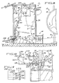
- Figure 1 is an elevational view of strap dispensing and accumulating apparatus according to a preferred embodiment of this invention.
- Figure 2, on an enlarged scale compared to Figure 1, is an exploded perspective detail showing a strap chute of such dispensing and accumulating apparatus, as associated with certain elements of a strapping head of a strapping machine.
- Figure 3, on an enlarged scale, compared to Figure 1, is a sectional view taken along
line 2--2 of Figure 1, in a direction indicated by arrows, to show a strap being fed through a strap chute of such dispensing and accumulating apparatus. - Figure 4 on a slightly larger scale compared to Figure 1, is a plan view of such dispensing and accumulating apparatus.
- Figure 5, on an enlarged scale compared to Figure 1, is a view taken partly in cross-section, along
line 5--5 of Figure 1, in a direction indicated by arrows. - Figures 6 and 7 respectively are sectional views taken along line 7--7 of Figure 5, in a direction indicated by arrows, to show a clutch in a disengaged condition in Figure 6 and in an engaged condition in Figure 7.
- Figure 8 is an enlarged detail taken from Figure 1. Figure 8 differs from Figure 1 in that an strap guide shown in a lowered condition in Figure 1 is shown in a raised condition in Figure 8.
- Figure 9 is a schematic diagram of electrical components of the apparatus shown in Figure 1 and other views.
- Figure 10, on a larger scale compared to Figure 8, is a fragmentary detail of certain elements of strap dispensing and accumulating apparatus constituting a simplified embodiment of this invention.
- As shown in Figure 1 and other views, strap dispensing and accumulating
apparatus 10 constitutes a preferred embodiment of this invention. Theapparatus 10 utilizes a strap S of thermoplastic material, such as a polyester strap or a polypropylene strap, which is preferred. SIGNODE™ CONTRAX™ strap, as available commercially from Signode Industry Packing Systems, supra, is preferred. - The strap S is supplied to the apparatus by and from a strap dispenser 12 including a
supply reel 14, which holds a supply of the strap S in an indeterminate length, over a direction-changingroller 16. The strap dispenser 12 has spaced, pivotally mountedlevers 18 enabling thesupply reel 14 to be selectively pivoted between an operative position and an inoperative position. Thesupply reel 14 is shown, in Figure 4, in the operative position in full lines and in the inoperative position in phantom lines. Thesupply reel 14 can be thus pivoted to the inoperative position when it is necessary to replace thesupply reel 14 after the supply of the strap S on thesupply reel 14 has been exhausted. Thestrap dispenser 14 may be a SIGNODE™ Model DF-12D dispenser, as available commercially from Signode Industry Packaging Systems, supra. - The strap S is supplied by and from the
apparatus 10 to a strapping machine M including a strappinghead 20, which is shown fragmentarily in Figures 1 and 2, of a known type. Except for certain elements of the strappinghead 20, the strapping machine M is not shown. The strappinghead 20 has two feedingrollers 22 and two tensioning or take-uprollers 24. When driven by the strappinghead 20 in a known manner, the feedingrollers 22 draw the strap S forwardly at a given rate into the strapping machine M from theapparatus 10. The feedingrollers 22 are arranged to be selectively disengaged from the strap S, in a known manner, so as to enable the strap S to be drawn backwardly by thetensioning rollers 24. When driven by the strappinghead 20 in a known manner, thetensioning rollers 24 draw the strap S backwardly at a similar rate from the strapping machine M into theapparatus 10. Thetensioning rollers 24 are arranged to be selectively disengaged from the strap S, in a known manner, so as to enable the strap S to be drawn forwardly by the feedingrollers 22. - Thus, the strapping
head 20 is operable, in a known manner, to feed the strap S around a package (not shown) via a strap chute (not shown) when the feedingrollers 22 are driven with thetensioning rollers 24 disengaged from the strap S. Also, the strappinghead 20 is operable, in a known manner, to tension the strap S in a tensioned loop around the package when thetensioning rollers 24 are driven with the feedingrollers 22 disengaged from the strap S. Moreover, the strappinghead 20 is operable in a known manner, to weld the strap S in the tensioned loop around the package and to sever the strap S in the tensioned loop from those portions of the strap S following the tensioned loop. The strapping machine M including the strappinghead 20 may be a SIGNODE™ SPIRIT™ Model BCU strapping machine including a SIGNODE™ SPIRIT™ strapping head, as available commercially from Signode Industry Packaging Systems, supra. - The
apparatus 10 comprises a stretch-out box 30 having anend wall 32 defining astrap inlet 34 and anend wall 36 defining astrap outlet 38. Also, the stretch-out box 30 has alower wall 40 defining a guidingsurface 42, anupper wall 44, and twoside walls out box 30, one of the side walls, namely theside wall 46, is made of a transparent material, such as glass or polycarbonate, which is preferred. The distance between theside walls surface 42 is arched, as shown, and extends between a lower edge of thestrap inlet 34 and a lower edge of thestrap outlet 38. - The
apparatus 10 comprises an elongate, substantiallyrigid strap guide 60 having two opposite ends 62, 64, which are rounded, as shown. Thestrap guide 60 is mounted pivotally between theside walls strap outlet 38, via apivot pin 66 extending through thestrap guide 60, near thestrap guide end 62, and defining an axis, about which thestrap guide 60 is pivotable. Thestrap guide 60 is pivotable between an upper, inoperative position, in which it is shown in phantom lines in Figure 1 and in full lines in Figure 8, and a lower, operative position, in which it is shown in full lines in Figure 1. Thestrap guide 60 is biased gravitationally toward the lower position. - The
end wall 36 defining thestrap outlet 38 is made of a magnetizable material, such as carbon steel, which is preferred. Apermanent magnet 70 is mounted via screws (not shown) in arecess 72 in thestrap guide 60. Thepermanent magnet 70 coacts with theend wall 36 to hold thestrap guide 60 releasably in the upper position. Theside wall 46 made of a transparent material has an aperture 74 (see Figure 1) enabling a user manually to release thestrap guide 60 from the upper position, by inserting one of his or her fingers or a small tool (not shown) and pushing thestrap guide 60 so as to separate thepermanent magnet 70 from theend wall 36. As biased gravitationally, thestrap guide 60 tends to pivot toward the lower position after it has been released from the upper position. - The
strap guide 60 has a guidingsurface 80, which is its lower surface when it is in its lower position. The guidingsurface 80 conforms to the guidingsurface 42 of thelower wall 40 and overliessuch surface 42 in the lower position of thestrap guide 60. In its lower position, thestrap guide 60 coacts with thelower wall 40, along with theside walls surface 80 of thestrap guide 60 and the guidingsurface 42 of thelower wall 40, and between theside walls out box 30, via thestrap outlet 38. The strap S is guided, in the channel defined thereby, from thestrap inlet 34 to thestrap outlet 38. - As shown primarily in Figures 5, 6, and 7, the
apparatus 10 comprises amechanism 90 for feeding the strap S from the strap dispenser 12, over the direction-changingroller 16, into the stretch-out box 30, via thestrap inlet 34. Thefeeding mechanism 90 is arranged to feed the strap S into the stretch-out box 30 at a faster rate compared to the given rate at which the strappinghead 20 draws the strap S from the stretch-out box 30. Themechanism 90 comprises abase 92, on which a fractional horsepower, alternating-current motor 94 is mounted. Themotor 94 has a shaft 96, which is driven by themotor 94, and to which ashaft 98 is coupled for conjoint rotation, via acoupler 100. A polyurethane-coatedroller 102 having a strap groove 104 is mounted on theroller shaft 98 for conjoint rotation, via a key 106 fitting into keyways in theroller 102 and in theshaft 98. The strap groove 104 accommodates the strap S engaging theroller 102. Theshaft 98 extends through alignedapertures upright plates annular bearings apertures upright plates screws 120, to abracket 122, which is mounted to thebase 92. - A
steel roller 130 is journalled on ashaft 132, via a roller bearing 134, which is mounted within theroller 130 and around theshaft 132. Theshaft 132 extends through anaperture 136 in theupright plate 112 and through an aperture 138 in theupright plate 114. Theapertures 136, 138, are shaped so as to permit theshaft 132 to translate freely in theapertures 136, 138, and so as to permit theshaft 132 to be vertically displaced between an upper position and a lower position. Theshaft 132 is shown in its lower position in Figure 7 and in an intermediate position in Figures 5 and 6. Thesteel roller 130 fits loosely into the strap groove 104 of the polyurethane-coatedroller 102 and overlies the strap S in the strap groove 104. - The
shaft 132 is biased toward its lower position by twocoiled springs shaft 132, near its opposite ends 146, 148. Thecoiled spring 142 is retained, at its upper end, in asocket 150 opening downwardly in ablock 152, which is mounted to theupright plate 112 byscrews 153. Thecoiled spring 144 is retained, at its upper end, in a socket 154 opening downwardly in ablock 158, which is mounted to theupright plate 114 by screws 160. - A pair of manually
actuatable levers shaft 132 temporarily from its lower position. Thelever 170 mounted pivotally to theupright plate 112, via a pivot pin (not shown) so as to engage theshaft 132 between thecoiled spring 142 and theupright plate 112. Thelever 172 is mounted pivotally to theupright plate 114, via apivot pin 176, so as to engage theshaft 132 between thecoiled spring 144 and theupright plate 114. Thelevers rod 178. Therod 178 is arranged to engage aflanged plate 180, which is mounted to theupright plates levers - Strap-guiding
blocks upright plates rollers mechanism 90 from the strap dispenser 12. Strap-guidingblocks upright plates rollers 102, 104 and in front of thestrap inlet 34 of the stretch-out box 30, facilitate feeding the strap S from themechanism 90 into the stretch-out box 30. - An elongate,
flexible chute 200 having aninlet end 202 and anoutlet end 204 and comprising an elongate, flexible, polymeric tube, which is flattened so as to have an oblong cross-section shown in Figure 3, is connected between the stretch-out box 30 and the strappingmachine 20. Theinlet end 202 of thechute 200 is connected viashoulder bolts 206 to abracket 208, which is mounted to the stretch-out box 30, near thestrap outlet 38. Theoutlet end 204 ofchute 200 is connected to the strappingmachine 20, via abracket 212 and alatch 214. Thechute 200 is connected so as to guide the strap S when the strap S is drawn by the feedingrollers 22 forwardly into the strappingmachine 20 from the stretch-out box 30 and when the strap S is drawn by thetensioning rollers 24 backwardly into the stretch-out box 30 from the strappingmachine 20. - The
bracket 212 is mounted to the strappingmachine 20, near the feedingrollers 22. Theinlet end 202 of thechute 200 has twotriangular recesses triangular recess 216 accommodates atriangular flange 220, which is provided on thebracket 216, and thetriangular recess 218 accommodates atriangular portion 222 of thelatch 214. Thelatch 214 is mounted pivotally to thebracket 212, via apivot pin 220 fitting into anelongate slot 222 in thebracket 212. Theelongate slot 222 enables thepivot pin 220 to be adjustably located. Thus, thelatch 214 is mounted for pivotal movement between a closed position and an opened position. Thelatch 214 is shown, in Figure 2, in its closed position in full lines and in its opened position in phantom lines. Athumb screw 226, which is carried by thelatch 214, is arranged to be manually turned in a clockwise direction (as shown) until it bears against thebracket 212, in the closed position of thelatch 214, when it is desired to latch theoutlet end 204 of thechute 200 to thebracket 212. Thethumb screw 226 is arranged to be oppositely turned when it is desired to pivot thelatch 214 to the opened position so as to release theoutlet end 204 of thechute 200 from thebracket 212. - A
photoelectric cell 230 is mounted to theend wall 32, near theupper wall 44, so as to be enclosed within the stretch-out box 30. Areflector 232 is mounted to theend wall 34, near theupper wall 44, in opposed relation to thephotoelectric cell 230. Thephotoelectric cell 230 is operable in a known manner to transmit a beam toward thereflector 232, at a predetermined level above thestrap guide 60 in the upper position, and to receive the beam, as reflected by thereflector 232, unless the beam is interrupted by the strap S in the stretch-out box 230. Because thestrap guide 60 is below the beam level when thestrap guide 60 is in the upper position, thestrap guide 60 does not interrupt the beam. As shown schematically in Figure 9, thephotoelectric cell 230 is arranged in a known manner to control a pair of contacts 234 in such manner that the contacts 234 are closed except when the beam is interrupted and in such manner that the contacts 234 are opened when the beam is interrupted. - A manually actuatable, push-to-close, pull-to-
open switch 240 is mounted to theside wall 46, near theupper wall 44, and is connected via a fuse 242 (see Figure 9) to a source of electrical power. A runninglamp 244 is connected to theswitch 240 so as to indicate when theswitch 240 is closed. As shown in Figure 9, themotor 94 is connected to theswitch 240, via a pair ofcontacts 246, which are controlled by arelay 248. Moreover, therelay 248 is connected to theswitch 240, via the contacts 234 controlled by thephotoelectric cell 230. Consequently, themotor 94 is enabled when theswitch 240 is closed, unless the contacts 234 are opened by thephotoelectric cell 230. - Accordingly, such dispensing and accumulating apparatus can be effectively used to thread the strap S from the strap dispenser 12 into the strapping
head 20 of the strapping machine M. Initially, thestrap guide 60 is pivoted to its lower position. Thereupon, thelevers shaft 132 temporarily from its lower position, the strap S is inserted, at its leading end, into the strap groove 104 of the polyurethane-coatedroller 102 and below thesteel roller 130, and thelevers steel roller 130, which is biased by thecoiled springs shaft 132. Next, theswitch 240 is pressed, so as to actuate themotor 94 of thefeeding mechanism 90. When themotor 94 is actuated, the polyurethane-coatedroller 102 is driven and coacts with thesteel roller 130 to feed the strap S through the channel defined by thestrap guide 60 and thelower wall 40, along with theside walls flexible chute 200, into the strappinghead 20. In the strappinghead 20, the feedingrollers 22 and thetensioning rollers 24 are disengaged, so as to permit the strap S to be further fed into the strappinghead 20. - When the strap S being fed into the strapping
head 20 encounters sufficient resistance, the strap S is arrested at its leading end and begins to accumulate in the stretch-out box 30. The strap S accumulating in the stretch-out box 30 pivots thestrap guide 60 from its lower position toward its upper position. When the strap S accumulating in the stretch-out box 30 reaches a predetermined level where the strap S interrupts the beam transmitted by thephotoelectric cell 230 and reflected by thereflector 232, thephotoelectric cell 230 opens the contacts 234 so as to deactuate themotor 94 of thefeeding mechanism 90 temporarily. - Subsequently, when the strapping machine M is operated, the feeding
rollers 22 of the strappinghead 20 are engaged with the strap S and are driven so as to draw accumulated portions of the strap S from the stretch-out box 30 into the strappinghead 20. Thetensioning rollers 24 are disengaged from the strap S when the strap S is drawn into the strappinghead 20. When the strap S accumulated in the stretch-out box 30 no longer reaches the predetermined level at which the strap S interrupts the beam transmitted by thephotoelectric cell 230 and reflected by thereflector 232, thephotoelectric cell 230 closes the contacts 234 so as to enable themotor 94 of thefeeding mechanism 90 to be again actuated, whereupon thefeeding mechanism 90 feeds a further quantity of the strap S into the stretch-out box 30. - Since the
feeding mechanism 90 is arranged to feed the strap S into the stretch-out box 30 at a faster rate compared to the given rate at which the strappinghead 20 draws the strap S from the stretch-out box 30, thefeeding mechanism 90 feeds the strap S into the stretch-out box 30 until the strap S accumulating in the stretch-out box 30 again reaches the predetermined level at which the strap S interrupts the beam emitted by thephotoelectric cell 230 and reflected by thereflector 232, whereupon thephotoelectric cell 230 again opens the contacts 234 so as to deactuate themotor 94 of thefeeding mechanism 90 temporarily. - Thereupon, when the strapping
head 20 tensions the strap S, thetensioning rollers 24 of the strappinghead 20 are engaged with the strap S and are driven so as to draw an excess quantity of the strap S from the strappinghead 20 into the stretch-out box 30. The feedingrollers 22 are disengaged from the strap S when the strap S is drawn from the strappinghead 20. The strap S drawn from the strappinghead 20 into the stretch-out box 30 accumulates in the stretch-out box 30, along with the strap S fed into the stretch-out box 30 by thefeeding mechanism 90, as controlled by thephotoelectric cell 230. - These operations of such dispensing and accumulating apparatus are repeated, as the strapping machine M is cycled from package to package, until the supply of the strap S on the
supply reel 14 of the strap dispenser 12 has been exhausted. Thesupply reel 14 may be then replaced with a similar reel holding a new supply of a similar strap. - In an alternate embodiment of this invention, as shown in Figure 10 the
flexible chute 200 is omitted and theapparatus 10 is provided with astrap snubber 250, which is not used in the preferred embodiment. Thestrap snubber 250 is mounted on a bracket 252, which is mounted to the stretch-out box 30, near thestrap outlet 38. The bracket 252 includesupper plate 254 defining a guidingsurface 256, which is the upper surface of theupper plate 254. - The
strap snubber 250 comprises abracket 260 having atop wall 262, and having twoside walls 264, 266. Also, thestrap snubber 250 comprises ablade 270, which is made of spring steel. Theblade 270 is shaped, as shown, so as to define a mounting portion 272, acurved portion 274, and adistal portion 276. The mounting portion 272 overlies thetop wall 262 and is mounted to thetop wall 262 viascrews 278. Thecurved portion 274 is disposed so as to press a portion of the strap S against the guidingsurface 256 of the bracket 252, so as to impart frictional resistance to the strap S passing in either direction through thestrap outlet 38. Thedistal portion 276 extends beneath thetop wall 262. An adjustingscrew 280 having anut 282 threaded thereon is threaded through a threaded aperture 284 in thetop wall 262, so as to bear against thedistal portion 276. The adjustingscrew 280 may be manually adjusted to different positions, in which the adjustingscrew 280 may be then secured by thenut 282, so that theblade 270 can impart adjustable levels of frictional resistance to the strap S passing in either direction through thestrap outlet 38. - It is convenient to refer to strap dispensing and accumulating apparatus according to the preferred embodiment described above as "self-threading" and to refer to such apparatus according to the alternate embodiment described above as "auto-feeding".
Claims (8)
- Strap dispensing and accumulating apparatus (10) for use with a strap (S) of thermoplastics material and with a strapping machine (M) having a strapping head operable to draw portions of the strap forwards into the strapping machine and to draw portions of the strap backwards from the strapping machine, the dispensing and accumulating apparatus (10) being useful to accumulate strap portions before those portions are drawn by the strapping head into the strapping machine, to accumulate strap portions drawn by the strapping head from the strapping machine, and to dispense accumulated strap portions of the strap to the strapping head, said dispensing and accumulating apparatus comprising(a) a stretch-out box (30) having a strap inlet (34) and a strap outlet (36) and including two side walls (46,48) in parallel relation to each other and a lower wall (40) defining a guiding surface between the strap inlet (34) and the strap outlet (36),(b) an strap guide (60) disposed between the side walls (46,48) and movable between a lower, operative position and an upper, inoperative position, the strap guide (60) having a guiding surface (80), which overlies the guiding surface (42) of the lower wall (40) in the lower position of the strap guide (60), and,(c) means (90) for feeding a strap from a supply of the strap into the stretch-out box (30), via the strap inlet (34),wherein the strap guide (60) in the lower position constitutes means coacting with the lower wall (40), along with the side walls (46,48), to define a channel between the strap inlet (34) and the strap outlet (36) for guiding a strap (S) being fed into the stretch-out box (30) via the strap inlet (34).
- An apparatus according to claim 1, wherein the strap guide (60) is an elongate member having two opposite ends and is mounted pivotally between the side walls (46,48), near the strap outlet (36), for pivotal movement about an axis near one of the opposite ends of the strap guide (60), in such manner that the strap guide (60) is pivotable between the lower and upper positions.
- An apparatus according to claim 1 or 2, with the feeding means (90) arranged to be selectively actuated and deactuated, said apparatus further comprising means (230) for detecting when a strap (S) accumulating in the stretch-out box (30) has reached a predetermined level, and for deactuating the feeding means (90) temporarily when the detecting device has detected that the accumulating strap (S) has reached the predetermined level.
- An apparatus according to claim 3, in which the means for detecting comprises photoelectric means (230) for detecting when a strap (S) accumulating in the stretch-out box (30) has reached a predetermined level above the strap guide in the upper position.
- An apparatus according to any one of the preceding claims, further comprising an elongate flexible, polymeric chute (200) connected to the stretch-out box (30), near the strap outlet (38), the flexible chute (200) being adapted to guide a strap (S) between the strap outlet (36) and the strapping machine (M).
- A strapping system for a strap of thermoplastics material, comprising a combination of a strapping machine (M) having a strapping head operable to draw portions of the strap forwards into the strapping machine and to draw portions of the strap backwards from the strapping machine and a strap dispensing and accumulating apparatus (30) in accordance with any one of the preceding claims.
- A combination according to claim 6 when dependent upon claim 5, wherein the flexible chute (200) has an inlet end (202) connected to the stretch-out box (30), near the strap outlet (36), and an outlet end (204) connected to the strapping head (M), wherein said combination comprises means including a bracket (220) and a latch (214) for connecting the outlet end (204) of the flexible chute (200) to the strapping head (M), the bracket (220) being mounted to the strapping head, the latch (214) being movable between an opened position and a closed position and being adapted to latch the outlet end (204) of the flexible chute to the bracket (220) when moved to the closed position, and wherein the outlet end (204) of the flexible chute (200) has at least one recess (216,218) and the bracket (220) or the latch (214) is shaped to fit into the recess (216,218) when the latch (214) is moved to the closed position.
- A combination according to claim 6 or 7, wherein the strapping head (M) is arranged to draw the strap (S) forwards at a given rate and wherein the feeding means (90) is arranged to feed the strap into the stretch-out box (30) at a faster rate.
Applications Claiming Priority (2)
| Application Number | Priority Date | Filing Date | Title |
|---|---|---|---|
| US07/610,434 US5112004A (en) | 1990-11-07 | 1990-11-07 | Strap dispensing and accumulating apparatus and combination of same with strapping machine |
| US610434 | 2003-06-30 |
Publications (1)
| Publication Number | Publication Date |
|---|---|
| EP0485097A1 true EP0485097A1 (en) | 1992-05-13 |
Family
ID=24445003
Family Applications (1)
| Application Number | Title | Priority Date | Filing Date |
|---|---|---|---|
| EP91309947A Ceased EP0485097A1 (en) | 1990-11-07 | 1991-10-28 | Strap dispensing and accumulating apparatus and combination of same with strapping machine |
Country Status (9)
| Country | Link |
|---|---|
| US (1) | US5112004A (en) |
| EP (1) | EP0485097A1 (en) |
| AU (1) | AU642544B2 (en) |
| BE (1) | BE1004827A3 (en) |
| CA (1) | CA2049801A1 (en) |
| DE (1) | DE4134496A1 (en) |
| GB (1) | GB2251590B (en) |
| NL (1) | NL9101813A (en) |
| NZ (1) | NZ239682A (en) |
Cited By (5)
| Publication number | Priority date | Publication date | Assignee | Title |
|---|---|---|---|---|
| DE19516043A1 (en) * | 1995-05-04 | 1996-11-07 | Mosca G Maschf | Package pieces tying machine by weldable plastics type |
| WO2000035755A1 (en) * | 1998-12-17 | 2000-06-22 | The Mead Corporation | Apparatus and method for applying endless bands to cartons |
| WO2008103952A1 (en) | 2007-02-23 | 2008-08-28 | Enterprises International, Inc. | Apparatus and method for applying a strap around a bundle of objects |
| WO2017061866A1 (en) * | 2015-10-08 | 2017-04-13 | Bandall Productie B.V. | Apparatus for banding products |
| EP3360805A1 (en) * | 2017-02-13 | 2018-08-15 | Schneider & Ozga GmbH & Co. KG | Strapping device |
Families Citing this family (13)
| Publication number | Priority date | Publication date | Assignee | Title |
|---|---|---|---|---|
| US5516022A (en) * | 1994-02-28 | 1996-05-14 | Illinois Tool Works, Inc. | Method and apparatus for a two speed strap take up |
| DE4427135A1 (en) * | 1994-07-30 | 1996-02-01 | Signode Bernpak Gmbh | Strapping strip feed device for pack strapping machine |
| US5890641A (en) * | 1997-09-18 | 1999-04-06 | The Whitaker Corporation | Wire movement and fault detector |
| US6101792A (en) * | 1998-11-24 | 2000-08-15 | Noonan; Jim | Feed guide for strapping machine |
| DE19920724C1 (en) * | 1999-05-05 | 2000-09-07 | Strapex Holding Ag | Deflection unit for the plastics ribbon at a wrapping machine has various positions for the ribbon entry and outlet channels according to requirements with a flexible guide at the inner deflection roller |
| US6418838B1 (en) * | 2000-06-22 | 2002-07-16 | Illinois Tool Works | Strapping machine having an easy clear strap accumulator box |
| JP3568462B2 (en) * | 2000-07-10 | 2004-09-22 | 日東電工株式会社 | Sealing device |
| DE20206434U1 (en) | 2002-04-23 | 2002-08-14 | Maschinenfabrik Gerd Mosca GmbH, 69428 Waldbrunn | Supply roll with a strapping |
| JP2004142830A (en) * | 2002-09-30 | 2004-05-20 | Strapack Corp | Strapping packing machine |
| US7111481B2 (en) * | 2004-02-17 | 2006-09-26 | The Bradbury Company | Methods and apparatus for controlling flare in roll-forming processes |
| US7798060B2 (en) * | 2007-10-24 | 2010-09-21 | Illinois Tool Works Inc. | Modular strap dispenser with feed motor |
| US8310324B2 (en) * | 2008-04-11 | 2012-11-13 | Will Harris | Releasable guide and methods for using same |
| ES2870996T3 (en) * | 2018-04-19 | 2021-10-28 | Titan Umreifungstechnik Gmbh & Co Kg | Strapping device |
Citations (2)
| Publication number | Priority date | Publication date | Assignee | Title |
|---|---|---|---|---|
| US2575899A (en) * | 1940-12-23 | 1951-11-20 | Gerrard Steel Strapping Compan | Automatic wire tying machine |
| GB2206867A (en) * | 1987-07-08 | 1989-01-18 | Strapack Corp | Band loading apparatus in a packaging machine |
Family Cites Families (17)
| Publication number | Priority date | Publication date | Assignee | Title |
|---|---|---|---|---|
| US2135105A (en) * | 1937-05-12 | 1938-11-01 | Harry A Knauff | Latch |
| US2352437A (en) * | 1941-12-16 | 1944-06-27 | United Carr Fastener Corp | Clasp fastener |
| US3074661A (en) * | 1957-11-22 | 1963-01-22 | Ampex | Magnetic tape machine |
| US2993659A (en) * | 1958-04-10 | 1961-07-25 | Western Union Telegraph Co | Tape winder |
| US3177749A (en) * | 1960-05-27 | 1965-04-13 | Westinghouse Electric Corp | Control for feeding, measuring, and cutting strip material |
| US3137426A (en) * | 1960-11-24 | 1964-06-16 | Forsch Anstalt Fuer Mechanik | Reserve container |
| JPS5144472B2 (en) * | 1974-02-18 | 1976-11-29 | ||
| SU523834A1 (en) * | 1974-04-29 | 1976-08-05 | Опытное Производственно-Техническое Объединение "Техрыбпром" | Ribboning device |
| US3966245A (en) * | 1975-01-30 | 1976-06-29 | Losenno Luigi G | Multioperational latch |
| US4364503A (en) * | 1980-05-20 | 1982-12-21 | Monarch Marking Systems, Inc. | Web feeding method and apparatus for a printer |
| US4500043A (en) * | 1983-08-01 | 1985-02-19 | Corning Glass Works | Low tension winding apparatus |
| US4669766A (en) * | 1984-02-10 | 1987-06-02 | Hanchett Entry Systems, Inc. | Door holding magnet |
| US4577837A (en) * | 1984-07-30 | 1986-03-25 | Marvin Berg | Locking mechanism for extendible telescoping tubular members |
| US4557427A (en) * | 1984-10-15 | 1985-12-10 | Interlake, Inc. | Powered strap accumulator |
| US4651944A (en) * | 1985-05-06 | 1987-03-24 | Signode Corporation | Strap accumulator |
| JPS6442205U (en) * | 1987-04-25 | 1989-03-14 | ||
| US4978244A (en) * | 1988-03-02 | 1990-12-18 | Interlock Structures International, Inc. | Fastener apparatus |
-
1990
- 1990-11-07 US US07/610,434 patent/US5112004A/en not_active Expired - Lifetime
-
1991
- 1991-08-23 CA CA002049801A patent/CA2049801A1/en not_active Abandoned
- 1991-09-05 NZ NZ239682A patent/NZ239682A/en unknown
- 1991-10-18 DE DE4134496A patent/DE4134496A1/en not_active Withdrawn
- 1991-10-28 EP EP91309947A patent/EP0485097A1/en not_active Ceased
- 1991-10-28 GB GB9122847A patent/GB2251590B/en not_active Expired - Fee Related
- 1991-10-29 NL NL9101813A patent/NL9101813A/en not_active Application Discontinuation
- 1991-11-04 AU AU86952/91A patent/AU642544B2/en not_active Ceased
- 1991-11-07 BE BE9101027A patent/BE1004827A3/en not_active IP Right Cessation
Patent Citations (2)
| Publication number | Priority date | Publication date | Assignee | Title |
|---|---|---|---|---|
| US2575899A (en) * | 1940-12-23 | 1951-11-20 | Gerrard Steel Strapping Compan | Automatic wire tying machine |
| GB2206867A (en) * | 1987-07-08 | 1989-01-18 | Strapack Corp | Band loading apparatus in a packaging machine |
Cited By (11)
| Publication number | Priority date | Publication date | Assignee | Title |
|---|---|---|---|---|
| DE19516043A1 (en) * | 1995-05-04 | 1996-11-07 | Mosca G Maschf | Package pieces tying machine by weldable plastics type |
| WO2000035755A1 (en) * | 1998-12-17 | 2000-06-22 | The Mead Corporation | Apparatus and method for applying endless bands to cartons |
| WO2008103952A1 (en) | 2007-02-23 | 2008-08-28 | Enterprises International, Inc. | Apparatus and method for applying a strap around a bundle of objects |
| US7770369B2 (en) | 2007-02-23 | 2010-08-10 | Enterprises International, Inc. | Apparatuses and methods for applying a strap around a bundle of objects |
| RU2454359C2 (en) * | 2007-02-23 | 2012-06-27 | Энтерпрайзиз Интернэшнл, Инк. | Device and method for applying tape around bundle of articles |
| US8584438B2 (en) | 2007-02-23 | 2013-11-19 | Enterprises International, Inc. | Apparatuses and methods for applying a strap around a bundle of objects |
| US9745091B2 (en) | 2007-02-23 | 2017-08-29 | Enterprises International, Inc. | Method for accumulating a strap within an accumulator of a strapping apparatus |
| WO2017061866A1 (en) * | 2015-10-08 | 2017-04-13 | Bandall Productie B.V. | Apparatus for banding products |
| NL2015588B1 (en) * | 2015-10-08 | 2017-05-02 | Bandall Productie B V | Device for banding products. |
| US10745157B2 (en) | 2015-10-08 | 2020-08-18 | Bandall Productie B.V. | Apparatus for banding products |
| EP3360805A1 (en) * | 2017-02-13 | 2018-08-15 | Schneider & Ozga GmbH & Co. KG | Strapping device |
Also Published As
| Publication number | Publication date |
|---|---|
| GB2251590B (en) | 1994-02-16 |
| AU642544B2 (en) | 1993-10-21 |
| US5112004A (en) | 1992-05-12 |
| NL9101813A (en) | 1992-06-01 |
| AU8695291A (en) | 1992-05-14 |
| GB2251590A (en) | 1992-07-15 |
| DE4134496A1 (en) | 1992-05-14 |
| CA2049801A1 (en) | 1992-05-08 |
| GB9122847D0 (en) | 1991-12-11 |
| NZ239682A (en) | 1993-04-28 |
| BE1004827A3 (en) | 1993-02-02 |
Similar Documents
| Publication | Publication Date | Title |
|---|---|---|
| US5112004A (en) | Strap dispensing and accumulating apparatus and combination of same with strapping machine | |
| JP2543483B2 (en) | Strap cutting and releasing mechanism of the binding machine | |
| EP2265501B1 (en) | Strap exchanger for a strapping system | |
| CA2679051C (en) | Apparatus and method for applying a strap around a bundle of objects | |
| EP0938429A1 (en) | Strapping machine having primary and secondary tensioning units and a control system therefor | |
| US4638696A (en) | Apparatus for dispensing strip material or the like | |
| US5788139A (en) | Stitching machine head and wire cassette therefor | |
| JPS6036314B2 (en) | A device for drawing out and cutting sewing thread in a sewing machine | |
| US20060175458A1 (en) | Strap dispenser with start assist | |
| GB2142282A (en) | Automatic packing machine | |
| US5310128A (en) | Tape storage apparatus for mailing machine | |
| US4448330A (en) | Dispenser devices for flowable contents in compressible tubes | |
| US5596916A (en) | Method for preventing jams in a tape ejecting apparatus | |
| US3041961A (en) | Strap feeding and guiding device | |
| US3261251A (en) | Taping gun | |
| US4331302A (en) | Web feeding method and apparatus for a printer | |
| KR200150137Y1 (en) | Strap-Supply Mechanism for Automatic Strapping Machines | |
| US4508252A (en) | Web feeding method and apparatus for a printer | |
| US2850993A (en) | Packaging apparatus | |
| CA1053617A (en) | Rolled sheet predetermined length dispenser with dispensed strip priving means | |
| US5539287A (en) | Roll-tape knife control for a tape-cutting apparatus in a mailing machine | |
| JP3060028B2 (en) | Automatic envelope sealing device | |
| US2021314A (en) | Tape serving machine | |
| US5452214A (en) | Method for initializing a tape feeding, cutting and ejection apparatus for a mailing machine | |
| HK1152281B (en) | Strap exchanger for a strapping system |
Legal Events
| Date | Code | Title | Description |
|---|---|---|---|
| PUAI | Public reference made under article 153(3) epc to a published international application that has entered the european phase |
Free format text: ORIGINAL CODE: 0009012 |
|
| AK | Designated contracting states |
Kind code of ref document: A1 Designated state(s): AT CH DK ES FR GR IT LI LU SE |
|
| 17P | Request for examination filed |
Effective date: 19920924 |
|
| 17Q | First examination report despatched |
Effective date: 19940304 |
|
| STAA | Information on the status of an ep patent application or granted ep patent |
Free format text: STATUS: THE APPLICATION HAS BEEN REFUSED |
|
| 18R | Application refused |
Effective date: 19950113 |