EP0485085A2 - Oxide modified air electrode surface for high temperature electrochemical cells - Google Patents
Oxide modified air electrode surface for high temperature electrochemical cells Download PDFInfo
- Publication number
- EP0485085A2 EP0485085A2 EP91309643A EP91309643A EP0485085A2 EP 0485085 A2 EP0485085 A2 EP 0485085A2 EP 91309643 A EP91309643 A EP 91309643A EP 91309643 A EP91309643 A EP 91309643A EP 0485085 A2 EP0485085 A2 EP 0485085A2
- Authority
- EP
- European Patent Office
- Prior art keywords
- electrolyte
- air electrode
- particles
- cell
- oxide
- Prior art date
- Legal status (The legal status is an assumption and is not a legal conclusion. Google has not performed a legal analysis and makes no representation as to the accuracy of the status listed.)
- Granted
Links
- 0 C*C(*C)*CN Chemical compound C*C(*C)*CN 0.000 description 1
Images


Classifications
-
- H—ELECTRICITY
- H01—ELECTRIC ELEMENTS
- H01M—PROCESSES OR MEANS, e.g. BATTERIES, FOR THE DIRECT CONVERSION OF CHEMICAL ENERGY INTO ELECTRICAL ENERGY
- H01M8/00—Fuel cells; Manufacture thereof
- H01M8/10—Fuel cells with solid electrolytes
- H01M8/12—Fuel cells with solid electrolytes operating at high temperature, e.g. with stabilised ZrO2 electrolyte
-
- G—PHYSICS
- G01—MEASURING; TESTING
- G01N—INVESTIGATING OR ANALYSING MATERIALS BY DETERMINING THEIR CHEMICAL OR PHYSICAL PROPERTIES
- G01N27/00—Investigating or analysing materials by the use of electric, electrochemical, or magnetic means
- G01N27/26—Investigating or analysing materials by the use of electric, electrochemical, or magnetic means by investigating electrochemical variables; by using electrolysis or electrophoresis
- G01N27/403—Cells and electrode assemblies
- G01N27/406—Cells and probes with solid electrolytes
- G01N27/407—Cells and probes with solid electrolytes for investigating or analysing gases
- G01N27/4075—Composition or fabrication of the electrodes and coatings thereon, e.g. catalysts
-
- H—ELECTRICITY
- H01—ELECTRIC ELEMENTS
- H01M—PROCESSES OR MEANS, e.g. BATTERIES, FOR THE DIRECT CONVERSION OF CHEMICAL ENERGY INTO ELECTRICAL ENERGY
- H01M4/00—Electrodes
- H01M4/86—Inert electrodes with catalytic activity, e.g. for fuel cells
- H01M4/90—Selection of catalytic material
- H01M4/9016—Oxides, hydroxides or oxygenated metallic salts
- H01M4/9025—Oxides specially used in fuel cell operating at high temperature, e.g. SOFC
- H01M4/9033—Complex oxides, optionally doped, of the type M1MeO3, M1 being an alkaline earth metal or a rare earth, Me being a metal, e.g. perovskites
-
- Y—GENERAL TAGGING OF NEW TECHNOLOGICAL DEVELOPMENTS; GENERAL TAGGING OF CROSS-SECTIONAL TECHNOLOGIES SPANNING OVER SEVERAL SECTIONS OF THE IPC; TECHNICAL SUBJECTS COVERED BY FORMER USPC CROSS-REFERENCE ART COLLECTIONS [XRACs] AND DIGESTS
- Y02—TECHNOLOGIES OR APPLICATIONS FOR MITIGATION OR ADAPTATION AGAINST CLIMATE CHANGE
- Y02E—REDUCTION OF GREENHOUSE GAS [GHG] EMISSIONS, RELATED TO ENERGY GENERATION, TRANSMISSION OR DISTRIBUTION
- Y02E60/00—Enabling technologies; Technologies with a potential or indirect contribution to GHG emissions mitigation
- Y02E60/30—Hydrogen technology
- Y02E60/50—Fuel cells
Definitions
- This invention relates to an air electrode having discrete, small, high surface area oxide particles on its exterior surface which serve as nucleating sites for subsequently applied solid electrolyte.
- High temperature solid oxide fuel cell configurations are well known, and taught, for example, in U.S. Patent Specification no. 4,490,444 (Isenberg).
- a porous, calcia stabilized zirconia support tube having a porous air electrode of, for example calcium, strontium, magnesium or zirconium oxide doped lanthanum manganite was taught, with an attached, axially elongated, narrow interconnection strip of calcium, strontium, or magnesium oxide doped lanthanum chromite.
- the air electrode was coated with a 20 micrometer to 50 micrometer thick, solid, non-porous, yttria stabilized zirconia electrolyte.
- an electrode-protective, porous, continuous interlayer of calcium and cobalt doped yttrium chromite was disposed between the air electrode and the electrolyte.
- Partially encapsulated air electrode surfaces formed near the electrolyte-air electrode interface may also inhibit oxygen reduction reaction due to limiting the surface area for electron exchange at the interface, and allow oxygen loss from the air electrode lattice during cell operation at moderate-to-high current densities.
- One of the main objects of this invention is to reduce oxygen loss from air electrode particles in contact with the electrolyte and increase the active area for the electron exchange reactions with oxygen at the electrode-electrolyte interface.
- the present invention resides in an electrochemical cell comprising a porous, exterior cermet electrode and a porous lanthanum manganite air electrode, with stabilized zirconia solid oxide electrolyte therebetween, characterized in that the lanthanum manganite electrode surface next to the electrolyte contains a porous, discontinuous layer of a material selected from the group consisting of cerium oxide, praseodymium oxide and mixtures thereof, and where electrolyte contacts both the lanthanum manganite and the discontinuous oxide layer.
- the discontinuous layer of cerium oxide is in discrete particle form having diameters from approximately 0.01 micrometer to 0.1 micrometer, and has a high surface area of from approximately 35 m2/gram to 150 m2/gram, where from 90% to 100% of the particles are in the top 50 micrometers of the air electrode structure near the electrolyte.
- the preferred electrochemical cell is a tubular fuel cell.
- the discontinuous layer of, for example, cerium oxide prevents any encapsulation of or substantial penetration into the porous air electrode structure by the electrolyte, yet provides abundant nucleation sites for electrolyte formation and superior bonding to the air electrode surface.
- Cells made with this nucleating oxide layer have showed superior performance including lower voltage losses due to electrode polarization, and stability of the air electrode-electrolyte interface with minimal densification of the air electrode at the interface over long-term cell operation at 1,000°C.
- air or oxygen O flowing through the open interior 10 of electrochemical cell 12, for example, an operating high temperature fuel cell, permeates through optional porous support tube 13 comprising, for example, sintered calcia stabilized zirconia, to air electrode 14, where the oxygen is converted to oxygen ions at the surface of electrolyte 15.
- the oxygen ions are conducted through oxygen ion conducting electrolyte 15 to fuel electrode 16 where they react with fuel F, to generate electricity.
- longitudinal space 17 containing an axially elongated interconnection 18 which extends down a narrow axial segment of the tube, for making electrical connections from the underlying air electrode to the fuel electrode of a cell tube (not shown) lying next to it, and an electronically insulating gap 20.
- a metal or fuel electrode type of material 19 can be coated over interconnection 18. A plurality of these cells can be electrically connected together to provide a generator.
- the air electrode 14 is typically a tube of porous, calcia or strontia doped lanthanum manganite, to which zirconia is sometimes added, hereinafter defined as "lanthanum manganite", usually formed by extrusion or a slurry dip-sinter operation. This layer is usually from 500 micrometers to 2,000 micrometers thick.
- Electrolyte 15 must be a solid material through which oxygen ions can diffuse or permeate.
- the electrolyte material is preferably an oxide having a fluorite structure or a mixed oxide in the perovskite family, but other simple oxides, mixed oxides, or mixtures of simple and mixed oxides can be used.
- the preferred electrolyte material is a stabilized zirconia based ceramic, a readily available commercial material.
- a useful composition for example, is (ZrO2) 0.90( Y2O3) 0.10 as that material works well in solid oxide fuel cells.
- the electrolyte 15 is applied over a substantial portion of the inner, air electrode 14, as shown in Figure 1, next to the narrow radial segment interconnection 18, which is usually applied first so that the electrolyte can overlap it, as shown.
- An outer, porous, cermet fuel electrode 16 is then deposited over a substantial portion of the electrolyte 15, as shown in Figure 1.
- particles of an electronic conductor are applied to the electrolyte surface, then a skeleton of yttrium and zirconium oxide is usually grown around the particles by a modified electrochemical vapor deposition process.
- the preferred particles are nickel, cobalt, and alloys and mixtures thereof, as these metals are stable, sulfur resistant, and have an acceptable oxidation potential.
- the electrolyte is applied to the top of the air electrode by a chemical/electrochemical vapor deposition process using two reactant gases.
- the first reactant used to form the electrolyte 15 is a source of oxygen such as water vapor, carbon dioxide, or oxygen itself, which is fed from the inside of the tube, through the optional support 13 and the inner, porous air electrode 14.
- the second reactants used to form the electrolyte are metal halides, which are fed to the outside of the air electrode 14. Chlorides are preferred as they are inexpensive and have acceptable vapor pressures.
- the reaction of the first and second reactants produces a metal oxide electrolyte material. Where the electrolyte 14 is stabilized zirconia, it will be necessary to use a mixture of a zirconium halide and a halide of the stabilizing element as the second reactant.
- an idealized cross-section portion of the air electrode structure 14 is shown, with solid oxide electrolyte 15 just beginning to nucleate and grow over the air electrode top surface.
- Lanthanum manganite usually in the form of sintered particles 24, about 12 micrometer to 15 micrometers in diameter, form an air electrode surface containing interconnecting pores or voids, such as 26 and 28.
- the term "particle diameter” as used herein will mean the length measurement of the particles, since the particles are rarely perfectly round.
- the electrolyte layer 15 will be much thicker than shown, and will be non-porous.
- the air electrode surface next to the electrolyte contains a porous, thin, discontinuous layer of at least one of cerium oxide or praseodymium oxide, preferably as discrete, high surface area particles 30, which provide nucleating sites for subsequent electrolyte deposition.
- Exterior cermet fuel electrode (not shown) is applied after electrolyte formation.
- These particles 30 have diameters of from approximately 0.01 micrometer to 0.1 micrometer, and so, are substantially smaller than the sintered lanthanum manganite particles 24. These particles are chemically stable in oxygen at 1,000°C, do not react with the air electrode material at 1,000°C, and are oxygen ion as well as electron conducting. These particles have high surface areas of from approximately 35 m2/gram to 150 m2/gram, most preferably from 50 m2/gram to 100 m2/gram, providing a vast number of sites for nucleation and growth of electrolyte by contact of halide vapors with oxygen containing vapors by chemical vapor deposition, as described previously.
- these particles 30 are both electronic and ion-conducting, they also contribute to further electrolyte deposition by electrochemical vapor deposition as the non-porous electrolyte film continues to grow thicker with time.
- the particles 30 are cerium oxide particles. Particles above or below the stated particle size range and surface area range will not provide as advantageous a number of nucleating sites and can allow particle plugging of the air electrode pores or excessive electrolyte impregnation into the air electrode.
- cerium oxide or praseodymium oxide particles such as particles 31, may be deposited within interior pores 26 or 28 of the air electrode structure, but preferably, from 90% to 100% of the particles will be in the top 50 micrometers of the air electrode structure, most preferably in the top 20 micrometers of the air electrode structure, near the electrolyte 15.
- the discontinuous layer of particles 30 can be applied by any means, preferably by simple dusting with oxide powder, or a slurry dip-sinter operation. A variety of modified impregnation techniques may also be used so long as the oxide is formed primarily at the interface between the air electrode structure 14 and the electrolyte 15.
Landscapes
- Chemical & Material Sciences (AREA)
- Engineering & Computer Science (AREA)
- Life Sciences & Earth Sciences (AREA)
- Chemical Kinetics & Catalysis (AREA)
- Electrochemistry (AREA)
- Health & Medical Sciences (AREA)
- Materials Engineering (AREA)
- General Chemical & Material Sciences (AREA)
- Physics & Mathematics (AREA)
- General Health & Medical Sciences (AREA)
- General Physics & Mathematics (AREA)
- Immunology (AREA)
- Pathology (AREA)
- Analytical Chemistry (AREA)
- Molecular Biology (AREA)
- Biochemistry (AREA)
- Sustainable Energy (AREA)
- Sustainable Development (AREA)
- Manufacturing & Machinery (AREA)
- Inert Electrodes (AREA)
- Fuel Cell (AREA)
- Hybrid Cells (AREA)
Abstract
Description
- This invention relates to an air electrode having discrete, small, high surface area oxide particles on its exterior surface which serve as nucleating sites for subsequently applied solid electrolyte.
- High temperature solid oxide fuel cell configurations are well known, and taught, for example, in U.S. Patent Specification no. 4,490,444 (Isenberg). There, a porous, calcia stabilized zirconia support tube, having a porous air electrode of, for example calcium, strontium, magnesium or zirconium oxide doped lanthanum manganite was taught, with an attached, axially elongated, narrow interconnection strip of calcium, strontium, or magnesium oxide doped lanthanum chromite. The air electrode was coated with a 20 micrometer to 50 micrometer thick, solid, non-porous, yttria stabilized zirconia electrolyte. A porous, nickel-zirconia cermet, exterior fuel electrode, about 50 micrometers thick, covered most of the electrolyte. In another embodiment, taught in U.S. Patent Specification no. 4,547,437 (Isenberg et al.), an electrode-protective, porous, continuous interlayer of calcium and cobalt doped yttrium chromite was disposed between the air electrode and the electrolyte.
- In conventionally fabricated tubular fuel cells, electrolyte penetration within the air electrode and encapsulation of the air electrode surface by the electrolyte film has been observed near the air electrode-electrolyte interface. After electrical testing, the air electrode of these cells have been found to show structural changes in terms of porosity-formation and densification. Such undesirable structural changes taking place in the air electrode near the air electrode-electrolyte interface are postulated to be due to changes in the oxygen stoichiometry of the air electrode, resulting from the partial encapsulation of the air electrode particles at the air electrode-electrolyte interface. Partially encapsulated air electrode surfaces formed near the electrolyte-air electrode interface may also inhibit oxygen reduction reaction due to limiting the surface area for electron exchange at the interface, and allow oxygen loss from the air electrode lattice during cell operation at moderate-to-high current densities.
- One of the main objects of this invention is to reduce oxygen loss from air electrode particles in contact with the electrolyte and increase the active area for the electron exchange reactions with oxygen at the electrode-electrolyte interface.
- Accordingly, the present invention resides in an electrochemical cell comprising a porous, exterior cermet electrode and a porous lanthanum manganite air electrode, with stabilized zirconia solid oxide electrolyte therebetween, characterized in that the lanthanum manganite electrode surface next to the electrolyte contains a porous, discontinuous layer of a material selected from the group consisting of cerium oxide, praseodymium oxide and mixtures thereof, and where electrolyte contacts both the lanthanum manganite and the discontinuous oxide layer.
- Preferably, the discontinuous layer of cerium oxide is in discrete particle form having diameters from approximately 0.01 micrometer to 0.1 micrometer, and has a high surface area of from approximately 35 m²/gram to 150 m²/gram, where from 90% to 100% of the particles are in the top 50 micrometers of the air electrode structure near the electrolyte. The preferred electrochemical cell is a tubular fuel cell.
- The discontinuous layer of, for example, cerium oxide, prevents any encapsulation of or substantial penetration into the porous air electrode structure by the electrolyte, yet provides abundant nucleation sites for electrolyte formation and superior bonding to the air electrode surface. Cells made with this nucleating oxide layer have showed superior performance including lower voltage losses due to electrode polarization, and stability of the air electrode-electrolyte interface with minimal densification of the air electrode at the interface over long-term cell operation at 1,000°C.
- In order that the invention can be more clearly understood, convenient embodiments thereof will now be described, by way of example, with reference to the accompanying drawings in which:
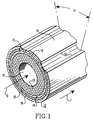
- Figure 1 is an isometric view in section of a preferred, tubular, solid oxide fuel cell which can be made according to this invention;
- Figure 2, which best shows the invention, is an idealized cross-section of the air electrode-electrolyte interface of the fuel cell of Figure 1, showing the porous, discontinuous electrolyte nucleating layer of this invention, at the beginning of electrolyte deposition; and
- Figure 3 is a graph of power output versus current density of a standard fuel cell and a fuel cell having the discontinuous, electrolyte nucleating layer of this invention.
- Referring now to Figure 1 of the drawings, air or oxygen O, flowing through the
open interior 10 of electrochemical cell 12, for example, an operating high temperature fuel cell, permeates through optional porous support tube 13 comprising, for example, sintered calcia stabilized zirconia, toair electrode 14, where the oxygen is converted to oxygen ions at the surface ofelectrolyte 15. The oxygen ions are conducted through oxygenion conducting electrolyte 15 tofuel electrode 16 where they react with fuel F, to generate electricity. Also shown in the drawing are:longitudinal space 17, containing an axially elongated interconnection 18 which extends down a narrow axial segment of the tube, for making electrical connections from the underlying air electrode to the fuel electrode of a cell tube (not shown) lying next to it, and an electronicallyinsulating gap 20. A metal or fuel electrode type ofmaterial 19 can be coated over interconnection 18. A plurality of these cells can be electrically connected together to provide a generator. - The
air electrode 14, is typically a tube of porous, calcia or strontia doped lanthanum manganite, to which zirconia is sometimes added, hereinafter defined as "lanthanum manganite", usually formed by extrusion or a slurry dip-sinter operation. This layer is usually from 500 micrometers to 2,000 micrometers thick.Electrolyte 15 must be a solid material through which oxygen ions can diffuse or permeate. The electrolyte material is preferably an oxide having a fluorite structure or a mixed oxide in the perovskite family, but other simple oxides, mixed oxides, or mixtures of simple and mixed oxides can be used. The preferred electrolyte material is a stabilized zirconia based ceramic, a readily available commercial material. A useful composition, for example, is (ZrO₂)0.90(Y₂O₃)0.10 as that material works well in solid oxide fuel cells. Theelectrolyte 15 is applied over a substantial portion of the inner,air electrode 14, as shown in Figure 1, next to the narrow radial segment interconnection 18, which is usually applied first so that the electrolyte can overlap it, as shown. - An outer, porous,
cermet fuel electrode 16 is then deposited over a substantial portion of theelectrolyte 15, as shown in Figure 1. First, particles of an electronic conductor are applied to the electrolyte surface, then a skeleton of yttrium and zirconium oxide is usually grown around the particles by a modified electrochemical vapor deposition process. The preferred particles are nickel, cobalt, and alloys and mixtures thereof, as these metals are stable, sulfur resistant, and have an acceptable oxidation potential. - The electrolyte is applied to the top of the air electrode by a chemical/electrochemical vapor deposition process using two reactant gases. The first reactant used to form the
electrolyte 15 is a source of oxygen such as water vapor, carbon dioxide, or oxygen itself, which is fed from the inside of the tube, through the optional support 13 and the inner,porous air electrode 14. The second reactants used to form the electrolyte are metal halides, which are fed to the outside of theair electrode 14. Chlorides are preferred as they are inexpensive and have acceptable vapor pressures. The reaction of the first and second reactants produces a metal oxide electrolyte material. Where theelectrolyte 14 is stabilized zirconia, it will be necessary to use a mixture of a zirconium halide and a halide of the stabilizing element as the second reactant. - Referring now to Figure 2, an idealized cross-section portion of the
air electrode structure 14 is shown, withsolid oxide electrolyte 15 just beginning to nucleate and grow over the air electrode top surface. Lanthanum manganite, usually in the form of sinteredparticles 24, about 12 micrometer to 15 micrometers in diameter, form an air electrode surface containing interconnecting pores or voids, such as 26 and 28. The term "particle diameter" as used herein will mean the length measurement of the particles, since the particles are rarely perfectly round. After complete deposition, theelectrolyte layer 15 will be much thicker than shown, and will be non-porous. The air electrode surface next to the electrolyte contains a porous, thin, discontinuous layer of at least one of cerium oxide or praseodymium oxide, preferably as discrete, highsurface area particles 30, which provide nucleating sites for subsequent electrolyte deposition. Exterior cermet fuel electrode (not shown) is applied after electrolyte formation. - These
particles 30 have diameters of from approximately 0.01 micrometer to 0.1 micrometer, and so, are substantially smaller than the sinteredlanthanum manganite particles 24. These particles are chemically stable in oxygen at 1,000°C, do not react with the air electrode material at 1,000°C, and are oxygen ion as well as electron conducting. These particles have high surface areas of from approximately 35 m²/gram to 150 m²/gram, most preferably from 50 m²/gram to 100 m²/gram, providing a vast number of sites for nucleation and growth of electrolyte by contact of halide vapors with oxygen containing vapors by chemical vapor deposition, as described previously. Since theseparticles 30 are both electronic and ion-conducting, they also contribute to further electrolyte deposition by electrochemical vapor deposition as the non-porous electrolyte film continues to grow thicker with time. Preferably, theparticles 30 are cerium oxide particles. Particles above or below the stated particle size range and surface area range will not provide as advantageous a number of nucleating sites and can allow particle plugging of the air electrode pores or excessive electrolyte impregnation into the air electrode. - As can be seen from Figure 2, some cerium oxide or praseodymium oxide particles, such as particles 31, may be deposited within
interior pores 26 or 28 of the air electrode structure, but preferably, from 90% to 100% of the particles will be in the top 50 micrometers of the air electrode structure, most preferably in the top 20 micrometers of the air electrode structure, near theelectrolyte 15. The closer to the top of the air electrode thenucleating particles 30 are placed, the better chance the air electrode pores will remain interconnecting and free to easily pass oxygen containing gas from the interior of the air electrode to theelectrolyte 15. - As can also be seen from Figure 2, the
electrolyte 15, while contacting both thelanthanum manganite particle 24 and the discontinuous layer of nucleatingparticles 30, does not encapsulate or substantially penetrate or enclose the air electrode structure. Thus,pores 26 and 28, for example, remain open. If electrolyte permeated too deeply intopores 26 and 28,air electrode particle 25, for example, would be surrounded and rendered useless as an interface site where oxygen containing gas contacts oxygen ion conducting electrolyte. Theelectrolyte 15, while not penetrating deeply into theair electrode structure 14, still is firmly bonded to the air electrode. - The discontinuous layer of
particles 30 can be applied by any means, preferably by simple dusting with oxide powder, or a slurry dip-sinter operation. A variety of modified impregnation techniques may also be used so long as the oxide is formed primarily at the interface between theair electrode structure 14 and theelectrolyte 15. - The invention will now be illustrated by the following non-limiting Example.
- Self-supported, tubular fuel cells using La.8Ca.2MnO₃ air electrode material, yttria stabilized zirconia electrolyte, nickel-zirconia cermet fuel electrode and magnesia doped lanthanum chromite interconnect were made, using well-known fabricating techniques. On one cell, cell A, a porous, discontinuous layer of CeO₂ particles, prepared by hydroxide precipitation, having diameters of approximately 0.05 micrometer to 0.1 micrometer, and surface areas of approximately 65 m²/gram, were deposited on the air electrode surface, to act as an electrolyte nucleating layer. The CeO₂ particles were deposited by rubbing them onto the air electrode surface, and all the particles remained substantially on top of the air electrode surface. The electrolyte and fuel electrode were subsequently applied to the cells by standard chemical-electrochemical vapor deposition techniques described previously.
- Fabricated cells, one with the electrolyte nucleating layer, cell A, and the other without that layer, cell B, were then electrically tested at 1,000°C in an 89% H₂-11% H₂O fuel gas mixture with air as oxidant. Electrical characteristics were obtained and are shown in Figure 3, as plots of power output in mW/cm² vs current density in mA/cm². From the data it is clear that cell A, represented by curve A, containing CeO₂ nucleating particles, produced higher power, and also showed higher performance at higher current densities than cell B, represented by curve B, not containing CeO₂ particles. Cross-sectional micrographs of cell A, showed dense electrolyte tightly connected to the air electrode.
Claims (7)
- An electrochemical cell comprising a porous exterior cermet electrode and a porous lanthanum manganite air electrode, with stabilized zirconia solid oxide electrolyte therebetween, characterized in that the lanthanum manganite electrode surface next to the electrolyte contains a porous, discontinuous layer of a material selected from the group consisting of cerium oxide, praseodymium oxide and mixtures thereof, and where the electrolyte contacts both the lanthanum manganite and the discontinuous oxide layer.
- The cell of claim 1, characterized in that the cermet electrode is nickel-zirconia, the electrolyte is a zirconia based ceramic, and the lanthanum manganite is in the form of sintered particles having particle diameters from 1 micrometer to 15 micrometers.
- The cell of claim 1, characterized in that it is in a tubular fuel cell configuration.
- The cell of claim 1, characterized in that the air electrode is from 500 micrometers to 2,000 micrometers thick, the discontinuous layer of material is in the form of discrete particles having diameters from 0.01 micrometer to 0.1 micrometer, and where 90% to 100% of the particles are in the top 50 micrometers of the air electrode structure next to the electrolyte.
- The cell of claim 1, characterized in that the discontinuous layer of material is in the form of discrete particles having a surface area of from approximately 35 m²/gram to 150 m²/gram.
- The cell of claim 1, characterized in that the discontinuous layer of material consists of cerium oxide particles, said particles being effective to provide nucleating sites for electrolyte formation.
- A plurality of the cells of claim 1, characterized in that they are electrically connected together.
Applications Claiming Priority (2)
| Application Number | Priority Date | Filing Date | Title |
|---|---|---|---|
| US07/599,530 US5106706A (en) | 1990-10-18 | 1990-10-18 | Oxide modified air electrode surface for high temperature electrochemical cells |
| US599530 | 1990-10-18 |
Publications (3)
| Publication Number | Publication Date |
|---|---|
| EP0485085A2 true EP0485085A2 (en) | 1992-05-13 |
| EP0485085A3 EP0485085A3 (en) | 1993-08-11 |
| EP0485085B1 EP0485085B1 (en) | 1996-07-31 |
Family
ID=24399997
Family Applications (1)
| Application Number | Title | Priority Date | Filing Date |
|---|---|---|---|
| EP91309643A Expired - Lifetime EP0485085B1 (en) | 1990-10-18 | 1991-10-18 | Oxide modified air electrode surface for high temperature electrochemical cells |
Country Status (9)
| Country | Link |
|---|---|
| US (1) | US5106706A (en) |
| EP (1) | EP0485085B1 (en) |
| JP (1) | JP3291304B2 (en) |
| KR (1) | KR100246723B1 (en) |
| AU (1) | AU645324B2 (en) |
| CA (1) | CA2045769C (en) |
| DE (1) | DE69121166T2 (en) |
| ES (1) | ES2090256T3 (en) |
| NO (1) | NO913821L (en) |
Cited By (5)
| Publication number | Priority date | Publication date | Assignee | Title |
|---|---|---|---|---|
| GB2258310B (en) * | 1991-07-30 | 1995-05-24 | British Gas Plc | Oxygen sensor |
| WO1996014668A3 (en) * | 1994-11-07 | 1996-08-08 | Westinghouse Electric Corp | Protective interlayer for high temperature solid electrolyte electrochemical cells |
| WO2002004934A1 (en) * | 2000-07-12 | 2002-01-17 | Robert Bosch Gmbh | Cermet electrodes containing platinum for the electrochemical reduction of oxygen |
| WO2004003537A3 (en) * | 2002-06-28 | 2004-04-29 | Rosemount Analytical Inc | Device for sensing the concentration of a combustible specie |
| EP1496555A3 (en) * | 1998-08-17 | 2010-03-24 | Ovonic Battery Company, Inc. | Composite positive electrode material and method for making same |
Families Citing this family (43)
| Publication number | Priority date | Publication date | Assignee | Title |
|---|---|---|---|---|
| NL9002168A (en) * | 1990-10-05 | 1992-05-06 | Blandikus Catharikus Jaspers E | HOLLOW ELECTRODE FOR AN ELECTROCHEMICAL CELL PROVIDED WITH AT LEAST A GAS SUPPLY AND EXHAUST OPENING, AND ELECTROCHEMICAL CELL INCLUDING SUCH ELECTRODE. |
| DK167163B1 (en) * | 1991-02-13 | 1993-09-06 | Risoe Forskningscenter | FAST OXIDE FUEL CELLS FOR OXIDATION OF CH4 |
| JPH05190180A (en) * | 1992-01-13 | 1993-07-30 | Ngk Insulators Ltd | Air electrode body of solid electrolyte type fuel cell, manufacture of air electrode body and solid electrolyte type fuel cell |
| JP2527876B2 (en) * | 1992-01-17 | 1996-08-28 | 日本碍子株式会社 | Method for manufacturing solid oxide fuel cell |
| TW269058B (en) * | 1992-04-29 | 1996-01-21 | Westinghouse Electric Corp | |
| US5432024A (en) * | 1992-10-14 | 1995-07-11 | Ngk Insulators, Ltd. | Porous lanthanum manganite sintered bodies and solid oxide fuel cells |
| EP0689724B1 (en) * | 1993-03-20 | 2000-01-12 | Keele University | Solid oxide fuel cell structures |
| US5993986A (en) * | 1995-11-16 | 1999-11-30 | The Dow Chemical Company | Solide oxide fuel cell stack with composite electrodes and method for making |
| US5670270A (en) * | 1995-11-16 | 1997-09-23 | The Dow Chemical Company | Electrode structure for solid state electrochemical devices |
| US6117582A (en) * | 1995-11-16 | 2000-09-12 | The Dow Chemical Company | Cathode composition for solid oxide fuel cell |
| US5932146A (en) * | 1996-02-29 | 1999-08-03 | Siemens Westinghouse Power Corporation | Air electrode composition for solid oxide fuel cell |
| US5686198A (en) * | 1996-02-29 | 1997-11-11 | Westinghouse Electric Corporation | Low cost stable air electrode material for high temperature solid oxide electrolyte electrochemical cells |
| US5993989A (en) | 1997-04-07 | 1999-11-30 | Siemens Westinghouse Power Corporation | Interfacial material for solid oxide fuel cell |
| US6228520B1 (en) | 1997-04-10 | 2001-05-08 | The Dow Chemical Company | Consinterable ceramic interconnect for solid oxide fuel cells |
| US5935727A (en) * | 1997-04-10 | 1999-08-10 | The Dow Chemical Company | Solid oxide fuel cells |
| US5922486A (en) * | 1997-05-29 | 1999-07-13 | The Dow Chemical Company | Cosintering of multilayer stacks of solid oxide fuel cells |
| US6004688A (en) * | 1997-07-16 | 1999-12-21 | The Board Of Regents Of The University Of Texas System | Solid oxide fuel cell and doped perovskite lanthanum gallate electrolyte therefor |
| US6063517A (en) * | 1997-10-16 | 2000-05-16 | Southwest Research Institute | Spiral wrapped cylindrical proton exchange membrane fuel cells and methods of making same |
| US6030718A (en) * | 1997-11-20 | 2000-02-29 | Avista Corporation | Proton exchange membrane fuel cell power system |
| USRE39556E1 (en) * | 1997-11-20 | 2007-04-10 | Relion, Inc. | Fuel cell and method for controlling same |
| US6096449A (en) * | 1997-11-20 | 2000-08-01 | Avista Labs | Fuel cell and method for controlling same |
| US5916700A (en) * | 1998-01-23 | 1999-06-29 | Siemens Westinghouse Power Corporation | Lanthanum manganite-based air electrode for solid oxide fuel cells |
| US6139985A (en) * | 1998-07-24 | 2000-10-31 | Siemens Westinghouse Power Corporation | Electrode electrolyte interlayers containing cerium oxide for electrochemical fuel cells |
| US6420063B1 (en) * | 1999-09-13 | 2002-07-16 | Mobil Oil Corporation | Mesoporous oxide compositions and solid oxide fuel cells |
| US6468682B1 (en) | 2000-05-17 | 2002-10-22 | Avista Laboratories, Inc. | Ion exchange membrane fuel cell |
| US7326480B2 (en) | 2000-05-17 | 2008-02-05 | Relion, Inc. | Fuel cell power system and method of controlling a fuel cell power system |
| US6492051B1 (en) | 2000-09-01 | 2002-12-10 | Siemens Westinghouse Power Corporation | High power density solid oxide fuel cells having improved electrode-electrolyte interface modifications |
| DK200001482A (en) * | 2000-10-05 | 2002-04-06 | Forskningsct Risoe | Electrochemical cell and process for making same. |
| US6580191B2 (en) * | 2001-05-29 | 2003-06-17 | Gimbie Enterprises Ltd. | Fuel cell powered magnetically driven shaft assembly |
| US7670711B2 (en) * | 2002-05-03 | 2010-03-02 | Battelle Memorial Institute | Cerium-modified doped strontium titanate compositions for solid oxide fuel cell anodes and electrodes for other electrochemical devices |
| US6984467B2 (en) * | 2002-09-24 | 2006-01-10 | Siemens Westinghouse Power Corporation | Plasma sprayed ceria-containing interlayer |
| US7459219B2 (en) | 2002-11-01 | 2008-12-02 | Guy L. McClung, III | Items made of wear resistant materials |
| US6888088B2 (en) * | 2002-11-01 | 2005-05-03 | Jimmie Brooks Bolton | Hardfacing materials & methods |
| DE10339613A1 (en) * | 2003-08-28 | 2005-03-31 | Bayerische Motoren Werke Ag | Solid oxide fuel cell and process for its preparation |
| US8211587B2 (en) * | 2003-09-16 | 2012-07-03 | Siemens Energy, Inc. | Plasma sprayed ceramic-metal fuel electrode |
| US7670703B2 (en) * | 2003-10-15 | 2010-03-02 | Societe De Commercialisation Des Produits De La Recherche Appliquee Socpra Sciences Et Genie S.E.C. | Solid electrolyte fuel cell supported by an integrated reformer |
| US7468218B2 (en) * | 2004-05-07 | 2008-12-23 | Battelle Memorial Institute | Composite solid oxide fuel cell anode based on ceria and strontium titanate |
| US20080038592A1 (en) * | 2004-10-08 | 2008-02-14 | Harlan Anderson | Method of operating a solid oxide fuel cell having a porous electrolyte |
| US8623301B1 (en) | 2008-04-09 | 2014-01-07 | C3 International, Llc | Solid oxide fuel cells, electrolyzers, and sensors, and methods of making and using the same |
| WO2011100361A2 (en) | 2010-02-10 | 2011-08-18 | C3 International. Llc | Low temperature electrolytes for solid oxide cells having high ionic conductivity |
| EP3022792B1 (en) | 2013-07-15 | 2024-09-11 | Fcet, Inc. | Low temperature solid oxide cells |
| CN105734607B (en) * | 2014-12-08 | 2018-11-27 | 中国科学院大连化学物理研究所 | A kind of high-temperature solid oxide electrolytic cell with two-layer compound interlayer |
| DE102015226649A1 (en) * | 2015-12-23 | 2017-06-29 | Robert Bosch Gmbh | Sensor element for an exhaust gas sensor |
Family Cites Families (7)
| Publication number | Priority date | Publication date | Assignee | Title |
|---|---|---|---|---|
| US4490444A (en) * | 1980-12-22 | 1984-12-25 | Westinghouse Electric Corp. | High temperature solid electrolyte fuel cell configurations and interconnections |
| US4547437A (en) * | 1984-10-05 | 1985-10-15 | Westinghouse Electric Corp. | Protective interlayer for high temperature solid electrolyte electrochemical cells |
| US4562124A (en) * | 1985-01-22 | 1985-12-31 | Westinghouse Electric Corp. | Air electrode material for high temperature electrochemical cells |
| DE3611291A1 (en) * | 1986-04-04 | 1987-10-15 | Dornier System Gmbh | MANUFACTURE OF LONG-TERM-RESISTANT OXYGEN ELECTRODES FOR ELECTROLYSIS CELLS WITH FIXED ELECTROLYTE |
| US4702971A (en) * | 1986-05-28 | 1987-10-27 | Westinghouse Electric Corp. | Sulfur tolerant composite cermet electrodes for solid oxide electrochemical cells |
| US4885078A (en) * | 1988-12-07 | 1989-12-05 | Westinghouse Electric Corp. | Devices capable of removing silicon and aluminum from gaseous atmospheres |
| US4894297A (en) * | 1988-12-07 | 1990-01-16 | Westinghouse Electric Corp. | Electrochemical generator apparatus containing modified fuel electrodes for use with hydrocarbon fuels |
-
1990
- 1990-10-18 US US07/599,530 patent/US5106706A/en not_active Expired - Lifetime
-
1991
- 1991-06-26 CA CA002045769A patent/CA2045769C/en not_active Expired - Lifetime
- 1991-06-28 AU AU79409/91A patent/AU645324B2/en not_active Ceased
- 1991-09-30 NO NO91913821A patent/NO913821L/en unknown
- 1991-10-16 JP JP29632291A patent/JP3291304B2/en not_active Expired - Lifetime
- 1991-10-17 KR KR1019910018265A patent/KR100246723B1/en not_active Expired - Lifetime
- 1991-10-18 ES ES91309643T patent/ES2090256T3/en not_active Expired - Lifetime
- 1991-10-18 DE DE69121166T patent/DE69121166T2/en not_active Expired - Lifetime
- 1991-10-18 EP EP91309643A patent/EP0485085B1/en not_active Expired - Lifetime
Cited By (7)
| Publication number | Priority date | Publication date | Assignee | Title |
|---|---|---|---|---|
| GB2258310B (en) * | 1991-07-30 | 1995-05-24 | British Gas Plc | Oxygen sensor |
| WO1996014668A3 (en) * | 1994-11-07 | 1996-08-08 | Westinghouse Electric Corp | Protective interlayer for high temperature solid electrolyte electrochemical cells |
| EP1496555A3 (en) * | 1998-08-17 | 2010-03-24 | Ovonic Battery Company, Inc. | Composite positive electrode material and method for making same |
| WO2002004934A1 (en) * | 2000-07-12 | 2002-01-17 | Robert Bosch Gmbh | Cermet electrodes containing platinum for the electrochemical reduction of oxygen |
| US7270731B2 (en) | 2000-07-12 | 2007-09-18 | Robert Bosch Gmbh | Cermet electrodes containing platinum for the electrochemical reduction of oxygen |
| WO2004003537A3 (en) * | 2002-06-28 | 2004-04-29 | Rosemount Analytical Inc | Device for sensing the concentration of a combustible specie |
| US7527717B2 (en) | 2002-06-28 | 2009-05-05 | Rosemount Analytical, Inc. | Sulfur resistant sensors |
Also Published As
| Publication number | Publication date |
|---|---|
| AU645324B2 (en) | 1994-01-13 |
| ES2090256T3 (en) | 1996-10-16 |
| KR920008994A (en) | 1992-05-28 |
| DE69121166T2 (en) | 1997-03-20 |
| NO913821L (en) | 1992-04-21 |
| CA2045769C (en) | 2002-08-20 |
| EP0485085A3 (en) | 1993-08-11 |
| KR100246723B1 (en) | 2000-03-15 |
| AU7940991A (en) | 1992-07-30 |
| JPH04306561A (en) | 1992-10-29 |
| JP3291304B2 (en) | 2002-06-10 |
| NO913821D0 (en) | 1991-09-30 |
| EP0485085B1 (en) | 1996-07-31 |
| DE69121166D1 (en) | 1996-09-05 |
| CA2045769A1 (en) | 1992-04-19 |
| US5106706A (en) | 1992-04-21 |
Similar Documents
| Publication | Publication Date | Title |
|---|---|---|
| EP0485085B1 (en) | Oxide modified air electrode surface for high temperature electrochemical cells | |
| EP0253459B1 (en) | Electrodes for solid oxide electrolyte electrochemical cells | |
| US4812329A (en) | Method of making sulfur tolerant composite cermet electrodes for solid oxide electrochemical cells | |
| Craciun et al. | A novel method for preparing anode cermets for solid oxide fuel cells | |
| US5686198A (en) | Low cost stable air electrode material for high temperature solid oxide electrolyte electrochemical cells | |
| US4847172A (en) | Low resistance fuel electrodes | |
| EP0791231B1 (en) | Protective interlayer for high temperature solid electrolyte electrochemical cells | |
| US6589680B1 (en) | Method for solid oxide fuel cell anode preparation | |
| US6846511B2 (en) | Method of making a layered composite electrode/electrolyte | |
| US6139985A (en) | Electrode electrolyte interlayers containing cerium oxide for electrochemical fuel cells | |
| US4895576A (en) | Method of doping interconnections for electrochemical cells | |
| JPH08507642A (en) | Solid electrolyte electrode system for electrochemical cells | |
| US5277995A (en) | Electrode and method of interconnection sintering on an electrode of an electrochemical cell | |
| US5141825A (en) | Method of making a cermet fuel electrode containing an inert additive | |
| TW202345447A (en) | Fuel cell and method for manufacturing same, fuel cell module, and fuel cell cartridge | |
| JP2003208902A (en) | Solid electrolyte-type fuel cell | |
| JP2004265746A (en) | Solid oxide fuel cell | |
| JP3342610B2 (en) | Solid oxide fuel cell | |
| JPH07161360A (en) | Air electrode material for low temperature operation type solid fuel cell | |
| US20250055008A1 (en) | Metal-solid oxide composite, preparing method thereof, and solid oxide cell including the same | |
| KR20240085108A (en) | Metal-solid oxide composite, preparing method thereof, and solid oxide cell including the same | |
| Kuo et al. | Low cost stable air electrode material for high temperature solid oxide electrolyte electrochemical cells | |
| Maskalick et al. | Low resistance fuel electrodes |
Legal Events
| Date | Code | Title | Description |
|---|---|---|---|
| PUAI | Public reference made under article 153(3) epc to a published international application that has entered the european phase |
Free format text: ORIGINAL CODE: 0009012 |
|
| AK | Designated contracting states |
Kind code of ref document: A2 Designated state(s): BE CH DE ES FR GB IT LI NL SE |
|
| PUAL | Search report despatched |
Free format text: ORIGINAL CODE: 0009013 |
|
| AK | Designated contracting states |
Kind code of ref document: A3 Designated state(s): BE CH DE ES FR GB IT LI NL SE |
|
| 17P | Request for examination filed |
Effective date: 19940223 |
|
| 17Q | First examination report despatched |
Effective date: 19950609 |
|
| GRAA | (expected) grant |
Free format text: ORIGINAL CODE: 0009210 |
|
| AK | Designated contracting states |
Kind code of ref document: B1 Designated state(s): BE CH DE ES FR GB IT LI NL SE |
|
| REG | Reference to a national code |
Ref country code: CH Ref legal event code: NV Representative=s name: A. BRAUN, BRAUN, HERITIER, ESCHMANN AG PATENTANWAE |
|
| GRAH | Despatch of communication of intention to grant a patent |
Free format text: ORIGINAL CODE: EPIDOS IGRA |
|
| REF | Corresponds to: |
Ref document number: 69121166 Country of ref document: DE Date of ref document: 19960905 |
|
| ET | Fr: translation filed | ||
| REG | Reference to a national code |
Ref country code: ES Ref legal event code: FG2A Ref document number: 2090256 Country of ref document: ES Kind code of ref document: T3 |
|
| ITF | It: translation for a ep patent filed | ||
| REG | Reference to a national code |
Ref country code: ES Ref legal event code: FG2A Ref document number: 2090256 Country of ref document: ES Kind code of ref document: T3 |
|
| PLBE | No opposition filed within time limit |
Free format text: ORIGINAL CODE: 0009261 |
|
| STAA | Information on the status of an ep patent application or granted ep patent |
Free format text: STATUS: NO OPPOSITION FILED WITHIN TIME LIMIT |
|
| 26N | No opposition filed | ||
| PGFP | Annual fee paid to national office [announced via postgrant information from national office to epo] |
Ref country code: BE Payment date: 19991015 Year of fee payment: 9 |
|
| PGFP | Annual fee paid to national office [announced via postgrant information from national office to epo] |
Ref country code: SE Payment date: 19991021 Year of fee payment: 9 |
|
| PGFP | Annual fee paid to national office [announced via postgrant information from national office to epo] |
Ref country code: NL Payment date: 19991027 Year of fee payment: 9 |
|
| PGFP | Annual fee paid to national office [announced via postgrant information from national office to epo] |
Ref country code: ES Payment date: 19991029 Year of fee payment: 9 |
|
| PG25 | Lapsed in a contracting state [announced via postgrant information from national office to epo] |
Ref country code: ES Free format text: LAPSE BECAUSE OF NON-PAYMENT OF DUE FEES Effective date: 20001019 |
|
| PG25 | Lapsed in a contracting state [announced via postgrant information from national office to epo] |
Ref country code: SE Free format text: THE PATENT HAS BEEN ANNULLED BY A DECISION OF A NATIONAL AUTHORITY Effective date: 20001030 |
|
| PG25 | Lapsed in a contracting state [announced via postgrant information from national office to epo] |
Ref country code: BE Free format text: LAPSE BECAUSE OF NON-PAYMENT OF DUE FEES Effective date: 20001031 |
|
| BERE | Be: lapsed |
Owner name: WESTINGHOUSE ELECTRIC CORP. Effective date: 20001031 |
|
| PG25 | Lapsed in a contracting state [announced via postgrant information from national office to epo] |
Ref country code: NL Free format text: LAPSE BECAUSE OF NON-PAYMENT OF DUE FEES Effective date: 20010501 |
|
| EUG | Se: european patent has lapsed |
Ref document number: 91309643.4 |
|
| NLV4 | Nl: lapsed or anulled due to non-payment of the annual fee |
Effective date: 20010501 |
|
| REG | Reference to a national code |
Ref country code: GB Ref legal event code: IF02 |
|
| REG | Reference to a national code |
Ref country code: ES Ref legal event code: FD2A Effective date: 20011113 |
|
| REG | Reference to a national code |
Ref country code: CH Ref legal event code: PFA Owner name: WESTINGHOUSE ELECTRIC CORPORATION Free format text: WESTINGHOUSE ELECTRIC CORPORATION#WESTINGHOUSE BUILDING GATEWAY CENTER#PITTSBURGH PENNSYLVANIA 15222 (US) -TRANSFER TO- WESTINGHOUSE ELECTRIC CORPORATION#WESTINGHOUSE BUILDING GATEWAY CENTER#PITTSBURGH PENNSYLVANIA 15222 (US) |
|
| PGFP | Annual fee paid to national office [announced via postgrant information from national office to epo] |
Ref country code: FR Payment date: 20101104 Year of fee payment: 20 |
|
| PGFP | Annual fee paid to national office [announced via postgrant information from national office to epo] |
Ref country code: IT Payment date: 20101027 Year of fee payment: 20 Ref country code: GB Payment date: 20101018 Year of fee payment: 20 |
|
| PGFP | Annual fee paid to national office [announced via postgrant information from national office to epo] |
Ref country code: DE Payment date: 20101220 Year of fee payment: 20 Ref country code: CH Payment date: 20110106 Year of fee payment: 20 |
|
| REG | Reference to a national code |
Ref country code: DE Ref legal event code: R071 Ref document number: 69121166 Country of ref document: DE |
|
| REG | Reference to a national code |
Ref country code: DE Ref legal event code: R071 Ref document number: 69121166 Country of ref document: DE |
|
| REG | Reference to a national code |
Ref country code: CH Ref legal event code: PL |
|
| REG | Reference to a national code |
Ref country code: GB Ref legal event code: PE20 Expiry date: 20111017 |
|
| PG25 | Lapsed in a contracting state [announced via postgrant information from national office to epo] |
Ref country code: GB Free format text: LAPSE BECAUSE OF EXPIRATION OF PROTECTION Effective date: 20111017 |
|
| PG25 | Lapsed in a contracting state [announced via postgrant information from national office to epo] |
Ref country code: DE Free format text: LAPSE BECAUSE OF EXPIRATION OF PROTECTION Effective date: 20111019 |