EP0483973B1 - Ultrasonic cutting system for stock material - Google Patents
Ultrasonic cutting system for stock material Download PDFInfo
- Publication number
- EP0483973B1 EP0483973B1 EP91308908A EP91308908A EP0483973B1 EP 0483973 B1 EP0483973 B1 EP 0483973B1 EP 91308908 A EP91308908 A EP 91308908A EP 91308908 A EP91308908 A EP 91308908A EP 0483973 B1 EP0483973 B1 EP 0483973B1
- Authority
- EP
- European Patent Office
- Prior art keywords
- stock material
- blade
- anvil
- cutting
- ultrasonic
- Prior art date
- Legal status (The legal status is an assumption and is not a legal conclusion. Google has not performed a legal analysis and makes no representation as to the accuracy of the status listed.)
- Expired - Lifetime
Links
Images






Classifications
-
- B—PERFORMING OPERATIONS; TRANSPORTING
- B26—HAND CUTTING TOOLS; CUTTING; SEVERING
- B26D—CUTTING; DETAILS COMMON TO MACHINES FOR PERFORATING, PUNCHING, CUTTING-OUT, STAMPING-OUT OR SEVERING
- B26D7/00—Details of apparatus for cutting, cutting-out, stamping-out, punching, perforating, or severing by means other than cutting
- B26D7/08—Means for treating work or cutting member to facilitate cutting
- B26D7/086—Means for treating work or cutting member to facilitate cutting by vibrating, e.g. ultrasonically
-
- B—PERFORMING OPERATIONS; TRANSPORTING
- B29—WORKING OF PLASTICS; WORKING OF SUBSTANCES IN A PLASTIC STATE IN GENERAL
- B29D—PRODUCING PARTICULAR ARTICLES FROM PLASTICS OR FROM SUBSTANCES IN A PLASTIC STATE
- B29D30/00—Producing pneumatic or solid tyres or parts thereof
- B29D30/06—Pneumatic tyres or parts thereof (e.g. produced by casting, moulding, compression moulding, injection moulding, centrifugal casting)
- B29D30/38—Textile inserts, e.g. cord or canvas layers, for tyres; Treatment of inserts prior to building the tyre
- B29D30/46—Cutting textile inserts to required shape
-
- Y—GENERAL TAGGING OF NEW TECHNOLOGICAL DEVELOPMENTS; GENERAL TAGGING OF CROSS-SECTIONAL TECHNOLOGIES SPANNING OVER SEVERAL SECTIONS OF THE IPC; TECHNICAL SUBJECTS COVERED BY FORMER USPC CROSS-REFERENCE ART COLLECTIONS [XRACs] AND DIGESTS
- Y10—TECHNICAL SUBJECTS COVERED BY FORMER USPC
- Y10T—TECHNICAL SUBJECTS COVERED BY FORMER US CLASSIFICATION
- Y10T83/00—Cutting
- Y10T83/202—With product handling means
- Y10T83/2092—Means to move, guide, or permit free fall or flight of product
- Y10T83/2096—Means to move product out of contact with tool
- Y10T83/2135—Moving stripper timed with tool stroke
- Y10T83/215—Carried by moving tool element or its support
-
- Y—GENERAL TAGGING OF NEW TECHNOLOGICAL DEVELOPMENTS; GENERAL TAGGING OF CROSS-SECTIONAL TECHNOLOGIES SPANNING OVER SEVERAL SECTIONS OF THE IPC; TECHNICAL SUBJECTS COVERED BY FORMER USPC CROSS-REFERENCE ART COLLECTIONS [XRACs] AND DIGESTS
- Y10—TECHNICAL SUBJECTS COVERED BY FORMER USPC
- Y10T—TECHNICAL SUBJECTS COVERED BY FORMER US CLASSIFICATION
- Y10T83/00—Cutting
- Y10T83/444—Tool engages work during dwell of intermittent workfeed
- Y10T83/4645—With means to clamp work during dwell
-
- Y—GENERAL TAGGING OF NEW TECHNOLOGICAL DEVELOPMENTS; GENERAL TAGGING OF CROSS-SECTIONAL TECHNOLOGIES SPANNING OVER SEVERAL SECTIONS OF THE IPC; TECHNICAL SUBJECTS COVERED BY FORMER USPC CROSS-REFERENCE ART COLLECTIONS [XRACs] AND DIGESTS
- Y10—TECHNICAL SUBJECTS COVERED BY FORMER USPC
- Y10T—TECHNICAL SUBJECTS COVERED BY FORMER US CLASSIFICATION
- Y10T83/00—Cutting
- Y10T83/748—With work immobilizer
-
- Y—GENERAL TAGGING OF NEW TECHNOLOGICAL DEVELOPMENTS; GENERAL TAGGING OF CROSS-SECTIONAL TECHNOLOGIES SPANNING OVER SEVERAL SECTIONS OF THE IPC; TECHNICAL SUBJECTS COVERED BY FORMER USPC CROSS-REFERENCE ART COLLECTIONS [XRACs] AND DIGESTS
- Y10—TECHNICAL SUBJECTS COVERED BY FORMER USPC
- Y10T—TECHNICAL SUBJECTS COVERED BY FORMER US CLASSIFICATION
- Y10T83/00—Cutting
- Y10T83/869—Means to drive or to guide tool
- Y10T83/8821—With simple rectilinear reciprocating motion only
- Y10T83/8822—Edge-to-edge of sheet or web [e.g., traveling cutter]
-
- Y—GENERAL TAGGING OF NEW TECHNOLOGICAL DEVELOPMENTS; GENERAL TAGGING OF CROSS-SECTIONAL TECHNOLOGIES SPANNING OVER SEVERAL SECTIONS OF THE IPC; TECHNICAL SUBJECTS COVERED BY FORMER USPC CROSS-REFERENCE ART COLLECTIONS [XRACs] AND DIGESTS
- Y10—TECHNICAL SUBJECTS COVERED BY FORMER USPC
- Y10T—TECHNICAL SUBJECTS COVERED BY FORMER US CLASSIFICATION
- Y10T83/00—Cutting
- Y10T83/97—Miscellaneous
Definitions
- This invention relates to an ultrasonic cutting apparatus for stock material, and in particular to an ultrasonic cutting apparatus for employing a blade adapted to ultrasonically cut tyre stock material at a low angle.
- the invention also relates to a method of ultrasonically cutting stock material.
- a tyre typically includes plies of various types, including, for example, an inner ply. These plies may be formed from a long sheet of rubber stock material by cutting the stock material to appropriate lengths and folding the end portions together to form a generally annular shape adapted to become part of a tyre carcass. The two end portions of the stock material are typically overlapped a small amount and may be bonded together, for example, by adhesively bonding, or "stitching" the end portions together under pressure. The overlap of the ply ends results in a limited circumferential portion of these plies having a slight radial build-up, which cannot be avoided with known cutting techniques.
- the stock material is supported on a processing table and the blade is forced into the material.
- the blade is moved across the width of the stock material to cut off the desired length of material.
- the stock material is typically formed from rubber based products which are flexible and "sticky" to the touch.
- the material tends to move or vibrate as the blade traverses the material, thereby increasing the cutting time and decreasing the quality of the cut.
- the blade must cut the stock material at an angle substantially perpendicular to the processing table, or the stock material will tend to bunch up in front of the blade.
- the perpendicular angle of cut results in a cut edge having a reduced surface area, thereby making it difficult to splice the cut surfaces to one another in the tyre building process. Consequently, it is necessary to overlap the ply end portions a small amount and adhesively bond or "stitch" them together under pressure.
- U.S. Patent No. 4,711,693 shows an anvil comprising an elongated, substantially rectangular housing in which a piston is disposed for motion relative to the housing.
- the anvil includes a slitting implement advanced by the piston.
- the textile material is fed through the nip between the slitting implement and ultrasonic horn.
- the ultrasonic horn is undergoing vibratory motion to cut the textile material held thereagainst.
- EP-A-0324199 discloses a method and apparatus for ultrasonically cutting stock material.
- the apparatus includes means for temporarily adhesively securing the stock material to an anvil; a carriage assembly moveable transversely across the width of the anvil; and ultrasonic cutting tool mounted on said carriage and having a cutting blade coupled thereto, the blade being capable of resonating in response to ultrasonic energy travelling longitudinally therethrough.
- the arrangement is such that when the carriage assembly moves transversely across the anvil, the blade cuts through and across the top of the stock material.
- the blade can be positioned with an angle between 10 and 90 degrees with respect to the stock material.
- EP-A-0240972, EP-A-0284761 and US-A-4516451 disclose tyres that have been cut at lob angles using known cutting methods. Additionally, it is known that attempts have been made to cut tyre sidewall material with a conventional blade at angles as small as 23° with respect to the horizontal, and then splice the cut ends together with a bevel lap splice. However, it has been found that a bevel lap splice of 23° or more in a sidewall does not adhere well without additional glues or adhesives and can become separated under normal tire operating conditions.
- an ultrasonic cutting apparatus for stock material having an anvil, means for temporarily securing the stock material to the anvil, a carriage assembly moveable across the width of the anvil, an ultrasonic cutting tool mounted on said carriage, said cutting tool having a blade mechanically coupled thereto, said blade resonating in response to ultrasonic energy travelling longitudinally therethrough; the ultrasonic cutting tool being mounted in respect of the anvil such that the blade extends at an angle of about 5 to 10 degrees with respect to the horizontal for stock material under 0.49 cm. thickness or, for stock material of thickness greater than 0.49 cm., at an angle such that the cut surface of the stock material has a width between about 1.00 cm.
- the apparatus includes a device slidable relative to the anvil and capable of engaging the stock material positioned at a location behind said blade to separate the stock material from the anvil after the blade has cut the stock material.
- an ultrasonic cutting system having a blade adapted to ultrasonically cut stock material at a low angle.
- a preferred embodiment of an ultrasonic cutting system according to the invention comprises a processing table, a carriage assembly adapted to move transversely across the width of the processing table, and an ultrasonic cutting tool mounted on the carriage assembly.
- the processing table has an anvil incorporated therein.
- the anvil comprises two parallel strips of plastic or Lexan (Registered Trade Mark) material mounted on a beam or a base.
- the parallel strips extend across the width of the anvil and define a guide channel therebetween for slidably receiving and guiding part of the carriage assembly.
- the carriage assembly of the preferred embodiment of the ultrasonic cutting apparatus is adapted to move transversely across the anvil on two stationery parallel rods positioned above the anvil.
- the rods respectively are received in and pass through bearing blocks, which are part of the main carriage body of the carriage assembly.
- the carriage assembly of the preferred embodiment also includes a set of rollers which are mounted on the distal ends of arms extending downwardly from the carriage body.
- the set of rollers include a first and second roller, wherein the second roller is located between the blade and the first roller.
- the rollers are adapted to travel ahead of the blade as the carriage traverses the stock material, with the first roller leading the second roller.
- the two rollers apply a predetermined amount of downwardly directed pressure on the stock material to removably bond or "stitch" the stock material to the anvil positioned therebelow.
- the ultrasonic cutting apparatus is mounted on the carriage such that the blade extends at a low angle, preferably at an angle of about 5° to 10° with respect to the horizontal.
- the blade is also offset forwardly from the carriage assembly at an angle of approximately 15° relative to a normal or transverse plane across the carriage assembly.
- the low angle of the blade creates a beveled cut having a width of between about 1.00 cm and 2.88 cm.
- the carriage assembly may further include a substantially L-shaped shoe extending downwardly therefrom.
- the shoe travels behind the blade when the carriage is moving across the anvil, and is adapted to lift and remove the cut portion of +he stock material from the anvil.
- the bottom portion of the shoe includes a downwardly extending guide projection slidingly received in the anvil guide channel to maintain the alignment of the carriage assembly with the anvil and processing table.
- the carriage assembly includes an ultrasonic cutting apparatus having a transducer and a cutting blade.
- the transducer and blade are mounted toward the side of the carriage body and extend at an angle downwardly therefrom.
- the cutting apparatus is part of, and moves concurrently with, the carriage assembly as it traverses the stock material.
- the transducer produces ultrasonic energy which is applied to the blade to create compression waves axially therealong.
- a method of ultrasonically cutting stock material comprising the steps of:
- step of cutting the stock material said step of cutting the stock material with a blade comprises cutting the stock material at an offset angle of about 0 to 15 degrees relative to an axis normal to the anvil.
- the method includes the further step of dampening vertical oscillations of said blade.
- a low angle cut of the stock material By providing an ultrasonic cutting system that uses ultrasonic energy to cut stock material, a low angle cut of the stock material can be achieved.
- the low angle cut results in a cut edge having an increased and "tacky" surface area, which facilitates splicing the cut surface of the stock material together with a bevel lap splice without using additional glues or adhesives.
- the bevel lap splice provides for a substantially seamless bond of the stock material and eliminates radial build-up along the seam.
- the bevel lap splice improves the balance of the tyre and reduces both the radial forces on the splice and the tyre cure time. Additionally, the material savings in eliminating the end ply overlap reduces the overall cost of the tyre.
- an ultrasonic cutting system 1 having an ultrasonically energized blade adapted to cut stock material at a low angle.
- an ultrasonic cutting system 1 according to the prevent invention comprises a processing table, indicated generally at 2, a carriage assembly adapted to move transversely across the width of the processing table, indicated generally at 3, and an ultrasonic cutting tool mounted on the carriage assembly, indicated generally at 4.
- the processing table 2 of the cutting system is normally located in a stock material processing line.
- the processing table 2 supports the stock material as it is fed from the stock material supply through the cutting station. At the cutting station, the stock material is cut into lengths, which are then formed into a tire ply for incorporation into a green tire as it is being built.
- the processing table 2 includes a feed table 6 and an anvil, indicating generally at 7, mounted in end to end relationship to one another.
- the anvil 7 includes, a base 8, a front strip 9 and a back strip 10 of plastic or Lexan (Registered Trade Mark) material.
- These parallel strips 9, 10 extend across the width of the base 8 and are secured to the top of the base 8 by screws or other conventional means.
- the parallel strips extend across the anvil 7 in close proximity to one another to form a guide channel therebetween, as shown at 12.
- the top surfaces of strips 9 and 10 preferably lie in a common plane with the top surface of feed table 6.
- the feed table 6 may include a conveyor for automatically advancing stock material 13 to the anvil at the cutting station.
- the stock material 13 is advanced in the longitudinal direction of arrow 14, with the term “upstream” meaning to the left of the cutting station, and the term “downstream” meaning to the right of the cutting station, as viewed in Fig. 1.
- the stock material 13 downstream of the cutting station may be supported by a rotatable shaft 15 as shown in Fig. 7, or by a downstream, run-out table (not shown).
- the shaft 15 or run-out table form part of the overall processing table.
- the carriage assembly 3 of the ultrasonic cutting system is adapted to move transversely across the anvil 7 on two parallel and transversely extending rods 17 and 18 positioned above the table.
- the rods respectively pass through bearing blocks 19 and 20 on the carriage assembly.
- the bearing blocks contain bearings therein to permit the carriage assembly 3 to selectively move along the rods 17, 18 transversely across the width of the stock material 13.
- the lateral movement of the carriage assembly along the rods is controlled by a conventional motor, such as a servo motor (not shown), which can be either mounted on or near the table or on the carriage assembly.
- the carriage assembly 3 further includes a carriage body 22, as best shown in Fig. 5.
- the carriage body 22 extends transversely between and is fixedly secured to the bottom of bearing blocks 19 and 20.
- a vertically extending hanger 23 is connected to and extends downwardly from the upstream end of the carriage body 22.
- a support plate 24 is secured to and extends horizontally outwardly from the bottom of hanger 23.
- the support plate 24 can be selectively transversely adjusted relative to hanger 23.
- the hanger has elongated slots 26 therein respectively receiving bolts 27 on the support plate to allow selective transverse adjustment of the support plate 24 relative to the hanger 23.
- Nuts 25 on bolts 27 may be selectively drawn down against vertically extending hanger 23 to secure the support plate 24 in the selected transverse position relative to the vertically extending hanger 23.
- the support plate 24 has a roller support flange 29 secured to the upstream end thereof.
- the vertically extending flange 29 may be transversely adjusted relative to the support plate 24.
- spaced bolts 31 on the upstream end of the support plate 24 are received in a horizontal, elongated slot 32 in the upper end of flange 29.
- Nuts 30 on bolts 31 may be selectively drawn down against backup member 33 to secure the roller support flange 29 in the selected transverse position relative to support plate 24.
- the support flange 29 has a first roller shaft 35 mounted thereon adjacent the bottom thereof.
- Roller shaft 35 extends through a mounting hole in support flange 29 and is secured thereto to mount roller shaft 35 above and in a parallel relationship to strip 10 of anvil 7.
- a first, relatively wide roller 36 is rotatably mounted on shaft 35.
- the roller 36 preferably has a number of outwardly extending ribs extending circumferentially therearound. The first roller 36 applies pressure to the stock material 13 positioned between the first roller 36 and the anvil 7, as will be described in more detail hereinafter.
- the support plate 24 has a plurality of tapped holes 37 extending therethrough to selectively receive a threaded shaft 38 in the selected position relative to the anvil.
- the height of the shaft may be adjusted upwardly or downwardly relative to support plate 24 by turning the shaft in one direction or the other.
- the bottom of shaft 38 has a yoke 39 mounted thereon which extends downwardly therefrom.
- the yoke 39 includes two parallel and downwardly extending arms 40, 41.
- a second roller shaft 42 extends between and is mounted to downwardly extending arms 40, 41.
- the roller shaft 42 is above and in parallel relationship to the strip 10 of anvil 7.
- a second, relatively narrow roller 43 is rotatably mounted on second roller shaft 42.
- the second roller 43 applies concentrated, downwardly directed pressure to the stock material 13 positioned between the second roller 43 and the anvil strip 10, as will be described in more detail hereinafter.
- the rollers 36, 43 may additionally include a spring bias to increase the downward pressure on the stock material.
- a spring 44 can be inserted between the yoke 39 and support plate 24 to bias roller 43 downwardly toward the anvil.
- the spring 44 is adapted to maintain a predetermined downward pressure on the anvil 7, yet be flexible enough to allow the yoke to be raised to insert the stock material between the second roller 43 and the anvil.
- the rollers 36 and 43 are spaced a predetermined distance apart from each other, with each roller having an edge aligned with the inside edge of the back strip 10 of anvil 7, on the side closest to the carriage guide channel 12.
- each roller 36, 43 is adapted to roll across strip 10 with the inside edges of the rollers being in alignment with the inside edge of the strip 10.
- the rollers are located at a position on the carriage assembly such that the first roller 36 is adapted to provide the initial, general stitching of the stock material 13, while the second roller 43 is adapted to provide a localized stitch of the stock material 13, just slightly ahead of a blade 46 on the ultrasonic cutting tool 4.
- the first and second rollers provide sufficient downward pressure on the stock material 13 to temporarily bond or "stitch" the material to the anvil 7.
- the stock material 13 is typically formed from petroleum-based products which are “sticky” or “tacky” to the touch, and hence can be temporarily adhesively bonded to a surface. Adhesively bonding the stock material just ahead of the blade permits the blade 46 to traverse the stock material at a low angle without the material moving or vibrating. Moreover, after the blade 46 has traversed the stock material 13, the material may be easily removed from the processing table by merely “peeling" it away.
- the blade 46 has sharpened edges and is mechanically coupled to a transducer, indicated generally at 47, within a housing 48.
- the transducer 47, blade 46 and housing 48 together cooperatively form an ultrasonic cutting tool 4 which is mounted toward the side of the carriage assembly 3.
- the cutting tool moves concurrently with the carriage assembly 3 as it traverses the stock material.
- the transducer 47 consists of a crystal stack, indicated generally at 50, and a horn 51 which are coupled together by a stud bolt (not shown).
- the stack 50 and horn 51 are mounted within the transducer housing 48 by a suspension assembly, indicated generally at 53, which insulates the housing from the ultrasonic energy.
- the suspension assembly 53 for example, includes an outer ring 54, an inner ring 52 and two O-rings 45, disposed between the inner ring and opposite sides of flange 51a on the horn.
- the outer ring has four tapped bores 65A (Fig. 8C) therein spaced 90° apart from one another.
- the four tapped bores 65A are respectively in radial alignment with four circumferentially spaced bores 65B in inner ring 52 and four circumferentially spaced bores 65C in the horn 51.
- pins As shown in Fig. 8C, four pins, indicated generally at 66, disposed 90° apart from each other, extend radially inward in aligned bores 65A-C from the outer ring 54 into the horn 51.
- the pins 66 have threaded heads 66A at their radially outer ends to allow the pins to be held in position by the threaded connection between the heads 66A and the tapped bores 65A. This threaded connection on the pins secures the suspension assembly 53 to the horn 51 and prevents the horn 51 from rotating within the suspension assembly 53.
- the outer ends of the heads 66A of pins 66 are received within the confines of bores 65A to help prevent ultrasonic energy loss through the pins to the suspension assembly 53. Further, the suspension assembly 53 is located at a position along the transducer 47 that corresponds to an ultrasonic energy nodal point, such that a minimum amount of energy is lost by transmission through the suspension assembly 53.
- the horn 51 of the transducer 47 extends forwardly from its coupling with the stack and narrows down to a forward necked end, shown generally at 55 in Fig. 8A, a portion of which protrudes from the transducer housing.
- a holder 55a is mechanically coupled to the necked end 55 by a stud bolt (not shown).
- the holder 55a has a blind end bore (not shown) in the forward end which is adapted to receive the rear end of blade 46.
- the blade 46 is mechanically soldered within the blind end bore by conventional processes.
- the crystal stack 50 is ultrasonically driven by a set of piezo-electric crystals, shown generally at 56, which are located at the end of the crystal stack 50 and which are mechanically coupled thereto by compression bolt 56a.
- the crystals 56 are typically formed from PZT8 material.
- the crystal stack 50 is of the type commercially available, such as that available from Branson Ultrasonics.
- the crystals 56 are driven with square waves and are adapted to produce oscillations in the 40 Khz range in the crystal stack.
- the oscillations produce ultrasonic compressive energy waves axially down the crystal stack 50, horn 51 and holder 55a, and subsequently down the blade 46.
- the horn 51 can be tuned so that the ultrasonic energy produces standing waves along the blade 46 having a maximum near the point that the blade is adapted to enter the stock material 13. Accordingly, when the blade 46 contacts the stock material, the oscillating blade cleanly cuts through the material.
- the ultrasonic cutting tool 4 is fixedly mounted to the carriage assembly 3 by bracket 57.
- Bracket 57 has a collar, which extends circumferentially around and supports the housing of the transducer.
- the ultrasonic tool 4 is mounted to the carriage assembly 3 such that the blade 46 extends outwardly from the horn 51 (Fig. 8) at a low angle, preferably at angle of about 5° to 10° with respect to the horizontal, as represented by angle A in Fig. 6. It has been found that, for stock material having thicknesses of up to 0.28 cm, mounting the cutting tool 4 on the carriage assembly 3 at an angle A of about 5° to 8° results in a preferred cut of the stock material 13.
- an angle A of about 8° to 10° is preferable.
- the angle A should be set so that the width of the cut surface of the stock material is between about 1.00 cm and 2.88 cm.
- the blade 46 extends at an angle offset from an axis normal to the anvil by about 0° to 15°, and preferably at an angle of about 15°, to achieve an enhanced cutting system for most stock materials. This angle is illustrated at B in Fig. 3.
- the low angle of the blade 46 relative to the horizontal creates a beveled cut having a width of between about 1.00 cm and 2.88 cm.
- the wide cut is extremely tacky which allows the freshly cut end portion to be applied to another cut end portion to create a high strength bevel lap splice without end ply overlap.
- Conventional splicing techniques result in a tire having an inner ply wherein the two end portions have an overlapped portion, as shown indicated generally at "C" in Fig. 1A, or a crush-cut portion, as indicated generally at "D” in Fig. 1B.
- the bevelled cut provided by the present invention provides for a tire having an inner ply wherein the two portions of the material substantially seamlessly bonded together to provide a circumferentially continuous ply of stock material, as indicated generally at "E" in Fig. 1C.
- the carriage assembly 3 further includes an L-shaped shoe, indicated generally at 58, extending downwardly therefrom.
- the shoe 58 is mounted transversely behind blade 46 and thus travels immediately behind the blade 46 when the carriage assembly 3 is moving across the anvil 7.
- the shoe 58 has a substantially wedge-shaped upper surface 59 with rearwardly tapered and flared edges 60.
- Shoe surface 59 is adapted to slide between the stock material 13 and the anvil 7, thereby lifting and separating the material from the table as will be described in more detail below.
- the shoe 58 is mounted from a suspension arm 61 extending downwardly from support plate 24.
- a generally L-shape bracket 62 can be selectively longitudinally adjusted relative to the arm 61.
- the bracket 62 has a slot 63 in one leg thereof to receive bolt 64 on arm 61.
- Nut 65 on bolt 64 may be selectively drawn down against the bracket to secure the bracket in the selected longitudinal position relative to the arm 61 and carriage body 22.
- the shoe 58 is bolted to the other leg of bracket 62.
- the bottom portion 67 of the shoe 58 forms a flat surface that is adapted to slide along the top surfaces of strips 9 and 10 on anvil 7.
- the bottom portion 67 of the shoe 58 includes a generally centrally positioned guide projection 68 fixedly attached to and extending downwardly therefrom.
- the projection 68 is slidingly received in the guide channel 12 defined in the anvil 7.
- the guide projection 68 sliding in guide channel 12 maintains the alignment of the shoe and carriage assembly 3 with respect to the anvil 7 and stock material 13.
- the forward end of the guide projection 68 has a blade rest 69 mounted thereon and extending upwardly therefrom.
- the blade rest is preferably formed from a Teflon (Registered Trade Mark) material and has a pocket formed therein. As best shown in Fig. 3, the free end of the blade is received in the pocket portion of the blade rest 69.
- Both the blade 46 and the blade rest 69 are designed to move in unison across the processing table with the carriage assembly. Anchoring the end of blade 46 in the blade rest 69 prevents damaging oscillations of the free end of the blade that could result in cracking or breakage.
- the stock material 13 is brought along the processing table 2 until the desired amount of material stretches over, and is downstream of, the anvil 7.
- High frequency energy is then applied to the cutting tool 4 to produce ultrasonic waves within the crystal stack 50, horn 51 and holder 51a, (Fig. 8A), and consequently compression forces axially along the length of the blade 46.
- the carriage assembly 3 is moved across the stock material 13 with the two rollers 36, 43 leading the blade 46.
- the downward pressure of the rollers 36, 43 on the stock material 13 causes the material to be temporarily adhesively bonded to the anvil 7, particularly in the area immediately in front of the blade.
- the angle of the blade creates a bevelled cut having a width of approximately 1 cm from the edge of the cut.
- the carriage assembly 3 traverses the stock material 13 until the blade finishes its cut and reaches the opposite end.
- the blade 46 takes longer to traverse the thicker portions of the stock material than the thinner portions of the material.
- the upper surface 59 of trailing shoe 58 lifts the back portion of the cut stock material 13 away from its adhesive bond with the anvil 7.
- the surface 59 and the flared edge 60 also peels or bends the material away from the cut, as schematically illustrated in Fig. 6.
- the forward, cut length of the stock material 13 is either manually or automatically removed from the table and processed into the finished tire, while the uncut portion of the material 13 is moved down the processing table to be positioned for another cut.
- the number of stitching rollers may be increased.
- the additional rollers may, for example, extend downwardly from additional holes in support plate 24 (Fig. 1) and be located at selected positions along the strip 10 of the anvil 7.
- a series of up to seven rollers can be used, with four of the rollers positioned ahead of the blade.
- a fifth roller can be located substantially on top of the blade, and a sixth and seventh roller can be positioned behind the blade.
- At least two of the rollers, one in front of the blade and one in back of the blade, are vertically aligned with the inside edge of the back strip of the anvil.
- the leading two rollers may be toed-in, and the last two rollers may be toed-out, to stretch the stock material during the cutting process and further enhance the cutting efficiency.
- both the front and rear strips of the anvil 7 may include a number of holes (not shown) spaced therealong which are adapted to draw a vacuum therethrough.
- the holes are spaced uniformly over the length of either (or both) the front and back strips 9, 10 on the anvil 7.
- the anvil comprises a substantially T-shaped member 72 located immediately adjacent the end of the feed table 6.
- the T-shaped member 72 is adapted to be moved vertically relative to the processing table.
- the T-shaped member 72 has a channel 73 formed in the top side thereof and extending thereacross. This channel 73 receives a Lexan (Registered Trade Mark) plastic strip 74 along the cutting axis.
- channel 73 may be used as a guide channel cooperating with the projection on the carriage assembly shoe.
- the T-shape member 72 includes a stepped slot 75 in its top surface parallel to and closely spaced from channel 73.
- the stepped slot 75 extends from adjacent one end of the upper web of member 72 to adjacent its other end. The slot 75 passes entirely through the upper web of T-shaped member 72.
- Stepped slot 75 receives a T-shape stripper bar 77 therein, with the stripper bar being supported by its shoulders resting on the step of slot 75, as best shown in Fig. 10.
- Pins 78 extend downwardly from the bottom of stripper bar 77.
- the pins 78 engage a fixed stop bar 80 positioned therebelow.
- the stripper bar 77 is "elevated" relative to the upper surface of the base to strip the stock material thereon from the base.
- a spacer 100 is connected to and extends downwardly from the upstream end of the carriage body 22.
- Hanger 105 is connected to and extends downwardly from spacer 100.
- a support plate 110 is secured to and extends downwardly from the bottom of hanger 105.
- the support plate 110 can be selectively transversely adjusted relative to hanger 105.
- the hanger 105 has elongated slots 115 therein respectively receiving bolts 117 to allow selective transverse adjustment of the support plate 110 relative to the hanger 105.
- Bolts 117 have nuts (not shown) which may be selectively drawn up against the bottom of support plate 110 to secure the horizontally extending support plate 110 in the selected transverse position relative to the hanger 105.
- a horizontally and transversely extending roller support flange 120 is secured to the top surface of the carriage body 22.
- the support flange 120 may be transversely adjusted relative to the carriage body 22.
- spaced bolts 125 are received in elongated slots 127 through support flange 120.
- Bolts 125 may be selectively drawn down against flange 120 to secure the roller support flange 120 in the selected transverse position relative to the carriage body 22.
- the support flange 120 has a downwardly extending first threaded shaft 130 received in a bore at one end of the support flange.
- a nut 135 can be threaded onto the threaded shaft 130 and bears against the upper surface of support flange 120. The position of the nut controls the vertical position of the shaft 130 relative to support flange 120.
- Shaft 130 extends downwardly and has a roller support bracket, shown generally at 140, mounted to its lower end.
- a spring 145 may be located on shaft 130 between support flange 120 and roller support bracket 140. Spring 145 biases the roller support bracket away from support flange 120 to bring nut 135 into engagement with support bracket 120.
- Roller support bracket 140 further includes two downwardly extending parallel arms 147, 148 as shown in Figs. 11 and 13, respectively, having a roller shaft, indicated generally at 150, extending therebetween.
- Roller shaft 150 extends through aligned mounting holes in the arms of roller support bracket 140.
- Shaft 150 is secured to the respective arms by nuts 154 threaded onto the opposite free ends of shaft 150.
- the shaft is above and in parallel relationship to strip 10 of anvil 7.
- a wide roller 155 is rotatably mounted on shaft 150 and provides downward pressure to the stock material.
- roller support bracket 140 is vertically guided to maintain proper alignment with the anvil 7.
- guide stud 168a extends longitudinally through support plate 110.
- the outer ends of the guide stud are received in a vertically extending slot 165, 166, respectively, in arms 147 or 148.
- a spacer washer 170 is received on one end of guide stud 168a between the outside edge of downwardly extending arm 148 and the one head of stud 168a.
- spacer washer 169 is received on the other end of stud 168a between the outside edge of downwardly extending arm 147, and a second head of stud 168a.
- spacer 171 is received on stud 168a and extends between the support plate 110 and the inside edge of downwardly extending arm 147.
- the roller support bracket 140 is biased downwardly toward anvil 7 by spring 145.
- the spring is adapted to maintain a predetermined downward pressure on the anvil 7, yet be flexible enough to allow the roller support bracket, and hence shaft 130 and nut 135, to be raised to insert the stock material between the roller and the anvil.
- a second roller 43 is mounted to and extends downwardly from the support plate 110.
- the construction of second roller assembly in this embodiment is substantially the same as the construction described in connection with the first embodiment.
- an L-shaped shoe is mounted from a suspension arm 185 by a plate 190 (Fig. 13).
- Suspension arm 185 is received in groove 186 of hanger 105, extends downwardly therefrom and may be adjusted longitudinally relative to hanger 105.
- Plate 190 can be fastened to the suspension arm 185 by conventional fasteners, such as by nuts and bolts.
- spaced bolts 192 pass through bores in plate 190 into tapped holes in suspension arm 185 in alignment therewith.
- the shoe 180 can be mounted to the bottom of plate 190.
- plate 190 has a plurality of elongated slots 194 passing therethrough.
- Bolts 193 pass through slots 194 into tapped holes in the vertical arm of shoe 180.
- the slots 194 allow the shoe to be vertically adjusted relative to the plate 190. This vertical adjustment may be closely controlled by an eccentric adjustment mechanism.
- the eccentric adjustment mechanism includes an elliptical drive shaft 195 that extends through an oversized bore in plate 190 into a circular opening 198 in the vertical leg of shoe 180. As the elliptical drive shaft is turned, the surface thereof cammingly engages the opening 198 to raise or lower the shoe 180. When the proper shoe position is obtained (preferably providing a clearance of approximately 0.08mm (3/1000 of an inch) between the bottom of the shoe and the anvil), the shoe-is tightly secured.
- the elliptical drive shaft 195 has a threaded shank 196 on its downstream end.
- a washer 197 is positioned on shank 196.
- the washer is drawn against the plate 190 by nuts 199.
- the bolts 193 are then tightened against the plate to complete the rigid mounting of shoe 180 to plate 190 in its selected vertical position.
- the shoe 180 includes a bottom portion, indicated generally at 200 and shown in Fig. 11. This shoe is substantially the same in design and function as the bottom portion 67 of shoe 58 in the first embodiment as described herein.
- the bottom portion 200 of shoe 180 includes a wedge shape surface 59, a blade rest 69 and a guide projection 68 extending therebetween and connected thereto.
- the bottom portion has a roller assembly 205 attached thereto.
- Roller assembly 205 preferably includes, for example, three rollers 205a, 205b, 205c, mounted within a bracket 207. Rollers 205a-205c extend in a co-planar relationship along the side of the bottom portion 200 of shoe 180. The rollers increase in diameter as they get closer to the wedge shape surface 59.
- Each roller has an axle extending therethrough which is rotatably attached to opposing sides of bracket 207.
- the bracket 207 in turn is attached to the side of the bottom portion 200.
- the three rollers are adapted to facilitate the removal of the stock material from its adhesive bond with the anvil.
- the stock material tends to removably adhere to the rollers and consequently "ride up” the rollers and onto the shoe during rotation of the rollers.
- the material 13 is easily removed by the shoe passing between the anvil and the material.
- a blade stabilization assembly shown generally at 209, having spring-loaded teflon button 210 can be included with the carriage assembly to minimize the possibility of the blade either cracking or breaking.
- the teflon button 210 is adapted to engage the top surface of blade 46 to damp out potentially damaging vertical vibrations of the blade.
- the teflon button 210 extends through a bore in bracket 215 and is secured thereto, as shown at 217.
- Bracket 215 is pivotally connected to holder 219, which in turn is removably attached to shoe 180 by bolts 220.
- Holder 219 includes an outwardly extending tongue member 225.
- Bracket 215 has a yoke comprising two arms 226, 227, which extend along opposite sides of tongue member 225.
- the arms 226, 227 are pivotally connected to the outwardly extending tongue member 225 by a horizontally extending pivot bolt 230.
- Bolt 230 is received in a fist set of cooperating and aligned holes in arms 226, 227 and member 225.
- a second set of cooperating holes are provided in arms 226, 227 and member 225 to maintain the horizontal alignment of the bracket 215 with respect to the anvil, and to maintain a predetermined downwardly directed pressure on the blade.
- a key pin 232 is adapted to be received in the second set of holes when bracket 215 and member 225 are horizontally aligned.
- bolt 230 and pin 232 maintain the horizontal alignment of the bracket 215 with the member 225, and hence the anvil 7.
- Pin 232 is adapted to be removed to allow the bracket 215 to be pivoted around pivot bolt 230.
- the button 210 can thus be pivoted away from its engagement with the blade 46 to facilitate repairs to the blade or to the teflon button. Accordingly, when key pin 232 is inserted within the second set of holes in arms 226, 227 and member 225, the spring-loaded teflon button 210 is adapted to contact blade 46 and limit the vertical vibrations of the oscillating blade, to thereby increase the precision of the cut. Moreover, the button 210 increases the life of the blade by minimizing vibrations that can cause metal fatigue.
- the ultrasonic cutting tool may include a quick connect system, indicated generally at 240, wherein a failed transducer can be quickly replaced, or an operating transducer can be accurately adjusted to a selected angle at a location separate from the cutting system, and then quickly fitted into place on the carriage body 22.
- the quick connect system includes a disconnect member, indicated generally at 245.
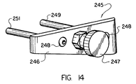
- the disconnect member 245 includes plate 246, knob 247 and shafts 249, 251.
- Knob 247 extends outwardly from the front side of plate 246 and is used to turn a threaded bolt on the other side of the plate 246.
- Shafts 249, 251 are attached to the back side of plate 246 with bolts 248 and extend outwardly therefrom.
- a modified bracket 255 having a substantially I-beam shape, is secured to carriage body 22 by bolts 260, and extends downwardly therefrom. Further, mounting flange 261 is secured to the bottom web of modified bracket 255 by bolts 262. Mounting flange 261 extends downwardly from bracket 255. Mounting flange 261 includes an inverted groove, indicated generally at 263, extending along the length of the flange. Groove 263 is adapted to receive a tongue 264 on support collar 265.
- the transducer housing 48 is fitted within collar 265 and the tongue 264 of the collar 265 is received within the groove in flange 261.
- the knob 247 is turned to advance the threaded bolt into a tapped hole in the mounting flange 261 to hold the plate 246 in mounted position on mounting flange 261.
- the shafts 249, 251 of disconnect member 245 are received in cooperating bores in mounting flange 261 and tongue 264 to thereby support the transducer housing.
- Disconnect member 245 may be removed from flange 261 by reverse rotating knob 247 to remove shafts 249, 251 from the aligned bores in the tongue and mounting member. Once disconnect member 245 is removed, collar 265 can be removed from the carriage and a new collar and transducer attached. Consequently, disconnect member 245 allows the quick change of transducers for use with the ultrasonic cutting system.
- a low angle cut of the stock material can be achieved.
- the blade traverses the material without the material moving or vibrating, thereby decreasing the cutting time and increasing the quality of the cut.
- the material can be cut at a low angle to increase the surface area of the cut portion and to allow the cut surface to be substantially seamlessly bevel lap spliced to the cut surface at the other end of the stock material in the tyre building process.
- the substantially seamless splice reduces the radial forces on the splice, improves the balance of the tyre, and reduces tyre cure time. Additionally, the material savings in eliminating the end ply overlap reduces the overall cost of the tyre.
Landscapes
- Engineering & Computer Science (AREA)
- Mechanical Engineering (AREA)
- Textile Engineering (AREA)
- Life Sciences & Earth Sciences (AREA)
- Forests & Forestry (AREA)
- Perforating, Stamping-Out Or Severing By Means Other Than Cutting (AREA)
- Nonmetal Cutting Devices (AREA)
- Tyre Moulding (AREA)
Description
- This invention relates to an ultrasonic cutting apparatus for stock material, and in particular to an ultrasonic cutting apparatus for employing a blade adapted to ultrasonically cut tyre stock material at a low angle. The invention also relates to a method of ultrasonically cutting stock material.
- A tyre typically includes plies of various types, including, for example, an inner ply. These plies may be formed from a long sheet of rubber stock material by cutting the stock material to appropriate lengths and folding the end portions together to form a generally annular shape adapted to become part of a tyre carcass. The two end portions of the stock material are typically overlapped a small amount and may be bonded together, for example, by adhesively bonding, or "stitching" the end portions together under pressure. The overlap of the ply ends results in a limited circumferential portion of these plies having a slight radial build-up, which cannot be avoided with known cutting techniques.
- Currently, when a sufficient length of stock material has been prepared for cutting, the stock material is supported on a processing table and the blade is forced into the material. The blade is moved across the width of the stock material to cut off the desired length of material. The stock material is typically formed from rubber based products which are flexible and "sticky" to the touch. When the stock material is being cut with a conventional blade, the material tends to move or vibrate as the blade traverses the material, thereby increasing the cutting time and decreasing the quality of the cut. Moreover, the blade must cut the stock material at an angle substantially perpendicular to the processing table, or the stock material will tend to bunch up in front of the blade. The perpendicular angle of cut results in a cut edge having a reduced surface area, thereby making it difficult to splice the cut surfaces to one another in the tyre building process. Consequently, it is necessary to overlap the ply end portions a small amount and adhesively bond or "stitch" them together under pressure.
- Other cutting techniques are generally known but have not been successfully applied to stock material cutting. For example, ultrasonic cutting has been used for cutting textile material as shown in U.S. Patent No. 4,711,693 . This patent shows an anvil comprising an elongated, substantially rectangular housing in which a piston is disposed for motion relative to the housing. The anvil includes a slitting implement advanced by the piston. The textile material is fed through the nip between the slitting implement and ultrasonic horn. The ultrasonic horn is undergoing vibratory motion to cut the textile material held thereagainst.
- EP-A-0324199 discloses a method and apparatus for ultrasonically cutting stock material. The apparatus includes means for temporarily adhesively securing the stock material to an anvil; a carriage assembly moveable transversely across the width of the anvil; and ultrasonic cutting tool mounted on said carriage and having a cutting blade coupled thereto, the blade being capable of resonating in response to ultrasonic energy travelling longitudinally therethrough. The arrangement is such that when the carriage assembly moves transversely across the anvil, the blade cuts through and across the top of the stock material. The blade can be positioned with an angle between 10 and 90 degrees with respect to the stock material.
- EP-A-0240972, EP-A-0284761 and US-A-4516451 disclose tyres that have been cut at lob angles using known cutting methods. Additionally, it is known that attempts have been made to cut tyre sidewall material with a conventional blade at angles as small as 23° with respect to the horizontal, and then splice the cut ends together with a bevel lap splice. However, it has been found that a bevel lap splice of 23° or more in a sidewall does not adhere well without additional glues or adhesives and can become separated under normal tire operating conditions.
- According to the invention in a first aspect, there is provided an ultrasonic cutting apparatus for stock material, having an anvil, means for temporarily securing the stock material to the anvil, a carriage assembly moveable across the width of the anvil, an ultrasonic cutting tool mounted on said carriage, said cutting tool having a blade mechanically coupled thereto, said blade resonating in response to ultrasonic energy travelling longitudinally therethrough;
the ultrasonic cutting tool being mounted in respect of the anvil such that the blade extends at an angle of about 5 to 10 degrees with respect to the horizontal for stock material under 0.49 cm. thickness or, for stock material of thickness greater than 0.49 cm., at an angle such that the cut surface of the stock material has a width between about 1.00 cm. and about 2.88 cm.; and
wherein when said carriage assembly moves transversely across said anvil, said blade cuts through and across the stock material,
characterized in that:
the apparatus includes a device slidable relative to the anvil and capable of engaging the stock material positioned at a location behind said blade to separate the stock material from the anvil after the blade has cut the stock material. - Thus the invention relates to an ultrasonic cutting system having a blade adapted to ultrasonically cut stock material at a low angle. A preferred embodiment of an ultrasonic cutting system according to the invention comprises a processing table, a carriage assembly adapted to move transversely across the width of the processing table, and an ultrasonic cutting tool mounted on the carriage assembly.
- The processing table has an anvil incorporated therein. According to a preferred embodiment of the invention, the anvil comprises two parallel strips of plastic or Lexan (Registered Trade Mark) material mounted on a beam or a base.
- The parallel strips extend across the width of the anvil and define a guide channel therebetween for slidably receiving and guiding part of the carriage assembly.
- The carriage assembly of the preferred embodiment of the ultrasonic cutting apparatus is adapted to move transversely across the anvil on two stationery parallel rods positioned above the anvil. The rods respectively are received in and pass through bearing blocks, which are part of the main carriage body of the carriage assembly.
- The carriage assembly of the preferred embodiment also includes a set of rollers which are mounted on the distal ends of arms extending downwardly from the carriage body. The set of rollers include a first and second roller, wherein the second roller is located between the blade and the first roller. The rollers are adapted to travel ahead of the blade as the carriage traverses the stock material, with the first roller leading the second roller. The two rollers apply a predetermined amount of downwardly directed pressure on the stock material to removably bond or "stitch" the stock material to the anvil positioned therebelow.
- In a preferred embodiment of the invention the ultrasonic cutting apparatus is mounted on the carriage such that the blade extends at a low angle, preferably at an angle of about 5° to 10° with respect to the horizontal. The blade is also offset forwardly from the carriage assembly at an angle of approximately 15° relative to a normal or transverse plane across the carriage assembly. The low angle of the blade creates a beveled cut having a width of between about 1.00 cm and 2.88 cm. When the blade is brought into contact with the stock material, the oscillating blade cuts cleanly through the material.
- The carriage assembly may further include a substantially L-shaped shoe extending downwardly therefrom. The shoe travels behind the blade when the carriage is moving across the anvil, and is adapted to lift and remove the cut portion of +he stock material from the anvil. The bottom portion of the shoe includes a downwardly extending guide projection slidingly received in the anvil guide channel to maintain the alignment of the carriage assembly with the anvil and processing table.
- In a preferred embodiment of the invention the carriage assembly includes an ultrasonic cutting apparatus having a transducer and a cutting blade. The transducer and blade are mounted toward the side of the carriage body and extend at an angle downwardly therefrom. The cutting apparatus is part of, and moves concurrently with, the carriage assembly as it traverses the stock material. The transducer produces ultrasonic energy which is applied to the blade to create compression waves axially therealong.
- According to the invention in a second aspect, there is provided a method of ultrasonically cutting stock material comprising the steps of:
- temporarily securing the stock material to an anvil;
- mechanically coupling a blade to an ultrasonic transducer to form an ultrasonic cutting tool;
- mounting said ultrasonic cutting tool on a carriage assembly;
- resonating the blade with ultrasonic energy travelling longitudinally therethrough;
- moving the carriage assembly transversely across the width of the stock material; and
- cutting the stock material with the blade as the carriage assembly moves transversely across the width of the stock material,
- Preferably said step of cutting the stock material said step of cutting the stock material with a blade comprises cutting the stock material at an offset angle of about 0 to 15 degrees relative to an axis normal to the anvil.
- Conveniently the method includes the further step of dampening vertical oscillations of said blade.
- By providing an ultrasonic cutting system that uses ultrasonic energy to cut stock material, a low angle cut of the stock material can be achieved. The low angle cut results in a cut edge having an increased and "tacky" surface area, which facilitates splicing the cut surface of the stock material together with a bevel lap splice without using additional glues or adhesives. The bevel lap splice provides for a substantially seamless bond of the stock material and eliminates radial build-up along the seam. Moreover, the bevel lap splice improves the balance of the tyre and reduces both the radial forces on the splice and the tyre cure time. Additionally, the material savings in eliminating the end ply overlap reduces the overall cost of the tyre.
- There now follows a description of preferred embodiments of the invention, by way of example, with reference being made to the accompanying drawings, in which:
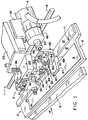
- Fig. 1 is a diagonal upstream perspective of the ultrasonic cutting system constructed according to the present invention, with the stock material and rod support structure being omitted for clarity of illustration;
- Fig. 1A is a cross-sectional side view of the overlap splice of a prior art tyre;
- Fig. 1B is a cross-sectional side view of the crush-cut splice of a prior art tyre;
- Fig. 1C is a cross-sectional side perspective view of the low angle bevel lap splice provided by the present invention;
- Fig. 2 is a side, upstream perspective view of the ultrasonic cutting system;
- Fig. 3 is a plan view of the carriage assembly shoe taken along the plane 3-3 of Fig. 2;
- Fig. 4 is a side view of the shoe taken along the plane 4-4 of Fig. 3;
- Fig. 5 is a diagonal downstream perspective of the ultrasonic cutting system;
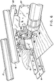
- Fig. 6 is a diagonal downstream perspective of the ultrasonic cutting system, similar to but enlarged from Fig. 5, showing the blade ultrasonically cutting the stock material;
- Fig. 7 is a diagonal downstream perspective of the ultrasonic cutting system taken from a different angle, showing the blade ultrasonically cutting the stock material;
- Fig. 8A is an elevation of the cutting apparatus of the ultrasonic cutting system with the transducer and suspension assembly being shown in hidden lines;
- Fig. 8B is a detailed side view partially in section of the cutting apparatus, similar to but enlarged from Fig. 8A, having the housing removed for clarity;
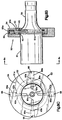
- Fig. 8C is an end elevation of the cutting apparatus taken along the plane 8C-8C of Fig. 8B;
- Fig. 9 is a perspective view of an alternative anvil embodiment;
- Fig. 10 is an end elevation of the anvil of Fig. 9 showing the details of the stock material stripper bar;
- Fig. 11 is a side upstream perspective view of an additional embodiment of the ultrasonic cutting system;
- Fig. 12 is a diagonal downstream perspective of the ultrasonic cutting system of Fig. 11;
- Fig. 13 is a diagonal downstream perspective of the ultrasonic cutting system of Fig. 12, with portions removed for clarity and with a blade stabilizing assembly added; and
- Fig. 14 is schematic elevation of the disconnect member of the quick connection system for the cutting tool.
- This invention relates to an ultrasonic cutting system, indicated generally at 1, having an ultrasonically energized blade adapted to cut stock material at a low angle. As shown in Figs. 1, 2 and 5, an ultrasonic cutting system 1 according to the prevent invention comprises a processing table, indicated generally at 2, a carriage assembly adapted to move transversely across the width of the processing table, indicated generally at 3, and an ultrasonic cutting tool mounted on the carriage assembly, indicated generally at 4.
- The processing table 2 of the cutting system is normally located in a stock material processing line. The processing table 2 supports the stock material as it is fed from the stock material supply through the cutting station. At the cutting station, the stock material is cut into lengths, which are then formed into a tire ply for incorporation into a green tire as it is being built.
- As shown in Fig. 1, the processing table 2 includes a feed table 6 and an anvil, indicating generally at 7, mounted in end to end relationship to one another. In one embodiment, the
anvil 7 includes, abase 8, a front strip 9 and aback strip 10 of plastic or Lexan (Registered Trade Mark) material. Theseparallel strips 9, 10 extend across the width of thebase 8 and are secured to the top of thebase 8 by screws or other conventional means. The parallel strips extend across theanvil 7 in close proximity to one another to form a guide channel therebetween, as shown at 12. The top surfaces ofstrips 9 and 10 preferably lie in a common plane with the top surface of feed table 6. - The feed table 6 may include a conveyor for automatically advancing
stock material 13 to the anvil at the cutting station. Thestock material 13 is advanced in the longitudinal direction ofarrow 14, with the term "upstream" meaning to the left of the cutting station, and the term "downstream" meaning to the right of the cutting station, as viewed in Fig. 1. Thestock material 13 downstream of the cutting station may be supported by arotatable shaft 15 as shown in Fig. 7, or by a downstream, run-out table (not shown). Theshaft 15 or run-out table form part of the overall processing table. - As shown best in Fig. 5, the
carriage assembly 3 of the ultrasonic cutting system is adapted to move transversely across theanvil 7 on two parallel and transversely extendingrods blocks carriage assembly 3 to selectively move along therods stock material 13. The lateral movement of the carriage assembly along the rods is controlled by a conventional motor, such as a servo motor (not shown), which can be either mounted on or near the table or on the carriage assembly. - The
carriage assembly 3 further includes acarriage body 22, as best shown in Fig. 5. Thecarriage body 22 extends transversely between and is fixedly secured to the bottom of bearing blocks 19 and 20. - A vertically extending
hanger 23 is connected to and extends downwardly from the upstream end of thecarriage body 22. Asupport plate 24 is secured to and extends horizontally outwardly from the bottom ofhanger 23. Thesupport plate 24 can be selectively transversely adjusted relative tohanger 23. For this purpose, and as best shown in Fig. 5, the hanger has elongatedslots 26 therein respectively receivingbolts 27 on the support plate to allow selective transverse adjustment of thesupport plate 24 relative to thehanger 23.Nuts 25 onbolts 27 may be selectively drawn down against vertically extendinghanger 23 to secure thesupport plate 24 in the selected transverse position relative to the vertically extendinghanger 23. - As shown in Fig. 2, the
support plate 24 has aroller support flange 29 secured to the upstream end thereof. The vertically extendingflange 29 may be transversely adjusted relative to thesupport plate 24. For this purpose, spacedbolts 31 on the upstream end of thesupport plate 24 are received in a horizontal, elongatedslot 32 in the upper end offlange 29.Nuts 30 onbolts 31 may be selectively drawn down againstbackup member 33 to secure theroller support flange 29 in the selected transverse position relative to supportplate 24. - The
support flange 29 has afirst roller shaft 35 mounted thereon adjacent the bottom thereof.Roller shaft 35 extends through a mounting hole insupport flange 29 and is secured thereto to mountroller shaft 35 above and in a parallel relationship to strip 10 ofanvil 7. A first, relativelywide roller 36 is rotatably mounted onshaft 35. Theroller 36 preferably has a number of outwardly extending ribs extending circumferentially therearound. Thefirst roller 36 applies pressure to thestock material 13 positioned between thefirst roller 36 and theanvil 7, as will be described in more detail hereinafter. - As shown in Fig. 1, the
support plate 24 has a plurality of tappedholes 37 extending therethrough to selectively receive a threadedshaft 38 in the selected position relative to the anvil. The height of the shaft may be adjusted upwardly or downwardly relative to supportplate 24 by turning the shaft in one direction or the other. As shown in Fig. 2, the bottom ofshaft 38 has ayoke 39 mounted thereon which extends downwardly therefrom. Theyoke 39 includes two parallel and downwardly extendingarms second roller shaft 42 extends between and is mounted to downwardly extendingarms roller shaft 42 is above and in parallel relationship to thestrip 10 ofanvil 7. A second, relativelynarrow roller 43 is rotatably mounted onsecond roller shaft 42. Thesecond roller 43 applies concentrated, downwardly directed pressure to thestock material 13 positioned between thesecond roller 43 and theanvil strip 10, as will be described in more detail hereinafter. - The
rollers shaft 38, aspring 44 can be inserted between theyoke 39 andsupport plate 24 to biasroller 43 downwardly toward the anvil. Thespring 44 is adapted to maintain a predetermined downward pressure on theanvil 7, yet be flexible enough to allow the yoke to be raised to insert the stock material between thesecond roller 43 and the anvil. - As shown in Fig. 1, the
rollers back strip 10 ofanvil 7, on the side closest to thecarriage guide channel 12. As thecarriage assembly 3 moves transversely across theanvil 7, eachroller strip 10 with the inside edges of the rollers being in alignment with the inside edge of thestrip 10. The rollers are located at a position on the carriage assembly such that thefirst roller 36 is adapted to provide the initial, general stitching of thestock material 13, while thesecond roller 43 is adapted to provide a localized stitch of thestock material 13, just slightly ahead of ablade 46 on theultrasonic cutting tool 4. - The first and second rollers provide sufficient downward pressure on the
stock material 13 to temporarily bond or "stitch" the material to theanvil 7. Thestock material 13 is typically formed from petroleum-based products which are "sticky" or "tacky" to the touch, and hence can be temporarily adhesively bonded to a surface. Adhesively bonding the stock material just ahead of the blade permits theblade 46 to traverse the stock material at a low angle without the material moving or vibrating. Moreover, after theblade 46 has traversed thestock material 13, the material may be easily removed from the processing table by merely "peeling" it away. - As shown in Fig. 8A, the
blade 46 has sharpened edges and is mechanically coupled to a transducer, indicated generally at 47, within ahousing 48. Thetransducer 47,blade 46 andhousing 48 together cooperatively form anultrasonic cutting tool 4 which is mounted toward the side of thecarriage assembly 3. The cutting tool moves concurrently with thecarriage assembly 3 as it traverses the stock material. - The
transducer 47 consists of a crystal stack, indicated generally at 50, and ahorn 51 which are coupled together by a stud bolt (not shown). Thestack 50 andhorn 51 are mounted within thetransducer housing 48 by a suspension assembly, indicated generally at 53, which insulates the housing from the ultrasonic energy. As shown in detail in Fig. 8B, thesuspension assembly 53, for example, includes anouter ring 54, aninner ring 52 and two O-rings 45, disposed between the inner ring and opposite sides offlange 51a on the horn. The outer ring has four tapped bores 65A (Fig. 8C) therein spaced 90° apart from one another. The four tapped bores 65A are respectively in radial alignment with four circumferentially spaced bores 65B ininner ring 52 and four circumferentially spaced bores 65C in thehorn 51. - As shown in Fig. 8C, four pins, indicated generally at 66, disposed 90° apart from each other, extend radially inward in aligned bores 65A-C from the
outer ring 54 into thehorn 51. Thepins 66 have threaded heads 66A at their radially outer ends to allow the pins to be held in position by the threaded connection between the heads 66A and the tapped bores 65A. This threaded connection on the pins secures thesuspension assembly 53 to thehorn 51 and prevents thehorn 51 from rotating within thesuspension assembly 53. - The outer ends of the heads 66A of
pins 66 are received within the confines of bores 65A to help prevent ultrasonic energy loss through the pins to thesuspension assembly 53. Further, thesuspension assembly 53 is located at a position along thetransducer 47 that corresponds to an ultrasonic energy nodal point, such that a minimum amount of energy is lost by transmission through thesuspension assembly 53. - The
horn 51 of thetransducer 47 extends forwardly from its coupling with the stack and narrows down to a forward necked end, shown generally at 55 in Fig. 8A, a portion of which protrudes from the transducer housing. A holder 55a is mechanically coupled to thenecked end 55 by a stud bolt (not shown). The holder 55a has a blind end bore (not shown) in the forward end which is adapted to receive the rear end ofblade 46. Theblade 46 is mechanically soldered within the blind end bore by conventional processes. - The
crystal stack 50 is ultrasonically driven by a set of piezo-electric crystals, shown generally at 56, which are located at the end of thecrystal stack 50 and which are mechanically coupled thereto bycompression bolt 56a. Thecrystals 56 are typically formed from PZT8 material. Thecrystal stack 50 is of the type commercially available, such as that available from Branson Ultrasonics. - In the preferred form of the invention, the
crystals 56 are driven with square waves and are adapted to produce oscillations in the 40 Khz range in the crystal stack. The oscillations produce ultrasonic compressive energy waves axially down thecrystal stack 50,horn 51 and holder 55a, and subsequently down theblade 46. Thehorn 51 can be tuned so that the ultrasonic energy produces standing waves along theblade 46 having a maximum near the point that the blade is adapted to enter thestock material 13. Accordingly, when theblade 46 contacts the stock material, the oscillating blade cleanly cuts through the material. - As shown in Fig. 6, the
ultrasonic cutting tool 4 is fixedly mounted to thecarriage assembly 3 bybracket 57.Bracket 57 has a collar, which extends circumferentially around and supports the housing of the transducer. Theultrasonic tool 4 is mounted to thecarriage assembly 3 such that theblade 46 extends outwardly from the horn 51 (Fig. 8) at a low angle, preferably at angle of about 5° to 10° with respect to the horizontal, as represented by angle A in Fig. 6. It has been found that, for stock material having thicknesses of up to 0.28 cm, mounting thecutting tool 4 on thecarriage assembly 3 at an angle A of about 5° to 8° results in a preferred cut of thestock material 13. For stock material of thicknesses up to 0.49 cm, an angle A of about 8° to 10° is preferable. For stock material thicker than 0.49 cm, the angle A should be set so that the width of the cut surface of the stock material is between about 1.00 cm and 2.88 cm. Additionally, as best shown in Fig. 3, theblade 46 extends at an angle offset from an axis normal to the anvil by about 0° to 15°, and preferably at an angle of about 15°, to achieve an enhanced cutting system for most stock materials. This angle is illustrated at B in Fig. 3. - The low angle of the
blade 46 relative to the horizontal creates a beveled cut having a width of between about 1.00 cm and 2.88 cm. The wide cut is extremely tacky which allows the freshly cut end portion to be applied to another cut end portion to create a high strength bevel lap splice without end ply overlap. Conventional splicing techniques result in a tire having an inner ply wherein the two end portions have an overlapped portion, as shown indicated generally at "C" in Fig. 1A, or a crush-cut portion, as indicated generally at "D" in Fig. 1B. However, the bevelled cut provided by the present invention provides for a tire having an inner ply wherein the two portions of the material substantially seamlessly bonded together to provide a circumferentially continuous ply of stock material, as indicated generally at "E" in Fig. 1C. - As shown in Fig. 1, the
carriage assembly 3 further includes an L-shaped shoe, indicated generally at 58, extending downwardly therefrom. Theshoe 58 is mounted transversely behindblade 46 and thus travels immediately behind theblade 46 when thecarriage assembly 3 is moving across theanvil 7. Theshoe 58 has a substantially wedge-shapedupper surface 59 with rearwardly tapered and flared edges 60.Shoe surface 59 is adapted to slide between thestock material 13 and theanvil 7, thereby lifting and separating the material from the table as will be described in more detail below. - The
shoe 58 is mounted from asuspension arm 61 extending downwardly fromsupport plate 24. A generally L-shape bracket 62 can be selectively longitudinally adjusted relative to thearm 61. For this purpose, thebracket 62 has a slot 63 in one leg thereof to receivebolt 64 onarm 61.Nut 65 onbolt 64 may be selectively drawn down against the bracket to secure the bracket in the selected longitudinal position relative to thearm 61 andcarriage body 22. Theshoe 58 is bolted to the other leg ofbracket 62. - The
bottom portion 67 of theshoe 58 forms a flat surface that is adapted to slide along the top surfaces ofstrips 9 and 10 onanvil 7. As shown in Figs. 3 and 4, thebottom portion 67 of theshoe 58 includes a generally centrally positionedguide projection 68 fixedly attached to and extending downwardly therefrom. Theprojection 68 is slidingly received in theguide channel 12 defined in theanvil 7. Theguide projection 68 sliding inguide channel 12 maintains the alignment of the shoe andcarriage assembly 3 with respect to theanvil 7 andstock material 13. - The forward end of the
guide projection 68 has ablade rest 69 mounted thereon and extending upwardly therefrom. The blade rest is preferably formed from a Teflon (Registered Trade Mark) material and has a pocket formed therein. As best shown in Fig. 3, the free end of the blade is received in the pocket portion of theblade rest 69. Both theblade 46 and theblade rest 69 are designed to move in unison across the processing table with the carriage assembly. Anchoring the end ofblade 46 in theblade rest 69 prevents damaging oscillations of the free end of the blade that could result in cracking or breakage. - In the materials processing line, shown in Fig. 1, the
stock material 13 is brought along the processing table 2 until the desired amount of material stretches over, and is downstream of, theanvil 7. High frequency energy is then applied to thecutting tool 4 to produce ultrasonic waves within thecrystal stack 50,horn 51 andholder 51a, (Fig. 8A), and consequently compression forces axially along the length of theblade 46. As shown in Figs. 5 and 7, thecarriage assembly 3 is moved across thestock material 13 with the tworollers blade 46. The downward pressure of therollers stock material 13 causes the material to be temporarily adhesively bonded to theanvil 7, particularly in the area immediately in front of the blade. - As the
blade 46 passes through thestock material 13, the angle of the blade creates a bevelled cut having a width of approximately 1 cm from the edge of the cut. Thecarriage assembly 3 traverses thestock material 13 until the blade finishes its cut and reaches the opposite end. Typically, theblade 46 takes longer to traverse the thicker portions of the stock material than the thinner portions of the material. - In the preferred form of the invention, as shown in Fig. 6, as the blade cuts through the stock material, the
upper surface 59 of trailingshoe 58 lifts the back portion of thecut stock material 13 away from its adhesive bond with theanvil 7. Thesurface 59 and the flarededge 60 also peels or bends the material away from the cut, as schematically illustrated in Fig. 6. The forward, cut length of thestock material 13 is either manually or automatically removed from the table and processed into the finished tire, while the uncut portion of thematerial 13 is moved down the processing table to be positioned for another cut. - In another embodiment of the invention, the number of stitching rollers may be increased. The additional rollers may, for example, extend downwardly from additional holes in support plate 24 (Fig. 1) and be located at selected positions along the
strip 10 of theanvil 7. For example, a series of up to seven rollers can be used, with four of the rollers positioned ahead of the blade. Additionally, a fifth roller can be located substantially on top of the blade, and a sixth and seventh roller can be positioned behind the blade. At least two of the rollers, one in front of the blade and one in back of the blade, are vertically aligned with the inside edge of the back strip of the anvil. Moreover, the leading two rollers may be toed-in, and the last two rollers may be toed-out, to stretch the stock material during the cutting process and further enhance the cutting efficiency. - The use of additional rollers increases the area of temporary adhesive bonding of the stock material to the anvil. However, it has been found that, by using two
rollers roller 43 located directly in front of the blade, a sufficient bond of the stock material to the anvil is achieved to obtain the desired cut. - Further, both the front and rear strips of the
anvil 7 may include a number of holes (not shown) spaced therealong which are adapted to draw a vacuum therethrough. The holes are spaced uniformly over the length of either (or both) the front and back strips 9, 10 on theanvil 7. When thestock material 13 is laid over theanvil 7, a vacuum is applied to the bottom of the stock material to securely bond the material to the anvil. This bonding by vacuum may be further enhanced by clamps to compress the stock material against the anvil. Hence, when theblade 46 traverses the stock material, the aforementioned cut may be made on stock material securely held to the anvil. - In another embodiment, as shown in Figs. 9 and 10, the anvil comprises a substantially T-shaped
member 72 located immediately adjacent the end of the feed table 6. The T-shapedmember 72 is adapted to be moved vertically relative to the processing table. The T-shapedmember 72 has achannel 73 formed in the top side thereof and extending thereacross. Thischannel 73 receives a Lexan (Registered Trade Mark)plastic strip 74 along the cutting axis. Alternatively,channel 73 may be used as a guide channel cooperating with the projection on the carriage assembly shoe. - The T-
shape member 72 includes a steppedslot 75 in its top surface parallel to and closely spaced fromchannel 73. The steppedslot 75 extends from adjacent one end of the upper web ofmember 72 to adjacent its other end. Theslot 75 passes entirely through the upper web of T-shapedmember 72. - Stepped
slot 75 receives a T-shape stripper bar 77 therein, with the stripper bar being supported by its shoulders resting on the step ofslot 75, as best shown in Fig. 10.Pins 78 extend downwardly from the bottom ofstripper bar 77. When the T-shaped member orbase 72 is lowered bypiston cylinder assemblies 79, thepins 78 engage a fixedstop bar 80 positioned therebelow. As thebase 72 descends further, thestripper bar 77 is "elevated" relative to the upper surface of the base to strip the stock material thereon from the base. - In still another embodiment of the invention, as shown in Fig. 11, a
spacer 100 is connected to and extends downwardly from the upstream end of thecarriage body 22.Hanger 105 is connected to and extends downwardly fromspacer 100. Asupport plate 110 is secured to and extends downwardly from the bottom ofhanger 105. Thesupport plate 110 can be selectively transversely adjusted relative tohanger 105. For this purpose, thehanger 105 has elongatedslots 115 therein respectively receivingbolts 117 to allow selective transverse adjustment of thesupport plate 110 relative to thehanger 105.Bolts 117 have nuts (not shown) which may be selectively drawn up against the bottom ofsupport plate 110 to secure the horizontally extendingsupport plate 110 in the selected transverse position relative to thehanger 105. - Additionally, as shown in Fig. 11, a horizontally and transversely extending
roller support flange 120 is secured to the top surface of thecarriage body 22. Thesupport flange 120 may be transversely adjusted relative to thecarriage body 22. For this purpose, spacedbolts 125 are received inelongated slots 127 throughsupport flange 120.Bolts 125 may be selectively drawn down againstflange 120 to secure theroller support flange 120 in the selected transverse position relative to thecarriage body 22. - The
support flange 120 has a downwardly extending first threadedshaft 130 received in a bore at one end of the support flange. Anut 135 can be threaded onto the threadedshaft 130 and bears against the upper surface ofsupport flange 120. The position of the nut controls the vertical position of theshaft 130 relative to supportflange 120.Shaft 130 extends downwardly and has a roller support bracket, shown generally at 140, mounted to its lower end. - A
spring 145 may be located onshaft 130 betweensupport flange 120 androller support bracket 140.Spring 145 biases the roller support bracket away fromsupport flange 120 to bringnut 135 into engagement withsupport bracket 120. -
Roller support bracket 140 further includes two downwardly extendingparallel arms Roller shaft 150 extends through aligned mounting holes in the arms ofroller support bracket 140.Shaft 150 is secured to the respective arms bynuts 154 threaded onto the opposite free ends ofshaft 150. The shaft is above and in parallel relationship to strip 10 ofanvil 7. Awide roller 155, is rotatably mounted onshaft 150 and provides downward pressure to the stock material. - Further,
roller support bracket 140 is vertically guided to maintain proper alignment with theanvil 7. For this purpose,guide stud 168a extends longitudinally throughsupport plate 110. The outer ends of the guide stud are received in a vertically extendingslot arms spacer washer 170 is received on one end ofguide stud 168a between the outside edge of downwardly extendingarm 148 and the one head ofstud 168a. Similarly,spacer washer 169 is received on the other end ofstud 168a between the outside edge of downwardly extendingarm 147, and a second head ofstud 168a. Additionally,spacer 171 is received onstud 168a and extends between thesupport plate 110 and the inside edge of downwardly extendingarm 147. - The guide stud, spacers and the sliding attachment of
shaft 130 withsupport flange 120, thereby maintains the vertical alignment of the roller support bracket, and hence with respect toanvil 7. Theroller support bracket 140 is biased downwardly towardanvil 7 byspring 145. The spring is adapted to maintain a predetermined downward pressure on theanvil 7, yet be flexible enough to allow the roller support bracket, and henceshaft 130 andnut 135, to be raised to insert the stock material between the roller and the anvil. - A
second roller 43 is mounted to and extends downwardly from thesupport plate 110. The construction of second roller assembly in this embodiment is substantially the same as the construction described in connection with the first embodiment. - Still further, as shown in Figs. 11, an L-shaped shoe, indicated generally at 180, is mounted from a
suspension arm 185 by a plate 190 (Fig. 13).Suspension arm 185 is received ingroove 186 ofhanger 105, extends downwardly therefrom and may be adjusted longitudinally relative tohanger 105.Plate 190 can be fastened to thesuspension arm 185 by conventional fasteners, such as by nuts and bolts. For this purpose, as shown in Fig. 13, spacedbolts 192 pass through bores inplate 190 into tapped holes insuspension arm 185 in alignment therewith. - Similarly, the
shoe 180 can be mounted to the bottom ofplate 190. For this purpose,plate 190 has a plurality ofelongated slots 194 passing therethrough.Bolts 193 pass throughslots 194 into tapped holes in the vertical arm ofshoe 180. Theslots 194 allow the shoe to be vertically adjusted relative to theplate 190. This vertical adjustment may be closely controlled by an eccentric adjustment mechanism. - The eccentric adjustment mechanism includes an
elliptical drive shaft 195 that extends through an oversized bore inplate 190 into acircular opening 198 in the vertical leg ofshoe 180. As the elliptical drive shaft is turned, the surface thereof cammingly engages theopening 198 to raise or lower theshoe 180. When the proper shoe position is obtained (preferably providing a clearance of approximately 0.08mm (3/1000 of an inch) between the bottom of the shoe and the anvil), the shoe-is tightly secured. - For this purpose, the
elliptical drive shaft 195 has a threadedshank 196 on its downstream end. Awasher 197 is positioned onshank 196. For locking, the washer is drawn against theplate 190 by nuts 199. Thebolts 193 are then tightened against the plate to complete the rigid mounting ofshoe 180 toplate 190 in its selected vertical position. - The
shoe 180 includes a bottom portion, indicated generally at 200 and shown in Fig. 11. This shoe is substantially the same in design and function as thebottom portion 67 ofshoe 58 in the first embodiment as described herein. Specifically, thebottom portion 200 ofshoe 180 includes awedge shape surface 59, ablade rest 69 and aguide projection 68 extending therebetween and connected thereto. The bottom portion has a roller assembly 205 attached thereto. Roller assembly 205 preferably includes, for example, threerollers 205a, 205b, 205c, mounted within abracket 207. Rollers 205a-205c extend in a co-planar relationship along the side of thebottom portion 200 ofshoe 180. The rollers increase in diameter as they get closer to thewedge shape surface 59. Each roller has an axle extending therethrough which is rotatably attached to opposing sides ofbracket 207. Thebracket 207 in turn is attached to the side of thebottom portion 200. - The three rollers are adapted to facilitate the removal of the stock material from its adhesive bond with the anvil. The stock material tends to removably adhere to the rollers and consequently "ride up" the rollers and onto the shoe during rotation of the rollers. By increasing the diameter of the rollers and having the top surface of rollers 205c positioned above the leading edge of the wedge shape stripping surface, the
material 13 is easily removed by the shoe passing between the anvil and the material. - Additionally, as shown in Fig. 13, a blade stabilization assembly, shown generally at 209, having spring-loaded
teflon button 210 can be included with the carriage assembly to minimize the possibility of the blade either cracking or breaking. Theteflon button 210 is adapted to engage the top surface ofblade 46 to damp out potentially damaging vertical vibrations of the blade. Theteflon button 210 extends through a bore inbracket 215 and is secured thereto, as shown at 217.Bracket 215 is pivotally connected toholder 219, which in turn is removably attached toshoe 180 bybolts 220.Holder 219 includes an outwardly extendingtongue member 225.Bracket 215 has a yoke comprising twoarms tongue member 225. Thearms tongue member 225 by a horizontally extendingpivot bolt 230.Bolt 230 is received in a fist set of cooperating and aligned holes inarms member 225. - Additionally, a second set of cooperating holes are provided in
arms member 225 to maintain the horizontal alignment of thebracket 215 with respect to the anvil, and to maintain a predetermined downwardly directed pressure on the blade. For this purpose, akey pin 232 is adapted to be received in the second set of holes whenbracket 215 andmember 225 are horizontally aligned. Whenkey pin 232 is inserted in the second set of holes,bolt 230 and pin 232 maintain the horizontal alignment of thebracket 215 with themember 225, and hence theanvil 7.Pin 232 is adapted to be removed to allow thebracket 215 to be pivoted aroundpivot bolt 230. Thebutton 210 can thus be pivoted away from its engagement with theblade 46 to facilitate repairs to the blade or to the teflon button. Accordingly, whenkey pin 232 is inserted within the second set of holes inarms member 225, the spring-loadedteflon button 210 is adapted to contactblade 46 and limit the vertical vibrations of the oscillating blade, to thereby increase the precision of the cut. Moreover, thebutton 210 increases the life of the blade by minimizing vibrations that can cause metal fatigue. - Additionally, as shown in Fig. 12, the ultrasonic cutting tool may include a quick connect system, indicated generally at 240, wherein a failed transducer can be quickly replaced, or an operating transducer can be accurately adjusted to a selected angle at a location separate from the cutting system, and then quickly fitted into place on the
carriage body 22. As shown in Fig. 14, the quick connect system includes a disconnect member, indicated generally at 245. Thedisconnect member 245 includesplate 246,knob 247 andshafts Knob 247 extends outwardly from the front side ofplate 246 and is used to turn a threaded bolt on the other side of theplate 246.Shafts plate 246 withbolts 248 and extend outwardly therefrom. - In the quick connect system, a modified
bracket 255, having a substantially I-beam shape, is secured tocarriage body 22 bybolts 260, and extends downwardly therefrom. Further, mountingflange 261 is secured to the bottom web of modifiedbracket 255 bybolts 262. Mountingflange 261 extends downwardly frombracket 255. Mountingflange 261 includes an inverted groove, indicated generally at 263, extending along the length of the flange.Groove 263 is adapted to receive atongue 264 onsupport collar 265. - To support the transducer on the carriage body, the
transducer housing 48 is fitted withincollar 265 and thetongue 264 of thecollar 265 is received within the groove inflange 261. Theknob 247 is turned to advance the threaded bolt into a tapped hole in the mountingflange 261 to hold theplate 246 in mounted position on mountingflange 261. In such position, theshafts disconnect member 245 are received in cooperating bores in mountingflange 261 andtongue 264 to thereby support the transducer housing.Disconnect member 245 may be removed fromflange 261 by reverserotating knob 247 to removeshafts disconnect member 245 is removed,collar 265 can be removed from the carriage and a new collar and transducer attached. Consequently,disconnect member 245 allows the quick change of transducers for use with the ultrasonic cutting system. - By providing an ultrasonic cutting system that uses ultrasonic energy to cut stock material, a low angle cut of the stock material can be achieved. With the stock material adhesively bonded to the anvil, the blade traverses the material without the material moving or vibrating, thereby decreasing the cutting time and increasing the quality of the cut. Further, the material can be cut at a low angle to increase the surface area of the cut portion and to allow the cut surface to be substantially seamlessly bevel lap spliced to the cut surface at the other end of the stock material in the tyre building process. Moreover, the substantially seamless splice reduces the radial forces on the splice, improves the balance of the tyre, and reduces tyre cure time. Additionally, the material savings in eliminating the end ply overlap reduces the overall cost of the tyre.
characterised by the inclusion of the step of engaging a device slidable relative to the anvil with the stock material positioned at a location behind said blade, to separate the stock material from the anvil after the blade has cut the stock material.
Claims (7)
- An ultrasonic cutting apparatus (1) for stock material, having an anvil (7), means (36, 43) for temporarily securing the stock material (13) to the anvil (7), a carriage assembly (3) moveable across the width of the anvil, an ultrasonic cutting tool (4) mounted on said carriage, said cutting tool having a blade (46) mechanically coupled thereto, said blade resonating in response to ultrasonic energy travelling longitudinally therethrough;
the ultrasonic cutting tool (4) being mounted in respect of the anvil (7) such that the blade (46) extends at an angle of about 5 to 10 degrees with respect to the horizontal for stock material under 0.49 cm. thickness or, for stock material of thickness greater than 0.49 cm., at an angle such that the cut surface of the stock material has a width between about 1.00 cm. and about 2.88 cm.; and
wherein when said carriage assembly (3) moves transversely across said anvil, said blade (46) cuts through and across the stock material (13),
characterized in that:
the apparatus includes a device (58) slidable relative to the anvil and capable of engaging the stock material positioned at a location behind said blade (46) to separate the stock material (13) from the anvil (7) after the blade has cut the stock material. - An ultrasonic cutting apparatus for stock material as claimed in Claim 1, wherein said means (36,43) for temporarily adhesively securing the stock material comprises at least one pressure roller (36, 43) mounted on said carriage assembly (3) to secure the stock material (13) to said anvil (7) at a location in front of said blade (46).
- A ultrasonic cutting apparatus for stock material as claimed in any preceding claim, wherein said anvil (7) includes a vacuum for temporarily securing the stock material (13) to the anvil (7).
- An ultrasonic cutting apparatus for stock material as in any preceding claim, wherein said blade (46) is offset at an angle of about 0° to 15° relative to an axis normal to the anvil (7).
- A method of ultrasonically cutting stock material comprising the steps of:temporarily securing the stock material to an anvil (7);mechanically coupling a blade (46) to an ultrasonic transducer (47) to form an ultrasonic cutting tool (4);mounting said ultrasonic cutting tool on a carriage assembly (3);resonating the blade (46) with ultrasonic energy travelling longitudinally therethrough;moving the carriage assembly (3) transversely across the width of the stock material (13); andcutting the stock material (13) with the blade (46) as the carriage assembly moves transversely across the width of the stock material (13),the step of cutting the stock material (13) with a blade (46) comprising cutting the stock material (13) at an angle of about 5 to 10 degrees relative to the horizontal for stock material under 0.49 cm. thickness or, for material of thickness greater than 0.49 cm., at an angle such that the cut surface of the stock material (13) has a width of between about 1.00 cm. and 2.88 cm,
characterised by the inclusion of the step of engaging a device (58) slidable relative to the anvil (7) with the stock material positioned at a location behind said blade, to separate the stock material from the anvil (7) after the blade has cut the stock material. - A method ultrasonically cutting stock material as claimed in claim 5, wherein said step of cutting the stock material (13) with a blade (46) comprises cutting the stock material (13) at an offset angle of about 0 to 15 degrees relative to an axis normal to the anvil (7).
- A method for ultrasonically cutting stock material as claimed in Claim 5 or Claim 6, including a further step of dampening vertical oscillations of said blade (46).
Applications Claiming Priority (2)
| Application Number | Priority Date | Filing Date | Title |
|---|---|---|---|
| US606715 | 1990-10-31 | ||
| US07/606,715 US5265508A (en) | 1990-10-31 | 1990-10-31 | Ultrasonic cutting system for stock material |
Publications (3)
| Publication Number | Publication Date |
|---|---|
| EP0483973A2 EP0483973A2 (en) | 1992-05-06 |
| EP0483973A3 EP0483973A3 (en) | 1992-10-28 |
| EP0483973B1 true EP0483973B1 (en) | 1996-11-20 |
Family
ID=24429162
Family Applications (1)
| Application Number | Title | Priority Date | Filing Date |
|---|---|---|---|
| EP91308908A Expired - Lifetime EP0483973B1 (en) | 1990-10-31 | 1991-09-27 | Ultrasonic cutting system for stock material |
Country Status (6)
| Country | Link |
|---|---|
| US (1) | US5265508A (en) |
| EP (1) | EP0483973B1 (en) |
| JP (1) | JP2622447B2 (en) |
| CA (1) | CA2049659C (en) |
| DE (1) | DE69123222T2 (en) |
| MX (1) | MX9101849A (en) |
Families Citing this family (35)
| Publication number | Priority date | Publication date | Assignee | Title |
|---|---|---|---|---|
| FR2689436B1 (en) * | 1992-04-07 | 1996-05-24 | Linder Ets | METHOD AND DEVICE FOR CUTTING TEXTILE MATERIALS BY ULTRASOUND. |
| JP2645798B2 (en) * | 1993-07-16 | 1997-08-25 | 三ツ星ベルト株式会社 | Rubber molded article cutting apparatus and cutting method |
| EP0865882A3 (en) * | 1997-03-20 | 1999-05-06 | Cooper Tire & Rubber Company | Ultrasonic skiver for unvulcanized rubber material |
| US6510773B1 (en) | 1998-10-20 | 2003-01-28 | The Goodyear Tire And Rubber Company | Method and apparatus for cutting elastomeric materials |
| US6592704B1 (en) | 1999-03-03 | 2003-07-15 | The Goodyear Tire & Rubber Company | Forming splice joints for elastomeric materials |
| EP1159123B1 (en) * | 1999-03-03 | 2003-01-15 | The Goodyear Tire & Rubber Company | Forming splice joints for elastomeric materials |
| US6755105B2 (en) | 2001-06-01 | 2004-06-29 | The Goodyear Tire & Rubber Company | Method and apparatus for cutting elastomeric materials and the article made by the method |
| US6790301B2 (en) * | 2001-10-15 | 2004-09-14 | The Goodyear Tire And Rubber Company | Method and apparatus for making a tread-belt assembly |
| DE10210075B4 (en) * | 2002-03-08 | 2008-04-30 | Stapla Ultraschall-Technik Gmbh | Device for sealing and separating a pipe section |
| US20050081692A1 (en) * | 2003-10-20 | 2005-04-21 | Kraft Foods Holdings, Inc. | Ultrasonic slitter |
| US8495943B2 (en) * | 2004-04-22 | 2013-07-30 | The Boeing Company | Anvil for supporting cuts in sheet and roll stock |
| DE102004022313B3 (en) * | 2004-05-04 | 2005-10-20 | Stapla Ultraschalltechnik Gmbh | Apparatus and method for fluid-tight sealing welding of a pipe section |
| US20060070504A1 (en) * | 2004-10-01 | 2006-04-06 | Downing Daniel R | Apparatus for cutting elastomeric materials |
| JP2008515648A (en) * | 2004-10-08 | 2008-05-15 | ソシエテ ド テクノロジー ミシュラン | Cutting pre-assembled rubber products |
| US7524398B2 (en) * | 2004-12-23 | 2009-04-28 | The Goodyear Tire & Rubber Company | Apparatus for making tire components, and a tire |
| US7455002B2 (en) * | 2004-12-23 | 2008-11-25 | The Goodyear Tire & Rubber Company | Method for cutting elastomeric materials and the article made by the method |
| US8561511B2 (en) * | 2004-12-23 | 2013-10-22 | The Goodyear Tire & Rubber Company | Anvil with vacuum width adjustment |
| US20060137814A1 (en) * | 2004-12-23 | 2006-06-29 | Downing Daniel R | Method for making reinforced elastomeric materials |
| US20060137804A1 (en) * | 2004-12-23 | 2006-06-29 | Downing Daniel R | Method for making tire ply |
| US20060229184A1 (en) * | 2005-04-07 | 2006-10-12 | Hewlett-Packard Development Company, L.P. | Creaser |
| US8166857B2 (en) | 2005-07-01 | 2012-05-01 | Hewlett-Packard Development Company, L.P. | Perforator |
| JP2007038367A (en) * | 2005-08-04 | 2007-02-15 | Seiko Instruments Inc | Sheet material cutting unit and printing apparatus |
| US20100212470A1 (en) * | 2006-10-17 | 2010-08-26 | Kazumasa Ohnishi | Disklike cutting tool and cutting device |
| DE102008056372A1 (en) * | 2008-10-27 | 2010-04-29 | Harburg-Freudenberger Maschinenbau Gmbh | Method and device for cutting |
| US20150007704A1 (en) * | 2013-07-08 | 2015-01-08 | Branson Ultrasonics Corporation | Ultrasonic steel horn for tire cutting and method of manufacturing |
| CN106541434B (en) * | 2016-11-30 | 2018-06-22 | 上海荣南科技有限公司 | A kind of Foof weather strip smoothing mill mechanical device |
| JP6490135B2 (en) * | 2017-04-07 | 2019-03-27 | 株式会社島精機製作所 | Cutting device and spreader equipped with the same |
| US11186004B2 (en) | 2017-10-30 | 2021-11-30 | The Boeing Company | Stabilizing shoe, manufacturing apparatus, and manufacturing method |
| JP7218056B2 (en) * | 2019-02-20 | 2023-02-06 | 株式会社ディスコ | Method for manufacturing at least one of chip and frame |
| CN110126006A (en) * | 2019-04-30 | 2019-08-16 | 爱西卡(广州)科技有限公司 | A kind of embedded intelligence diced system based on cloud service management |
| US11052494B1 (en) | 2020-01-07 | 2021-07-06 | The Boeing Company | Methods and apparatus for semi-automated tack welding of plies of a thermoplastic composite layup |
| CN111390590A (en) * | 2020-04-16 | 2020-07-10 | 江苏长风海洋装备制造有限公司 | Steel plate groove cutting device for wind power tower cylinder |
| US11858160B2 (en) | 2021-09-09 | 2024-01-02 | Lockheed Martin Corporation | Ultrasonic cutting system and method |
| NL2031212B1 (en) * | 2022-03-09 | 2023-09-18 | Vmi Holland Bv | Cutting device and method for cutting a tire component |
| US20240181725A1 (en) * | 2022-12-02 | 2024-06-06 | The Boeing Company | Trimming and Scrap Removal System for Composite Structures |
Family Cites Families (17)
| Publication number | Priority date | Publication date | Assignee | Title |
|---|---|---|---|---|
| US3246551A (en) * | 1964-02-27 | 1966-04-19 | Goodyear Tire & Rubber | Bias-cutting machine |
| JPS583850A (en) * | 1981-06-30 | 1983-01-10 | Toyo Tire & Rubber Co Ltd | Forming of tire band |
| JPS58203033A (en) * | 1982-05-24 | 1983-11-26 | Bridgestone Corp | Unvalcanized rubber sheet cutter |
| US4858505A (en) * | 1983-05-09 | 1989-08-22 | The Firestone Tire & Rubber Company | Pivotable knife |
| US4567797A (en) * | 1984-01-30 | 1986-02-04 | Folk Donald C | Ultrasonic cutting apparatus and methods |
| DE3403710C1 (en) * | 1984-02-03 | 1985-07-18 | Carl Schmale GmbH & Co KG, 4434 Ochtrup | Device for the continuous length cutting of fabric webs |
| US4623420A (en) * | 1985-06-06 | 1986-11-18 | Branson Ultrasonics Corporation | Anvil for ultrasonic slitting apparatus |
| IT1189649B (en) * | 1986-04-08 | 1988-02-04 | Firestone Int Dev Spa | DEVICE FOR THE TRANSVERSAL CUTTING OF STRIPS OF DEFORMABLE MATERIAL |
| US4711693A (en) * | 1986-07-07 | 1987-12-08 | Branson Ultrasonics Corp. | Anvil for ultrasonic slitting apparatus |
| US4813319A (en) * | 1987-04-01 | 1989-03-21 | The Firestone Tire & Rubber Company | Method and apparatus for transversely cutting strips of deformable material |
| US4792372A (en) * | 1987-07-24 | 1988-12-20 | General Tire, Inc. | Automatic sidewall servicer |
| US5007315A (en) * | 1987-07-24 | 1991-04-16 | General Tire, Inc. | Automatic sidewall servicer |
| JPH07115426B2 (en) * | 1987-07-27 | 1995-12-13 | 株式会社ブリヂストン | Method and device for attaching band-shaped member |
| NL8800077A (en) * | 1988-01-14 | 1989-08-01 | Vmi Epe Holland | DEVICE FOR CUTTING A STRIP OF UNVULCANIZED RUBBER. |
| IT1230916B (en) * | 1988-06-27 | 1991-11-08 | Central Glass Co Ltd | DEVICE AND METHOD FOR CUTTING SUPERFLUOUS EDGE PART OF LAMINATED GLASS INTERLAY |
| DE8812461U1 (en) * | 1988-10-03 | 1990-02-01 | ETS - Elektro-thermische Schneidwerkzeug GmbH, 8050 Freising | Device for miter cutting of butt edges on rubber sheets |
| DE9003873U1 (en) * | 1990-04-03 | 1990-07-05 | Post, Gerhard, 2106 Bendestorf | Wooden house in log cabin style |
-
1990
- 1990-10-31 US US07/606,715 patent/US5265508A/en not_active Expired - Fee Related
-
1991
- 1991-08-21 CA CA002049659A patent/CA2049659C/en not_active Expired - Fee Related
- 1991-09-27 EP EP91308908A patent/EP0483973B1/en not_active Expired - Lifetime
- 1991-09-27 DE DE69123222T patent/DE69123222T2/en not_active Expired - Fee Related
- 1991-10-30 MX MX9101849A patent/MX9101849A/en not_active IP Right Cessation
- 1991-10-31 JP JP3286335A patent/JP2622447B2/en not_active Expired - Fee Related
Also Published As
| Publication number | Publication date |
|---|---|
| DE69123222D1 (en) | 1997-01-02 |
| JPH04300199A (en) | 1992-10-23 |
| CA2049659C (en) | 1996-05-07 |
| EP0483973A3 (en) | 1992-10-28 |
| MX9101849A (en) | 1992-09-01 |
| EP0483973A2 (en) | 1992-05-06 |
| DE69123222T2 (en) | 1997-04-30 |
| JP2622447B2 (en) | 1997-06-18 |
| US5265508A (en) | 1993-11-30 |
| CA2049659A1 (en) | 1992-05-01 |
Similar Documents
| Publication | Publication Date | Title |
|---|---|---|
| US5265508A (en) | Ultrasonic cutting system for stock material | |
| US7526986B2 (en) | Method for cutting elastomeric materials | |
| US4608890A (en) | Method of cutting elastomeric material | |
| EP1674252A1 (en) | A method for cutting elastomeric materials and a segment made by the method | |
| PL179313B1 (en) | Laminate cutter and laminate cutter PL PL | |
| US5632831A (en) | System and method for cutting and splicing polymeric webs | |
| US6575064B2 (en) | Method and apparatus for cutting elastomeric materials | |
| EP0125882A2 (en) | Ply applicator | |
| US7431786B2 (en) | Apparatus and method for affixing tire component member | |
| US3607576A (en) | Wire overhead machine | |
| JPH01178444A (en) | Joining device for cord-containing band-like material | |
| JP2572196B2 (en) | Rubber sheet joint method and apparatus | |
| EP0436065B1 (en) | Method and apparatus for automatically bonding film to a substrate and cutting the film to desired size | |
| JP4493163B2 (en) | Joining system for sheet-like unvulcanized rubber materials | |
| CN117381900A (en) | cutting device | |
| JPH10156965A (en) | Method and apparatus for laminating unvulcanized rubber sheet | |
| EP0125146B1 (en) | Roller centering apparatus | |
| KR102189706B1 (en) | Adhesive Tape Cutting Apparatus for Separating Paper Pipe | |
| US6062552A (en) | Preassembly cutter clamp for use during tire production | |
| JP2624606B2 (en) | Rubber component cutter | |
| CN221439916U (en) | Broken material belt conveying device and broken material belt sheet making equipment | |
| JP3353996B2 (en) | Feeding device for belt-shaped members | |
| JPH09183158A (en) | Method and apparatus for manufacturing cylindrical rubber sheet | |
| CN118514372A (en) | Belt conveying cutting device of secondary tyre building machine | |
| JPS6351856B2 (en) |
Legal Events
| Date | Code | Title | Description |
|---|---|---|---|
| PUAI | Public reference made under article 153(3) epc to a published international application that has entered the european phase |
Free format text: ORIGINAL CODE: 0009012 |
|
| AK | Designated contracting states |
Kind code of ref document: A2 Designated state(s): BE DE FR GB IT LU NL |
|
| PUAL | Search report despatched |
Free format text: ORIGINAL CODE: 0009013 |
|
| AK | Designated contracting states |
Kind code of ref document: A3 Designated state(s): BE DE FR GB IT LU NL |
|
| 17P | Request for examination filed |
Effective date: 19930408 |
|
| 17Q | First examination report despatched |
Effective date: 19940518 |
|
| GRAG | Despatch of communication of intention to grant |
Free format text: ORIGINAL CODE: EPIDOS AGRA |
|
| GRAH | Despatch of communication of intention to grant a patent |
Free format text: ORIGINAL CODE: EPIDOS IGRA |
|
| GRAH | Despatch of communication of intention to grant a patent |
Free format text: ORIGINAL CODE: EPIDOS IGRA |
|
| GRAA | (expected) grant |
Free format text: ORIGINAL CODE: 0009210 |
|
| AK | Designated contracting states |
Kind code of ref document: B1 Designated state(s): BE DE FR GB IT LU NL |
|
| ITF | It: translation for a ep patent filed | ||
| ET | Fr: translation filed | ||
| REF | Corresponds to: |
Ref document number: 69123222 Country of ref document: DE Date of ref document: 19970102 |
|
| PLBE | No opposition filed within time limit |
Free format text: ORIGINAL CODE: 0009261 |
|
| STAA | Information on the status of an ep patent application or granted ep patent |
Free format text: STATUS: NO OPPOSITION FILED WITHIN TIME LIMIT |
|
| 26N | No opposition filed | ||
| PGFP | Annual fee paid to national office [announced via postgrant information from national office to epo] |
Ref country code: BE Payment date: 19981012 Year of fee payment: 8 |
|
| PG25 | Lapsed in a contracting state [announced via postgrant information from national office to epo] |
Ref country code: BE Free format text: LAPSE BECAUSE OF NON-PAYMENT OF DUE FEES Effective date: 19990930 |
|
| BERE | Be: lapsed |
Owner name: GENERAL TIRE INC. Effective date: 19990930 |
|
| REG | Reference to a national code |
Ref country code: GB Ref legal event code: IF02 |
|
| PGFP | Annual fee paid to national office [announced via postgrant information from national office to epo] |
Ref country code: NL Payment date: 20040829 Year of fee payment: 14 |
|
| PGFP | Annual fee paid to national office [announced via postgrant information from national office to epo] |
Ref country code: FR Payment date: 20040920 Year of fee payment: 14 |
|
| PGFP | Annual fee paid to national office [announced via postgrant information from national office to epo] |
Ref country code: GB Payment date: 20040922 Year of fee payment: 14 |
|
| PGFP | Annual fee paid to national office [announced via postgrant information from national office to epo] |
Ref country code: LU Payment date: 20041004 Year of fee payment: 14 |
|
| PGFP | Annual fee paid to national office [announced via postgrant information from national office to epo] |
Ref country code: DE Payment date: 20041102 Year of fee payment: 14 |
|
| PG25 | Lapsed in a contracting state [announced via postgrant information from national office to epo] |
Ref country code: IT Free format text: LAPSE BECAUSE OF NON-PAYMENT OF DUE FEES Effective date: 20050927 Ref country code: GB Free format text: LAPSE BECAUSE OF NON-PAYMENT OF DUE FEES Effective date: 20050927 |
|
| PG25 | Lapsed in a contracting state [announced via postgrant information from national office to epo] |
Ref country code: LU Free format text: LAPSE BECAUSE OF NON-PAYMENT OF DUE FEES Effective date: 20050930 |
|
| PG25 | Lapsed in a contracting state [announced via postgrant information from national office to epo] |
Ref country code: NL Free format text: LAPSE BECAUSE OF NON-PAYMENT OF DUE FEES Effective date: 20060401 Ref country code: DE Free format text: LAPSE BECAUSE OF NON-PAYMENT OF DUE FEES Effective date: 20060401 |
|
| GBPC | Gb: european patent ceased through non-payment of renewal fee |
Effective date: 20050927 |
|
| PG25 | Lapsed in a contracting state [announced via postgrant information from national office to epo] |
Ref country code: FR Free format text: LAPSE BECAUSE OF NON-PAYMENT OF DUE FEES Effective date: 20060531 |
|
| NLV4 | Nl: lapsed or anulled due to non-payment of the annual fee |
Effective date: 20060401 |
|
| REG | Reference to a national code |
Ref country code: FR Ref legal event code: ST Effective date: 20060531 |