EP0483684B1 - Apparatus for binding articles with a rubber band having a mushroom-shaped hook - Google Patents
Apparatus for binding articles with a rubber band having a mushroom-shaped hook Download PDFInfo
- Publication number
- EP0483684B1 EP0483684B1 EP91118239A EP91118239A EP0483684B1 EP 0483684 B1 EP0483684 B1 EP 0483684B1 EP 91118239 A EP91118239 A EP 91118239A EP 91118239 A EP91118239 A EP 91118239A EP 0483684 B1 EP0483684 B1 EP 0483684B1
- Authority
- EP
- European Patent Office
- Prior art keywords
- arms
- rubber band
- hook
- bundle
- gear
- Prior art date
- Legal status (The legal status is an assumption and is not a legal conclusion. Google has not performed a legal analysis and makes no representation as to the accuracy of the status listed.)
- Expired - Lifetime
Links
- 230000002093 peripheral effect Effects 0.000 claims description 4
- 238000010276 construction Methods 0.000 description 3
- 230000008602 contraction Effects 0.000 description 3
- 238000000034 method Methods 0.000 description 3
- 238000012986 modification Methods 0.000 description 2
- 230000004048 modification Effects 0.000 description 2
- 235000001674 Agaricus brunnescens Nutrition 0.000 description 1
- 239000005862 Whey Substances 0.000 description 1
- 102000007544 Whey Proteins Human genes 0.000 description 1
- 108010046377 Whey Proteins Proteins 0.000 description 1
- 238000004519 manufacturing process Methods 0.000 description 1
- 239000007787 solid Substances 0.000 description 1
Images


Classifications
-
- B—PERFORMING OPERATIONS; TRANSPORTING
- B65—CONVEYING; PACKING; STORING; HANDLING THIN OR FILAMENTARY MATERIAL
- B65B—MACHINES, APPARATUS OR DEVICES FOR, OR METHODS OF, PACKAGING ARTICLES OR MATERIALS; UNPACKING
- B65B13/00—Bundling articles
- B65B13/02—Applying and securing binding material around articles or groups of articles, e.g. using strings, wires, strips, bands or tapes
- B65B13/022—Applying preformed bands of continuous-ring form, e.g. elastic
-
- Y—GENERAL TAGGING OF NEW TECHNOLOGICAL DEVELOPMENTS; GENERAL TAGGING OF CROSS-SECTIONAL TECHNOLOGIES SPANNING OVER SEVERAL SECTIONS OF THE IPC; TECHNICAL SUBJECTS COVERED BY FORMER USPC CROSS-REFERENCE ART COLLECTIONS [XRACs] AND DIGESTS
- Y10—TECHNICAL SUBJECTS COVERED BY FORMER USPC
- Y10T—TECHNICAL SUBJECTS COVERED BY FORMER US CLASSIFICATION
- Y10T24/00—Buckles, buttons, clasps, etc.
- Y10T24/14—Bale and package ties, hose clamps
Definitions
- the present invention relates to an apparatus for binding a bundle of cables with a rubber band.
- Each bundle (b) is bound with the rubber band (a) as shown in Fig. 8.
- the bundle (b) and a mushroom-shaped hook of the rubber band (a) are gripped with one hand and the rubber band (a) is wound around the bundle (b) with the other hand to lock the bundle (b) with the hook.
- an essential object of the present invention is to provide a binding apparatus not requiring workmanship.
- a binding apparatus comprising: a frame; a pair of arms provided on the frame and vertically pivotal in opposite directions, wherein the moment at each pivotal axis thereof due to the dead weight thereof is greater in the outward direction than in the inward direction when the arms are the closed position; a gear mechanism for interlocking the arms with each other so that the arms are pivoted thereby in opposite directions at the same speed; hooks provided on an end of each of the arms between which a rubber band, having a mushroom-shaped hook attached thereto, shorter than a bundle of cables in the peripheral length thereof is spanned, wherein the interval between one of the hooks and the pivotal axis of one of the arms is longer than the interval between the other hook and the pivotal axis of the other arm; a cylinder, provided on one of the arms, in which when a rod moves forward, the arms pivot into the closed position thereof so that a portion of the rubber band hooked by one of the hooks is moved toward the other
- the binding apparatus further comprises: a stopper, vertically movable and serving as the maintaining means, inserted into an opening formed on a gear of the gear mechanism so as to keep the open position of the arms; a spring provided on the stopper so as to urge the stopper toward the gear; and an unlocking lever, provided in the center between the pivotal axes of each of the arms, which serves as the releasing means and moves downward from the gear against the urging force of the spring when the unlocking lever is pressed downward by the weight of the bundle of cables.
- the length of the rubber band means a length when it is linear.
- the arms pivot into the closed position by the contraction force of the rubber band in the same speed because they are each connected with a gear rotating at the same speed.
- the rubber band is guided around the bundle of cables.
- the dead weight of the arms causes the arms to pivot into the open position.
- the stoppers are inserted into the locking holes of the gear by the urging force of the spring when the bundle of cables is removed from the unlocking lever.
- a frame (F) is provided with a pair of arms 1 and 1 which pivot vertically in opposite directions about axes 1a and 1b. Gears 2 and 2 of the same size are fixed to the pivotal axes 1a and 1b of the arms 1 and 1, respectively.
- the frame (F) is further provided with gears 3 and 3, in the same size, engaging each other and the gears 2 and 2, respectively. This gear mechanism allows the arms 1 and 1 to pivot at the same speed in opposite directions.
- Stoppers 4 and 4 positioned below the gears 3 and 3 are vertically movably supported by the frame (F).
- the stoppers 4 and 4 are urged upward by springs 5 and 5 provided on the stoppers 4 and 4, respectively.
- the upper end of each stopper 4 is inserted into locking hole 6 formed on the gear 3 so as to keep the arms 1 and 1 horizontal, namely, in the open position.
- the stoppers 4 and 4 are inserted into the holes 6 and 6 by adjusting the screw amount of stoppers 7 and 7 into the arms 1 and 1 which contact the stoppers 7 and 7 in the downward movement of the arms 1 and 1.
- An unlocking lever 8 vertically extending beyond the gear 3 is provided in the center between the stoppers 4 and 4.
- the stoppers 4 and 4 move downward and unlocked from the locking holes 6 and 6.
- the arms 1 and 1 are unlocked from the open position, i.e., they start pivoting upward.
- Hooks 10a and 10b are provided on an end of each arm 1, respectively.
- the hook 10a is sectionally semicircular.
- the portion of the hook 10a in which the hook 10a is mounted on the arm 1 is solid, and the peripheral portion thereof is semicylindrical.
- the hook 10b is sectionally elliptical and is cylindrical in the peripheral portion thereof.
- the distance between the hooked portion of the rubber band (a) hooked by the hook 10a and the pivotal axis 1a of one arm 1 is a little longer than the distance between the hooked portion of the rubber band (a) hooked by the hook 10b and the pivotal axis 1b of the other arm 1.
- an end portion (hooked portion) a1 of the rubber band (a) passes above a hook (a′) and thus the rubber band (a) can be smoothly locked at the end portion a1 thereof and the other end portion opposed thereto.
- One of the arms 1 is provided with an air cylinder 9. Upon forward movement of the rod 9a of the air cylinder 9 through the guide of a slit (S) of the hook 10a, the arms 1 and 1 pivot into the closed position.
- the binding apparatus (A) is used as shown in Figs. 6 and 7. That is, cables (b′) fed from a known conveyor belt (B) are stocked in a cable holding hand 21 through a cable hand 20. When a predetermined number of cables (b′) has been stocked in the cable holding hand 21, the cable bundle (b) is guided to the binding apparatus (A) by moving the cable holding hand 21 as shown in Fig. 7 or the binding apparatus (A) as shown in Fig. 6. Then, the cable bundle (b) is bound with a rubber band according to the operation described above. After the cable bundle (b) is bound, the bound bundle (b) is transported to the subsequent process by a belt conveyor.
- the arms 1 and 1 may be mounted on the gear 3 without the gear 2.
- the mounting direction and the length of the hooks 10a and 10b are appropriately set so that the arms 1 and 1 do not interfere with the cable bundle (b) in supplying it to the unlocking lever 8 and both end portions (hooked portions) of the rubber band (a) are located above the cable bundle (b) when the arms 1 and 1 pivot into the closed position.
- the top end of the rod 9a may serve as the hook 10a so that the rod 9a serves as a means for hooking the rubber band (a).
- the hooking width (t) of the rod 9a shown in Fig. 2 is smaller than the width (t′) of the hook (a′) so that the end portion a1 (hooked portion) of the rubber band (a) passes above the hook (a′) by flexing the hook (a′).
- the binding apparatus according to the present invention may be employed to bind other things, the configuration of which are an electric cable as well as the electric cable bundle (b).
- the arms pivot into the closed position owing to the contraction force of a rubber band so as to wind the rubber band around a bundle of cables.
- the arms 1 and 1 return to the open position, namely, the initial condition due to its dead weight. Accordingly, the binding apparatus reliably binds bundles successively without much time and labor as well as skillfulness and workmanship, so that it can be manufactured at a low cost.
Landscapes
- Engineering & Computer Science (AREA)
- Mechanical Engineering (AREA)
- Basic Packing Technique (AREA)
Description
- The present invention relates to an apparatus for binding a bundle of cables with a rubber band.
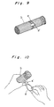
- In the process of manufacturing a wire harness of an automobile, the length of an electric cable is measured, the electric cable is cut, and a terminal is attached thereto. After all products manufactured in this process are inspected, cables are divided into a plurality of bundles each having a predetermined number of cables. Then, as shown in Fig. 9, bundles are bound at several portions in the vicinity of terminals of each bundle with a rubber band (a).
- Each bundle (b) is bound with the rubber band (a) as shown in Fig. 8. Conventionally, as shown in Fig. 10, the bundle (b) and a mushroom-shaped hook of the rubber band (a) are gripped with one hand and the rubber band (a) is wound around the bundle (b) with the other hand to lock the bundle (b) with the hook.
- However, this operation requires skillfulness and workmanship; much time and labor. Thus, sufficient operation efficiency cannot not obtained.
- Accordingly, an essential object of the present invention is to provide a binding apparatus not requiring workmanship.
- In accomplishing these and other objects, according to the present invention, there is provided a binding apparatus comprising: a frame; a pair of arms provided on the frame and vertically pivotal in opposite directions, wherein the moment at each pivotal axis thereof due to the dead weight thereof is greater in the outward direction than in the inward direction when the arms are the closed position; a gear mechanism for interlocking the arms with each other so that the arms are pivoted thereby in opposite directions at the same speed; hooks provided on an end of each of the arms between which a rubber band, having a mushroom-shaped hook attached thereto, shorter than a bundle of cables in the peripheral length thereof is spanned, wherein the interval between one of the hooks and the pivotal axis of one of the arms is longer than the interval between the other hook and the pivotal axis of the other arm; a cylinder, provided on one of the arms, in which when a rod moves forward, the arms pivot into the closed position thereof so that a portion of the rubber band hooked by one of the hooks is moved toward the other hook; maintaining means for keeping the open position of the arms; and releasing means for releasing the maintaining means.
- The binding apparatus further comprises: a stopper, vertically movable and serving as the maintaining means, inserted into an opening formed on a gear of the gear mechanism so as to keep the open position of the arms; a spring provided on the stopper so as to urge the stopper toward the gear; and an unlocking lever, provided in the center between the pivotal axes of each of the arms, which serves as the releasing means and moves downward from the gear against the urging force of the spring when the unlocking lever is pressed downward by the weight of the bundle of cables.
- In the above description, the length of the rubber band means a length when it is linear.
- According to the above construction, when the unlocking lever is pressed downward by the weight of a bundle of electric cables placed in the center of the rubber band spanned between both hooks provided on both arms kept in the open position, the stopper disengages from the gear. Thus, the arms are unlocked from the open position. If the unlocking lever is not provided, the arms are manually moved to take the closed position.
- Thereafter, the arms pivot into the closed position by the contraction force of the rubber band in the same speed because they are each connected with a gear rotating at the same speed. Thus, the rubber band is guided around the bundle of cables.
- Upon forward movement of the rod of the cylinder after both ends of the rubber band are located above the bundle of cables, one end of the rubber band hooked by the
hook 10a passes above its other end hooked by thehook 10b, namely, the upper surface of the hook in a mushroom configuration, thus being hooked by the hook. Then, the rod moves backward with the rubber band locked by the hook because the length of the rubber band is shorter than the circumference of the bundle of cables. - When the rubber band is removed from both hooks, the dead weight of the arms causes the arms to pivot into the open position. When the arms are in the initial condition, namely, the open position, the stoppers are inserted into the locking holes of the gear by the urging force of the spring when the bundle of cables is removed from the unlocking lever.
- These and other objects and the features of the present invention will become clear from the following description taken in conjunction with the preferred embodiments thereof with reference to the accompanying drawings, in which:
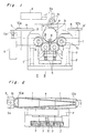
- Fig. 1 is a a front view showing a binding apparatus according to an embodiment of the present invention;
- Fig. 2 is a plan view showing the binding apparatus shown in Fig. 1;
- Fig. 3 is a view taken along the A-A line of Fig. 1;
- Fig. 4 is a view taken along the B-B line of Fig. 1;
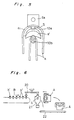
- Fig. 5 is a descriptive view showing the locking operation of a rubber ring;
- Figs. 6 and 7 are schematic views showing a use example of the embodiment;
- Fig. 8 is a front view showing a rubber ring; and
- Figs. 9 and 10 are descriptive views showing the operation for binding a bundle of electric cables.
- Before the description of the present invention proceeds, it is to be noted that like parts are designated by like reference numerals throughout the accompanying drawings.
- Referring now to the accompanied drawings, the embodiments of the present invention will be described below.
- As shown in Figs. 1 through 4, a frame (F) is provided with a pair of
arms axes Gears pivotal axes arms gears gears arms - Stoppers 4 and 4 positioned below the
gears springs arms gear 3 so as to keep thearms stoppers arms stoppers arms - An
unlocking lever 8 vertically extending beyond thegear 3 is provided in the center between the stoppers 4 and 4. Upon downward movement of thelever 8 from the position shown by a solid line of Fig. 1 to the position shown by a one-dot chain line of Fig. 1, the stoppers 4 and 4 move downward and unlocked from the locking holes 6 and 6. Thus, thearms -
Hooks arm 1, respectively. Thehook 10a is sectionally semicircular. The portion of thehook 10a in which thehook 10a is mounted on thearm 1 is solid, and the peripheral portion thereof is semicylindrical. Thehook 10b is sectionally elliptical and is cylindrical in the peripheral portion thereof. The distance between the hooked portion of the rubber band (a) hooked by thehook 10a and thepivotal axis 1a of onearm 1 is a little longer than the distance between the hooked portion of the rubber band (a) hooked by thehook 10b and thepivotal axis 1b of theother arm 1. Thus, when thearms arms 1 is provided with anair cylinder 9. Upon forward movement of therod 9a of theair cylinder 9 through the guide of a slit (S) of thehook 10a, thearms - When the
arms arms pivotal axes air cylinder 9 is each set to be greater in the outward direction than in the inward direction as shown by arrows of Fig. 1. Thus, when the rubber band (a) is removed from thehooks arms arms - The operation of the binding apparatus of the above-described construction is described below.
- As shown by a solid line of Fig. 1, when the
arms hooks - When a bundle (b) of electric cables is supplied downward to the center of the rubber band (a) as shown by a one-dot chain line with the
arms arms unlocking lever 8 is pressed downward by the weight of the cable bundle (b) through the rubber band (a) and as a result, the stoppers 4 and 4 move downward and unlocked from the locking holes 6 and 6 of thegears arms - Upon forward movement of the
rod 9a of theair cylinder 9 as shown by a one dot chain line of Fig. 1 after both end portions (hooked portions) of the rubber band (a) are located above the upper surface of the cable bundle (b), the end portion a₁ of the rubber band (a) passes above the upper surface of the other end portion thereof, namely, the upper surface of the hook (a′) as shown in Figs. 1 and 5. Consequently, the end portion a₁ of the rubber band (a) disengages from thehook 10a and is hooked by the hook (a′). Then, therod 9a moves backward with the rubber band (a) locking the cable bundle (b). The movement amount of therod 9a is set by an automatic control in consideration of the circumference of the cable bundle (b). - When the rubber band (a) spanned between both
hooks arms unlocking lever 8 in the initial condition of thearms gear 3 by thespring 5. - The binding apparatus (A) is used as shown in Figs. 6 and 7. That is, cables (b′) fed from a known conveyor belt (B) are stocked in a
cable holding hand 21 through acable hand 20. When a predetermined number of cables (b′) has been stocked in thecable holding hand 21, the cable bundle (b) is guided to the binding apparatus (A) by moving thecable holding hand 21 as shown in Fig. 7 or the binding apparatus (A) as shown in Fig. 6. Then, the cable bundle (b) is bound with a rubber band according to the operation described above. After the cable bundle (b) is bound, the bound bundle (b) is transported to the subsequent process by a belt conveyor. - The
arms gear 3 without thegear 2. In this case, the mounting direction and the length of thehooks arms lever 8 and both end portions (hooked portions) of the rubber band (a) are located above the cable bundle (b) when thearms rod 9a may serve as thehook 10a so that therod 9a serves as a means for hooking the rubber band (a). In this case, the hooking width (t) of therod 9a shown in Fig. 2 is smaller than the width (t′) of the hook (a′) so that the end portion a₁ (hooked portion) of the rubber band (a) passes above the hook (a′) by flexing the hook (a′). - The binding apparatus according to the present invention may be employed to bind other things, the configuration of which are an electric cable as well as the electric cable bundle (b).
- According to the above construction, the arms pivot into the closed position owing to the contraction force of a rubber band so as to wind the rubber band around a bundle of cables. After the bundle of cables is bound with the rubber band, the
arms - Although the present invention has been fully described in connection with the preferred embodiments thereof with reference to the accompanying drawings, it is to be noted that various changes and modifications are apparent to those skilled in the art. Such changes and modifications are to be understood as included within the scope of the present invention as defined by the appended claims unless they depart therefrom.
Claims (2)
- A binding apparatus comprising:
a frame (F);
a pair of arms (1,1) provided on said frame and vertically pivotal in opposite directions, wherein the moment at each pivotal axis thereof due to the dead weight thereof is greater in the outward direction than in the inward direction when said arms are in the closed position;
a gear mechanism (2,3) for interlocking said arms with each other so that said arms are pivoted thereby in opposite directions at the same speed;
hooks (10a,10b) provided on an end of each of said arms between which a rubber band (a), having a mushroom-shaped hook attached thereto and being shorter than a bundle of cables in the peripheral length thereof is spanned, wherein the interval between one of said hooks and the pivotal axis of one of said arms is longer than the interval between the other hook and the pivotal axis of the other arm;
a cylinder (9), provided on one of said arms, in which when its rod (9a) moves outward, said arms pivot into the closed position thereof so that a portion of said rubber band hooked by one of said hooks is moved toward the other hook;
maintaining means (4-8) for keeping the open position of said arms; and
releasing means for releasing said maintaining means. - A binding apparatus as defined in claim 1 comprising:
a stopper (4), vertically movable and serving as said maintaining means, inserted into an opening formed on a gear of said gear mechanism so as to keep the open position of said arms (1,1);
a spring (5) provided on said stopper so as to urge said stopper toward said gear (3); and
an unlocking lever (8), provided in the center between the pivotal axes of each of said arms, which serves as said releasing means and moves downward from said gear against the urging force of said spring when said unlocking lever is pressed downward by the weight of the bundle of cables (6).
Applications Claiming Priority (2)
| Application Number | Priority Date | Filing Date | Title |
|---|---|---|---|
| JP298361/90 | 1990-11-02 | ||
| JP2298361A JP2779263B2 (en) | 1990-11-02 | 1990-11-02 | Binding device |
Publications (2)
| Publication Number | Publication Date |
|---|---|
| EP0483684A1 EP0483684A1 (en) | 1992-05-06 |
| EP0483684B1 true EP0483684B1 (en) | 1994-07-27 |
Family
ID=17858695
Family Applications (1)
| Application Number | Title | Priority Date | Filing Date |
|---|---|---|---|
| EP91118239A Expired - Lifetime EP0483684B1 (en) | 1990-11-02 | 1991-10-25 | Apparatus for binding articles with a rubber band having a mushroom-shaped hook |
Country Status (4)
| Country | Link |
|---|---|
| US (1) | US5203260A (en) |
| EP (1) | EP0483684B1 (en) |
| JP (1) | JP2779263B2 (en) |
| DE (1) | DE69103122T2 (en) |
Families Citing this family (1)
| Publication number | Priority date | Publication date | Assignee | Title |
|---|---|---|---|---|
| JP2001287711A (en) | 2000-04-05 | 2001-10-16 | Sumitomo Wiring Syst Ltd | Apparatus and method for bunching electric wire |
Family Cites Families (10)
| Publication number | Priority date | Publication date | Assignee | Title |
|---|---|---|---|---|
| US2236936A (en) * | 1939-11-08 | 1941-04-01 | Walter W Camp | Device for applying rubber bands |
| US2376138A (en) * | 1944-04-25 | 1945-05-15 | Harrison Gale | Means for completing the packaging of berries or the like |
| US3288055A (en) * | 1963-07-18 | 1966-11-29 | Du Pont | Packaging apparatus |
| US3186333A (en) * | 1963-11-01 | 1965-06-01 | Kett Tool Co | Rubber band stretching apparatus |
| DE2620690C2 (en) * | 1976-05-11 | 1986-06-05 | Croon & Lucke Maschinenfabrik Gmbh + Co Kg, 7947 Mengen | Device for banding a ball |
| US4335490A (en) * | 1978-10-23 | 1982-06-22 | Teachout Donald O | Band and clip article |
| US4188871A (en) * | 1978-10-23 | 1980-02-19 | Teachout Donald O | Band and clip method |
| US4470241A (en) * | 1982-05-21 | 1984-09-11 | Salinas Valley Engineering & Manufacturing, Inc. | Apparatus for bunching, trimming, and banding vegetables |
| US4601155A (en) * | 1984-09-14 | 1986-07-22 | Robert Alameda | Elastic band application system |
| DE3619089A1 (en) * | 1986-06-06 | 1987-12-10 | Hermann Passing | Bundling harness for underground works articles |
-
1990
- 1990-11-02 JP JP2298361A patent/JP2779263B2/en not_active Expired - Fee Related
-
1991
- 1991-10-18 US US07/779,271 patent/US5203260A/en not_active Expired - Lifetime
- 1991-10-25 DE DE69103122T patent/DE69103122T2/en not_active Expired - Fee Related
- 1991-10-25 EP EP91118239A patent/EP0483684B1/en not_active Expired - Lifetime
Also Published As
| Publication number | Publication date |
|---|---|
| JP2779263B2 (en) | 1998-07-23 |
| DE69103122D1 (en) | 1994-09-01 |
| US5203260A (en) | 1993-04-20 |
| EP0483684A1 (en) | 1992-05-06 |
| JPH04173519A (en) | 1992-06-22 |
| DE69103122T2 (en) | 1994-11-03 |
Similar Documents
| Publication | Publication Date | Title |
|---|---|---|
| US4638558A (en) | Wire processing method and apparatus | |
| US4653185A (en) | Apparatus for mounting tension springs automatically | |
| US4916811A (en) | Process and apparatus for automatically attaching terminals to cable ends | |
| US4375229A (en) | Method and apparatus of automatically positioning wire ends for multi-mode end processing | |
| US5427327A (en) | Method and apparatus for capturing and positioning a cable | |
| RU2483405C2 (en) | Machine for production of cable bundles and method for production of cable bundles | |
| JPH0664949B2 (en) | Harness manufacturing equipment | |
| US5465478A (en) | Apparatus for manipulating wound cables | |
| US3042186A (en) | Conveying apparatus for individual objects | |
| EP0157654A1 (en) | Method and apparatus for automatically doffing and donning take up packages on a winder | |
| US5203260A (en) | Binding apparatus for binding a bundle of lables or the like | |
| JP2004256300A (en) | Method for mechanically winding a cable and apparatus therefor | |
| US3964142A (en) | Apparatus for cutting and stripping insulated wire | |
| US5740608A (en) | Method of making and stacking electrical leads | |
| EP0359297B1 (en) | Methods and apparatus for winding two-pole electric motor stators | |
| US4757606A (en) | Method and apparatus for terminal insertion | |
| US5305508A (en) | Cable-bundling equipment for cable-processing machines | |
| US4786454A (en) | Process for the production of flexible connectors | |
| US5522691A (en) | Apparatus for manipulating connectors | |
| EP0546512A1 (en) | Sheet gripper assembly | |
| US20240136090A1 (en) | Taping head | |
| EP0487012B1 (en) | Machine and process for coiling and winding tubular sleeves in elastomeric material incorporating reinforcing fibers | |
| DE4102599A1 (en) | METHOD AND DEVICE FOR REMOVING A TORSION SPRING | |
| US5370237A (en) | Method and apparatus for attaching connectors to a cable | |
| JPS6254687B2 (en) |
Legal Events
| Date | Code | Title | Description |
|---|---|---|---|
| PUAI | Public reference made under article 153(3) epc to a published international application that has entered the european phase |
Free format text: ORIGINAL CODE: 0009012 |
|
| AK | Designated contracting states |
Kind code of ref document: A1 Designated state(s): CH DE GB LI |
|
| 17P | Request for examination filed |
Effective date: 19920720 |
|
| 17Q | First examination report despatched |
Effective date: 19930916 |
|
| GRAA | (expected) grant |
Free format text: ORIGINAL CODE: 0009210 |
|
| AK | Designated contracting states |
Kind code of ref document: B1 Designated state(s): CH DE GB LI |
|
| REF | Corresponds to: |
Ref document number: 69103122 Country of ref document: DE Date of ref document: 19940901 |
|
| PLBE | No opposition filed within time limit |
Free format text: ORIGINAL CODE: 0009261 |
|
| STAA | Information on the status of an ep patent application or granted ep patent |
Free format text: STATUS: NO OPPOSITION FILED WITHIN TIME LIMIT |
|
| 26N | No opposition filed | ||
| PGFP | Annual fee paid to national office [announced via postgrant information from national office to epo] |
Ref country code: GB Payment date: 20011024 Year of fee payment: 11 |
|
| PGFP | Annual fee paid to national office [announced via postgrant information from national office to epo] |
Ref country code: DE Payment date: 20011112 Year of fee payment: 11 |
|
| PGFP | Annual fee paid to national office [announced via postgrant information from national office to epo] |
Ref country code: CH Payment date: 20011114 Year of fee payment: 11 |
|
| REG | Reference to a national code |
Ref country code: GB Ref legal event code: IF02 |
|
| PG25 | Lapsed in a contracting state [announced via postgrant information from national office to epo] |
Ref country code: GB Free format text: LAPSE BECAUSE OF NON-PAYMENT OF DUE FEES Effective date: 20021025 |
|
| PG25 | Lapsed in a contracting state [announced via postgrant information from national office to epo] |
Ref country code: LI Free format text: LAPSE BECAUSE OF NON-PAYMENT OF DUE FEES Effective date: 20021031 Ref country code: CH Free format text: LAPSE BECAUSE OF NON-PAYMENT OF DUE FEES Effective date: 20021031 |
|
| PG25 | Lapsed in a contracting state [announced via postgrant information from national office to epo] |
Ref country code: DE Free format text: LAPSE BECAUSE OF NON-PAYMENT OF DUE FEES Effective date: 20030501 |
|
| REG | Reference to a national code |
Ref country code: CH Ref legal event code: PL |
|
| GBPC | Gb: european patent ceased through non-payment of renewal fee |