EP0483477A1 - Flexible optical device for the transmission of light and use of the device - Google Patents
Flexible optical device for the transmission of light and use of the device Download PDFInfo
- Publication number
- EP0483477A1 EP0483477A1 EP91114441A EP91114441A EP0483477A1 EP 0483477 A1 EP0483477 A1 EP 0483477A1 EP 91114441 A EP91114441 A EP 91114441A EP 91114441 A EP91114441 A EP 91114441A EP 0483477 A1 EP0483477 A1 EP 0483477A1
- Authority
- EP
- European Patent Office
- Prior art keywords
- core
- component according
- area
- light
- coupling
- Prior art date
- Legal status (The legal status is an assumption and is not a legal conclusion. Google has not performed a legal analysis and makes no representation as to the accuracy of the status listed.)
- Granted
Links
- 230000003287 optical effect Effects 0.000 title claims abstract description 79
- 230000005540 biological transmission Effects 0.000 title claims abstract description 41
- 239000011521 glass Substances 0.000 claims abstract description 52
- VYPSYNLAJGMNEJ-UHFFFAOYSA-N silicon dioxide Inorganic materials O=[Si]=O VYPSYNLAJGMNEJ-UHFFFAOYSA-N 0.000 claims abstract description 34
- 238000005253 cladding Methods 0.000 claims abstract description 32
- 239000000463 material Substances 0.000 claims abstract description 30
- 230000005855 radiation Effects 0.000 claims abstract description 23
- UFHFLCQGNIYNRP-UHFFFAOYSA-N Hydrogen Chemical compound [H][H] UFHFLCQGNIYNRP-UHFFFAOYSA-N 0.000 claims abstract description 11
- 229910052739 hydrogen Inorganic materials 0.000 claims abstract description 11
- 239000001257 hydrogen Substances 0.000 claims abstract description 11
- YZCKVEUIGOORGS-OUBTZVSYSA-N Deuterium Chemical compound [2H] YZCKVEUIGOORGS-OUBTZVSYSA-N 0.000 claims abstract description 8
- 229910052805 deuterium Inorganic materials 0.000 claims abstract description 8
- 230000007423 decrease Effects 0.000 claims abstract description 6
- 230000008878 coupling Effects 0.000 claims description 46
- 238000010168 coupling process Methods 0.000 claims description 46
- 238000005859 coupling reaction Methods 0.000 claims description 46
- 239000010410 layer Substances 0.000 claims description 33
- 230000007704 transition Effects 0.000 claims description 17
- 230000007547 defect Effects 0.000 claims description 12
- YCKRFDGAMUMZLT-UHFFFAOYSA-N Fluorine atom Chemical compound [F] YCKRFDGAMUMZLT-UHFFFAOYSA-N 0.000 claims description 11
- 239000011737 fluorine Substances 0.000 claims description 11
- 229910052731 fluorine Inorganic materials 0.000 claims description 11
- 239000011241 protective layer Substances 0.000 claims description 11
- 239000004033 plastic Substances 0.000 claims description 9
- 238000009792 diffusion process Methods 0.000 claims description 8
- RTAQQCXQSZGOHL-UHFFFAOYSA-N Titanium Chemical compound [Ti] RTAQQCXQSZGOHL-UHFFFAOYSA-N 0.000 claims description 7
- 230000004888 barrier function Effects 0.000 claims description 7
- 238000009826 distribution Methods 0.000 claims description 7
- 238000005286 illumination Methods 0.000 claims description 7
- 239000010936 titanium Substances 0.000 claims description 7
- 229910052719 titanium Inorganic materials 0.000 claims description 7
- 229910052751 metal Inorganic materials 0.000 claims description 6
- 239000002184 metal Substances 0.000 claims description 6
- XLYOFNOQVPJJNP-UHFFFAOYSA-M hydroxide Chemical compound [OH-] XLYOFNOQVPJJNP-UHFFFAOYSA-M 0.000 claims description 5
- 239000001301 oxygen Substances 0.000 claims description 5
- 229910052760 oxygen Inorganic materials 0.000 claims description 5
- OKTJSMMVPCPJKN-UHFFFAOYSA-N Carbon Chemical compound [C] OKTJSMMVPCPJKN-UHFFFAOYSA-N 0.000 claims description 4
- 229910052799 carbon Inorganic materials 0.000 claims description 3
- ZOXJGFHDIHLPTG-UHFFFAOYSA-N Boron Chemical compound [B] ZOXJGFHDIHLPTG-UHFFFAOYSA-N 0.000 claims description 2
- 229910052796 boron Inorganic materials 0.000 claims description 2
- 230000006378 damage Effects 0.000 abstract description 27
- 230000005284 excitation Effects 0.000 abstract description 5
- -1 hydroxyl ions Chemical class 0.000 abstract description 5
- 239000010453 quartz Substances 0.000 abstract description 2
- 230000035882 stress Effects 0.000 description 17
- 230000015572 biosynthetic process Effects 0.000 description 6
- 230000003667 anti-reflective effect Effects 0.000 description 5
- 238000013461 design Methods 0.000 description 4
- 238000004519 manufacturing process Methods 0.000 description 4
- 238000000034 method Methods 0.000 description 4
- 238000005520 cutting process Methods 0.000 description 3
- 238000006073 displacement reaction Methods 0.000 description 3
- IJGRMHOSHXDMSA-UHFFFAOYSA-N Atomic nitrogen Chemical compound N#N IJGRMHOSHXDMSA-UHFFFAOYSA-N 0.000 description 2
- 238000010521 absorption reaction Methods 0.000 description 2
- 238000013459 approach Methods 0.000 description 2
- 230000008901 benefit Effects 0.000 description 2
- 238000000151 deposition Methods 0.000 description 2
- 230000008021 deposition Effects 0.000 description 2
- PCHJSUWPFVWCPO-UHFFFAOYSA-N gold Chemical compound [Au] PCHJSUWPFVWCPO-UHFFFAOYSA-N 0.000 description 2
- 239000010931 gold Substances 0.000 description 2
- 229910052737 gold Inorganic materials 0.000 description 2
- 230000009442 healing mechanism Effects 0.000 description 2
- 238000005259 measurement Methods 0.000 description 2
- 230000035515 penetration Effects 0.000 description 2
- 230000009467 reduction Effects 0.000 description 2
- 239000011343 solid material Substances 0.000 description 2
- 239000000758 substrate Substances 0.000 description 2
- HGCGQDMQKGRJNO-UHFFFAOYSA-N xenon monochloride Chemical compound [Xe]Cl HGCGQDMQKGRJNO-UHFFFAOYSA-N 0.000 description 2
- GYHNNYVSQQEPJS-UHFFFAOYSA-N Gallium Chemical compound [Ga] GYHNNYVSQQEPJS-UHFFFAOYSA-N 0.000 description 1
- ZOKXTWBITQBERF-UHFFFAOYSA-N Molybdenum Chemical compound [Mo] ZOKXTWBITQBERF-UHFFFAOYSA-N 0.000 description 1
- OAICVXFJPJFONN-UHFFFAOYSA-N Phosphorus Chemical compound [P] OAICVXFJPJFONN-UHFFFAOYSA-N 0.000 description 1
- 238000001069 Raman spectroscopy Methods 0.000 description 1
- 230000006978 adaptation Effects 0.000 description 1
- 230000003679 aging effect Effects 0.000 description 1
- 229910052782 aluminium Inorganic materials 0.000 description 1
- XAGFODPZIPBFFR-UHFFFAOYSA-N aluminium Chemical compound [Al] XAGFODPZIPBFFR-UHFFFAOYSA-N 0.000 description 1
- 238000002399 angioplasty Methods 0.000 description 1
- QVGXLLKOCUKJST-UHFFFAOYSA-N atomic oxygen Chemical compound [O] QVGXLLKOCUKJST-UHFFFAOYSA-N 0.000 description 1
- 238000006243 chemical reaction Methods 0.000 description 1
- 239000004020 conductor Substances 0.000 description 1
- 238000001816 cooling Methods 0.000 description 1
- 230000001419 dependent effect Effects 0.000 description 1
- 238000001514 detection method Methods 0.000 description 1
- 230000000694 effects Effects 0.000 description 1
- 239000000835 fiber Substances 0.000 description 1
- 229920002313 fluoropolymer Polymers 0.000 description 1
- 239000004811 fluoropolymer Substances 0.000 description 1
- 229910052733 gallium Inorganic materials 0.000 description 1
- 229910052732 germanium Inorganic materials 0.000 description 1
- GNPVGFCGXDBREM-UHFFFAOYSA-N germanium atom Chemical compound [Ge] GNPVGFCGXDBREM-UHFFFAOYSA-N 0.000 description 1
- 239000003365 glass fiber Substances 0.000 description 1
- 229910002804 graphite Inorganic materials 0.000 description 1
- 239000010439 graphite Substances 0.000 description 1
- 125000002887 hydroxy group Chemical group [H]O* 0.000 description 1
- 239000011261 inert gas Substances 0.000 description 1
- 150000002500 ions Chemical class 0.000 description 1
- 238000001182 laser chemical vapour deposition Methods 0.000 description 1
- 230000007774 longterm Effects 0.000 description 1
- 238000012423 maintenance Methods 0.000 description 1
- 150000002739 metals Chemical class 0.000 description 1
- 229910052750 molybdenum Inorganic materials 0.000 description 1
- 239000011733 molybdenum Substances 0.000 description 1
- 229910052757 nitrogen Inorganic materials 0.000 description 1
- 238000012634 optical imaging Methods 0.000 description 1
- 239000002245 particle Substances 0.000 description 1
- 229910052698 phosphorus Inorganic materials 0.000 description 1
- 239000011574 phosphorus Substances 0.000 description 1
- 238000004321 preservation Methods 0.000 description 1
- 238000012545 processing Methods 0.000 description 1
- 230000008929 regeneration Effects 0.000 description 1
- 238000011069 regeneration method Methods 0.000 description 1
- 230000000717 retained effect Effects 0.000 description 1
- 238000004611 spectroscopical analysis Methods 0.000 description 1
- 238000001228 spectrum Methods 0.000 description 1
- 239000000126 substance Substances 0.000 description 1
- 238000001356 surgical procedure Methods 0.000 description 1
- 238000005496 tempering Methods 0.000 description 1
- 238000011144 upstream manufacturing Methods 0.000 description 1
- 238000003466 welding Methods 0.000 description 1
Images


Classifications
-
- G—PHYSICS
- G02—OPTICS
- G02B—OPTICAL ELEMENTS, SYSTEMS OR APPARATUS
- G02B6/00—Light guides; Structural details of arrangements comprising light guides and other optical elements, e.g. couplings
- G02B6/24—Coupling light guides
- G02B6/42—Coupling light guides with opto-electronic elements
- G02B6/4201—Packages, e.g. shape, construction, internal or external details
- G02B6/4202—Packages, e.g. shape, construction, internal or external details for coupling an active element with fibres without intermediate optical elements, e.g. fibres with plane ends, fibres with shaped ends, bundles
- G02B6/4203—Optical features
-
- C—CHEMISTRY; METALLURGY
- C03—GLASS; MINERAL OR SLAG WOOL
- C03C—CHEMICAL COMPOSITION OF GLASSES, GLAZES OR VITREOUS ENAMELS; SURFACE TREATMENT OF GLASS; SURFACE TREATMENT OF FIBRES OR FILAMENTS MADE FROM GLASS, MINERALS OR SLAGS; JOINING GLASS TO GLASS OR OTHER MATERIALS
- C03C3/00—Glass compositions
- C03C3/04—Glass compositions containing silica
- C03C3/06—Glass compositions containing silica with more than 90% silica by weight, e.g. quartz
-
- C—CHEMISTRY; METALLURGY
- C23—COATING METALLIC MATERIAL; COATING MATERIAL WITH METALLIC MATERIAL; CHEMICAL SURFACE TREATMENT; DIFFUSION TREATMENT OF METALLIC MATERIAL; COATING BY VACUUM EVAPORATION, BY SPUTTERING, BY ION IMPLANTATION OR BY CHEMICAL VAPOUR DEPOSITION, IN GENERAL; INHIBITING CORROSION OF METALLIC MATERIAL OR INCRUSTATION IN GENERAL
- C23C—COATING METALLIC MATERIAL; COATING MATERIAL WITH METALLIC MATERIAL; SURFACE TREATMENT OF METALLIC MATERIAL BY DIFFUSION INTO THE SURFACE, BY CHEMICAL CONVERSION OR SUBSTITUTION; COATING BY VACUUM EVAPORATION, BY SPUTTERING, BY ION IMPLANTATION OR BY CHEMICAL VAPOUR DEPOSITION, IN GENERAL
- C23C16/00—Chemical coating by decomposition of gaseous compounds, without leaving reaction products of surface material in the coating, i.e. chemical vapour deposition [CVD] processes
- C23C16/44—Chemical coating by decomposition of gaseous compounds, without leaving reaction products of surface material in the coating, i.e. chemical vapour deposition [CVD] processes characterised by the method of coating
- C23C16/48—Chemical coating by decomposition of gaseous compounds, without leaving reaction products of surface material in the coating, i.e. chemical vapour deposition [CVD] processes characterised by the method of coating by irradiation, e.g. photolysis, radiolysis, particle radiation
- C23C16/483—Chemical coating by decomposition of gaseous compounds, without leaving reaction products of surface material in the coating, i.e. chemical vapour deposition [CVD] processes characterised by the method of coating by irradiation, e.g. photolysis, radiolysis, particle radiation using coherent light, UV to IR, e.g. lasers
-
- G—PHYSICS
- G02—OPTICS
- G02B—OPTICAL ELEMENTS, SYSTEMS OR APPARATUS
- G02B6/00—Light guides; Structural details of arrangements comprising light guides and other optical elements, e.g. couplings
- G02B6/10—Light guides; Structural details of arrangements comprising light guides and other optical elements, e.g. couplings of the optical waveguide type
- G02B6/102—Light guides; Structural details of arrangements comprising light guides and other optical elements, e.g. couplings of the optical waveguide type for infrared and ultraviolet radiation
-
- G—PHYSICS
- G02—OPTICS
- G02B—OPTICAL ELEMENTS, SYSTEMS OR APPARATUS
- G02B6/00—Light guides; Structural details of arrangements comprising light guides and other optical elements, e.g. couplings
- G02B6/24—Coupling light guides
- G02B6/26—Optical coupling means
- G02B6/262—Optical details of coupling light into, or out of, or between fibre ends, e.g. special fibre end shapes or associated optical elements
-
- G—PHYSICS
- G02—OPTICS
- G02B—OPTICAL ELEMENTS, SYSTEMS OR APPARATUS
- G02B6/00—Light guides; Structural details of arrangements comprising light guides and other optical elements, e.g. couplings
- G02B6/24—Coupling light guides
- G02B6/42—Coupling light guides with opto-electronic elements
- G02B6/4296—Coupling light guides with opto-electronic elements coupling with sources of high radiant energy, e.g. high power lasers, high temperature light sources
-
- C—CHEMISTRY; METALLURGY
- C03—GLASS; MINERAL OR SLAG WOOL
- C03C—CHEMICAL COMPOSITION OF GLASSES, GLAZES OR VITREOUS ENAMELS; SURFACE TREATMENT OF GLASS; SURFACE TREATMENT OF FIBRES OR FILAMENTS MADE FROM GLASS, MINERALS OR SLAGS; JOINING GLASS TO GLASS OR OTHER MATERIALS
- C03C2201/00—Glass compositions
- C03C2201/06—Doped silica-based glasses
- C03C2201/08—Doped silica-based glasses containing boron or halide
- C03C2201/12—Doped silica-based glasses containing boron or halide containing fluorine
-
- C—CHEMISTRY; METALLURGY
- C03—GLASS; MINERAL OR SLAG WOOL
- C03C—CHEMICAL COMPOSITION OF GLASSES, GLAZES OR VITREOUS ENAMELS; SURFACE TREATMENT OF GLASS; SURFACE TREATMENT OF FIBRES OR FILAMENTS MADE FROM GLASS, MINERALS OR SLAGS; JOINING GLASS TO GLASS OR OTHER MATERIALS
- C03C2201/00—Glass compositions
- C03C2201/06—Doped silica-based glasses
- C03C2201/20—Doped silica-based glasses containing non-metals other than boron or halide
- C03C2201/21—Doped silica-based glasses containing non-metals other than boron or halide containing molecular hydrogen
-
- C—CHEMISTRY; METALLURGY
- C03—GLASS; MINERAL OR SLAG WOOL
- C03C—CHEMICAL COMPOSITION OF GLASSES, GLAZES OR VITREOUS ENAMELS; SURFACE TREATMENT OF GLASS; SURFACE TREATMENT OF FIBRES OR FILAMENTS MADE FROM GLASS, MINERALS OR SLAGS; JOINING GLASS TO GLASS OR OTHER MATERIALS
- C03C2201/00—Glass compositions
- C03C2201/06—Doped silica-based glasses
- C03C2201/20—Doped silica-based glasses containing non-metals other than boron or halide
- C03C2201/23—Doped silica-based glasses containing non-metals other than boron or halide containing hydroxyl groups
Definitions
- the invention relates to a flexible, optical component with a core and a sheath enveloping it, having a lower refractive index than the core, which essentially consist of quartz glass, for the transmission of ultraviolet light with high power densities, which is to be transmitted in the direction of radiation of the ultraviolet Seen in front of at least one flexible, cylindrical region, the light has a tapering region, the cross-sectional area of which decreases steadily in the direction of irradiation and which has a coupling-in surface on the end facing a light source emitting ultraviolet radiation and a coupling-out surface on the end facing away from the light source.
- the optical power and energy densities that can be transmitted by means of optical components are limited by material-specific destruction thresholds above which the optical properties of the transmission media are irreversibly changed.
- the destruction threshold for the coupling surface into which the light to be transmitted is coupled is lower than for the solid material of the component in which the light to be transmitted is guided.
- U.S. Patent 4,641,912. describes an optical transmission path for the transmission of pulsed excimer laser light, which has a wavelength in the range between 40 to 400 nano-meters, for use in angioplasty surgery.
- the optical component used to transmit the laser light is designed as a flexible optical waveguide with a core made of pure quartz glass and a cladding made of doped quartz glass, the refractive index profile of which has a step profile and the coupling side of which is expanded in a funnel shape towards the laser.
- the design as a flexible optical waveguide allows variable light guidance and the funnel-shaped extension of the coupling side enables a widening of the light spot compared to a direct coupling into the fiber end face and thus a reduction in the energy density on the coupling surface with the same laser output energy. Due to total reflections at the core / cladding interface, the injected laser light is transferred to the smaller cross-section of the optical waveguide and the optical power density to be absorbed by the quartz glass is gradually increased in the area after the coupling-in area. The power density reaches its maximum only on the end face of the cylindrical region of the optical waveguide. This has the advantage that laser light with a higher optical power density than the destruction threshold of the coupling surface allows can be transmitted.
- the present invention has for its object to provide a flexible, optical component for the transmission of ultraviolet light and the use of the component, which has improved material properties with respect to the destruction thresholds and its geometric design with regard to the excitation conditions for the light to be transmitted and the maintenance of mechanical and optical properties is optimized in practical use.
- the core glass has a hydroxyl ion content in the range from 50 ppm to 1200 ppm and an oxygen ion defect concentration of less than 1017 per gram of glass and the cladding glass has a hydroxyl ion content in the
- the range from 50 ppm to 250 ppm shows that the hydrogen and / or deuterium concentration in the core glass and in the cladding glass is in a range from a total of 5x10¹⁶ molecules per cubic centimeter to 5x10²¹ molecules per cubic centimeter, that the length ( L) of the tapered area has a value between 15 to 150 times the core diameter (Dk) of the cylindrical area and that the ratio of the coupling-in area and the core cross-sectional area of the cylindrical area has a value between 2 and 100.
- excess or insufficient oxygen ion content leads to atomic defects which impair the optical transmission properties of the quartz glass.
- a hydrogen and / or deuterium loading of the quartz glass between 5x10¹⁶ molecules per cubic centimeter and 5x10²¹ molecules per cubic centimeter causes an atomic material defect to heal, for example by reaction of the hydrogen or deuterium with defects present or caused by the light to be transmitted, for example with oxygen gaps. This healing mechanism is also effective during the intended use of the optical part.
- the coupling-in area is the usable area for coupling in the light, namely the area of the core glass on the end of the optical component facing the light source and the area of the core glass on the base of the cylindrical area under the core cross-sectional area Area of the component, understood.
- the length of the tapered area suitable for coupling the optical power into the component depends on the diameter of the core in the cylindrical area. Satisfactory excitation conditions while largely maintaining the flexibility of the cylindrical area for the component are given, in particular, with a length of the tapered area between 15 times to 150 times the core diameter.
- the length of the tapered area is between 50 times to 100 times the core diameter in the cylindrical area and if the diameter ratio of the coupling area to the core cross-sectional area of the cylindrical area is between 10 and 50 owns.
- Doping of the core glass with fluorine with a proportion of less than 0.5% by weight has proven particularly useful, with the proviso that with only fluorine doping, the fluorine content in the core glass is such that the necessary refractive index difference between core glass and cladding glass is retained. Fluorine doping of less than 0.5 percent by weight can reduce the formation of defects in the quartz glass. With regard to good light guidance with sufficient mechanical stability and flexibility of the optical components, values between 1.02 and 2 and in particular between 1.02 and 1.1 have proven useful for the ratio of the shell diameter to the core diameter in the cylindrical region of the component.
- Doping core and / or cladding glass in such a way that the refractive indices in the area of the core / cladding interface gradually approach one another has proven to be particularly advantageous compared to a stepped refractive index profile.
- the stresses caused by mismatching of the thermal properties, in particular the expansion coefficients and the viscosities of the two glasses, which can lead to a lowering of the destruction thresholds and to an increase in the defect formation rate in the quartz glass, are thereby significantly reduced.
- the formation of the coupling-out surface with anti-reflective layers is particularly advantageous with regard to a reduction in the coupling-out losses that occur when the transmitted light is coupled out.
- Diameters of the decoupling surfaces between 2 and 50 times the core diameter of the cylindrical region have proven particularly useful.
- the radiation angle (divergence) when coupling out the transmitted light is significantly reduced in comparison to the numerical aperture of the component.
- the coupling surface is advantageously designed such that the focus diameter produced by the curvature is at most as large as the core diameter in the cylindrical region and the focus is in front of the beginning of the cylindrical region.
- Any radiation characteristics can be generated by a curved design of the coupling surface of the component.
- a filter element between the light source and the tapered area, the length of which is at least 10 mm and the diameter of which is at least as large as the largest diameter of the tapered area.
- This has proven particularly useful for broadband light transmissions, such as may be required in spectroscopy.
- Short-wave, ultraviolet light radiation that may occur has only a small penetration depth in quartz glass, but can cause severe material damage.
- the material damage caused by the light radiation is concentrated in the coupling-in area of the filter element by the addition of a filter element. It has proven that To connect the filter element detachably to the tapered area. This enables replacement or regeneration of the filter element.
- a filter element in front of the tapered area protects the tapered area from radiation damage and, by varying the optical properties of the filter element, enables the light beam guidance to be adapted to the coupling surface of the component.
- a filter element which contains titanium-doped quartz glass has proven to be advantageous. Doping with titanium shifts the absorption edge for the ultraviolet light radiation to longer wavelengths.
- the component has a diffusion barrier layer enveloping the core and the cladding. Due to the high diffusivity of hydrogen or deuterium in quartz glass, the hydrogen or deuterium concentration in a quartz glass loaded with it and the effect of the healing mechanism of these molecules on defects in the glass decrease over time. In order to avoid undesired diffusion out of the component, barrier layers which contain carbon or metal are particularly suitable.
- An outer protective layer made of plastic enveloping the core and the cladding offers protection for the optical component against mechanical damage.
- a protective layer consisting essentially of a plastic whose refractive index is smaller than that of the cladding glass is particularly suitable. The emergence of laterally scattered, high-energy light rays from the cladding glass, which would destroy the plastic of the protective layer and thus reduce the mechanical strength of the component, is reduced due to total reflection at the interface between the cladding glass and the protective layer.
- the protective layer on a radiation shielding layer made of plastic, the refractive index of which is smaller than the refractive index of the glass and which has an increased resistance to ultraviolet rays, or on the outer surface of a metal layer, which envelops the core and the cladding and which reflects the light on its inner surface.
- the metal layer can also serve as a diffusion barrier for out-diffusing particles.
- the component has a compressive stress layer which envelops the core and the cladding and which is made of quartz glass with a titanium content in the range of at least 4 percent by weight and at most 15 percent by weight consists.
- the strength-increasing compressive stresses induced by the titanium content in the compressive stress layer prevent the formation of surface cracks and increase the mechanical strength of the component.
- An embodiment of the optical component according to the invention which has a transition area on its side facing away from the light source, the core cross-sectional area of which continuously increases in the direction of the ultraviolet light radiation carried in the component, between the transition area and one to be treated by means of the ultraviolet light to be transmitted Material is arranged a transmission element, which consists essentially of quartz glass and whose smallest cross-sectional area is at least as large as the largest cross-sectional area of the transition area, especially when transmitting ultraviolet, high-energy light in, the component chemically, physically and / or thermally stressful environments , especially proven when transmitting ultraviolet, high-energy light in areas of elevated temperature.
- the cross-sectional area of the transmission element is to be understood as the cross-sectional area running parallel to the coupling-out area of the optical component.
- the design of the component with a transmission element that has a larger cross-sectional area than that in the cylindrical region of the component ensures longer service life of the component in a chemically, physically and / or thermally stressing environment, whereas the thinner cross-section of the cylindrical region ensures the flexibility of the component Component and the lighting. It turned out to be cheap To connect the transition region of the component and the transmission element to one another, in particular to fuse them together. This simplifies the handling of the component and simplifies its manufacture.
- the component according to the invention has proven itself for use as a beam converter for material treatment. It combines the ability to transmit the very high energy outputs required for material treatment with the greatest possible flexibility in lighting control.
- the beam quality of the light source expressed by the product of the beam diameter and the associated beam divergence
- high transmission values of over 90% can be achieved with a homogeneous power density on the coupling-out surface of the component. This is achieved by centric coupling, ie the light beam axis and the axis of the cylindrical area are the same.
- the focus diameter is only slightly smaller than the core diameter of the cylindrical region and the beam divergence is smaller than or equal to the acceptance angle of the cylindrical region, which is equal to the numerical aperture for a given refractive index difference between the core and the cladding.
- a parallel light beam is coupled into an illumination area of the coupling-in surface, the projection surface of which on a plane that is perpendicular to the lateral surface of the cylindrical section, the projection surface of the base area of the cylindrical section on this plane intersects at most 50% or a focused light bundle is coupled into the coupling surface in such a way that the axis of the cylindrical region which is extended up to the coupling surface does not intersect the focus surface.
- the focus area denotes the extent of the focus of the injected radiation transverse to the direction of radiation.
- the ring-shaped intensity profiles of the transmitted ultraviolet light generated in this way have very high power densities on the decoupling surface, which can hardly be achieved with other excitation methods. These ring-shaped intensity profiles are used in particular for cutting and separating solid materials. With a transverse displacement of the ring-shaped light intensity profile over the material surface to be cut with a constant displacement speed, the material entering the area of the intensity profile is exposed to approximately the same power densities with approximately the same dwell times. As a result, very sharp-edged cut edges are produced when the optical component is used as a beam converter.
- the component according to the invention provided with a transition region is also particularly suitable for use as an optical transmission path for high light outputs from a low temperature range to a high temperature range up to 1000 ° C. for material treatment, at least the cylindrical region and the transition region of the optical component being arranged in the low temperature range and the cylindrical area has a diameter of at most 1500 micrometers and an optical transmission element made of quartz glass, the smallest cross-sectional area of which is at least as large as the largest cross-sectional area of the transition area and which is arranged between the transition area and the material to be treated, projects into the high-temperature area .
- This optical transmission link is used in particular for the treatment of materials that are located in hot media.
- the optical transmission link combines the advantage of flexible light guidance with the possibility of being able to transmit high light outputs in a temperature range that is above the maximum operating temperature of flexible glass components.
- the transmission path also enables the transmission of light output from the material to be treated from the high-temperature range to the low-temperature range.
- combining several optical components into a bundle has proven itself, in which the longitudinal axes of the components run parallel to one another and their end faces end on both sides in common component end faces. This does while largely maintaining the flexibility of the individual optical component for the entire bundle, light outputs are available in the high-temperature range, the transmission of which would destroy a single optical component.
- reference number 1 denotes an optical component according to the invention, which comprises an elongated cylindrical region 2 and a tapering region 3.
- the tapering region 3 is seen in the direction of the irradiation of the ultraviolet light to be transmitted, which is indicated by the directional arrows 4, upstream of the cylindrical region 2 and fused with it.
- the cross-sectional area of the tapering area 3 is circular and decreases continuously in the direction of irradiation 4.
- the length L of the tapered area 3 is 20 mm.
- the component 1 has a core 5 with a likewise circular cross section and a diameter Dk of 600 micrometers in the cylindrical region 2 and a jacket 6 enveloping the core 5.
- the core 5 consists of high-purity synthetic quartz glass with a hydroxyl content of 650 ppm and a concentration of hydrogen of 1019 molecules per cubic centimeter.
- the defect concentration of oxygen ions measured by the Shelby method is below 1017 per cubic centimeter of core glass 5.
- the jacket 6 consists of high-purity, synthetic quartz glass which is doped with 4% by weight of fluorine and has a hydroxyl ion content of about 100 ppm . Due to its fluorine doping, the cladding glass 6 has a refractive index that is 16x10 ⁇ 3 lower than that of the core glass 5.
- the refractive indices of core and cladding glass 5.6 approach each other linearly in an intermediate region not shown in the drawing, so that the cross section through the layers of core and cladding glass 5.6 has a mesa-shaped refractive index profile.
- the differences in the viscosities and in the expansion coefficients caused by the different doping of the two quartz glasses and the resulting permanent stresses between core and cladding glass 5,6 resulting from the manufacturing process of component 1 are reduced by this refractive index profile.
- An increased defect formation rate due to stresses in the glasses 5, 6 during the practical use of the component 1 and a lowering of the destruction thresholds for the material damage caused by the ultraviolet light rays are thereby largely avoided.
- the thickness of the jacket 6 of 30 micrometers ensures adequate guidance of the light modes coupled into the core 5.
- the jacket diameter, which is marked with Dm, is thus 660 micrometers.
- the ratio of sheath to core diameter Dm, Dk is over the total component length 1 constant and is 1.1.
- the thicknesses of the layers that make up component 1 are designed to be as thin as possible, but so thick that they can perform their function to a sufficient extent, the diameters and thicknesses given below relating to the cylindrical area 2 of component 1, as shown in cross section in FIG. 1b.
- the compressive stress layer 7 enveloping the cladding glass 6 likewise consists of synthetic quartz glass, but which has a titanium content of 8 percent by weight.
- the compressive stress layer 7 is the outermost glass layer of the component 1.
- the titanium content lowers the coefficient of expansion of the quartz glass, so that compressive stresses are induced in the compressive stress layer 7 during the manufacturing process of the component 1, which prevent the formation of cracks from the surface of the compressive stress layer 7 and thereby increasing the overall mechanical stability of component 1.
- the thickness of the compressive stress layer 7 is 3 micrometers.
- a reflective gold layer 8 with a thickness of 0.1 micrometers is applied to the compressive stress layer 7.
- High-energy scattered light which occurs, for example, in the case of a non-optimized adaptation between component geometry 1 and the light beam to be transmitted in the coupling-in area of component 1 or due to scattering centers in the area of guided light modes, would become the plastic of protective layer 9, which is intended to protect component 1 from mechanical damage , to destroy.
- the reflective gold layer 8 prevents scattered light from escaping laterally from the jacket 6 or from the compressive stress layer 7 into the protective layer 9 and thus maintains the mechanical stability of the optical component 1. Since hydrogen and deuterium are able to use the component for To partially neutralize the transmission of high-energy, ultraviolet light rays arising material defects, it is necessary for long-term applications of component 1 to inhibit the diffusion of hydrogen out of the quartz glass from core 5 and jacket 6.
- a diffusion barrier layer 10 which is applied with a thickness of 0.2 micrometers and which consists of graphite. At the same time, the diffusion barrier layer 10 also prevents undesirable atoms or molecules from diffusing into the glass layers 5, 6, 7 of the component 1.
- the plastic of the protective layer 9 consists of a fluoropolymer and is of a thickness plotted by 40 micro meters. With centric and focused coupling of excimer laser light, a homogeneous power distribution results on the decoupling surface. Transmissions of greater than 90% for 20 mJ pulses with a pulse length of 20 ns are achieved by coupling in a focused laser beam with a focal spot diameter of 550 micrometers and a divergence smaller than the numerical aperture of component 1. The power densities achieved in the cylindrical region 2 are in the order of magnitude of the wavelength-dependent destruction threshold of the core glass 5.
- a light radiation which has only small penetration depths in quartz glass but can cause very severe material damage, is coupled into a cylindrical filter element 11 in the direction of irradiation 4.
- the filter element 11 has a core glass region 31 with a cross-sectional area that is somewhat smaller than the coupling surface 15 of the component 1 and a cladding glass region 32 that envelops the core glass region 31. It has a diameter of 3 mm and a length of 10 mm.
- the optical component 1 arranged after the filter element 11 has a tapering region 3 with a circular cross section and with a continuously tapering diameter, a cylindrical region 2 and a transition region 12 with a conically widening diameter, viewed in the direction of irradiation 4. Codotation of 3 ppm titanium to the quartz glass of the filter element 11 shifts the absorption edge of the quartz glass to a higher wavelength for the ultraviolet light coupled into the filter element 11. As a result, the tapered region 3 of the optical component 1 is protected from the short-wave, particularly high-energy components of the incident ultraviolet light. Material damage occurring during the broadband light transmission by means of the arrangement of component 1 and filter element 11 shown in FIG.
- the filter element 11 is concentrated in the coupling-in area 13 of the filter element 11, which is regenerated by tempering in a hydrogen-containing atmosphere and used again or possibly replaced by a new filter element 11.
- the light rays leaving the filter element 11 strike the coupling surface in an illumination area 15 of component 1, the coupling surface 15 being identical to the core cross-sectional area on the front side of the component 1 facing the light source and being larger by a factor of 3 than the cross-sectional area of the core 5 in the cylindrical region 2 of the component 1 and the illumination region being that Encloses the center of the coupling surface 15 and occupies approximately 90 percent of the coupling surface 15.
- the decoupling surface 16 Due to total reflection in the area of the interface between the core 5 and the jacket 3, the light coupled into the coupling surface 15 is transferred into the cylindrical core 5, in the initial area of which the light has its highest surface power density. Because of the conically widening transition region 12 and the widening of the guided light beam caused thereby, the decoupling surface 16 is also only exposed to an optical power density that is reduced compared to the power density in the cylindrical region 2.
- the coupling-out surface 16 is designed as a convexly curved surface with a dielectric anti-reflective layer 17.
- the decoupling surface 16 allows a focused decoupling of the transmitted light beam, while the anti-reflective layer 17 reduces the reflection losses during the decoupling of light and thus contributes to a high efficiency for the light transmission.
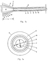
- a light beam emanating from a xenon chloride laser 18 (wavelength 308 nm, pulse length 100 ns, energy per pulse 6 mJ, laser beam diameter limited by apertures 19 of 0.6 mm in the direction of the directional arrows 4 into an illumination area 14 of the coupling-in area 15 with a surface power density of 20 MW / cm2, the power density in the cylindrical area 2 or at the coupling-out area 16 being an order of magnitude higher Illumination area 14 on a plane 20, which runs perpendicular to the lateral surface 21 of the cylindrical region 2, does not intersect with the projection of the end face 22 of the cylindrical region 2 onto the plane 20. Because of this coupling into the optical component 1 according to the invention, the coupling-out surface 16 generates an annular light intensity profile 23 that dur ch a not shown in the figure optical imaging system can be enlarged and made visible on a projection screen 24.
- the use of the component 1 as a beam converter for focused coupling of a laser beam is explained in more detail with the aid of the plan view, not to scale, of the coupling surface 15 of the optical component 1, parts designated by reference numbers that are not shown in FIG. 4 are explained, correspond to the parts designated by the same reference numerals in FIG. DM is the diameter of the end face of the tapering region 3 facing the laser, which is 2200 micrometers. DK identifies the diameter of the coupling surface 15 of the optical component 1.
- the coupling surface 15 corresponds to the surface portion of the core glass 5 on the entire end face of the tapering region 3 facing the laser.
- the exemplary embodiment is a surface with a circular cross section with a diameter of 2000 micro -Meter trained.
- the diameter of the jacket 6 in the cylindrical region 2 is 220 micrometers and is Dm, that of the core 5 is 200 micrometers and is designated Dk.
- the ratio of the coupling surface 15 to the core cross-sectional area of the cylindrical region 2 is thus 100: 1.
- a laser beam is focused in an illumination area 14 of the coupling-in area 15 of the optical component 1, the focus of which, viewed in the direction of irradiation 4, lies directly in front of the end face of the cylindrical area 2 and which occupies a focus area 25 which is circular in cross section and has a diameter of 180 micrometers, wherein the focus surface 25 is such that it has no point of intersection with the axis 26 of the cylindrical region 2 which is extended counter to the direction of radiation 4 of the laser beam up to the coupling surface 15.
- the distance from the center of the focus surface 25 from the axis 26 of the cylindrical region 2, which axis is extended to the coupling surface 15, is 250 micrometers.
- annular intensity profiles 23 of the light leaving the coupling-out surface 16 are generated, as are shown as a measurement result with an enlarged measuring rod in FIG. 5.
- the horizontal ones labeled X and Y, respectively Axes indicate the lateral extent of the measured light intensity profile 23 in millimeters, the vertical axis designated Z denotes the measured light intensity in relative units.
- the intensity profile generated has approximately the same light intensities with power densities up to in a well-defined ring region 27 with a ring width of approximately 0.06 mm 100 MW per cm2 on the decoupling surface of the component.
- the ring-shaped intensity profile 23 thus produced is particularly suitable for the purpose of material processing for the production of sharp cutting edges, since when the material to be cut is horizontally displaced below the intensity profile 23, the material to be removed, which determines the cutting width, is at approximately the same power densities at a constant displacement speed at approximately the same is exposed to the same dwell times in the range of maximum power densities.
- component 1 In the embodiment shown in FIG. 6 for the use of the optical component 1 according to the invention as an optical transmission path for the transmission of high light outputs from an area at room temperature to a high temperature area for material treatment, high-energy light generated by a xenon chloride laser 18 is emitted Wavelength of 308 nm and a laser pulse energy of 25 mJ in the radiation direction 4 are coupled into the coupling surface 15 of the optical component 1.
- component 1 When viewed in the direction of the guided beam, component 1 has a conically tapering tapering region 3, a cylindrical region 2 with a core diameter of 600 micrometers, a conically widening transition region 12 and a transmission element 28 designed as a quartz glass cylinder.
- its part projecting into the furnace space 29 is encased by a temperature-stable molybdenum sleeve 30.
- the large diameter of the transmission element 28 enables the use of the component 1 at high temperatures, while the sections of the optical component 1 arranged in the room temperature range ensure flexible light guidance of the entire optical component 1 due to the predominantly small cross-sectional areas.
Abstract
Description
Die Erfindung betrifft ein flexibles, optisches Bauteil mit einem Kern und einem diesen umhüllenden, eine kleinere Brechzahl als der Kern aufweisenden Mantel, die im wesentlichen aus Quarzglas bestehen, für die Übertragung von ultraviolettem Licht mit großen Leistungsdichten, das in Einstrahlrichtung des zu übertragenen, ultravioletten Lichtes gesehen vor mindestens einem flexiblen, zylindrischen Bereich einen Verjüngungsbereich aufweist, dessen Querschnittsfläche sich in Einstrahlrichtung stetig verkleinert und das eine Einkoppelfläche auf der, einer die ultraviolette Strahlung emittierenden Lichtquelle zugewandten Stirnseite und eine Auskoppelfläche auf der der Lichtquelle abgewandten Stirnseite aufweist.The invention relates to a flexible, optical component with a core and a sheath enveloping it, having a lower refractive index than the core, which essentially consist of quartz glass, for the transmission of ultraviolet light with high power densities, which is to be transmitted in the direction of radiation of the ultraviolet Seen in front of at least one flexible, cylindrical region, the light has a tapering region, the cross-sectional area of which decreases steadily in the direction of irradiation and which has a coupling-in surface on the end facing a light source emitting ultraviolet radiation and a coupling-out surface on the end facing away from the light source.
Die mittels optischer Bauteile übertragbaren optischen Leistungs- und Energiedichten sind begrenzt durch materialspezifische Zerstörschwellen, oberhalb denen die optischen Eigenschaften der Übertragungsmedien irreversibel verändert werden. Insbesondere liegt für die Einkoppelfläche, in die das zu übertragende Licht eingekoppelt wird, die Zerstörschwelle niedriger als für das Vollmaterial des Bauteils in dem das zu Übertragende Licht geführt wird.The optical power and energy densities that can be transmitted by means of optical components are limited by material-specific destruction thresholds above which the optical properties of the transmission media are irreversibly changed. In particular, the destruction threshold for the coupling surface into which the light to be transmitted is coupled is lower than for the solid material of the component in which the light to be transmitted is guided.
Eine Maßnahme zur Verminderung der auf eine Flächeneinheit einwirkenden optischen Energiedichte bei der Einkopplung in einen Lichtwellenleiter ist aus der US-PS 4,641,912 bekannt. Es wird darin eine optische Übertragungsstrecke für die Übertragung von gepulstem Excimer-Laserlicht, das eine Wellenlänge im Bereich zwischen 40 bis 400 Nano-Metern aufweist, für eine Verwendung in der angioplastischen Chirurgie beschrieben. Das der Übertragung des Laserlichts dienende optische Bauteil ist dabei als flexibler, mit einem Kern aus reinem Quarzglas und einem Mantel aus dotiertem Quarzglas bestehender Lichtwellenleiter ausgebildet, dessen Brechzahlverlauf ein Stufenprofil aufweist und dessen Einkoppelseite zum Laser hin trichterförmig erweitert ist. Dabei gestattet die Ausbildung als flexibler Lichtwellenleiter eine variable Lichtführung und die trichterförmige Erweiterung der Einkoppelseite ermöglicht gegenüber einer direkten Einkopplung in die Faserstirnfläche eine Verbreiterung des Lichtflecks und damit bei gleicher Laser-Ausgangsenergie eine Verringerung der Energiedichte auf der Einkoppelfläche. Aufgrund von Totalreflexionen an der Kern/Mantel-Grenzfläche wird das eingekoppelte Laserlicht in den kleineren Querschnitt des Lichtwellenleiters überführt und dadurch die vom Quarzglas aufzunehmende optische Leistungsdichte im Bereich nach der Einkoppelfläche allmählich erhöht. Erst an der Stirnfläche des zylinderförmigen Bereichs des Lichtwellenleiters erreicht die Leistungsdichte ihr Maximum. Dies hat den Vorteil, daß Laserlicht mit einer höheren optischen Leistungsdichte als es die Zerstörschwelle der Einkoppelfläche zuläßt, übertragen werden kann.A measure to reduce the optical energy density acting on a surface unit when coupling into an optical waveguide is out U.S. Patent 4,641,912. It describes an optical transmission path for the transmission of pulsed excimer laser light, which has a wavelength in the range between 40 to 400 nano-meters, for use in angioplasty surgery. The optical component used to transmit the laser light is designed as a flexible optical waveguide with a core made of pure quartz glass and a cladding made of doped quartz glass, the refractive index profile of which has a step profile and the coupling side of which is expanded in a funnel shape towards the laser. The design as a flexible optical waveguide allows variable light guidance and the funnel-shaped extension of the coupling side enables a widening of the light spot compared to a direct coupling into the fiber end face and thus a reduction in the energy density on the coupling surface with the same laser output energy. Due to total reflections at the core / cladding interface, the injected laser light is transferred to the smaller cross-section of the optical waveguide and the optical power density to be absorbed by the quartz glass is gradually increased in the area after the coupling-in area. The power density reaches its maximum only on the end face of the cylindrical region of the optical waveguide. This has the advantage that laser light with a higher optical power density than the destruction threshold of the coupling surface allows can be transmitted.
Es hat sich jedoch gezeigt, daß gerade die, aufgrund der kleineren Querschnitte und niedrigen Zerstörschwellen flexibler Glasfasern, mittels Lichtwellenleiter übertragbaren optischen Leistungen für viele Anwendungen, insbesondere im Bereich der Materialbehandlung, nicht ausreichend sind, daß in optischen Bauteilen anfänglich übertragbare hohe optische Leistungen durch mechanische Beschädigungen der Bauteile oder Alterungseffekte des die optischen Leistungen aufnehmenden und übertragenden Materials während des Einsatzes der Bauteile abnehmen und daß optimale Bauteil-Geometrien im Hinblick auf größtmögliche optische Leistungsübertragung bei Erhaltung der Bauteil-Flexibilität nicht spezifiziert sind.It has been shown, however, that it is precisely the optical powers which can be transmitted by means of optical waveguides, due to the smaller cross sections and low damage thresholds of flexible glass fibers, for many applications, in particular in the field of material treatment, that the initially high optical powers which can be transmitted by mechanical means are not sufficient in optical components Damage to the components or aging effects of the material which absorbs and transmits the optical power decrease during use of the components and that optimal component geometries with regard to the greatest possible optical power transmission while maintaining component flexibility are not specified.
Der vorliegenden Erfindung liegt die Aufgabe zugrunde ein flexibles, optisches Bauteil für die Übertragung von ultraviolettem Licht und die Verwendung des Bauteils anzugeben, das hinsichtlich der Zerstörschwellen verbesserte Materialeigenschaften aufweist und dessen geometrische Ausbildung im Hinblick auf die Anregungsbedingungen für das zu übertragende Licht und die Erhaltung der mechanischen und optischen Eigenschaften beim praktischen Einsatz optimiert ist.The present invention has for its object to provide a flexible, optical component for the transmission of ultraviolet light and the use of the component, which has improved material properties with respect to the destruction thresholds and its geometric design with regard to the excitation conditions for the light to be transmitted and the maintenance of mechanical and optical properties is optimized in practical use.
Die Aufgabe wird erfindungsgemäß dadurch gelößt, daß das Kern-Glas einen Gehalt an Hydroxyl-Ionen im Bereich von 50 ppm bis 1200 ppm und eine Sauerstoffionen-Defektkonzentration von weniger als 10¹⁷ pro Gramm Glas und das Mantel-Glas einen Gehalt an Hydroxyl-Ionen im Bereich von 50 ppm bis 250 ppm aufweist, daß die Wasserstoff- und/oder Deuteriumkonzentration im Kern-Glas und im Mantel-Glas in einem Bereich von insgesamt 5x10¹⁶ Molekülen pro Kubik-Zentimeter bis 5x10²¹ Molekülen pro Kubik-Zentimeter liegt, daß die Länge (L) des Verjüngungsbereichs einen Wert zwischen dem 15- bis 150-fachen des Kerndurchmessers (Dk) des zylindrischen Bereichs aufweist und daß das Verhältnis von Einkoppelfläche und Kern-Querschnittsfläche des zylindrischen Bereichs einen Wert zwischen 2 und 100 aufweist.The object is achieved in that the core glass has a hydroxyl ion content in the range from 50 ppm to 1200 ppm and an oxygen ion defect concentration of less than 10¹⁷ per gram of glass and the cladding glass has a hydroxyl ion content in the The range from 50 ppm to 250 ppm shows that the hydrogen and / or deuterium concentration in the core glass and in the cladding glass is in a range from a total of 5x10¹⁶ molecules per cubic centimeter to 5x10²¹ molecules per cubic centimeter, that the length ( L) of the tapered area has a value between 15 to 150 times the core diameter (Dk) of the cylindrical area and that the ratio of the coupling-in area and the core cross-sectional area of the cylindrical area has a value between 2 and 100.
Es hat sich gezeigt, daß mit Hydroxyl-Ionen in einem Bereich zwischen 50 ppm bis 1200 ppm dotiertes Quarzglas in Abhängigkeit von der zu übertragenden Lichtwellenlänge im Vergleich zu hydroxylarmem Quarzglas eine deutliche Erhöhung der Zerstörschwelle gegenüber den von energiereichem, ultraviolettem Licht verursachten Strahlungsschäden aufweist. Über- oder unterschüssiger Sauerstoffionen-Gehalt führt durch eine Unterbrechung der Netzwerkstruktur des Quarzglases zu atomaren Defekten, die die optischen Übertragungseigenschaften des Quartzglases beeinträchtigen. Für die Übertragung von optischen Leistungsdichten nahe der Zerstörschwelle des Quarzglases ist es notwendig, die Konzentration dieser Defekte unterhalb der derzeitigen Nachweisgrenze von 10¹⁷ pro Gramm Quarzglas (gemessen nach der Methode von Shelby) zu halten. Eine Wasserstoff- und/oder Deuterium-Beladung des Quarzglases zwischen 5x10¹⁶ Molekülen pro Kubik-Zentimeter und 5x10²¹ Molekülen pro Kubik-Zentimeter (gemessen mit der Raman-Methode nach: V.S. Khotimchenko et. al., J. Appl. Spectr., Vol. 46, S. 632-635 (1987)) bewirkt ein Ausheilen von atomaren Materialdefekten, beispielsweise durch Reaktion des Wasserstoffs beziehungsweise des Deuteriums mit vorhandenen oder durch das zu übertragene Licht entstandenen Defekten, beispielsweise mit Sauerstofflücken. Dieser Ausheilmechanismus ist auch während des bestimmungsgemäßen Einsatzes des optischen Bateils wirksam. Im Hinblick auf die durch das Bauteil zu übertragene Lichtleistung, die von der Kern-Querschnittsfläche abhängt und die möglichst groß sein soll, und der wirksamen Einkoppelfläche, die nicht größer als erforderlich sein soll, beträgt das Verhältnis von Einkoppelfläche und Kern-Querschnittsfläche des zylindrischen Bereichs mindestens 2 und höchstens 100. Unter Einkoppelfläche wird dabei die zur Einkopplung des Lichtes nutzbare Fläche, nämlich der Flächenanteil des Kern-Glases an der der Lichtquelle zugekehrten Stirnseite des optischen Bauteils und unter Kern-Querschnittsfläche der Flächenanteil des Kern-Glases an der Grundfläche des zylindrischen Bereichs des Bauteils, verstanden. Die für die Einkopplung der optischen Leistung in das Bauteil geeignete Länge des Verjüngungsbereiches, die bei ausreichend gutem Lichtführungsverhalten möglichst kurz sein soll, hängt vom Durchmesser des Kerns im zylindrischen Bereich ab. Zufriedenstellende Anregungsbedingungen bei weitgehender Erhaltung der Flexibilität des zylindrischen Bereichs für das Bauteil sind vorallem bei einer Länge des Verjüngungsbereichs zwischen dem 15-fachen bis 150-fachen des Kerndurchmessers gegeben.It has been shown that quartz glass doped with hydroxyl ions in a range between 50 ppm and 1200 ppm, depending on the light wavelength to be transmitted, has a significant increase in the destruction threshold compared to the low-hydroxyl quartz glass compared to the radiation damage caused by high-energy, ultraviolet light. By interrupting the network structure of the quartz glass, excess or insufficient oxygen ion content leads to atomic defects which impair the optical transmission properties of the quartz glass. For the transmission of optical power densities close to the destruction threshold of the quartz glass, it is necessary to keep the concentration of these defects below the current detection limit of 10¹⁷ per gram of quartz glass (measured by the Shelby method). A hydrogen and / or deuterium loading of the quartz glass between 5x10¹⁶ molecules per cubic centimeter and 5x10²¹ molecules per cubic centimeter (measured with the Raman method according to: VS Khotimchenko et. al., J. Appl. Spectr., Vol. 46, pp. 632-635 (1987)) causes an atomic material defect to heal, for example by reaction of the hydrogen or deuterium with defects present or caused by the light to be transmitted, for example with oxygen gaps. This healing mechanism is also effective during the intended use of the optical part. With regard to the light power to be transmitted by the component, which depends on the core cross-sectional area and which should be as large as possible, and the effective coupling area, which should not be larger than required, the ratio of the coupling area and the core cross-sectional area of the cylindrical region at least 2 and at most 100. The coupling-in area is the usable area for coupling in the light, namely the area of the core glass on the end of the optical component facing the light source and the area of the core glass on the base of the cylindrical area under the core cross-sectional area Area of the component, understood. The length of the tapered area suitable for coupling the optical power into the component, which should be as short as possible with sufficiently good light-guiding behavior, depends on the diameter of the core in the cylindrical area. Satisfactory excitation conditions while largely maintaining the flexibility of the cylindrical area for the component are given, in particular, with a length of the tapered area between 15 times to 150 times the core diameter.
Im Hinblick auf optimale Anregungsbedingungen hat es sich als vorteilhaft erwiesen, wenn die Länge des Verjüngungsbereichs zwischen dem 50-fachen bis 100-fachen des Kerndurchmessers im zylindrischen Bereich beträgt und wenn das Durchmesserverhältnis von Einkoppelfläche zur Kern-Querschnittsfläche des zylindrischen Bereichs einen Wert zwischen 10 und 50 besitzt.With regard to optimal excitation conditions, it has proven to be advantageous if the length of the tapered area is between 50 times to 100 times the core diameter in the cylindrical area and if the diameter ratio of the coupling area to the core cross-sectional area of the cylindrical area is between 10 and 50 owns.
Es hat sich als günstig erwiesen, das Mantel-Glas des Bauteils mit Fluor und/oder Bor zu dotieren. Brechzahldifferenzen von bis zu 3x10⁻² zwischen dem undotierten Kern-Glas und dem Mantel-Glas sind damit erreichbar. Es hat sich zudem gezeigt, daß Dotierungen von geringsten Mengen der Ionen von Germanium, Gallium, Phosphor, Aluminium, Kohlenstoff und/oder Stickstoff, einen positiven Einfluß auf die optischen Eigenschaften, insbesondere auf die Höhe der Zerstörschwelle des Quarzglases im Hinblick auf Materialschädigungen durch das zu übertragende, ultraviolette Licht, ausüben können. Besonders bewährt hat sich eine Dotierung des Kern-Glases mit Fluor mit einem Anteil von weniger als 0,5 Gewichts-%, mit der Maßgabe, daß bei ausschließlicher Fluor-Dotierung, der Fluor-Gehalt im Kern-Glas so bemessen ist, daß die notwendige Brechzahldifferenz zwischen Kern-Glas und Mantel-Glas erhalten bleibt. Fluor-Dotierungen von weniger als 0,5 Gewichts-Prozent können die Defektbildung im Quarzglas reduzieren. Hinsichtlich einer guten Lichtführung bei ausreichender mechanischer Stabilität und Flexibilität der optischen Bauteile haben sich für das Verhältnis von Mantel- zu Kerndurchmesser im zylindrischen Bereich des Bauteils, Werte zwischen 1,02 und 2 und insbesondere zwischen 1,02 und 1,1 bewährt.It has proven advantageous to dope the cladding glass of the component with fluorine and / or boron. Refractive index differences of up to 3x10⁻² between the undoped core glass and the cladding glass can thus be achieved. It has also been shown that doping of the smallest amounts of the ions of germanium, gallium, phosphorus, aluminum, carbon and / or nitrogen, can have a positive influence on the optical properties, in particular on the level of the destruction threshold of the quartz glass with regard to material damage by the ultraviolet light to be transmitted. Doping of the core glass with fluorine with a proportion of less than 0.5% by weight has proven particularly useful, with the proviso that with only fluorine doping, the fluorine content in the core glass is such that the necessary refractive index difference between core glass and cladding glass is retained. Fluorine doping of less than 0.5 percent by weight can reduce the formation of defects in the quartz glass. With regard to good light guidance with sufficient mechanical stability and flexibility of the optical components, values between 1.02 and 2 and in particular between 1.02 and 1.1 have proven useful for the ratio of the shell diameter to the core diameter in the cylindrical region of the component.
Eine Dotierung von Kern- und/oder Mantel-Glas derart, daß sich die Brechzahlen im Bereich der Kern/Mantel-Grenzfläche allmählich annähern hat sich gegenüber einem stufenförmigen Brechzahlprofil als besonders vorteilhaft erwiesen. Die durch Fehlanpassung der thermischen Eigenschaften, insbesondere der Ausdehnungskoeffizienten und der Viskositäten der beiden Gläser hervorgerufenen Spannungen, die zur Herabsetzung der Zerstörschwellen sowie zur Erhöhung der Defektbildungsrate im Quarzglas führen können, werden dadurch deutlich reduziert. Im Hinblick hierauf hat es sich insbesondere bewährt, daß von der Kern-Brechzahl ausgehend, die Brechzahl in einem Grenzflächenbereich bis auf den Wert der Mantel-Brechzahl so linear abfällt, daß ein mesaförmiges Brechzahlprofil entsteht.Doping core and / or cladding glass in such a way that the refractive indices in the area of the core / cladding interface gradually approach one another has proven to be particularly advantageous compared to a stepped refractive index profile. The stresses caused by mismatching of the thermal properties, in particular the expansion coefficients and the viscosities of the two glasses, which can lead to a lowering of the destruction thresholds and to an increase in the defect formation rate in the quartz glass, are thereby significantly reduced. With regard to this, it has proven particularly useful that, starting from the core refractive index, the refractive index in an interface area drops so linearly down to the value of the cladding refractive index that a mesa-shaped refractive index profile is produced.
Besonders gute Ergebnisse hinsichtlich der Auskopplung des übertragenen Lichtes aus der Auskoppelfläche werden dadurch erzielt, daß sich die Kern-Querschnittsfläche in einem Übergangsbereich auf der der Lichtquelle abgewandten Seite des Bauteils in Richtung der im Bauteil geführten, ultravioletten Licht-Strahlung gesehen kontinuierlich vergrößert. Bei der Auskopplung von hohen optischen Leistungsdichten an Luft können Schädigungen oder Zerstörungen der Auskoppelfläche, insbesondere entspiegelter Auskoppelflächen, die sehr hohe Anforderungen bezüglich ihrer optischen Qualität erfüllen müssen, auftreten. Durch eine Vergrößerung der Auskoppelfäche und eine damit einhergehende Aufweitung des geführten Lichtstrahles, wird die optische Belastung pro Flächeneinheit der Auskoppelfläche verringert. Dies ermöglicht das Auskoppeln des übertragenen, ultravioletten Lichtes über Entspiegelungsschichten aufweisende Auskoppelflächen, die andernfalls aufgrund hoher optischer Leistungsdichten leicht zerstört würden. Die Ausbildung der Auskoppelfläche mit Entspiegelungsschichten ist insbesondere hinsichtlich einer Verminderung der bei der Auskopplung des übertragenen Lichtes auftretenden Auskoppelverluste vorteilhaft. Es haben sich Durchmesser der Auskoppelflächen zwischen dem 2- und dem 50-fachen des Kerndurchmessers des zylindrischen Bereich besonders bewährt. Der Abstrahlwinkel (Divergenz) bei der Auskopplung des übertragenen Lichtes wird dadurch, im Vergleich zur numerischen Apertur des Bauteils, deutlich reduziert.Particularly good results with regard to decoupling the transmitted light from the decoupling surface are achieved in that the core cross-sectional area continuously increases in a transition region on the side of the component facing away from the light source in the direction of the ultraviolet light radiation guided in the component. When coupling out high optical power densities in air, damage or destruction of the coupling-out surface, in particular anti-reflective coupling-out surfaces, which meet very high requirements with regard to their optical quality must occur. The optical load per unit area of the coupling-out surface is reduced by increasing the coupling-out area and the associated widening of the light beam. This makes it possible to decouple the transmitted, ultraviolet light via decoupling surfaces having anti-reflective layers, which would otherwise be easily destroyed due to high optical power densities. The formation of the coupling-out surface with anti-reflective layers is particularly advantageous with regard to a reduction in the coupling-out losses that occur when the transmitted light is coupled out. Diameters of the decoupling surfaces between 2 and 50 times the core diameter of the cylindrical region have proven particularly useful. The radiation angle (divergence) when coupling out the transmitted light is significantly reduced in comparison to the numerical aperture of the component.
Zur Kompensation spezieller Strahlcharakteristiken des einzukoppelnden Lichtes hat es sich als vorteilhaft erwiesen, die Einkoppelfläche gekrümmt zu gestalten. Zur Fokussierung paralleler oder divergenter Lichtstrahlen ist die Einkoppelfläche vorteilhafterweise so ausgebildet, daß der durch die Krümmung erzeugte Fokusdurchmesser höchstens so groß ist wie der Kerndurchmesser im zylindrischen Bereich und der Fokus vor dem Anfang des zylindrischen Bereichs liegt.To compensate for special beam characteristics of the light to be coupled in, it has proven to be advantageous to make the coupling surface curved. For focusing parallel or divergent light beams, the coupling surface is advantageously designed such that the focus diameter produced by the curvature is at most as large as the core diameter in the cylindrical region and the focus is in front of the beginning of the cylindrical region.
Beliebige Abstrahlcharakteristiken lassen sich durch eine gekrümmte Ausbildung der Auskoppelfläche des Bauteils erzeugen.Any radiation characteristics can be generated by a curved design of the coupling surface of the component.
Es hat sich als günstig erwiesen, zwischen der Lichtquelle und dem Verjüngunsbereich ein Filterelement anzuordnen, dessen Länge mindestens 10 mm beträgt und dessen Durchmesser mindestens so groß ist wie der größte Durchmesser des Verjüngungsbereichs. Dies hat sich insbesondere für breitbandige Lichtübertragungen, wie sie beispielsweise in der Spektroskopie erforderlich sein können, bewährt. Dabei möglicherweise auftretende kurzwellige, ultraviolette Lichtstrahlung hat zwar nur eine geringe Eindringtiefe in Quarzglas, kann jedoch starke Material-Schädigungen verursachen. Die von der Lichtstrahlung verursachten Materialschädigungen sind durch den Vorsatz eines Filterelementes im Einkoppelbereich des Filterelelements konzentriert. Es hat sich bewährt das Filterelement lösbar mit dem Verjüngungsbereich zu verbinden. Dadurch wird ein Austauschen oder eine Regeneration des Filterelementes ermöglicht. Die Anordnung eines Filterelements vor dem Verjüngungsbereich bewirkt eine Schonung des Verjüngungsbereiches vor Strahlenschäden und ermöglicht durch Variation der optischen Eigenschaften des Filterelements eine Anpassung der Lichtstrahlführung an die Einkoppelfläche des Bauteils. Hinsichtlich des Schutzes des Verjüngungsbereichs vor Strahlenschäden durch kurzwellige ultraviolette Strahlung hat sich ein Filterelement, das Titan-dotiertes Quarzglas enthält, als günstig erwiesen. Durch die Dotierung mit Titan wird die Absorptionskante für die ultraviolette Lichtstrahlung zu längeren Wellenlängen verschoben.It has proven to be advantageous to arrange a filter element between the light source and the tapered area, the length of which is at least 10 mm and the diameter of which is at least as large as the largest diameter of the tapered area. This has proven particularly useful for broadband light transmissions, such as may be required in spectroscopy. Short-wave, ultraviolet light radiation that may occur has only a small penetration depth in quartz glass, but can cause severe material damage. The material damage caused by the light radiation is concentrated in the coupling-in area of the filter element by the addition of a filter element. It has proven that To connect the filter element detachably to the tapered area. This enables replacement or regeneration of the filter element. The arrangement of a filter element in front of the tapered area protects the tapered area from radiation damage and, by varying the optical properties of the filter element, enables the light beam guidance to be adapted to the coupling surface of the component. With regard to the protection of the tapered area against radiation damage by short-wave ultraviolet radiation, a filter element which contains titanium-doped quartz glass has proven to be advantageous. Doping with titanium shifts the absorption edge for the ultraviolet light radiation to longer wavelengths.
Hinsichtlich der Erhaltung der optischen Übertragungseigenschaften des Bauteils über einen längeren Zeitraum hat es sich bewährt, daß das Bauteil eine den Kern und den Mantel umhüllenden Diffusions-Sperrschicht aufweist. Aufgrund der hohen Diffusivität von Wasserstoff bzw. Deuterium in Quarzglas, nimmt die Wasserstoff- bzw. Deuterium-Konzentration in einem damit beladenen Quarzglas und die Wirkung des Ausheilmechanismus dieser Moleküle auf Defektstellen im Glas mit der Zeit ab. Um eine unerwünschte Ausdiffusion aus dem Bauteil zu vermeiden, sind Sperrschichten, die Kohlenstoff oder Metall enthalten besonders geeignet.With regard to the preservation of the optical transmission properties of the component over a longer period of time, it has proven useful that the component has a diffusion barrier layer enveloping the core and the cladding. Due to the high diffusivity of hydrogen or deuterium in quartz glass, the hydrogen or deuterium concentration in a quartz glass loaded with it and the effect of the healing mechanism of these molecules on defects in the glass decrease over time. In order to avoid undesired diffusion out of the component, barrier layers which contain carbon or metal are particularly suitable.
Eine äußere, den Kern und den Mantel umhüllende Schutzschicht aus Kunststoff bietet Schutz für das optische Bauteil vor mechanischen Beschädigungen. Besonders geeignet ist eine Schutzschicht, die im wesentlichen aus einem Kunststoff besteht, dessen Brechungsindex kleiner ist als der des Mantel-Glases. Das Heraustreten seitlich gestreuter, energiereicher Lichtstrahlen aus dem Mantel-Glas, die den Kunststoff der Schutzschicht zerstören und damit die mechanische Festigkeit des Bauteils vermindern würden, wird aufgrund von Totalreflexion an der Grenzfläche zwischen Mantel-Glas und Schutzschicht vermindert. Alternativ dazu ist es auch möglich, die Schutzschicht auf einer Strahlenabschirmschicht aus Kunststoff, dessen Brechungsindex kleiner ist als der Brechungsindex des Glases und der eine erhöhte Beständigkeit gegenüber ultravioletten Strahlen aufweist oder auf der Außenoberfläche einer Metallschicht, die den Kern und den Mantel umhüllt und die das Licht an ihrer Innenoberfläche reflektiert, aufzubringen. Die Metallschicht kann dabei gleichzeitig als Diffusionshindernis für ausdiffundierende Teilchen dienen.An outer protective layer made of plastic enveloping the core and the cladding offers protection for the optical component against mechanical damage. A protective layer consisting essentially of a plastic whose refractive index is smaller than that of the cladding glass is particularly suitable. The emergence of laterally scattered, high-energy light rays from the cladding glass, which would destroy the plastic of the protective layer and thus reduce the mechanical strength of the component, is reduced due to total reflection at the interface between the cladding glass and the protective layer. Alternatively, it is also possible to place the protective layer on a radiation shielding layer made of plastic, the refractive index of which is smaller than the refractive index of the glass and which has an increased resistance to ultraviolet rays, or on the outer surface of a metal layer, which envelops the core and the cladding and which reflects the light on its inner surface. The metal layer can also serve as a diffusion barrier for out-diffusing particles.
Besonders gute Ergebnisse hinsichtlich der mechanischen Festigkeit des optischen Bauteils werden dadurch erzielt, daß das Bauteil eine Druckspannungsschicht aufweist, die den Kern und den Mantel umhüllt und die aus Quarzglas mit einem Titangehalt im Bereich von mindestens 4 Gewichts-Prozent und von höchstens 15 Gewichts-Prozent besteht. Die durch den Titangehalt in der Druckspannungsschicht induzierten, festigkeitserhöhenden Druckspannungen behindern die Entstehung von Oberflächenrissen und erhöhen die mechanische Festigkeit des Bauteils.Particularly good results with regard to the mechanical strength of the optical component are achieved in that the component has a compressive stress layer which envelops the core and the cladding and which is made of quartz glass with a titanium content in the range of at least 4 percent by weight and at most 15 percent by weight consists. The strength-increasing compressive stresses induced by the titanium content in the compressive stress layer prevent the formation of surface cracks and increase the mechanical strength of the component.
Eine Ausführungsform des erfindungsgemäßen optischen Bauteils, das auf seiner, der Lichtquelle abgewandten Seite einen Übergangsbereich aufweist, dessen Kern-Querschnittsfläche sich in Richtung der im Bauteil geführten ultravioletten Lichtstrahlung gesehen kontinuierlich vergrößert, wobei zwischen dem Übergangsbereich und einem mittels des zu übertragenen ultravioletten Lichts zu behandelnden Material ein Übertragungselement angeordnet ist, das im wesentlichen aus Quarzglas besteht und dessen kleinste Querschnittsfläche mindestens so groß ist wie die größte Querschnittsfläche des Übergangsbereichs hat sich besonders bei der Übertragung von ultraviolettem, energiereichem Licht in, das Bauteil chemisch, physikalisch und/oder thermisch belastende Umgebungen, insbesondere bei der Übertragung von ultraviolettem, energiereichem Licht in Bereiche erhöhter Temperatur, bewährt. Unter der Querschnittsfläche des Übertragungselements ist dabei die zur Auskoppelfläche des optischen Bauteils parallel verlaufende Querschnittsfläche zu verstehen. Die Ausbildung des Bauteils mit einem Übertragungselement, das eine größere Querschnittsfläche aufweist als diejenige im zylindrischen Bereich des Bauteils gewährleistet längere Standzeiten des Bauteils in einer das Bauteil chemisch, physikalisch und/oder thermisch belastenden Umgebung, wogegen der dünnere Querschnitt des zylindrischen Bereichs für die Flexibilität des Bauteils und der Lichtführung sorgt. Es hat sich als günstig erwiesen, den Übergangsbereich des Bauteils und das Übertragungselement miteinander zu verbinden, insbesondere miteinander zu verschmelzen. Dies erleichtert die Handhabbarkeit des Bauteils und vereinfacht seine Herstellung.An embodiment of the optical component according to the invention, which has a transition area on its side facing away from the light source, the core cross-sectional area of which continuously increases in the direction of the ultraviolet light radiation carried in the component, between the transition area and one to be treated by means of the ultraviolet light to be transmitted Material is arranged a transmission element, which consists essentially of quartz glass and whose smallest cross-sectional area is at least as large as the largest cross-sectional area of the transition area, especially when transmitting ultraviolet, high-energy light in, the component chemically, physically and / or thermally stressful environments , especially proven when transmitting ultraviolet, high-energy light in areas of elevated temperature. The cross-sectional area of the transmission element is to be understood as the cross-sectional area running parallel to the coupling-out area of the optical component. The design of the component with a transmission element that has a larger cross-sectional area than that in the cylindrical region of the component ensures longer service life of the component in a chemically, physically and / or thermally stressing environment, whereas the thinner cross-section of the cylindrical region ensures the flexibility of the component Component and the lighting. It turned out to be cheap To connect the transition region of the component and the transmission element to one another, in particular to fuse them together. This simplifies the handling of the component and simplifies its manufacture.
Das erfindungsgemäße Bauteil hat sich für die Verwendung als Strahlumformer zur Materialbehandlung bewährt. Es verbindet die Fähigkeiten die für die Materialbehandlung erforderlichen sehr hohen Energieleistungen übertragen zu können mit einer größtmöglichen Flexibilität der Lichtführung. Durch Anpassung der Strahlqualität der Lichtquelle, ausgedrückt durch das Produkt von Strahldurchmesser und dazugehöriger Strahldivergenz, an das gleiche Produkt in dem zylindrischen Bereich des Bauteils können hohe Transmissionswerte von über 90% mit homogener Leistungsdichte an der Auskoppelfläche des Bauteiles erreicht werden. Dies wird durch zentrische Einkopplung erreicht, d.h. die Lichtstrahl-Achse und die Achse des zylindrischen Bereichs sind gleich. Außerdem ist notwendig, daß der Fokusdurchmesser nur geringfügig kleiner ist als der Kerndurchmesser des zylindrischen Bereichs und die Strahldivergenz kleiner oder gleich ist dem Akzeptanzwinkel des zylindrischen Bereichs, der gleich der numerischen Apertur bei gegebener Brechzahldifferenz zwischen Kern und Mantel ist. Zur Erzeugung einer ringförmigen Intensitätsverteilung des übertragenen, ultravioletten Lichtes an der Auskoppelfläche wird entweder ein paralleles Lichtbündel in einen Ausleuchtungsbereich der Einkoppelfläche eingekoppelt, dessen Projektionsfläche auf eine Ebene, die senkrecht zur Mantelfläche des zylindrischen Bereichs verläuft, die Projektionsfläche der Grundfläche des zylindrischen Bereichs auf diese Ebene höchstens 50 % überschneidet oder es wird ein fokussiertes Lichtbündel in die Einkoppelfläche so eingekoppelt, daß die bis zur Einkoppelfläche verlängerte Achse des zylindrischen Bereiches die Fokusfläche nicht schneidet. Die Fokusfläche bezeichnet dabei die Ausdehnung des Fokus der eingekoppelten Strahlung quer zur Einstrahlrichtung. Die dadurch erzeugten ringförmigen Intensitätsprofile des übertragenen ultravioletten Lichtes weisen an der Auskoppelfläche sehr hohe Leistungsdichten auf, die mit anderen Anregungsmethoden kaum zu erreichen sind. Diese ringförmigen Intensitätsprofile werden insbesondere zum Schneiden und Trennen fester Materialien eingesetzt. Bei einer transversalen Verschiebung des ringförmigen Licht-Intensitätsprofils über die zu schneidende Material-Fläche mit einer konstanten Verschiebegeschwindigkeit ist das in den Bereich des Intensitätsprofiles gelangende Material annähernd gleichen Leistungsdichten bei annähernd gleichen Verweilzeiten ausgesetzt. Dadurch werden bei der erfindungsgemäßen Verwendung des optischen Bauteils als Strahlumformer sehr scharfkantige Schnittränder erzeugt.The component according to the invention has proven itself for use as a beam converter for material treatment. It combines the ability to transmit the very high energy outputs required for material treatment with the greatest possible flexibility in lighting control. By adapting the beam quality of the light source, expressed by the product of the beam diameter and the associated beam divergence, to the same product in the cylindrical region of the component, high transmission values of over 90% can be achieved with a homogeneous power density on the coupling-out surface of the component. This is achieved by centric coupling, ie the light beam axis and the axis of the cylindrical area are the same. It is also necessary that the focus diameter is only slightly smaller than the core diameter of the cylindrical region and the beam divergence is smaller than or equal to the acceptance angle of the cylindrical region, which is equal to the numerical aperture for a given refractive index difference between the core and the cladding. To generate an annular intensity distribution of the transmitted ultraviolet light on the coupling-out surface, either a parallel light beam is coupled into an illumination area of the coupling-in surface, the projection surface of which on a plane that is perpendicular to the lateral surface of the cylindrical section, the projection surface of the base area of the cylindrical section on this plane intersects at most 50% or a focused light bundle is coupled into the coupling surface in such a way that the axis of the cylindrical region which is extended up to the coupling surface does not intersect the focus surface. The focus area denotes the extent of the focus of the injected radiation transverse to the direction of radiation. The ring-shaped intensity profiles of the transmitted ultraviolet light generated in this way have very high power densities on the decoupling surface, which can hardly be achieved with other excitation methods. These ring-shaped intensity profiles are used in particular for cutting and separating solid materials. With a transverse displacement of the ring-shaped light intensity profile over the material surface to be cut with a constant displacement speed, the material entering the area of the intensity profile is exposed to approximately the same power densities with approximately the same dwell times. As a result, very sharp-edged cut edges are produced when the optical component is used as a beam converter.
Besonders geeignet ist das mit einem Übergangsbereich versehene, erfindungsgemäße Bauteil auch für eine Verwendung als optische Übertragungsstrecke für hohe Lichtleistungen von einem Niedertemperaturbereich in einen Hochtemperaturbereich bis 1000°C zur Materialbehandlung, wobei mindestens der zylindrische Bereich und der Übergangsbereich des optischen Bauteils im Niedertemperaturbereich angeordnet sind und der zylindrische Bereich einen Durchmesser von höchstens 1500 Mikro-Meter aufweist und wobei ein optisches Übertragungselement aus Quarzglas, dessen kleinste Querschnittsfläche mindestens so groß ist wie die größte Querschnittsfläche des Übergangsbereichs und das zwischen dem Übergangsbereich und dem zu behandelnden Material angeordnet ist, in den Hochtemperaturbereich hineinragt. Diese optische Übertragungsstrecke wird insbesondere zur Behandlung von Materialien, die sich innerhalb heißer Medien befinden eingesetzt. Beispielsweise ist das großvolumige Schweißen erhitzter Metalle oder schlecht wärmeleitender Materialien unter Vermeidung von Restspannungen nach dem Abkühlen, sowie eine laserunterstützte Abscheidung oder Abtragung von chemischen Substanzen auf erhitzten Substraten mit hoher Präzision möglich. Die optische Übertragungsstrecke vereint den Vorteil einer flexiblen Lichtführung mit der Möglichkeit hohe Lichtleistungen in einen Temperaturbereich übertragen zu können, der oberhalb der maximalen Einsatztemperatur flexibler Glas-Bauteile liegt. Umgekehrt ermöglicht die Übertragungsstrecke auch die Übertragung vom zu behandelnden Material abgegebener Lichtleistung aus dem Hochtemperaturbereich in den Niedertemperaturbereich. Dabei hat sich für die Übertragung von Lichtleistungen, die mit einem einzelnen optischen Bauteil nicht übertragbar sind, ein Zusammenfassen mehrerer optischer Bauteile zu einem Bündel bewährt, bei dem die Längsachsen der Bauteile parallel zueinander verlaufen und ihre Stirnflächen beiderseits in gemeinsamen Bauteil-Stirnflächen enden. Dies macht bei weitgehender Beibehaltung der Flexibilität des einzelnen optischen Bauteils für das gesamte Bündel, im Hochtemperaturbereich Lichtleistungen verfügbar, bei deren Übertragung ein einzelnes optisches Bauteil zerstört werden würde.The component according to the invention provided with a transition region is also particularly suitable for use as an optical transmission path for high light outputs from a low temperature range to a high temperature range up to 1000 ° C. for material treatment, at least the cylindrical region and the transition region of the optical component being arranged in the low temperature range and the cylindrical area has a diameter of at most 1500 micrometers and an optical transmission element made of quartz glass, the smallest cross-sectional area of which is at least as large as the largest cross-sectional area of the transition area and which is arranged between the transition area and the material to be treated, projects into the high-temperature area . This optical transmission link is used in particular for the treatment of materials that are located in hot media. For example, the large-volume welding of heated metals or poorly heat-conducting materials while avoiding residual stresses after cooling, as well as laser-assisted deposition or removal of chemical substances on heated substrates is possible with high precision. The optical transmission link combines the advantage of flexible light guidance with the possibility of being able to transmit high light outputs in a temperature range that is above the maximum operating temperature of flexible glass components. Conversely, the transmission path also enables the transmission of light output from the material to be treated from the high-temperature range to the low-temperature range. For the transmission of light outputs that cannot be transmitted with a single optical component, combining several optical components into a bundle has proven itself, in which the longitudinal axes of the components run parallel to one another and their end faces end on both sides in common component end faces. This does while largely maintaining the flexibility of the individual optical component for the entire bundle, light outputs are available in the high-temperature range, the transmission of which would destroy a single optical component.
Ausführungsbeispiele der Erfindung sind in der Zeichnung dargestellt und werden nachstehend näher erläutert. In der Zeichnung zeigt
- Fig. 1a
- in schematischer Darstellung ein optisches Bauteil im Längsschnitt,
- Fig. 1b
- einen radialen Schichtaufbau im zylindrischen Bereich eines erfindungsgemäßen optischen Bauteils,
- Fig. 2
- in schematischer Darstellung einen Querschnitt durch das optische Bauteil in Längsrichtung mit einem vor dem Bauteil angeordneten Filterelement,
- Fig. 3
- eine schematische Darstellung der Verwendung des Bauteils als Strahlumformer zur Erzeugung ringförmiger Intensitätsverteilungen, bei Einkopplung paralleler Lichtstrahlen,
- Fig. 4
- in schematischer Darstellung eine Draufsicht auf die Einkoppelfläche bei der Verwendung des optischen Bauteils als Strahlumformer zur Erzeugung ringförmiger Intensitätsverteilungen des ausgekoppelten Lichtes bei fokussierter Einkopplung der Lichtstrahlen,
- Fig. 5
- eine perspektivische Darstellung des Meßergebnisses einer Intensitätsverteilung an der Auskoppelfläche eines optischen Bauteiles, das wie in
Figur 4 dargestellt, angeregt worden ist und - Fig. 6
- eine schematische Darstellung der Verwendung des Bauteils als optische Übertragungsstrecke für hohe Lichtleistungen von einem Niedertemperaturbereich in einen Hochtemperaturbereich.
- Fig. 1a
- a schematic representation of an optical component in longitudinal section,
- Fig. 1b
- a radial layer structure in the cylindrical region of an optical component according to the invention,
- Fig. 2
- a schematic representation of a cross section through the optical component in the longitudinal direction with a filter element arranged in front of the component,
- Fig. 3
- 1 shows a schematic representation of the use of the component as a beam converter for generating annular intensity distributions when parallel light beams are coupled in,
- Fig. 4
- a schematic representation of a top view of the coupling surface when the optical component is used as a beam converter for generating ring-shaped intensity distributions of the coupled-out light with focused coupling of the light beams,
- Fig. 5
- 3 shows a perspective representation of the measurement result of an intensity distribution on the coupling-out surface of an optical component which has been excited as shown in FIG. 4 and
- Fig. 6
- a schematic representation of the use of the component as an optical transmission path for high light outputs from a low temperature range to a high temperature range.
In der Figur 1a ist mit der Bezugsziffer 1 ein erfindungsgemäßes optisches Bauteil bezeichnet, das einen langgestreckten zylindrischen Bereich 2 und einen Verjüngungsbereich 3 umfaßt. Der Verjüngungsbereich 3 ist in Einstrahlrichtung des zu übertragenen, ultravioletten Lichtes gesehen, die mit den Richtungspfeilen 4 gekennzeichnet ist, dem zylindrischen Bereich 2 vorgeordnet und mit diesem verschmolzen. Die Querschnittsfläche des Verjüngungsbereichs 3 ist kreisförmig ausgebildet und nimmt in Einstrahlrichtung 4 gesehen kontinuierlich ab. Die Länge L des Verjüngungsbereichs 3 beträgt 20 mm. Das Bauteil 1 weist einen Kern 5 mit ebenfalls kreisförmigem Querschnitt und einem Durchmesser Dk von 600 Mikro-Meter im zylindrischen Bereich 2 und einen den Kern 5 umhüllenden Mantel 6 auf. Der Kern 5 besteht aus hochreinem synthetischem Quarzglas mit einem Hydroxylgehalt von 650 ppm und einer Konzentration an Wasserstoff von 10¹⁹ Molekülen pro Kubik-Zentimeter. Die nach der Methode von Shelby gemessene Defektkonzentration an Sauerstoffionen liegt unter 10¹⁷ pro Kubik-Zentimeter Kern-Glas 5. Der Mantel 6 besteht aus hochreinem, synthetischen Quarzglas das mit 4 Gewichts-% Fluor dotiert ist und einen Gehalt an Hydroxylionen von etwa 100 ppm aufweist. Aufgrund seiner Fluordotierung hat das Mantel-Glas 6 gegenüber dem Kern-Glas 5 eine um 16x10⁻³ geringere Brechzahl. Die Brechzahlen von Kern- und Mantel-Glas 5,6 nähern sich in einem, in der Zeichnung nicht eingetragenen Zwischenbereich linear einander an, so daß der Querschnitt durch die Schichten von Kern- und Mantel-Glas 5,6 ein mesaförmiges Brechzahlprofil aufweist. Die durch die unterschiedliche Dotierung der beiden Quarzgläser hervorgerufenen Unterschiede in den Viskositäten und in den Ausdehnungskoeffiezienten und die daraus beim Herstellprozeß des Bauteils 1 resultierenden, permanenten Spannungen zwischen Kern- und Mantel-Glas 5,6 werden durch dieses Brechzahlprofil reduziert. Eine aufgrund von Spannungen in den Gläsern 5,6 erhöhte Defektbildungsrate während des praktischen Einsatzes des Bauteils 1 und eine Herabsetzung der Zerstörschwellen für die aufgrund der ultravioletten Lichtstrahlen verursachten Materialschädigungen werden dadurch weitgehend vermieden. Die Dicke des Mantels 6 von 30 Mikro-Meter gewährleistet eine ausreichende Führung der in den Kern 5 eingekoppelten Lichtmoden. Der Mantel-Durchmesser, der mit Dm gekennzeichnet ist beträgt somit 660 Mikro-Meter. Das Verhältnis von Mantel- zu Kerndurchmesser Dm,Dk ist über die gesamte Bauteil-Länge 1 konstant und beträgt 1,1. Um die Flexibilität des Bauteils 1 nicht zu beeinträchtigen, sind die Dicken der das Bauteil 1 aufbauenden Schichten möglichst dünn ausgelegt, jedoch so dick, daß sie ihre Funktion in ausreichendem Maße erfüllen können, wobei sich die nachfolgend genannten Durchmesser- und Dickenangaben auf den zylindrischen Bereich 2 des Bauteils 1 beziehen, wie er in Figur 1b im Querschnitt gezeigt ist. Die das Mantel-Glas 6 umhüllende Druckspannungsschicht 7 besteht ebenfalls aus synthetischem Quarzglas, das jedoch einen Titangehalt von 8 Gewichts-Prozent aufweist. Die Druckspannungsschicht 7 ist die äußerste Glasschicht des Bauteils 1. Durch den Titangehalt wird der Ausdehnungskoeffizient des Quarzglases herabgesetzt, so daß in der Druckspannungsschicht 7 während des Herstellprozesses des Bauteiles 1 Druckspannungen induziert werden, die die Ausbildung von der Oberfläche der Druckspannungsschicht 7 ausgehender Risse verhindern und dadurch die mechanische Stabilität des Bauteils 1 insgesamt erhöhen. Die Dicke der Druckspannungsschicht 7 beträgt 3 Mikro-Meter. Auf die Druckspannungsschicht 7 ist eine reflektierende Goldschicht 8 mit einer Dicke von 0,1 Mikro-Meter aufgetragen. Energiereiches Streulicht, das beispielsweise bei nicht optimierter Anpassung zwischen Bauteil-Geometrie 1 und dem zu übertragenden Lichtstrahl im Einkoppelbereich des Bauteils 1 oder aufgrund von Streuzentren im Bereich geführter Lichtmoden auftritt, würde den Kunststoff der Schutzschicht 9, die das Bauteil 1 vor mechanischer Beschädigung schützen soll, zerstören. Die reflektierende Goldschicht 8 verhindert ein seitliches Austreten von Streulicht aus dem Mantel 6 bzw. aus der Druckspannungsschicht 7 in die Schutzschicht 9 und erhält damit die mechanische Stabilität des optischen Bauteils 1. Da Wasserstoff und Deuterium in der Lage sind, während des Einsatzes des Bauteils für die Übertragung energiereicher, ultravioletter Lichtstrahlen entstehende Materialdefekte teilweise zu neutralisieren, ist es für Langzeitanwendungen des Bauteils 1 erforderlich, die Ausdiffusion des Wasserstoffes aus dem Quarzglas von Kern 5 und Mantel 6 zu hemmen. Dies gewährleistet eine Diffusions-Sperrschicht 10, die mit einer Dicke von 0,2 Mikro-Metern aufgebracht ist und die aus Graphit besteht. Gleichzeitig verhindert die Diffusions-Sperrschicht 10 auch die Eindiffusion unerwünschter Atome oder Moleküle in die Glas-Schichten 5,6,7 des Bauteils 1. Der Kunststoff der Schutzschicht 9 besteht aus einem Fluoropolymer und ist mit einer Dicke von 40 Mikro-Metern aufgetragen. Bei zentrischer und fokussierter Einkopplung von Excimerlaser-Licht ergibt sich auf der Auskoppelfläche eine homogene Leistungsverteilung. Transmissionen von größer 90% bei 20 mJ-Pulsen mit einer Pulslänge von 20 ns werden bei Einkopplung eines fokussierten Laserstrahls mit einem Brennfleckdurchmesser von 550 Mikro-Meter und einer Divergenz kleiner als die numerische Apertur des Bauteils 1 erreicht. Die erzielten Leistungsdichten im zylindrischen Bereich 2 liegen dabei in der Größenordnung der wellenlängenabhängigen Zerstörschwelle des Kern-Glases 5.In FIG. 1a,
Bei dem in Figur 2 dargestellten Ausführungsbeispiel wird Licht mit einem Wellenlängenspektrum aus dem Ultravioletten und Anteilen aus dem tiefen Ultravioletten, einer Lichtstrahlung, die in Quarzglas nur geringe Eindringtiefen besitzt, aber sehr starke Materialschädigungen verursachen kann, in Einstrahlrichtung 4 in ein zylinderförmiges Filterelement 11 eingekoppelt. Das Filterelement 11 weist einen Kernglasbereich 31 mit einer Querschnittsfläche, die etwas kleiner ist als die Einkoppelfläche 15 des Bauteils 1 und einen, den Kernglasbereich 31 umhüllenden Mantelglasbereich 32 auf. Es hat einen Durchmesser von 3 mm und eine Länge von 10 mm. Das nach dem Filterelement 11 angeordnete optische Bauteil 1 weist in Einstrahlrichtung 4 gesehen einen Verjüngungsbereich 3 mit kreisförmigem Querschnitt und mit einem kontinuierlich sich verjüngenden Durchmesser, einen zylindrischen Bereich 2 und einen Übergangsbereich 12 mit einem sich konisch erweiternden Durchmesser auf. Durch eine Codotierung von 3 ppm Titan zum Quarzglas des Filterelementes 11 wird die Absorptionskante des Quarzglases für das in das Filterelement 11 eingekoppelte ultraviolette Licht zu einer höheren Wellenlänge verschoben. Dadurch wird der Verjüngungsbereich 3 des optischen Bauteils 1 vor den kurzwelligen, besonders energiereichen Anteilen des eingestrahlten ultravioletten Lichtes geschützt. Während der breitbandigen Lichtübertragung mittels der in Fig. 2 dargestellten Anordnung von Bauteil 1 und Filterelement 11 auftretende Materialschädigungen konzentrieren sich im Einkoppelbereich 13 des Filterelements 11, das durch Tempern in wasserstoffhaltiger Atmosphäre regeneriert und erneut eingesetzt oder gegebenenfalls durch ein neues Filterelement 11 ausgetauscht wird. Die das Filterelement 11 verlassenden Lichtstrahlen treffen in einem Ausleuchtungsbereich auf die Einkoppelfläche 15 des Bauteils 1, wobei die Einkoppelfläche 15 mit der Kern-Querschnittsfläche auf der der Lichtquelle zugekehrten Stirnseite des Bauteils 1 identisch ist und um den Faktor 3 größer ist als die Querschnittsfläche des Kerns 5 im zylindrischen Bereich 2 des Bauteils 1 und wobei der Ausleuchtungsbereich das Zentrum der Einkoppelfläche 15 umschließt und ca. 90 Prozent der Einkoppelfläche 15 einnimmt. Aufgrund von Totalreflexion im Bereich der Grenzfläche zwischen Kern 5 und Mantel 3 wird das in die Einkoppelfläche 15 eingekoppelte Licht in den zylinderförmigen Kern 5 überführt, in dessen Anfangsbereich das Licht seine höchste Flächen-Leistungsdichte aufweist. Aufgrund des sich konisch erweiternden Übergangsbereiches 12 und der dadurch bewirkten Aufweitung des geführten Lichtstrahls, ist auch die Auskoppelfläche 16 nur einer gegenüber der Leistungsdichte im zylindrischen Bereich 2 reduzierten optischen Leistungsdichte ausgesetzt. Die Auskoppelfläche 16 ist als konvex gekrümmte Fläche mit einer dielektrischen Entspiegelungsschicht 17 ausgebildet. Aufgrund ihrer konvex ausgebildeten Krümmung, erlaubt die Auskoppelfläche 16 eine fokussierte Auskopplung des übertragenen Lichtstrahls, während die Entspiegelungsschicht 17 die Reflexionsverluste bei der Licht-Auskopplung vermindert und damit zu einem hohen Wirkungsgrad für die Lichtübertragung beiträgt.In the exemplary embodiment shown in FIG. 2, light with a wavelength spectrum from the ultraviolet and components from the deep ultraviolet, a light radiation which has only small penetration depths in quartz glass but can cause very severe material damage, is coupled into a
Bei der in Figur 3 dargestellten Anordnung zur Verwendung des erfindungsgemäßen Bauteils 1 als Strahlumformer wird ein von einem Xenon-Chlorid-Laser 18 ausgehender Lichtstrahl (Wellenlänge 308 nm, Pulslänge 100 ns, Energie pro Puls 6 mJ, durch Blenden 19 begrenzter Laserstrahl-Durchmesser von 0,6 mm in Richtung der Richtungspfeile 4 in einen Ausleuchtungsbereich 14 der Einkoppelfläche 15 mit einer Flächen-Leistungsdichte von 20 MW/cm² eingekoppelt. Dabei ist die Leistungsdichte im zylindrischen Bereich 2 bzw. an der Auskoppelfläche 16 um eine Größenordnung höher. Die Projektion des Ausleuchtungsbereiches 14 auf eine Ebene 20, die senkrecht zur Mantelfläche 21 des zylindrischen Bereichs 2 verläuft, schneidet sich dabei nicht mit der Projektion der Stirnfläche 22 des zylindrischen Bereichs 2 auf die Ebene 20. Aufgrund dieser Einkopplung in das erfindungsgemäße optische Bauteil 1 wird an der Auskoppelfläche 16 ein ringförmiges Licht-Intensitätsprofil 23 erzeugt, das durch ein in der Figur nicht dargestelltes optisches Abbildungssystem vergrößert und auf einer Projektionswand 24 sichtbar gemacht werden kann.In the arrangement shown in FIG. 3 for using the
Anhand der in Fig. 4 dargestellten, nicht maßstabsgerechten Draufsicht auf die Einkoppelfläche 15 des optischen Bauteils 1 wird in einem weiteren Ausführungsbeispiel die Verwendung des Bauteils 1 als Strahlumformer bei fokussierter Einkopplung eines Laserstrahls näher erläutert, wobei mit Bezugsziffern bezeichnete Teile, die in Figur 4 nicht erläutert sind, den in Figur 3 mit den gleichen Bezugsziffern bezeichneten Teilen entsprechen. Mit DM ist der Durchmesser der dem Laser zugekehrten Stirnfläche des Verjüngungsbereiches 3 bezeichnet, der 2200 Mikro-Meter beträgt. DK kennzeichnet den Durchmesser der Einkoppelfläche 15 des optischen Bauteils 1. Die Einkoppelfläche 15 entspricht dabei dem Flächenanteil des Kern-Glases 5 an der gesamten Stirnfläche des dem Laser zugewandten Verjüngungsbereiches 3. Sie ist im Ausführungsbeispiel als Fläche mit kreisförmigem Querschnitt mit einem Durchmesser von 2000 Mikro-Meter ausgebildet. Der Durchmesser des Mantels 6 im zylindrischen Bereich 2 beträgt 220 Mikro-Meter und ist mit Dm, der des Kerns 5 beträgt 200 Mikro-Meter und ist mit Dk bezeichnet. Das Verhältnis der Einkoppelfläche 15 zur Kern-Querschnittsfläche des zylindrischen Bereichs 2 beträgt somit 100:1. In einem Ausleuchtungsbereich 14 der Einkoppelfläche 15 des optischen Bauteils 1 wird ein Laserstrahl einfokussiert, dessen Fokus in Einstrahlrichtung 4 gesehen unmittelbar vor der Stirnfläche des zylindrischen Bereiches 2 liegt und der eine im Querschnitt kreisförmige Fokusfläche 25 mit einem Durchmesser von 180 Mikro-Meter einnimmt, wobei die Fokusfläche 25 so liegt, daß sie keinen Schnittpunkt mit der entgegen der Einstrahlrichtung 4 des Laserstrahls bis zur Einkoppelfläche 15 verlängerten Achse 26 des zylindrischen Bereichs 2 aufweist. Der Abstand des Mittelpunktes der Fokusfläche 25 von der bis zur Einkoppelfläche 15 verlängerten Achse 26 des zylindrischen Bereichs 2 beträgt 250 Mikro-Meter.In a further exemplary embodiment, the use of the
Mit der anhand Fig. 4 erläuterten erfindungsgemäßen Verwendung des optischen Bauteils 1 werden ringförmige Intensitätsprofile 23 des die Auskoppelfläche 16 verlassenden Lichtes erzeugt, wie sie als Meßergebnis mit einem vergrößerten Meßstab in Fig. 5 gezeigt sind. Die mit X bzw. Y bezeichneten, horizontalen Achsen geben dabei die laterale Ausdehnung des gemessenen Licht-Intensitätsprofils 23 im Millimetern an, die mit Z bezeichnete vertikale Achse kennzeichnet die gemessene Licht-Intensität in relativen Einheiten. Das erzeugte Intensitätsprofil weist bei einer Laserausgangspulsenergie von 1,0 mJ, bei einer Pulslänge von 100 ns und einer Wellenlänge von 308 mm in einem gut definierten Ringbereich 27 mit einer Ringbreite von etwa 0,06 mm annähernd gleich hohe Licht-Intensitäten mit Leistungsdichten bis zu 100 MW pro cm² an der Auskoppelfläche des Bauteils auf. Das so erzeugte ringförmige Intensitätsprofil 23 eignet sich insbesondere zum Zweck der Materialbearbeitung für die Erzeugung scharfer Schnittkanten, da bei einer horizontalen Verschiebung des zu schneidenden Materials unter dem Intensitätsprofil 23 hinweg, das die Schnittbreite bestimmende, abzutragende Material, bei konstanter Verschiebegeschwindigkeit annähernd gleichen Leistungsdichten bei annähernd gleichen Verweilzeiten im Bereich der maximalen Leistungsdichten ausgesetzt ist.With the use of the
Bei dem in Fig. 6 dargestellten Ausführungsbeispiel für eine erfindungsgemäße Verwendung des optischen Bauteils 1 als optische Übertragungsstrecke für die Übertragung hoher Lichtleistungen von einem Bereich bei Raumtemperatur in einen Hochtemperaturbereich zur Materialbehandlung, wird von einem Xenon-Chlorid-Laser 18 erzeugtes, energiereiches Licht mit einer Wellenlänge von 308 nm und einer Laser-Pulsenergie von 25 mJ in Einstrahlrichtung 4 in die Einkoppelfläche 15 des optischen Bauteils 1 eingekoppelt. Das Bauteil 1 weist in Richtung des geführten Strahls gesehen einen sich konisch verjüngenden Verjüngungsbereich 3, einen zylindrischen Bereich 2 mit einem Kerndurchmesser von 600 Mikro-Meter einen sich konisch erweiternden Übergangsbereich 12 und ein als Quarzglas-Zylinder ausgebildetes Übertragungselement 28 auf. Eine Stirnseite des Übertragungselementes 28, das von einer Titan-dotierten Druckspannungsschicht umhüllt ist und einen Außendurchmesser von 2 mm aufweist, ist mit dem Übergangsbereich 12 verbunden, während das Übertragungselement 28 mit der anderen Stirnseite in einen mit Intertgas gefüllten und auf 750°C erhitzten Ofenraum 29 hineinragt, wobei die in den Ofenraum 29 ragende Stirnseite eine Auskoppelfläche 16 aufweist, über die das übertragene, ultraviolette Licht abgegeben und zur laserunterstützten CVD-Abscheidung auf im Ofenraum 29 angeordneten, in der Figur nicht dargestellten, erhitzten Substraten verwendet wird. Um das Übertragungselement 28 vor schädlichen Zugspannungen möglichst zu entlasten, ist sein in den Ofenraum 29 ragender Teil von einer temperaturstabilen Molybdänhülse 30 umhüllt. Der große Durchmesser des Übertragungselementes 28 ermöglicht den Einsatz des Bauteils 1 bei hohen Temperaturen, während die im Raumtemperatur-Bereich angeordneten Abschnitte des optischen Bauteils 1 aufgrund der überwiegend kleinen Querschnittsflächen eine flexible Lichtführung des gesamten optischen Bauteils 1 gewährleisten.In the embodiment shown in FIG. 6 for the use of the
Claims (26)
Applications Claiming Priority (2)
| Application Number | Priority Date | Filing Date | Title |
|---|---|---|---|
| DE4034059 | 1990-10-26 | ||
| DE4034059A DE4034059C1 (en) | 1990-10-26 | 1990-10-26 |
Publications (2)
| Publication Number | Publication Date |
|---|---|
| EP0483477A1 true EP0483477A1 (en) | 1992-05-06 |
| EP0483477B1 EP0483477B1 (en) | 1994-11-17 |
Family
ID=6417088
Family Applications (1)
| Application Number | Title | Priority Date | Filing Date |
|---|---|---|---|
| EP91114441A Expired - Lifetime EP0483477B1 (en) | 1990-10-26 | 1991-08-28 | Flexible optical device for the transmission of light and use of the device |
Country Status (3)
| Country | Link |
|---|---|
| EP (1) | EP0483477B1 (en) |
| AT (1) | ATE114194T1 (en) |
| DE (2) | DE4034059C1 (en) |
Cited By (11)
| Publication number | Priority date | Publication date | Assignee | Title |
|---|---|---|---|---|
| EP0557587A1 (en) * | 1992-02-28 | 1993-09-01 | Heraeus Quarzglas GmbH | Component for the transmission of high-energy light and use of the same |
| EP0619508A1 (en) * | 1993-04-01 | 1994-10-12 | Permanova Lasersystem AB | Optical fiber |
| GB2283579A (en) * | 1994-01-25 | 1995-05-10 | Sang Keun Sheem | Optical fibre couplers using self-aligned core-extensions, and their manufacturing methods |
| EP0780707A1 (en) * | 1995-12-21 | 1997-06-25 | Heraeus Quarzglas GmbH | Element for UV high energy radiation transmission and method of fabrication of such an element and its utilisation |
| EP0999190A2 (en) * | 1998-11-04 | 2000-05-10 | Heraeus Quarzglas GmbH & Co. KG | Core glass for an optical fibre preform, a preform produced using the core glass and processes for producing the core glass and an optical fibre |
| EP1245973A1 (en) * | 2001-03-30 | 2002-10-02 | University Of Southampton | Optical fiber terminations, optical couplers and optical coupling methods |
| WO2007091953A1 (en) * | 2006-02-08 | 2007-08-16 | Optoskand Ab | Optical fiber connector |
| WO2008055694A1 (en) * | 2006-11-09 | 2008-05-15 | Schott Ag | Illumination apparatus |
| WO2008140676A2 (en) * | 2007-05-09 | 2008-11-20 | Corning Incorporated | Glasses having low oh, od levels |
| WO2010034843A1 (en) * | 2008-09-29 | 2010-04-01 | Heraeus Quarzglas Gmbh & Co. Kg | Method for producing a tubular semifinished product from quartz glass, method for producing an optical component using the semifinished product, and semifinished product consisting of quartz glass doped with fluorine |
| WO2010112311A1 (en) * | 2009-03-31 | 2010-10-07 | Heraeus Quarzglas Gmbh & Co. Kg | Optical filter material made of gallium-doped quartz glass, filter component and method for irradiation by means of a uv radiation source |
Families Citing this family (3)
| Publication number | Priority date | Publication date | Assignee | Title |
|---|---|---|---|---|
| US6130981A (en) * | 1998-03-20 | 2000-10-10 | Polymicro Technologies, Llc | Gamma radiation sterilized fiber optic UV delivery systems |
| DE29901464U1 (en) * | 1999-01-28 | 2000-07-06 | J & M Analytische Mess & Regeltechnik Gmbh | Combination light source and analysis system using the same |
| DE10030264A1 (en) * | 2000-06-20 | 2002-01-03 | Deutsche Telekom Ag | Optical fiber based on quartz glass and method for its production |
Citations (3)
| Publication number | Priority date | Publication date | Assignee | Title |
|---|---|---|---|---|
| GB2095422A (en) * | 1981-03-24 | 1982-09-29 | Consiglio Nazionale Ricerche | Laser radation light guide |
| EP0192164A2 (en) * | 1985-02-16 | 1986-08-27 | Nippon Hoso Kyokai | Optical coupling device |
| US4641912A (en) * | 1984-12-07 | 1987-02-10 | Tsvi Goldenberg | Excimer laser delivery system, angioscope and angioplasty system incorporating the delivery system and angioscope |
Family Cites Families (1)
| Publication number | Priority date | Publication date | Assignee | Title |
|---|---|---|---|---|
| US4733939A (en) * | 1984-08-18 | 1988-03-29 | Mitsubishi Metal Co., | Radiation-resistant optical conductor |
-
1990
- 1990-10-26 DE DE4034059A patent/DE4034059C1/de not_active Expired - Lifetime
-
1991
- 1991-08-28 EP EP91114441A patent/EP0483477B1/en not_active Expired - Lifetime
- 1991-08-28 AT AT91114441T patent/ATE114194T1/en active
- 1991-08-28 DE DE59103539T patent/DE59103539D1/en not_active Expired - Fee Related
Patent Citations (3)
| Publication number | Priority date | Publication date | Assignee | Title |
|---|---|---|---|---|
| GB2095422A (en) * | 1981-03-24 | 1982-09-29 | Consiglio Nazionale Ricerche | Laser radation light guide |
| US4641912A (en) * | 1984-12-07 | 1987-02-10 | Tsvi Goldenberg | Excimer laser delivery system, angioscope and angioplasty system incorporating the delivery system and angioscope |
| EP0192164A2 (en) * | 1985-02-16 | 1986-08-27 | Nippon Hoso Kyokai | Optical coupling device |
Non-Patent Citations (2)
| Title |
|---|
| LASER UND OPTOELEKTRONIK. Bd. 20, Nr. 4, 1988, STUTTGART DE Seiten 58 - 61; GREULICH ET AL.: 'Transport von leistungsstarken UV-Laserpulsen durch Lichtleiter mit variablem Querschnitt (Taper)' * |
| LASER UND OPTOELEKTRONIK. Bd. 20, Nr. 5, Oktober 1988, STUTTGART DE HERING: 'Neues über optische Fasern für gepulste Laser' * |
Cited By (23)
| Publication number | Priority date | Publication date | Assignee | Title |
|---|---|---|---|---|
| US5315685A (en) * | 1992-02-28 | 1994-05-24 | Heraeus Quarzglas Gmbh | Component for the transmission of high-energy light, and the application of the component |
| EP0557587A1 (en) * | 1992-02-28 | 1993-09-01 | Heraeus Quarzglas GmbH | Component for the transmission of high-energy light and use of the same |
| EP0619508A1 (en) * | 1993-04-01 | 1994-10-12 | Permanova Lasersystem AB | Optical fiber |
| US5619602A (en) * | 1993-04-01 | 1997-04-08 | Permanova Laser System Ab | Fibre |
| GB2283579A (en) * | 1994-01-25 | 1995-05-10 | Sang Keun Sheem | Optical fibre couplers using self-aligned core-extensions, and their manufacturing methods |
| GB2283579B (en) * | 1994-01-25 | 1996-09-11 | Sang Keun Sheem | Optical fiber couplers using self-aligned core-extensions, and their manufacturing methods |
| EP0780707A1 (en) * | 1995-12-21 | 1997-06-25 | Heraeus Quarzglas GmbH | Element for UV high energy radiation transmission and method of fabrication of such an element and its utilisation |
| US6220059B1 (en) | 1995-12-21 | 2001-04-24 | Heraeus Quarzglas Gmbh | Method of coating a UV-fiber with blocking layers and charging the fiber with hydrogen or deuterium |
| US6622527B2 (en) | 1998-11-04 | 2003-09-23 | Heraeus Quarzglas Gmbh | Adjusting the hydrogen content of a preform for an UV-optical fiber |
| EP0999190A2 (en) * | 1998-11-04 | 2000-05-10 | Heraeus Quarzglas GmbH & Co. KG | Core glass for an optical fibre preform, a preform produced using the core glass and processes for producing the core glass and an optical fibre |
| EP0999190A3 (en) * | 1998-11-04 | 2001-10-10 | Heraeus Quarzglas GmbH & Co. KG | Core glass for an optical fibre preform, a preform produced using the core glass and processes for producing the core glass and an optical fibre |
| EP1245973A1 (en) * | 2001-03-30 | 2002-10-02 | University Of Southampton | Optical fiber terminations, optical couplers and optical coupling methods |
| WO2007091953A1 (en) * | 2006-02-08 | 2007-08-16 | Optoskand Ab | Optical fiber connector |
| US9052467B2 (en) | 2006-02-08 | 2015-06-09 | Optoskand Ab | Optical fiber connector |
| WO2008055694A1 (en) * | 2006-11-09 | 2008-05-15 | Schott Ag | Illumination apparatus |
| US8382346B2 (en) | 2006-11-09 | 2013-02-26 | Schott Ag | Illumination apparatus |
| WO2008140676A2 (en) * | 2007-05-09 | 2008-11-20 | Corning Incorporated | Glasses having low oh, od levels |
| WO2008140676A3 (en) * | 2007-05-09 | 2009-01-08 | Corning Inc | Glasses having low oh, od levels |
| US8012894B2 (en) | 2007-05-09 | 2011-09-06 | Corning Incorporated | Glasses having low OH, OD levels |
| CN101730667B (en) * | 2007-05-09 | 2013-03-27 | 康宁股份有限公司 | Glasses having low oh, od levels |
| WO2010034843A1 (en) * | 2008-09-29 | 2010-04-01 | Heraeus Quarzglas Gmbh & Co. Kg | Method for producing a tubular semifinished product from quartz glass, method for producing an optical component using the semifinished product, and semifinished product consisting of quartz glass doped with fluorine |
| WO2010112311A1 (en) * | 2009-03-31 | 2010-10-07 | Heraeus Quarzglas Gmbh & Co. Kg | Optical filter material made of gallium-doped quartz glass, filter component and method for irradiation by means of a uv radiation source |
| US8410458B2 (en) | 2009-03-31 | 2013-04-02 | Heraeus Quarzglas Gmbh & Co. Kg | Optical filter material made of gallium-doped quartz glass, filter component and method for irradiation by means of a UV radiation source |
Also Published As
| Publication number | Publication date |
|---|---|
| ATE114194T1 (en) | 1994-12-15 |
| EP0483477B1 (en) | 1994-11-17 |
| DE4034059C1 (en) | 1992-05-14 |
| DE59103539D1 (en) | 1994-12-22 |
Similar Documents
| Publication | Publication Date | Title |
|---|---|---|
| EP0483477B1 (en) | Flexible optical device for the transmission of light and use of the device | |
| DE69732632T2 (en) | OPTICAL FIBER CABLE | |
| DE3835325C1 (en) | ||
| DE19731730C2 (en) | laser probe | |
| CN110662990B (en) | Hollow core photonic crystal fiber and method of making same | |
| WO2007036364A1 (en) | Optical fibre and method for its production | |
| DE3101999C2 (en) | Process for the manufacture of infrared optical fibers | |
| DE60037091T2 (en) | Method for protecting a fiber optic unit against radiation | |
| DE102008063829B4 (en) | Method for producing a cylindrical optical component made of quartz glass and optically active component obtained by the method | |
| DE3912400C1 (en) | ||
| DE102015001990B4 (en) | Photonic single-mode crystal fiber for the transmission of electromagnetic radiation in the IR wavelength range 3-5 µm and 8-12 µm in single-mode and laser device | |
| DE10352590A1 (en) | Method for manufacturing optical fibre with output point for stray light and measuring fibre optical power, with optical fibre contiguous core , and surrounding sleeve with second lower refraction index, while fibre section | |
| EP0780707A1 (en) | Element for UV high energy radiation transmission and method of fabrication of such an element and its utilisation | |
| DE102015119875A1 (en) | Lateral-emitting optical fibers and method for introducing micro-modifications into an optical waveguide | |
| GB2449525A (en) | Optical transmission system using a bandgap fibre which suppresses stimulated Raman scattering | |
| DE102019216323A1 (en) | OPTICAL FIBER FOR A FIBER LASER, FIBER LASER AND MANUFACTURING METHOD FOR OPTICAL FIBER FOR A FIBER LASER | |
| DE4305313C1 (en) | Optical fibre arrangement coupled to laser for material processing etc. - has absorber enclosing but spaced from and not in thermal contact with laser light deflecting element | |
| WO1998040319A1 (en) | Synthetic quartz glass preform and device for the production thereof | |
| DE102007045488B4 (en) | Side pumped laser | |
| DE69924544T2 (en) | fiber laser | |
| DE102019115928B4 (en) | Hydrogen barrier quartz fiber and method of making same | |
| EP0557587A1 (en) | Component for the transmission of high-energy light and use of the same | |
| DE102019116812A1 (en) | Processing device for glass fibers | |
| Whitehurst et al. | Ultraviolet pulse transmission in optical fibres | |
| DE102022107948B4 (en) | Fiber optic cable decoupling plug with holding element |
Legal Events
| Date | Code | Title | Description |
|---|---|---|---|
| PUAI | Public reference made under article 153(3) epc to a published international application that has entered the european phase |
Free format text: ORIGINAL CODE: 0009012 |
|
| 17P | Request for examination filed |
Effective date: 19910911 |
|
| AK | Designated contracting states |
Kind code of ref document: A1 Designated state(s): AT CH DE FR GB IT LI |
|
| 17Q | First examination report despatched |
Effective date: 19931027 |
|
| RAP1 | Party data changed (applicant data changed or rights of an application transferred) |
Owner name: HERAEUS QUARZGLAS GMBH |
|
| GRAA | (expected) grant |
Free format text: ORIGINAL CODE: 0009210 |
|
| AK | Designated contracting states |
Kind code of ref document: B1 Designated state(s): AT CH DE FR GB IT LI |
|
| REF | Corresponds to: |
Ref document number: 114194 Country of ref document: AT Date of ref document: 19941215 Kind code of ref document: T |
|
| GBT | Gb: translation of ep patent filed (gb section 77(6)(a)/1977) |
Effective date: 19941121 |
|
| REF | Corresponds to: |
Ref document number: 59103539 Country of ref document: DE Date of ref document: 19941222 |
|
| ITF | It: translation for a ep patent filed |
Owner name: SOCIETA' ITALIANA BREVETTI S.P.A. |
|
| ET | Fr: translation filed | ||
| PG25 | Lapsed in a contracting state [announced via postgrant information from national office to epo] |
Ref country code: AT Effective date: 19950828 |
|
| PG25 | Lapsed in a contracting state [announced via postgrant information from national office to epo] |
Ref country code: LI Effective date: 19950831 Ref country code: CH Effective date: 19950831 |
|
| PLBE | No opposition filed within time limit |
Free format text: ORIGINAL CODE: 0009261 |
|
| STAA | Information on the status of an ep patent application or granted ep patent |
Free format text: STATUS: NO OPPOSITION FILED WITHIN TIME LIMIT |
|
| 26N | No opposition filed | ||
| REG | Reference to a national code |
Ref country code: CH Ref legal event code: PL |
|
| REG | Reference to a national code |
Ref country code: GB Ref legal event code: IF02 |
|
| PGFP | Annual fee paid to national office [announced via postgrant information from national office to epo] |
Ref country code: GB Payment date: 20020730 Year of fee payment: 12 |
|
| PGFP | Annual fee paid to national office [announced via postgrant information from national office to epo] |
Ref country code: DE Payment date: 20020809 Year of fee payment: 12 |
|
| PGFP | Annual fee paid to national office [announced via postgrant information from national office to epo] |
Ref country code: FR Payment date: 20020812 Year of fee payment: 12 |
|
| PG25 | Lapsed in a contracting state [announced via postgrant information from national office to epo] |
Ref country code: GB Free format text: LAPSE BECAUSE OF NON-PAYMENT OF DUE FEES Effective date: 20030828 |
|
| PG25 | Lapsed in a contracting state [announced via postgrant information from national office to epo] |
Ref country code: DE Free format text: LAPSE BECAUSE OF NON-PAYMENT OF DUE FEES Effective date: 20040302 |
|
| GBPC | Gb: european patent ceased through non-payment of renewal fee | ||
| PG25 | Lapsed in a contracting state [announced via postgrant information from national office to epo] |
Ref country code: FR Free format text: LAPSE BECAUSE OF NON-PAYMENT OF DUE FEES Effective date: 20040430 |
|
| REG | Reference to a national code |
Ref country code: FR Ref legal event code: ST |
|
| PG25 | Lapsed in a contracting state [announced via postgrant information from national office to epo] |
Ref country code: IT Free format text: LAPSE BECAUSE OF NON-PAYMENT OF DUE FEES;WARNING: LAPSES OF ITALIAN PATENTS WITH EFFECTIVE DATE BEFORE 2007 MAY HAVE OCCURRED AT ANY TIME BEFORE 2007. THE CORRECT EFFECTIVE DATE MAY BE DIFFERENT FROM THE ONE RECORDED. Effective date: 20050828 |