EP0483371A1 - Print controller - Google Patents
Print controller Download PDFInfo
- Publication number
- EP0483371A1 EP0483371A1 EP19910909091 EP91909091A EP0483371A1 EP 0483371 A1 EP0483371 A1 EP 0483371A1 EP 19910909091 EP19910909091 EP 19910909091 EP 91909091 A EP91909091 A EP 91909091A EP 0483371 A1 EP0483371 A1 EP 0483371A1
- Authority
- EP
- European Patent Office
- Prior art keywords
- printing
- time
- moving speed
- correction
- correction value
- Prior art date
- Legal status (The legal status is an assumption and is not a legal conclusion. Google has not performed a legal analysis and makes no representation as to the accuracy of the status listed.)
- Granted
Links
- 238000012937 correction Methods 0.000 claims abstract description 79
- 230000008602 contraction Effects 0.000 claims abstract description 33
- 230000001133 acceleration Effects 0.000 claims abstract description 23
- 230000004044 response Effects 0.000 claims abstract description 3
- 230000001360 synchronised effect Effects 0.000 claims abstract 2
- 238000010586 diagram Methods 0.000 description 5
- 238000012545 processing Methods 0.000 description 4
- 230000007246 mechanism Effects 0.000 description 3
- 238000010276 construction Methods 0.000 description 2
- 230000008859 change Effects 0.000 description 1
- 238000007796 conventional method Methods 0.000 description 1
- 230000007423 decrease Effects 0.000 description 1
- 230000003111 delayed effect Effects 0.000 description 1
- 238000001514 detection method Methods 0.000 description 1
- 238000012986 modification Methods 0.000 description 1
- 230000004048 modification Effects 0.000 description 1
Images


Classifications
-
- B—PERFORMING OPERATIONS; TRANSPORTING
- B41—PRINTING; LINING MACHINES; TYPEWRITERS; STAMPS
- B41J—TYPEWRITERS; SELECTIVE PRINTING MECHANISMS, i.e. MECHANISMS PRINTING OTHERWISE THAN FROM A FORME; CORRECTION OF TYPOGRAPHICAL ERRORS
- B41J19/00—Character- or line-spacing mechanisms
- B41J19/18—Character-spacing or back-spacing mechanisms; Carriage return or release devices therefor
- B41J19/20—Positive-feed character-spacing mechanisms
- B41J19/202—Drive control means for carriage movement
Definitions
- the present invention relates to a printing control system suitable for a printer such as a serial-dot printer by which printing operation is effected by shifting a printing head.
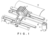
- Fig. 1 shows a carriage driving mechanism for an ordinary serial-dot printer, in which printing to a printing medium 13 (e.g. paper) is made by converting the rotational motion of a carriage drive motor 4 into a linear motion via a pulling member (e.g. belt) 10 and pulleys 11 so that a carriage 12 for mounting a printing head 7 can travel at a predetermined speed. Further, the positional control of the carriage 12, that is, the printing position control is effected on the basis of the output pulse of an encoder 5 mounted on the carriage drive motor 4.
- a printing medium 13 e.g. paper
- a pulling member e.g. belt
- Fig. 2 shows a driving pattern of the carriage drive motor 4 required when printing data for one line are printed.
- the printing operation is effected when the carriage 12 travels at a target constant speed.
- the travel distance of the carriage 12 from when a printing command is given to when the ends of wires reach the printing medium 13 to form dots (referred to as flight time) differs according to the travel speed of the carriage 12, thus resulting in a problem in that dot intervals are not equalized when the printing operation is made under the condition that the travel speed of the carriage 12 is not kept at a constant value.
- FIG. 3 is a simplified model view of the carriage drive mechanism, in which (a) shows the status where the carriage is driven in an ideal fashion without influence of elastic component and (b) shows the status where the carriage is accelerated in the arrow direction under influence of elastic component.
- a torque generated by the carriage drive motor 4 is transmitted to the carriage 12 under the condition that the belt is being expanded by ⁇ E on the travel direction side (contracted on the opposite side).
- a torque generated by the carriage motor 4 is transmitted to the carriage 12 under the condition that the belt is being contracted on the travel direction side (expanded on the opposite side).
- the expansion and contraction of the belt 10 are discussed only on the travel direction side.
- the reference numeral 502 denotes a graduation obtained by converting the encoder pulse generated by the encoder 5 for each constant revolutional angle ⁇ r of the carriage drive motor 4 into the travel distance of the carriage 12, in which the rotational angle ⁇ r corresponds to the travel stroke ⁇ x of the carriage 12.
- the printing command signals are given on the basis of the rotational angle of the carriage drive motor 4. Therefore, the printing command signals are generated on the assumption that the carriage 12 travels by ⁇ x whenever the carriage drive motor 4 rotates through the ⁇ r. In the conventional method, the correction has been started at this time according to the flight time and the travel speed of the carriage 12.
- the carriage 12 travels by a distance n x ⁇ x as illustrated, when the carriage motor 4 rotates by n x ⁇ r and an encoder pulse signal corresponding to the position Pn is generated.
- the carriage is driven under the influence of a certain elastic component of the belt as shown in Fig. 3(b)
- the carriage drive motor 4 rotates by n x ⁇ r during acceleration and an encoder pulse corresponding to the position Pn is generated, since the belt 10 is elongated by ⁇ E, there exists a problem in that the printed pots are offset by ⁇ E from the correct position Pn.
- the dot intervals can be kept constant.
- the expansion and contraction rate varies in such a way that the belt is expanded during acceleration, kept zero at a constant speed, and contracted during deceleration, the dot intervals cannot be kept constant.
- the object of the present invention is to provide a printing control system which can equalize dot intervals even if printing operation is effected during acceleration or deceleration of the carriage.
- the printing control system is characterized in that the system is provided with correcting means for correcting the printing operation in accordance with the relationship between the expansion and contraction rate of the pulling member and the travel speed of the printing head, and correcting means for correcting the printing operation in accordance with the relationship between the time from when printing commands are given to when dots are formed on the printing medium and the travel speed of the printing head.
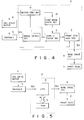
- Fig. 4 is a block diagram showing a printing control system for a wire dot printer according to the present invention.
- the reference numeral 4 denotes a carriage drive motor.
- the rotational angle of this carriage drive motor 4 is detected by an encoder 5.
- the encoder 5 generates an encoder pulse signal 501 and inputs the generated signal to a control section A for each predetermined rotational angle of the carriage drive motor 4.
- the control section A generates a printing command signal 301 on the basis of the pulse signal 501 from the encoder 5 to actuate a printing head 7 via a wire driving circuit 6 for printing operation.
- Fig. 5 shows a practical example of the control section A, which comprises a CPU 8 and a ROM 9.
- the CPU 8 executes processing (described later) in accordance with control programs written in the ROM 9.
- Fig. 4 is a block diagram showing the processing functions of the control section A.
- a speed detecting section 1 of the control section A measures a period T of the encoder pulse signal 501 from the encoder 5.
- This period T is a time duration required when the carriage drive motor 4 rotates through a predetermined unit angle. Therefore, the period T corresponds to the rotational speed of the drive motor 4 and further the travel speed V of the carriage.
- a correction value table indicative of the relationship between the period T (i.e. rotational speed) of the encoder pulse signal 501 and the correction value of the printing timing as shown in Table 1 is stored.
- a correction value deciding section 2 shown in Fig. 4 selects a correction value corresponding to the period T measured by the speed detecting section 1 on the basis of the correction value table.
- the printing command generating section 3 starts to measure time from when receiving the encoder pulse signal 501 from the encoder 5, and generates the printing command signal 301 when a time corresponding to a correction value given by the correction value deciding section 2 has elapsed.
- a motor control section 14 controls the required printing operation of the carriage drive motor 4, which accelerates the carriage drive motor 4 to a target speed, keeps the target speed thereafter, and decelerates the motor 4 so as to be stopped at a predetermined position.
- a control mode discriminating section 15 discriminates whether the control mode of the carriage drive motor 4 is acceleration, constant speed or deceleration, and transmits a signal to the correction value deciding section 2.
- the correction value deciding section 2 selects a correction value corresponding to the period T measured by the speed detecting section 1 and the control mode discriminated by the control mode discriminating section 15, on the basis of the correction value table.
- the relationship between the correction value for correcting the expansion and contraction of the belt 10 and the rotational speed is as follows:
- This value is a correction value corresponding to the speed V.
- a time point delayed by the correction value Te from the detection signal of the up-edge of the encoder pulse signal 501 is a time point at which the carriage 12 reaches a correct printing position.
- the correction value Te is a negative value in the case of deceleration.
- a time point a correction value Te before the time point when the up-edge of the encoder pulse signal 501 is detected is a time point at which the carriage 12 reaches a correct printing position.
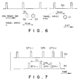
- the relationship between the correction value for correcting error due to flight time and the rotational speed is as follows:
- the position of the printing head 7 obtained when the carriage travels at the maximum speed V max is determined as a reference value, and the correction is made in such a way that the positions of the printing head 7 at the travel speeds other than the maximum speed are arranged at regular intervals beginning from the reference position.
- the encoder pulse signals 501 are generated at regular distance intervals but time intervals becoming shorter and shorter.
- the printing dot position D1 is offset by S max from the up-edge thereof.
- the printing dot position D2 is offset by S V from the up-edge position. The correction is made in such a way that the offset S V at the speed V becomes equal to the offset S max at the maximum speed V max ; that is, the printing dot position at the speed V is corrected to the position D3 to equalize the respective printing dot intervals.
- Tf Tfly ⁇ (V max - V)/V
- both the correction values for correcting error due to the expansion and contraction of the pulling member and for correcting error due to the flight time can be expressed as functions with respect to the travel speed V (the period T of the encoder pulse signal 501) of the carriage 12.
- Fig. 7 shows the encoder pulse signal 501 and the printing command signal 301 along the time axis.
- correction values Te and Tf corresponding to the period T are selected from the correction value table (corresponding to Table 1) in the ROM 9. If the carriage is being accelerated and the period T is tn as shown in Fig. 7, teACCn is selected as the correction value Te and tfn is selected as Tf (in step 63).
- Tdly Te + Tf
- Tdly teACCn + tfn
- the suffixes of the reference numerals of the pulse train represent the order of the pulse generation.
- the suffixes of the symbols of the period T simply represent the correspondence to the correction values, without determining the order of the changes in carriage speed such as acceleration or deceleration.
- the carriage 12 is shifted by ⁇ E during the correct time duration Te with respect to the belt expansion and contraction, and reaches the position Pn. Thereafter, the carriage is further moved by a distance corresponding to the speed difference between the maximum speed V max and the current speed V during the correct time duration Tf with respect to the flight time.
- the printing command signal 301 is generated, so that the intervals of the printed dots are controlled so as to be always equalized. In other words, the expansion and contraction of the pulling member is virtually cancelled by the correction corresponding to the expansion and contraction of the pulling member, and additionally the flight time can be virtually changed according to the speed by the correction corresponding to the flight time.
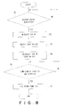
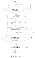
- Fig. 10 is a flowchart showing the operation of the second embodiment of the present invention.
- Table 2 is a correction value table used for this second embodiment, in which numerical values obtained by previously adding the correction values for correcting error caused by the expansion and contraction of the belt 10 and that for correcting error caused by the flight time are stored.
- TABLE 2 PERIOD T Tdly ACCEL DECEL t0 tdACC0 tdBRK0 t1 tdACC1 tdBRK1 t2 tdACC2 tdBRK2 . . . . tn-1 tdACCn-1 tdBRKn-1 tn tdACCn tdBRKn tn+1 tdACCn+1 tdBRKn+1 . . . . .
- the period T between the preceding encoder pulse signal EPn-1 and the current encoder pulse signal EPn is measured (in step 82), and a correction value Tdly corresponding to the period T is selected from the Table 2 in the ROM 9. If the period T is tn during acceleration as shown in Fig. 7, tdACCn is selected as the correction value Tdly (in step 83).
- step 84 If control confirms that the time of the correction value Tdly has elapsed from when the encoder pulse signal EPn was generated (in step 84), the printing command signal FPn is generated (in step 85).
- FIG. 11 is a flowchart showing the operation of the third embodiment
- Table 3 is a correction value table used for this third embodiment.
- the period between the preceding encoder pulse signal EPn-1 and the current encoder pulse signal EPn is measured (in step 92), and the correction value TORG corresponding to the period T and the offset value Tos are selected from the Table 3 in the ROM 9. For instance, if the period T during acceleration is tn as shown in Fig. 7, the correction values tdACCn and ton are selected as TORG and Tos, respectively (in step 93).
- Tdly TORG + Tos
- Tdly tdACCn + ton
- step 95 when the total correction time Tdly has elapsed after the encoder pulse signal EPn was generated (in step 95), the printing command signal FPn is generated (in step 96).
- the correction value is always kept at a positive value by introducing the offset value Tos, the correction can be made even if the belt contraction rate during deceleration is large.
- the correction is executed on the assumption that one printing command signal is generated for each encoder pulse signal.
- the correction is executed for the divided or multiplied output signal.
- the printing command signal can be corrected in such a way that both the influences of flight time and belt expansion and contraction can be eliminated, the printing dot intervals can be kept constant at all the times, thus realizing a high speed printing under excellent printing quality such that the printing operation can be effected even when the carriage is being accelerated or decelerated.
- Fig. 12 shows the relationship between the speed pattern of the carriage 12 and the belt expansion and contraction when printing data for one line are printed.
- a trapezoidal pattern as shown in Fig. 12 has conventionally been adopted.
- the belt expansion and contraction conditions are as follows:
- the motor speed is controlled so as to be smoothly changed from a predetermined speed V1 to a target speed; that is, the motor speed is controlled in such a way that the acceleration or the belt expansion rate decreases gradually (e.g. in proportion to the difference between the current speed and the target speed).
- the motor speed it is possible to prevent the time intervals of the printing command signal 301 from being reduced extremely.
- the motor speed is controlled in such a way that the deceleration or the belt contraction rate increases gradually (e.g. in proportion to the difference between the current speed and the target speed).
Landscapes
- Character Spaces And Line Spaces In Printers (AREA)
Abstract
Description
- The present invention relates to a printing control system suitable for a printer such as a serial-dot printer by which printing operation is effected by shifting a printing head.
- Fig. 1 shows a carriage driving mechanism for an ordinary serial-dot printer, in which printing to a printing medium 13 (e.g. paper) is made by converting the rotational motion of a
carriage drive motor 4 into a linear motion via a pulling member (e.g. belt) 10 andpulleys 11 so that acarriage 12 for mounting aprinting head 7 can travel at a predetermined speed. Further, the positional control of thecarriage 12, that is, the printing position control is effected on the basis of the output pulse of anencoder 5 mounted on thecarriage drive motor 4. - Fig. 2 shows a driving pattern of the
carriage drive motor 4 required when printing data for one line are printed. - In general, the printing operation is effected when the
carriage 12 travels at a target constant speed. However, it is possible to realize a high speed printing if the printing operation is effected when thecarriage 12 is being accelerated from a standstill to a constant speed or when being decelerated from a constant speed to a standstill. - In the serial-dot printer such as a wire dot printer in particular, however, the travel distance of the
carriage 12 from when a printing command is given to when the ends of wires reach theprinting medium 13 to form dots (referred to as flight time) differs according to the travel speed of thecarriage 12, thus resulting in a problem in that dot intervals are not equalized when the printing operation is made under the condition that the travel speed of thecarriage 12 is not kept at a constant value. - To overcome this problem, conventionally a delay time is determined according to the flight time and the carriage travel speed, and the printing command is given after the delay time has elapsed for compensation, as disclosed in Japanese Published Unexamined (Kokai) Patent Appli. No. 55-85984.
- As another serious problem, however, there exists the influence of expansion and contraction of the pulling member, with the result that the dot intervals will not be equalized when the printing operation is effected during the acceleration or deceleration of the
carriage 12. - A
belt 10 is typically used as the pulling member, and the belt is usually provided with an elastic component. Fig. 3 is a simplified model view of the carriage drive mechanism, in which (a) shows the status where the carriage is driven in an ideal fashion without influence of elastic component and (b) shows the status where the carriage is accelerated in the arrow direction under influence of elastic component. In the case shown in Fig. 3(b), a torque generated by thecarriage drive motor 4 is transmitted to thecarriage 12 under the condition that the belt is being expanded by ΔE on the travel direction side (contracted on the opposite side). On the other hand, when decelerated, a torque generated by thecarriage motor 4 is transmitted to thecarriage 12 under the condition that the belt is being contracted on the travel direction side (expanded on the opposite side). In the description below, the expansion and contraction of thebelt 10 are discussed only on the travel direction side. - In Fig. 3, the
reference numeral 502 denotes a graduation obtained by converting the encoder pulse generated by theencoder 5 for each constant revolutional angle Δr of thecarriage drive motor 4 into the travel distance of thecarriage 12, in which the rotational angle Δr corresponds to the travel stroke Δx of thecarriage 12. In general, the printing command signals are given on the basis of the rotational angle of thecarriage drive motor 4. Therefore, the printing command signals are generated on the assumption that thecarriage 12 travels by Δx whenever thecarriage drive motor 4 rotates through the Δr. In the conventional method, the correction has been started at this time according to the flight time and the travel speed of thecarriage 12. - In the case where the carriage is driven ideally without any elastic component of the belt as shown in Fig. 3(a), the
carriage 12 travels by a distance n x Δx as illustrated, when thecarriage motor 4 rotates by n x Δr and an encoder pulse signal corresponding to the position Pn is generated. In the case where the carriage is driven under the influence of a certain elastic component of the belt as shown in Fig. 3(b), when thecarriage drive motor 4 rotates by n x Δr during acceleration and an encoder pulse corresponding to the position Pn is generated, since thebelt 10 is elongated by ΔE, there exists a problem in that the printed pots are offset by ΔE from the correct position Pn. - If the rate of the expansion and contraction of the belt is constant, the dot intervals can be kept constant. However, since the expansion and contraction rate varies in such a way that the belt is expanded during acceleration, kept zero at a constant speed, and contracted during deceleration, the dot intervals cannot be kept constant.
- As described above, there are two factors which cause the dot intervals to be unequalized when the printing operation is performed during acceleration or deceleration as follows:
- * the factor caused by the flight time
- * the factor caused by the expansion and contraction of the pulling member
- Accordingly, the object of the present invention is to provide a printing control system which can equalize dot intervals even if printing operation is effected during acceleration or deceleration of the carriage.
- The printing control system according to the present invention is characterized in that the system is provided with correcting means for correcting the printing operation in accordance with the relationship between the expansion and contraction rate of the pulling member and the travel speed of the printing head, and correcting means for correcting the printing operation in accordance with the relationship between the time from when printing commands are given to when dots are formed on the printing medium and the travel speed of the printing head.
- In the construction as described above, when the printing operation is effected during acceleration from a standstill to a constant speed or deceleration from a constant speed to a standstill,
- * the expansion and contraction of the pulling member can be cancelled virtually by the correction according to the expansion and contraction rate of the pulling member; and
- * the flight time can be changed virtually according to the carriage speed by the correction according to the flight time.
-
- Fig. 1 is a perspective view diagrammatically showing the construction of a carriage drive mechanism of the general serial-dot printer;
- Fig. 2 is a diagram showing a change pattern of the general carriage speed;
- Fig. 3 is an illustration showing a carriage drive system as a model form;
- Fig. 4 is a block diagram showing an embodiment of the printing control system according to the present invention;
- Fig. 5 is a block diagram showing a practical embodiment of the control section A shown in Fig. 4;
- Fig. 6 is a view for assistance in explaining the correction operation related to the flight time in the embodiment shown in Fig. 4;
- Fig. 7 is a timing chart showing the relationship between the encoder pulse signal and the printing command signal;
- Fig. 8 is a flowchart for assistance in explaining the operation of the embodiment shown in Fig. 4;
- Fig. 9 is an illustration for assistance in explaining the operation of the embodiment shown in Fig. 4;
- Fig. 10 is a flowchart for assistance in explaining the operation of the second embodiment of the present invention;
- Fig. 11 is a flowchart for assistance in explaining the operation of the third embodiment of the present invention;
- Fig. 12 is a timing chart showing the relationship between the general carriage speed pattern and the belt expansion and contraction rate;
- Fig. 13 is a timing chart showing the relationship between the encoder pulse signal and the printing command signal in the speed pattern shown in Fig. 12; and
- Fig. 14 is a timing chart showing the relationship between the desirable carriage speed pattern and the belt expansion and contraction rate.
-
- One embodiment of the present invention will be described hereinbelow in detail with reference to the drawings. Fig. 4 is a block diagram showing a printing control system for a wire dot printer according to the present invention. In Fig. 4, the
reference numeral 4 denotes a carriage drive motor. The rotational angle of thiscarriage drive motor 4 is detected by anencoder 5. Theencoder 5 generates anencoder pulse signal 501 and inputs the generated signal to a control section A for each predetermined rotational angle of thecarriage drive motor 4. The control section A generates aprinting command signal 301 on the basis of thepulse signal 501 from theencoder 5 to actuate aprinting head 7 via awire driving circuit 6 for printing operation. - Fig. 5 shows a practical example of the control section A, which comprises a
CPU 8 and aROM 9. TheCPU 8 executes processing (described later) in accordance with control programs written in theROM 9. Fig. 4 is a block diagram showing the processing functions of the control section A. - In Fig. 4, a
speed detecting section 1 of the control section A measures a period T of theencoder pulse signal 501 from theencoder 5. This period T is a time duration required when thecarriage drive motor 4 rotates through a predetermined unit angle. Therefore, the period T corresponds to the rotational speed of thedrive motor 4 and further the travel speed V of the carriage. In theROM 9, a correction value table indicative of the relationship between the period T (i.e. rotational speed) of theencoder pulse signal 501 and the correction value of the printing timing as shown in Table 1 is stored. A correctionvalue deciding section 2 shown in Fig. 4 selects a correction value corresponding to the period T measured by thespeed detecting section 1 on the basis of the correction value table. The printingcommand generating section 3 starts to measure time from when receiving theencoder pulse signal 501 from theencoder 5, and generates theprinting command signal 301 when a time corresponding to a correction value given by the correctionvalue deciding section 2 has elapsed. - A
motor control section 14 controls the required printing operation of thecarriage drive motor 4, which accelerates thecarriage drive motor 4 to a target speed, keeps the target speed thereafter, and decelerates themotor 4 so as to be stopped at a predetermined position. A controlmode discriminating section 15 discriminates whether the control mode of thecarriage drive motor 4 is acceleration, constant speed or deceleration, and transmits a signal to the correctionvalue deciding section 2. The correctionvalue deciding section 2 selects a correction value corresponding to the period T measured by thespeed detecting section 1 and the control mode discriminated by the controlmode discriminating section 15, on the basis of the correction value table. - The relationship between the rotational speed and the correction value will be explained hereinbelow.
- First, the relationship between the correction value for correcting the expansion and contraction of the
belt 10 and the rotational speed is as follows: In Fig. 3(b), if the travel speed of thecarriage 12 during acceleration is designated by V and the elongation of thebelt 10 is designated by ΔE, the time Te required to shift thecarriage 12 by ΔE can be expressed as

This value is a correction value corresponding to the speed V. In other words, a time point delayed by the correction value Te from the detection signal of the up-edge of theencoder pulse signal 501 is a time point at which thecarriage 12 reaches a correct printing position. Further, if the belt is contracted during deceleration at the travel speed V of the carriage, since the belt elongation is designated by -ΔE, the time Te can be expressed as

- Therefore, in Table 1 the correction value Te is a negative value in the case of deceleration. In other words, a time point a correction value Te before the time point when the up-edge of the
encoder pulse signal 501 is detected is a time point at which thecarriage 12 reaches a correct printing position.TABLE 1 PERIOD T Te Tf ACCEL DECEL t0 teACC0 teBRK0 tf0 t1 teACC1 teBRK1 tf1 t2 teACC2 teBRK2 tf2 . . . . . . . . tn-1 teACCn-1 teBRKn-1 tfn-1 tn teACCn teBRKn tfn tn+1 teACCn+1 teBRKn+1 tfn+1 . . . . . . . . - On the other hand, the relationship between the correction value for correcting error due to flight time and the rotational speed is as follows: In this embodiment, the position of the
printing head 7 obtained when the carriage travels at the maximum speed Vmax is determined as a reference value, and the correction is made in such a way that the positions of theprinting head 7 at the travel speeds other than the maximum speed are arranged at regular intervals beginning from the reference position. For example, in Fig. 6, assuming that thecarriage 12 travels from the left to the right being accelerated, the encoder pulse signals 501 are generated at regular distance intervals but time intervals becoming shorter and shorter. At the maximum speed Vmax, where the printing is made by generating theprinting command signal 301 at the same time as when the up-edge of theencoder pulse signal 501 is detected, the printing dot position D1 is offset by Smax from the up-edge thereof. On the other hand, at the carriage travel speed V (at a certain time point of acceleration), where the printing is made by generating theprinting command signal 301 at the same time as when the up-edge of theencoder pulse signal 501 is detected without correction, the printing dot position D2 is offset by SV from the up-edge position. The correction is made in such a way that the offset SV at the speed V becomes equal to the offset Smax at the maximum speed Vmax; that is, the printing dot position at the speed V is corrected to the position D3 to equalize the respective printing dot intervals. - In Fig. 6, when the printing is made by moving the carriage at the maximum speed Vmax, the offset distance Smax from the up-edge of the
encoder pulse signal 501 can be expressed as

where Tfly denotes the flight time. - On the other hand, when the printing is made by moving the carriage at the speed V, the
printing command signal 301 is generated after the correction time Tf has elapsed from when the up-edge of theencoder pulse signal 501 is detected in order to match the offset SV with Smax. Therefore, the following formula can be established:

- Therefore, the correction time Tf can be expressed as

- As described above, both the correction values for correcting error due to the expansion and contraction of the pulling member and for correcting error due to the flight time can be expressed as functions with respect to the travel speed V (the period T of the encoder pulse signal 501) of the
carriage 12. - The control operation of the control section A will be explained hereinbelow with reference to Figs. 7 and 8. Fig. 7 shows the
encoder pulse signal 501 and theprinting command signal 301 along the time axis. - After the generation of the encoder pulse signal EPn-1 and the current encoder pulse signal EPn is measured (in step 62), and correction values Te and Tf corresponding to the period T are selected from the correction value table (corresponding to Table 1) in the
ROM 9. If the carriage is being accelerated and the period T is tn as shown in Fig. 7, teACCn is selected as the correction value Te and tfn is selected as Tf (in step 63). - The total correction value Tdly is obtained as

where if the period T is tn,
Tdly = teACCn + tfn (in step 64). After control confirms that the total correction time Tdly has elapsed from when the encoder signal EPn was generated (in step 65), a printing command signal FPn as shown in Fig. 7 is generated (in step 66). - Further, in Fig. 7, the suffixes of the reference numerals of the pulse train represent the order of the pulse generation. However, the suffixes of the symbols of the period T simply represent the correspondence to the correction values, without determining the order of the changes in carriage speed such as acceleration or deceleration.
- By the above-mentioned operation, as shown in Fig. 9, after the encoder pulse signal corresponding to the position Pn has been generated, the
carriage 12 is shifted by ΔE during the correct time duration Te with respect to the belt expansion and contraction, and reaches the position Pn. Thereafter, the carriage is further moved by a distance corresponding to the speed difference between the maximum speed Vmax and the current speed V during the correct time duration Tf with respect to the flight time. Immediately after the above carriage shift motion, theprinting command signal 301 is generated, so that the intervals of the printed dots are controlled so as to be always equalized. In other words, the expansion and contraction of the pulling member is virtually cancelled by the correction corresponding to the expansion and contraction of the pulling member, and additionally the flight time can be virtually changed according to the speed by the correction corresponding to the flight time. - A second embodiment of the second embodiment will be explained hereinbelow with reference to Figs. 7 and 10. Fig. 10 is a flowchart showing the operation of the second embodiment of the present invention. Table 2 is a correction value table used for this second embodiment, in which numerical values obtained by previously adding the correction values for correcting error caused by the expansion and contraction of the
belt 10 and that for correcting error caused by the flight time are stored.TABLE 2 PERIOD T Tdly ACCEL DECEL t0 tdACC0 tdBRK0 t1 tdACC1 tdBRK1 t2 tdACC2 tdBRK2 . . . . . . tn-1 tdACCn-1 tdBRKn-1 tn tdACCn tdBRKn tn+1 tdACCn+1 tdBRKn+1 . . . . . . - In this embodiment, after the generation of the encoder pulse signal EPn has been confirmed (in
step 81 in Fig. 10), the period T between the preceding encoder pulse signal EPn-1 and the current encoder pulse signal EPn is measured (in step 82), and a correction value Tdly corresponding to the period T is selected from the Table 2 in theROM 9. If the period T is tn during acceleration as shown in Fig. 7, tdACCn is selected as the correction value Tdly (in step 83). - If control confirms that the time of the correction value Tdly has elapsed from when the encoder pulse signal EPn was generated (in step 84), the printing command signal FPn is generated (in step 85).
- In this embodiment, it is possible to shorten the processing time, because it is unnecessary for the CPU to execute addition processing of the correction value for correcting error due to the expansion and contraction of the belt and that for correcting error due to the flight time. Additionally, since the number of data constituting the table is small, it is possible to reduce the number of bytes required for the
ROM 9. - A third embodiment of the present invention will be described hereinbelow with reference to Figs. 7 and 11. Fig. 11 is a flowchart showing the operation of the third embodiment, and Table 3 is a correction value table used for this third embodiment.
TABLE 3 PERIOD T TORG Tos ACCEL DECEL t0 tdACC0 tdBRK0 to0 t1 tdACC1 tdBRK1 to1 t2 tdACC2 tdBRK2 to2 . . . . . . . . tn-1 tdACCn-1 tdBRKn-1 ton-1 tn tdACCn tdBRKn ton tn+1 tdACCn+1 tdBRKn+1 ton+1 . . . . . . . . - When the
belt 10 is contracted during deceleration, the correction value corresponding to the expansion and contraction of thebelt 10 becomes negative. Therefore, if the contraction rate of thebelt 10 during deceleration is large, there exists the case where the sum total of the negative correction value for the belt expansion and contraction and the correction value for the flight time becomes eventually a negative value. This negative correction value indicates that theprinting command signal 301 must be generated before theencoder pulse signal 501 is generated, which is practically impossible. To overcome this problem, therefore, in this embodiment, an offset time Tos having a value proportional to the inverse number of the speed is introduced in order that the correction table can be constructed in such a way that the total time of the offset time Tos and the correction time TORG becomes always positive. Further, TORG corresponds to Tdly in Table 2. - In this embodiment, after the generation of the encoder pulse signal EPn has been confirmed (in step 91) in Fig. 11, the period between the preceding encoder pulse signal EPn-1 and the current encoder pulse signal EPn is measured (in step 92), and the correction value TORG corresponding to the period T and the offset value Tos are selected from the Table 3 in the
ROM 9. For instance, if the period T during acceleration is tn as shown in Fig. 7, the correction values tdACCn and ton are selected as TORG and Tos, respectively (in step 93). - Thereafter, the total correction value Tdly is obtained as (in step 94)

Here, if the period T is tn,

- Further, when the total correction time Tdly has elapsed after the encoder pulse signal EPn was generated (in step 95), the printing command signal FPn is generated (in step 96).
- In this embodiment, since the correction value is always kept at a positive value by introducing the offset value Tos, the correction can be made even if the belt contraction rate during deceleration is large.
- In the above-mentioned embodiment, the correction is executed on the assumption that one printing command signal is generated for each encoder pulse signal. However, where the encoder pulse signal is divided or multiplied in frequency, the correction is executed for the divided or multiplied output signal.
- As described above, since the printing command signal can be corrected in such a way that both the influences of flight time and belt expansion and contraction can be eliminated, the printing dot intervals can be kept constant at all the times, thus realizing a high speed printing under excellent printing quality such that the printing operation can be effected even when the carriage is being accelerated or decelerated.
- On the other hand, in order to improve the reliability of the printing timing correction related to the belt expansion and contraction, it is preferable to adopt a special pattern as the carriage speed pattern. This pattern will be described hereinbelow with reference to Figs. 12 and 14.
- Fig. 12 shows the relationship between the speed pattern of the
carriage 12 and the belt expansion and contraction when printing data for one line are printed. In general, a trapezoidal pattern as shown in Fig. 12 has conventionally been adopted. In this case, since the acceleration and deceleration are both a uniformly accelerated motion, the belt expansion and contraction conditions are as follows: - * During acceleration, the belt is expanded at a constant rate proportional to the acceleration rate;
- * During constant speed, the belt expansion rate is roughly zero; and
- * During deceleration, the belt is contracted at a constant rate proportional to the deceleration rate.
- Where the correction is executed according to the belt expansion and contraction conditions of the above-mentioned speed pattern, there arises a problem when the acceleration changes to the constant speed or when the constant speed changes to the deceleration. Here, for simplification, only the correction according to the belt expansion and contraction when the acceleration changes to the constant speed will be taken into account.
- In the belt expansion and contraction conditions shown in Fig. 12, since the belt expansion rate changes abruptly from Eacc to zero the instant the acceleration changes to the constant speed, the correction rate also changes from Tn to zero as shown in Fig. 13. Therefore, the intervals between the printing command signals 301 becomes extremely short, in comparison with the succeeding and preceding intervals, beyond the ordinary response speed of the printing head, so that there exists a problem in that the printing is disabled.
- To overcome this problem, as shown in Fig. 14, the motor speed is controlled so as to be smoothly changed from a predetermined speed V₁ to a target speed; that is, the motor speed is controlled in such a way that the acceleration or the belt expansion rate decreases gradually (e.g. in proportion to the difference between the current speed and the target speed). By controlling the motor speed, it is possible to prevent the time intervals of the
printing command signal 301 from being reduced extremely. - On the other hand, during deceleration, the motor speed is controlled in such a way that the deceleration or the belt contraction rate increases gradually (e.g. in proportion to the difference between the current speed and the target speed).
- The present invention is not limited to only the above-mentioned embodiments, various modifications of the present invention may be made without departing from the gist thereof.
Claims (6)
- A printing control system in which a printing head is moved by a pulling member coupled to a power source, and a printing command signal generated in response to a signal synchronized with motion of the power source is applied to the printing head, which comprises:
means for detecting moving speed of the printing head; and
means for correcting timing at which the printing command signal is generated, in association with both expansion and contraction rate of the pulling member and flight time at the detected moving speed. - The printing control system of claim 1, wherein said correcting means comprises:
means for generating a time correction value including an addition of a first correction time for correcting the generation timing of the printing command signal with respect to the expansion and contraction rate of the pulling member and a second correction time for correcting the generation timing of the printing command signal with respect to the flight time, both according to the detected moving speed, in accordance with a predetermined relationship between the first correction time and the moving speed of the printing head and another predetermined relationship between the second correction time and the moving speed of the printing head; and
means for controlling time intervals from when the synchronizing signal is received to when the printing command signal is generated, on the basis of the generated time correction value. - The printing control system of claim 1, wherein said correcting means comprises:
means for generating a time correction value including the correction time corresponding to the detected moving speed, in accordance with a predetermined relationship between the correction time for correcting the generation timing of the printing command signal with respect to both the expansion and contraction rate of the pulling member and the flight time, and the moving speed of the printing head; and
means for controlling time intervals from when the synchronizing signal is received to when the printing command signal is generated, on the basis of the generated time correction value. - The printing control system of either claim 2 or 3, wherein said correcting means further comprises means for discriminating whether the printing head is being accelerated or decelerated; and wherein said correction value generating means generates different values as the correction value according to acceleration and deceleration discriminated by said discriminating means, even if the detected moving speed is the same.
- The printing control system of claim 4, wherein said correction value generating means decides an offset time corresponding to the detected moving speed in accordance with a predetermined inversely proportional relationship between the correction time and the detected moving speed; and the decided offset time is also included in the generated time correction value so that the generated time correction value becomes always a positive value, irrespective of that the printing head is being accelerated or decelerated.
- The printing control system of claim 1, which further comprises means for controlling the power source so that the acceleration of the printing head changes smoothly.
Applications Claiming Priority (3)
| Application Number | Priority Date | Filing Date | Title |
|---|---|---|---|
| JP124774/90 | 1990-05-15 | ||
| JP12477490 | 1990-05-15 | ||
| PCT/JP1991/000642 WO1991017892A1 (en) | 1990-05-15 | 1991-05-15 | Print controller |
Publications (3)
| Publication Number | Publication Date |
|---|---|
| EP0483371A1 true EP0483371A1 (en) | 1992-05-06 |
| EP0483371A4 EP0483371A4 (en) | 1993-02-24 |
| EP0483371B1 EP0483371B1 (en) | 1995-11-29 |
Family
ID=14893783
Family Applications (1)
| Application Number | Title | Priority Date | Filing Date |
|---|---|---|---|
| EP91909091A Expired - Lifetime EP0483371B1 (en) | 1990-05-15 | 1991-05-15 | Print controller |
Country Status (6)
| Country | Link |
|---|---|
| US (1) | US5288157A (en) |
| EP (1) | EP0483371B1 (en) |
| JP (1) | JP3248169B2 (en) |
| DE (1) | DE69114993T2 (en) |
| HK (1) | HK5497A (en) |
| WO (1) | WO1991017892A1 (en) |
Cited By (3)
| Publication number | Priority date | Publication date | Assignee | Title |
|---|---|---|---|---|
| EP0524619A3 (en) * | 1991-07-22 | 1993-09-29 | Seiko Epson Corporation | Method and apparatus for print control |
| EP1287992A2 (en) | 2001-08-27 | 2003-03-05 | Canon Kabushiki Kaisha | Ink jet printing apparatus and method |
| DE19919805C2 (en) * | 1998-04-30 | 2003-03-20 | Mutoh Ind Ltd | printing device |
Families Citing this family (9)
| Publication number | Priority date | Publication date | Assignee | Title |
|---|---|---|---|---|
| AU749771B2 (en) * | 1998-03-04 | 2002-07-04 | Ferag Ag | Device for exchanging roll supports on winding stations |
| US6601513B1 (en) * | 1999-05-25 | 2003-08-05 | Seiko Precision, Inc. | Motor control method and apparatus, time recorder having same and impact type printing apparatus |
| JP2001232859A (en) | 2000-02-21 | 2001-08-28 | Seiko Epson Corp | Bi-directional printing considering mechanical vibration of print head |
| US6609781B2 (en) | 2000-12-13 | 2003-08-26 | Lexmark International, Inc. | Printer system with encoder filtering arrangement and method for high frequency error reduction |
| JP3673745B2 (en) * | 2001-10-01 | 2005-07-20 | キヤノン株式会社 | Control device and method thereof, recording device and control method thereof |
| CN1321000C (en) | 2002-03-14 | 2007-06-13 | 精工爱普生株式会社 | Printing device, printing method and computer system |
| US7753465B2 (en) * | 2006-10-13 | 2010-07-13 | Lexmark International, Inc. | Method for generating a reference signal for use in an imaging apparatus |
| US8197022B2 (en) * | 2009-09-29 | 2012-06-12 | Eastman Kodak Company | Automated time of flight speed compensation |
| JP5845693B2 (en) * | 2011-07-29 | 2016-01-20 | ブラザー工業株式会社 | Conveying apparatus and image forming apparatus |
Family Cites Families (16)
| Publication number | Priority date | Publication date | Assignee | Title |
|---|---|---|---|---|
| US4533268A (en) * | 1982-10-27 | 1985-08-06 | Sanders Jr Roy C | Position indicator for high speed printers |
| US4522517A (en) * | 1983-11-10 | 1985-06-11 | Wade Kenneth B | Encoder system for dot matrix line printer |
| JPS6233662A (en) * | 1985-08-08 | 1987-02-13 | Alps Electric Co Ltd | Control system of motor for printer |
| JPH0611573B2 (en) * | 1985-09-18 | 1994-02-16 | キヤノン株式会社 | Recording device |
| US4844635A (en) * | 1985-12-11 | 1989-07-04 | International Business Machines Corp. | Wire fire control mechanism for a wire matrix printer |
| JP2563788B2 (en) * | 1986-03-07 | 1996-12-18 | セイコーエプソン株式会社 | Printer carriage control method |
| JPH0798409B2 (en) * | 1986-08-29 | 1995-10-25 | 沖電気工業株式会社 | Printer |
| JPS6423428A (en) * | 1987-07-20 | 1989-01-26 | Mitsubishi Electric Corp | Recording medium driver and focus tracking device in recording medium driver |
| JPS6490761A (en) * | 1987-10-01 | 1989-04-07 | Citizen Watch Co Ltd | Printer control system |
| JPH01103478A (en) * | 1987-10-16 | 1989-04-20 | Brother Ind Ltd | Printer |
| JPH01234280A (en) * | 1988-03-14 | 1989-09-19 | Nec Corp | Method and apparatus for controlling movement of printing head carrier |
| JPH0747347B2 (en) * | 1988-05-09 | 1995-05-24 | シャープ株式会社 | Reciprocating printing method |
| JP2536590B2 (en) * | 1988-05-20 | 1996-09-18 | 沖電気工業株式会社 | Printer printing method |
| JPH0270470A (en) * | 1988-09-06 | 1990-03-09 | Nec Corp | Printer |
| JPH02261678A (en) * | 1989-03-31 | 1990-10-24 | Brother Ind Ltd | Printer with function to correct misaligned print position in forward/backward printing process |
| US5116150A (en) * | 1991-01-09 | 1992-05-26 | Apple Computer, Inc. | Apparatus and method for mapping and aligning digital images onto printed media |
-
1991
- 1991-05-15 JP JP50878291A patent/JP3248169B2/en not_active Expired - Fee Related
- 1991-05-15 EP EP91909091A patent/EP0483371B1/en not_active Expired - Lifetime
- 1991-05-15 US US07/778,908 patent/US5288157A/en not_active Expired - Lifetime
- 1991-05-15 WO PCT/JP1991/000642 patent/WO1991017892A1/en not_active Ceased
- 1991-05-15 DE DE69114993T patent/DE69114993T2/en not_active Expired - Fee Related
-
1997
- 1997-01-09 HK HK5497A patent/HK5497A/en not_active IP Right Cessation
Cited By (7)
| Publication number | Priority date | Publication date | Assignee | Title |
|---|---|---|---|---|
| EP0524619A3 (en) * | 1991-07-22 | 1993-09-29 | Seiko Epson Corporation | Method and apparatus for print control |
| US5310272A (en) * | 1991-07-22 | 1994-05-10 | Seiko Epson Corporation | Printer timing controller and method |
| US5439301A (en) * | 1991-07-22 | 1995-08-08 | Seiko Epson Corporation | Printer controller and method thereof for a printhead assembly |
| DE19919805C2 (en) * | 1998-04-30 | 2003-03-20 | Mutoh Ind Ltd | printing device |
| EP1287992A2 (en) | 2001-08-27 | 2003-03-05 | Canon Kabushiki Kaisha | Ink jet printing apparatus and method |
| EP1287992A3 (en) * | 2001-08-27 | 2003-09-03 | Canon Kabushiki Kaisha | Ink jet printing apparatus and method |
| US6910752B2 (en) | 2001-08-27 | 2005-06-28 | Canon Kabushiki Kaisha | Ink jet printing apparatus and method for adjusting driving timing of ink ejection |
Also Published As
| Publication number | Publication date |
|---|---|
| EP0483371B1 (en) | 1995-11-29 |
| HK5497A (en) | 1997-01-17 |
| JP3248169B2 (en) | 2002-01-21 |
| US5288157A (en) | 1994-02-22 |
| WO1991017892A1 (en) | 1991-11-28 |
| DE69114993D1 (en) | 1996-01-11 |
| EP0483371A4 (en) | 1993-02-24 |
| DE69114993T2 (en) | 1996-06-20 |
Similar Documents
| Publication | Publication Date | Title |
|---|---|---|
| EP0483371B1 (en) | Print controller | |
| EP1287992B1 (en) | Ink jet printing apparatus and method | |
| JPWO1991017892A1 (en) | Printing control device | |
| US4832518A (en) | Apparatus for driving and controlling a printing head carriage | |
| US4493570A (en) | Control system for impact printer | |
| US5439301A (en) | Printer controller and method thereof for a printhead assembly | |
| EP0585581B1 (en) | Carriage motor controller for printer | |
| JPH0820138A (en) | Image forming device | |
| HK1003601B (en) | Carriage motor controller for printer | |
| JPS63112182A (en) | Printer device | |
| EP0431731B1 (en) | Friction-compensating mass motion controller | |
| JPH04310766A (en) | Printer | |
| JP3458718B2 (en) | Serial printer and operating method of serial printer | |
| JPH0448630B2 (en) | ||
| JPS588666A (en) | Bidirectional printing system of serial dot printer | |
| JPH01135674A (en) | Printer print control method | |
| JPH0515197A (en) | Drive control method for step motor | |
| US20060023025A1 (en) | Apparatus and method for controlling printing time | |
| JPH0580856A (en) | Motor controller | |
| JP2002219835A (en) | Printing control method and device | |
| JP2001334717A (en) | Recording control method and recording apparatus | |
| EP0061718B1 (en) | An adaptive high speed serial printer | |
| JP2540752B2 (en) | Stacker crane travel control device | |
| JPS6213362A (en) | Printing method in wire dot printer | |
| JP2988126B2 (en) | Carriage control device |
Legal Events
| Date | Code | Title | Description |
|---|---|---|---|
| PUAI | Public reference made under article 153(3) epc to a published international application that has entered the european phase |
Free format text: ORIGINAL CODE: 0009012 |
|
| 17P | Request for examination filed |
Effective date: 19920114 |
|
| AK | Designated contracting states |
Kind code of ref document: A1 Designated state(s): DE FR GB |
|
| A4 | Supplementary search report drawn up and despatched |
Effective date: 19930104 |
|
| AK | Designated contracting states |
Kind code of ref document: A4 Designated state(s): DE FR GB |
|
| RIN1 | Information on inventor provided before grant (corrected) |
Inventor name: TANAKA, HIROTOMO, C/O SEIKO EPSON CORPORATION |
|
| 17Q | First examination report despatched |
Effective date: 19940722 |
|
| GRAA | (expected) grant |
Free format text: ORIGINAL CODE: 0009210 |
|
| AK | Designated contracting states |
Kind code of ref document: B1 Designated state(s): DE FR GB |
|
| REF | Corresponds to: |
Ref document number: 69114993 Country of ref document: DE Date of ref document: 19960111 |
|
| ET | Fr: translation filed | ||
| PLBE | No opposition filed within time limit |
Free format text: ORIGINAL CODE: 0009261 |
|
| STAA | Information on the status of an ep patent application or granted ep patent |
Free format text: STATUS: NO OPPOSITION FILED WITHIN TIME LIMIT |
|
| 26N | No opposition filed | ||
| REG | Reference to a national code |
Ref country code: GB Ref legal event code: IF02 |
|
| PGFP | Annual fee paid to national office [announced via postgrant information from national office to epo] |
Ref country code: GB Payment date: 20060510 Year of fee payment: 16 |
|
| PGFP | Annual fee paid to national office [announced via postgrant information from national office to epo] |
Ref country code: DE Payment date: 20060511 Year of fee payment: 16 |
|
| PGFP | Annual fee paid to national office [announced via postgrant information from national office to epo] |
Ref country code: FR Payment date: 20060515 Year of fee payment: 16 |
|
| GBPC | Gb: european patent ceased through non-payment of renewal fee |
Effective date: 20070515 |
|
| REG | Reference to a national code |
Ref country code: FR Ref legal event code: ST Effective date: 20080131 |
|
| PG25 | Lapsed in a contracting state [announced via postgrant information from national office to epo] |
Ref country code: DE Free format text: LAPSE BECAUSE OF NON-PAYMENT OF DUE FEES Effective date: 20071201 |
|
| PG25 | Lapsed in a contracting state [announced via postgrant information from national office to epo] |
Ref country code: GB Free format text: LAPSE BECAUSE OF NON-PAYMENT OF DUE FEES Effective date: 20070515 |
|
| PG25 | Lapsed in a contracting state [announced via postgrant information from national office to epo] |
Ref country code: FR Free format text: LAPSE BECAUSE OF NON-PAYMENT OF DUE FEES Effective date: 20070531 |