EP0479519B1 - Coupling device for pipeline heating system - Google Patents
Coupling device for pipeline heating system Download PDFInfo
- Publication number
- EP0479519B1 EP0479519B1 EP91308915A EP91308915A EP0479519B1 EP 0479519 B1 EP0479519 B1 EP 0479519B1 EP 91308915 A EP91308915 A EP 91308915A EP 91308915 A EP91308915 A EP 91308915A EP 0479519 B1 EP0479519 B1 EP 0479519B1
- Authority
- EP
- European Patent Office
- Prior art keywords
- pipeline
- electrically
- segment
- pipe
- conducting pipe
- Prior art date
- Legal status (The legal status is an assumption and is not a legal conclusion. Google has not performed a legal analysis and makes no representation as to the accuracy of the status listed.)
- Expired - Lifetime
Links
- 230000008878 coupling Effects 0.000 title claims description 12
- 238000010168 coupling process Methods 0.000 title claims description 12
- 238000005859 coupling reaction Methods 0.000 title claims description 12
- 238000010438 heat treatment Methods 0.000 title claims description 11
- 239000012530 fluid Substances 0.000 claims description 24
- 229910000831 Steel Inorganic materials 0.000 claims description 10
- 239000010959 steel Substances 0.000 claims description 10
- 239000002904 solvent Substances 0.000 claims description 6
- 230000005611 electricity Effects 0.000 claims description 5
- 238000002347 injection Methods 0.000 claims description 5
- 239000007924 injection Substances 0.000 claims description 5
- XLYOFNOQVPJJNP-UHFFFAOYSA-N water Substances O XLYOFNOQVPJJNP-UHFFFAOYSA-N 0.000 claims description 5
- 239000003570 air Substances 0.000 claims description 4
- 238000007789 sealing Methods 0.000 claims description 4
- 238000004519 manufacturing process Methods 0.000 description 14
- 239000004020 conductor Substances 0.000 description 3
- 230000008021 deposition Effects 0.000 description 3
- 239000000463 material Substances 0.000 description 3
- 239000003208 petroleum Substances 0.000 description 3
- 230000015572 biosynthetic process Effects 0.000 description 2
- 238000006073 displacement reaction Methods 0.000 description 2
- 230000000694 effects Effects 0.000 description 2
- 229920001971 elastomer Polymers 0.000 description 2
- 239000000806 elastomer Substances 0.000 description 2
- 238000000034 method Methods 0.000 description 2
- 229920002647 polyamide Polymers 0.000 description 2
- 229920001343 polytetrafluoroethylene Polymers 0.000 description 2
- 239000004810 polytetrafluoroethylene Substances 0.000 description 2
- 239000004952 Polyamide Substances 0.000 description 1
- 239000000654 additive Substances 0.000 description 1
- 230000000996 additive effect Effects 0.000 description 1
- 239000011248 coating agent Substances 0.000 description 1
- 238000000576 coating method Methods 0.000 description 1
- 239000012634 fragment Substances 0.000 description 1
- 238000009434 installation Methods 0.000 description 1
- 238000002955 isolation Methods 0.000 description 1
- 239000012188 paraffin wax Substances 0.000 description 1
- 230000035515 penetration Effects 0.000 description 1
- -1 polytetrafluoroethylene Polymers 0.000 description 1
- 238000005086 pumping Methods 0.000 description 1
- 230000002787 reinforcement Effects 0.000 description 1
- 239000013535 sea water Substances 0.000 description 1
- 239000000243 solution Substances 0.000 description 1
Images

Classifications
-
- F—MECHANICAL ENGINEERING; LIGHTING; HEATING; WEAPONS; BLASTING
- F16—ENGINEERING ELEMENTS AND UNITS; GENERAL MEASURES FOR PRODUCING AND MAINTAINING EFFECTIVE FUNCTIONING OF MACHINES OR INSTALLATIONS; THERMAL INSULATION IN GENERAL
- F16L—PIPES; JOINTS OR FITTINGS FOR PIPES; SUPPORTS FOR PIPES, CABLES OR PROTECTIVE TUBING; MEANS FOR THERMAL INSULATION IN GENERAL
- F16L25/00—Construction or details of pipe joints not provided for in, or of interest apart from, groups F16L13/00 - F16L23/00
- F16L25/01—Construction or details of pipe joints not provided for in, or of interest apart from, groups F16L13/00 - F16L23/00 specially adapted for realising electrical conduction between the two pipe ends of the joint or between parts thereof
-
- F—MECHANICAL ENGINEERING; LIGHTING; HEATING; WEAPONS; BLASTING
- F16—ENGINEERING ELEMENTS AND UNITS; GENERAL MEASURES FOR PRODUCING AND MAINTAINING EFFECTIVE FUNCTIONING OF MACHINES OR INSTALLATIONS; THERMAL INSULATION IN GENERAL
- F16L—PIPES; JOINTS OR FITTINGS FOR PIPES; SUPPORTS FOR PIPES, CABLES OR PROTECTIVE TUBING; MEANS FOR THERMAL INSULATION IN GENERAL
- F16L53/00—Heating of pipes or pipe systems; Cooling of pipes or pipe systems
- F16L53/30—Heating of pipes or pipe systems
- F16L53/35—Ohmic-resistance heating
- F16L53/37—Ohmic-resistance heating the heating current flowing directly through the pipe to be heated
Definitions
- This invention relates to a device for the coupling of fluid-carrying subsea pipelines, allowing for the passage of an electric current through same, with the purpose of electrically heating those pipelines for preventing or eliminating deposits of organic residues at the internal walls of said pipelines.
- a device may be adapted to allow for the utilization of electricity combined with the simultaneous injection of special fluids, such as solvents, air or steam.
- Another known alternative consists of adding, to the fluid being carried, a special additive or solvent so as to maintain the organic residues in solution.
- a third alternative to prevent or minimize the formation of residues at the pipeline walls includes maintaining said pipeline walls heated, so that the temperature differential between same and the environment will be sufficient to ensure the fluid flow.
- This invention relates to this last possibility, combining it, if required, with the use of special solvents for the fluid being transported.
- the technical problem to be overcome consists of finding a way of introducing electricity into the subsea pipelines, particularly when these pipelines are already installed at some hundreds of meters of depth.
- US Patent 4815769 in which is described a device to achieve the connection or distribution between fluid-carrying hoses and a heating element, with the purpose of preventing the fluid from congealing inside said hoses.
- a slot is opened in the wall, and a heating wire is inserted therein.
- One extremity of the wire is connected to and wound around a contact element, made of a heat-conducting material, which is lodged inside the hose; the other extremity extends outside the hose, and is connected to a heating wire of a connector.
- the assembly is covered by an isolating coating so as to form a compact block, constituting a hose element which can be heated.
- the production lines that is the connections between the well and the platform, are achieved by means of flexible pipelines.
- These flexible pipelines are formed basically by alternate layers of steel spirals intercalated with layers of an isolating material as, for instance, a polyamide-based elastomer.
- the internal steel layer is interlocked, whereas the outermost layer is constituted by a cross-shield, with the purpose of providing the pipeline with a stronger structural reinforcement, this whole set being coated with a polyamide layer.
- Another object of this invention is to provide a device allowing for the introduction of electric current in subsea production lines.
- Another object of this invention is to provide a device allowing for the simultaneous use of electric current and fluid injection in subsea production lines, with the purpose of eliminating and/or displacing obstructions caused by deposition of organic residues inside the lines.
- Still another object of this invention is to provide a device to achieve the electric connection between (a) the internal wall of a flexible pipeline and (b) a pipeline for injection of special fluids, to be coupled to the production line.
- this invention provides a pipeline with a heating system, characterized by including a segment of electrically-conducting pipe which is introduced in a terminal pipe of the flexible pipeline and is maintained spaced from the internal steel layer of said flexible pipeline by means of electrically-isolating means, said pipe segment having at its end within the flexible pipeline a fastening element which also achieves electric contact between the flexible pipeline and the segment of electrically-conducting pipe, said segment being adapted to be connected to a source of electric power.
- the other end of the electrically conducting pipe segment can be connected to an electric source or to an electric cable and can be fastened to the terminal pipe of the flexible pipeline by means of a sealing element and a coupling element, to ensure the tightness of the assembly to the penetration of moisture and sea water, or to the leaking of fluid from inside the production line while the obstruction is being eliminated.
- the drawings show a device which allows for the coupling of flexible pipelines for operation in a heating system for the pipelines, particularly in the case of transportation of fluids which are viscous and/or contain dissolved organic residues, through subsea facilities.
- the device allows for the introduction of an electric current in the internal steel mesh of said pipelines, generating sufficient heat to cause the displacement of organic residues deposited on the internal surface of the pipelines which would eventually lead to the obstruction of the pipelines, as well as to maintain the temperature differential between the transported fluid and the external environment between values adequate to ensure the fluid flow.
- the external mesh 2 and elastomer layers extend a little beyond the internal steel layer 3 and form an end 4 to allow for the coupling of the pipeline to other segments of flexible pipeline or to the inlet and outlet pipes of equipment sets installed at the platform, or at the manifolds, or else at the wellhead.
- These couplings are achieved by means of special clamps or brackets (not shown on Figures 1 and 2), which maintain those ends tightly fastened together.
- the device of this invention is introduced through the terminal pipe 1 so as to allow an electric current to flow in the internal steel layer 3 of said terminal pipe.
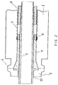
- FIG 2 shows in detail the device of the invention, lodged and fastened to the terminal pipe 1 shown on Figure 1.
- the electric contact between the two pipes - the terminal pipe and electrically-conducting pipe 5 - is achieved by means of a fastening element 8 affixed to the internal end of the segment 5 of electrically-conducting pipe which has a thickness sufficient to contact the internal steel layer 3 of the flexible pipeline.
- a terminal element 9 is coupled to the end 4 of the terminal pipe of the flexible pipeline, the terminal element 9 having the same external profile of said end 4, so as to allow for the fastening and coupling of the two edges by means of clamps or brackets, as already described.
- the terminal element 9 is isolated from the electrically-conducting pipe 5 by means of another sealing element 10, which also provides the electric isolation between the pipelines.
- the electrically-conducting pipe 5 may be connected to a bifurcation of a "T" or "Y” shape (not shown in the Figures), so as to allow for the introduction of the special fluid into the production line simultaneously with the application of electricity.
- a major advantage of the coupling device of this invention in relation to the electric connectors of the prior art, is that electricity is conducted through an electrically-conducting pipe which may allow for the simultaneous introduction of special fluids, such as solvents, air or water, thus making it possible to optimize the pipeline heating system, more particularly the use of heat for pipeline clearing.
- the combined use of heat and fluid injection provides that, as the displacement of the organic residue from the internal walls of the flexible pipeline is achieved, the solvent, the air, or the steam-generated by water heating helps to displace the block of residues (or its fragments), opening ways through those materials and making it possible consequently to displace the fluid, and to re-establish the conditions for restoring the regular production flow.
- Another advantage relates to the operational simplicity of the device and its coupling to already installed production lines, in addition to the low cost of manufacturing and installation, dispensing with the use of special equipment sets for its utilization.
- Still another advantage is that the combination of those resources permits the clearing of the pipeline without the temperature being too high, which could damage the structure of the pipeline carrying viscous fluids.
- the ideal is to maintain the temperature in the range of 40-60°C.
Landscapes
- Engineering & Computer Science (AREA)
- General Engineering & Computer Science (AREA)
- Mechanical Engineering (AREA)
- Pipe Accessories (AREA)
- Rigid Pipes And Flexible Pipes (AREA)
- Resistance Heating (AREA)
- Pipeline Systems (AREA)
Description
- This invention relates to a device for the coupling of fluid-carrying subsea pipelines, allowing for the passage of an electric current through same, with the purpose of electrically heating those pipelines for preventing or eliminating deposits of organic residues at the internal walls of said pipelines. Such a device may be adapted to allow for the utilization of electricity combined with the simultaneous injection of special fluids, such as solvents, air or steam.
- In the case of the operation with subsea facilities for transportation of fluids, particularly fluids which are viscous and/or contain organic residues, one of the problems to be faced concerns obstruction in the pipelines, due to the deposition of those residues on the internal walls of the pipelines, caused by the temperature differential between the environment and the fluid being transported.
- It is well-known that in regions of great water depths the temperature of the water reaches nearly 5°C. This may differ greatly from the temperatures of fluids being pumped through pipelines at those depths. The greater is this temperature differential the greater will be the extent of the above problems, since the tendency towards the formation of deposits will increase, leading to total obstruction of the pipeline.
- One alternative to overcome this problem consists of applying a pressure differential between the extremities of the pipeline with the purpose of forcing the fluid flow. However, when said pipelines are too long, the possibilities of utilization of that method become unfeasible, whether from the technical point of view due to the dimensions of the equipment, or from the economic point of view.
- Another known alternative consists of adding, to the fluid being carried, a special additive or solvent so as to maintain the organic residues in solution.
- A third alternative to prevent or minimize the formation of residues at the pipeline walls includes maintaining said pipeline walls heated, so that the temperature differential between same and the environment will be sufficient to ensure the fluid flow.
- This invention relates to this last possibility, combining it, if required, with the use of special solvents for the fluid being transported. The technical problem to be overcome consists of finding a way of introducing electricity into the subsea pipelines, particularly when these pipelines are already installed at some hundreds of meters of depth.
- It is well-known that, when an electric current is applied to an electric conductor, a certain quantity of energy is transformed into heat. This phenomenon is known as the Joule Effect and is widely applied in various technical areas.
- In the automotive industry, for instance, we may mention US Patent 4815769, in which is described a device to achieve the connection or distribution between fluid-carrying hoses and a heating element, with the purpose of preventing the fluid from congealing inside said hoses. In a portion of the hose a slot is opened in the wall, and a heating wire is inserted therein. One extremity of the wire is connected to and wound around a contact element, made of a heat-conducting material, which is lodged inside the hose; the other extremity extends outside the hose, and is connected to a heating wire of a connector. The assembly is covered by an isolating coating so as to form a compact block, constituting a hose element which can be heated.
- In the area of petroleum production the Joule effect is utilized in our Brazilian Application PI 8692278, to heat a petroleum production string inside a well, the production flow of which was interrupted due to paraffin deposition inside the string, which prevented the pumping rod from moving.
- The process, however, comes up against technical difficulties for application in subsea wells.
- Due to the handling facility in the offshore petroleum production systems, the production lines, that is the connections between the well and the platform, are achieved by means of flexible pipelines. These flexible pipelines are formed basically by alternate layers of steel spirals intercalated with layers of an isolating material as, for instance, a polyamide-based elastomer. The internal steel layer is interlocked, whereas the outermost layer is constituted by a cross-shield, with the purpose of providing the pipeline with a stronger structural reinforcement, this whole set being coated with a polyamide layer.
- Thus, it is one object of this invention to make an electric current cross the steel shield of the flexible pipeline, similarly to an electric conductor, generating energy and dissipating a certain quantity of heat to the pipeline and to the fluid contained therein, for maintaining the temperature differential between the environment and the production line, so as not to interrupt the fluid flow.
- Another object of this invention is to provide a device allowing for the introduction of electric current in subsea production lines.
- Another object of this invention is to provide a device allowing for the simultaneous use of electric current and fluid injection in subsea production lines, with the purpose of eliminating and/or displacing obstructions caused by deposition of organic residues inside the lines.
- Still another object of this invention is to provide a device to achieve the electric connection between (a) the internal wall of a flexible pipeline and (b) a pipeline for injection of special fluids, to be coupled to the production line.
- Accordingly this invention provides a pipeline with a heating system, characterized by including a segment of electrically-conducting pipe which is introduced in a terminal pipe of the flexible pipeline and is maintained spaced from the internal steel layer of said flexible pipeline by means of electrically-isolating means, said pipe segment having at its end within the flexible pipeline a fastening element which also achieves electric contact between the flexible pipeline and the segment of electrically-conducting pipe, said segment being adapted to be connected to a source of electric power.
- The other end of the electrically conducting pipe segment can be connected to an electric source or to an electric cable and can be fastened to the terminal pipe of the flexible pipeline by means of a sealing element and a coupling element, to ensure the tightness of the assembly to the penetration of moisture and sea water, or to the leaking of fluid from inside the production line while the obstruction is being eliminated.
- Further characteristics and advantages of this invention will become more evident from the following detailed description of the invention, taken as a whole in conjunction with the Figures which accompany this specification. In the drawings:-
- FIGURE 1 represents schematically a terminal pipe of a conventional flexible pipeline; and
- FIGURE 2 shows the coupling device of the invention, fastened inside the terminal pipe of a flexible pipeline.
- The drawings show a device which allows for the coupling of flexible pipelines for operation in a heating system for the pipelines, particularly in the case of transportation of fluids which are viscous and/or contain dissolved organic residues, through subsea facilities. The device allows for the introduction of an electric current in the internal steel mesh of said pipelines, generating sufficient heat to cause the displacement of organic residues deposited on the internal surface of the pipelines which would eventually lead to the obstruction of the pipelines, as well as to maintain the temperature differential between the transported fluid and the external environment between values adequate to ensure the fluid flow.,
- As represented on Figure 1, in the terminal pipe of a
flexible pipeline 1, theexternal mesh 2 and elastomer layers extend a little beyond theinternal steel layer 3 and form anend 4 to allow for the coupling of the pipeline to other segments of flexible pipeline or to the inlet and outlet pipes of equipment sets installed at the platform, or at the manifolds, or else at the wellhead. These couplings are achieved by means of special clamps or brackets (not shown on Figures 1 and 2), which maintain those ends tightly fastened together. - The device of this invention is introduced through the
terminal pipe 1 so as to allow an electric current to flow in theinternal steel layer 3 of said terminal pipe. - Figure 2 shows in detail the device of the invention, lodged and fastened to the
terminal pipe 1 shown on Figure 1. - A segment of electrically-conducting
pipe 5, for instance a steel pipe, is introduced into the terminal pipe of aflexible pipeline 1, being maintained coaxial with and spaced from the internal walls of the terminal pipe by means of electrically-isolatingelements segment 5 of electrically-conducting pipe which has a thickness sufficient to contact theinternal steel layer 3 of the flexible pipeline. To ensure the tightness of the assembly, aterminal element 9 is coupled to theend 4 of the terminal pipe of the flexible pipeline, theterminal element 9 having the same external profile of saidend 4, so as to allow for the fastening and coupling of the two edges by means of clamps or brackets, as already described. Theterminal element 9 is isolated from the electrically-conductingpipe 5 by means of anothersealing element 10, which also provides the electric isolation between the pipelines. - If required, the electrically-conducting
pipe 5 may be connected to a bifurcation of a "T" or "Y" shape (not shown in the Figures), so as to allow for the introduction of the special fluid into the production line simultaneously with the application of electricity. - Therefore, in practice, for the utilization of the system it will be sufficient to disconnect the ends of the obstructed pipe or line, to couple thereto two devices of this invention, and to connect them to the source of electric power.
- A major advantage of the coupling device of this invention, in relation to the electric connectors of the prior art, is that electricity is conducted through an electrically-conducting pipe which may allow for the simultaneous introduction of special fluids, such as solvents, air or water, thus making it possible to optimize the pipeline heating system, more particularly the use of heat for pipeline clearing. The combined use of heat and fluid injection provides that, as the displacement of the organic residue from the internal walls of the flexible pipeline is achieved, the solvent, the air, or the steam-generated by water heating helps to displace the block of residues (or its fragments), opening ways through those materials and making it possible consequently to displace the fluid, and to re-establish the conditions for restoring the regular production flow.
- Another advantage relates to the operational simplicity of the device and its coupling to already installed production lines, in addition to the low cost of manufacturing and installation, dispensing with the use of special equipment sets for its utilization.
- Still another advantage is that the combination of those resources permits the clearing of the pipeline without the temperature being too high, which could damage the structure of the pipeline carrying viscous fluids. The ideal is to maintain the temperature in the range of 40-60°C.
Claims (5)
- A flexible pipeline with a heating system, characterized by including a segment (5) of electrically-conducting pipe which is introduced in a terminal pipe of the flexible pipeline (1) and is maintained spaced from the internal steel layer (3) of said flexible pipeline (1) by means of electrically-isolating means (6, 7), said pipe segment (5) having at its end within the flexible pipeline a fastening element (8) which also achieves electric contact between the flexible pipeline (3) and the segment (5) of electrically-conducting pipe, said segment (5) being adapted to be connected to a source of electric power.
- A pipeline according to claim 1, characterised in that said other end of said segment of electrically-conducting pipe is fastened to the terminal pipe (1) of the flexible pipeline by means of a sealing element (10) and a terminal coupling element (9).
- A pipeline according to claim 2, characterised in that said sealing element (10) electrically isolates said segment (5) of electrically-conducting pipe from said terminal coupling element (9).
- A pipeline according to any one of claims 1 to 3, characterized by said electricity-conducting pipe segment (5) being connected to a bifurcation of "T" or "Y" shape to allow the injection of special fluids, such as solvents, air or water, simultaneously with the application of electricity to said electrically-conducting pipe segment (5).
- A pipeline according to any one of claims 1 to 4, characterized by being installed for the heating of pipelines at the sea bottom.
Applications Claiming Priority (2)
| Application Number | Priority Date | Filing Date | Title |
|---|---|---|---|
| BR9004940 | 1990-10-02 | ||
| BR909004940A BR9004940A (en) | 1990-10-02 | 1990-10-02 | COUPLING DEVICE FOR PIPE HEATING SYSTEM |
Publications (2)
| Publication Number | Publication Date |
|---|---|
| EP0479519A1 EP0479519A1 (en) | 1992-04-08 |
| EP0479519B1 true EP0479519B1 (en) | 1994-07-13 |
Family
ID=4050440
Family Applications (1)
| Application Number | Title | Priority Date | Filing Date |
|---|---|---|---|
| EP91308915A Expired - Lifetime EP0479519B1 (en) | 1990-10-02 | 1991-09-30 | Coupling device for pipeline heating system |
Country Status (9)
| Country | Link |
|---|---|
| US (1) | US5125847A (en) |
| EP (1) | EP0479519B1 (en) |
| JP (2) | JPH04244693A (en) |
| BR (1) | BR9004940A (en) |
| CA (1) | CA2049906C (en) |
| DE (1) | DE69102849T2 (en) |
| MX (1) | MX173759B (en) |
| NO (1) | NO303187B1 (en) |
| RU (1) | RU2025633C1 (en) |
Families Citing this family (7)
| Publication number | Priority date | Publication date | Assignee | Title |
|---|---|---|---|---|
| US5374254A (en) * | 1990-11-29 | 1994-12-20 | Buma; Shelley J. | Catheters with adjustable external locking bolsters |
| US5830479A (en) * | 1994-02-09 | 1998-11-03 | Willmar Poultry Company, Inc. | Active immunization using a siderophore receptor protein |
| GB0100104D0 (en) * | 2001-01-03 | 2001-02-14 | Flight Refueling Ltd | Subsea pipeline power transmission |
| US6688900B2 (en) * | 2002-06-25 | 2004-02-10 | Shell Oil Company | Insulating joint for electrically heated pipeline |
| DE102008006323B4 (en) * | 2007-02-27 | 2014-04-30 | Eichenauer Heizelemente Gmbh & Co. Kg | Reductant supply system for an exhaust gas purification catalyst of an internal combustion engine and plug connection for connecting heated liquid lines |
| CA2919122C (en) * | 2013-08-02 | 2021-06-15 | Kristian Glejbol | An unbonded flexible pipe and an offshore system comprising an unbonded flexible pipe |
| GB2541015A (en) | 2015-08-06 | 2017-02-08 | Ge Oil & Gas Uk Ltd | Subsea flying lead |
Family Cites Families (10)
| Publication number | Priority date | Publication date | Assignee | Title |
|---|---|---|---|---|
| US2224403A (en) * | 1938-05-12 | 1940-12-10 | Albert G Purdue | Electrical heating of storage and transportation system of a viscous fluid |
| DE2315268C3 (en) * | 1973-03-27 | 1978-08-17 | Hermann J. Prof. 8000 Muenchen Schladitz | Electric heater |
| US4012092A (en) * | 1976-03-29 | 1977-03-15 | Godbey Josiah J | Electrical two-way transmission system for tubular fluid conductors and method of construction |
| US4215384A (en) * | 1978-03-09 | 1980-07-29 | Dayco Corporation | Hose construction with electrical conductor for dissipating static electricity and method of making same |
| GB2084284B (en) * | 1980-09-22 | 1984-08-15 | Showa Denki Kogyo Co Ltd | Heated pipeline |
| US4447707A (en) * | 1981-12-22 | 1984-05-08 | Nordson Corporation | Electrically heated multi-section hose having electrically heated hose joints |
| JPS5947896A (en) * | 1982-09-10 | 1984-03-17 | Matsushita Electric Ind Co Ltd | headphone |
| DE3325757A1 (en) * | 1983-07-16 | 1985-01-24 | Kabel- und Metallwerke Gutehoffnungshütte AG, 3000 Hannover | METHOD FOR PRODUCING A POWERFUL AND ELECTRICALLY CONDUCTIVE CONNECTION BETWEEN CONCENTRIC METAL TUBES |
| US4577664A (en) * | 1984-04-17 | 1986-03-25 | Mitsubishi Denki Kabushiki Kaisha | Conduit tube of an electrode device for electrically heating underground hydrocarbon resources |
| JPS61104412A (en) * | 1984-10-26 | 1986-05-22 | Sony Corp | Magnetic head |
-
1990
- 1990-10-02 BR BR909004940A patent/BR9004940A/en not_active IP Right Cessation
-
1991
- 1991-08-26 CA CA002049906A patent/CA2049906C/en not_active Expired - Fee Related
- 1991-09-09 NO NO913540A patent/NO303187B1/en unknown
- 1991-09-13 US US07/759,291 patent/US5125847A/en not_active Expired - Fee Related
- 1991-09-27 MX MX9101307A patent/MX173759B/en not_active IP Right Cessation
- 1991-09-30 EP EP91308915A patent/EP0479519B1/en not_active Expired - Lifetime
- 1991-09-30 DE DE69102849T patent/DE69102849T2/en not_active Expired - Fee Related
- 1991-10-01 RU SU915001551A patent/RU2025633C1/en active
- 1991-10-01 JP JP3253685A patent/JPH04244693A/en active Pending
-
1996
- 1996-03-11 JP JP1996001569U patent/JP2559137Y2/en not_active Expired - Lifetime
Also Published As
| Publication number | Publication date |
|---|---|
| DE69102849T2 (en) | 1995-03-02 |
| JPH081442U (en) | 1996-10-01 |
| NO303187B1 (en) | 1998-06-08 |
| CA2049906C (en) | 1998-01-06 |
| CA2049906A1 (en) | 1992-04-03 |
| BR9004940A (en) | 1992-04-07 |
| NO913540D0 (en) | 1991-09-09 |
| US5125847A (en) | 1992-06-30 |
| JP2559137Y2 (en) | 1998-01-14 |
| DE69102849D1 (en) | 1994-08-18 |
| MX173759B (en) | 1994-03-25 |
| RU2025633C1 (en) | 1994-12-30 |
| EP0479519A1 (en) | 1992-04-08 |
| NO913540L (en) | 1992-04-03 |
| JPH04244693A (en) | 1992-09-01 |
Similar Documents
| Publication | Publication Date | Title |
|---|---|---|
| US5182792A (en) | Process of electric pipeline heating utilizing heating elements inserted in pipelines | |
| US6278095B1 (en) | Induction heating for short segments of pipeline systems | |
| RU2090016C1 (en) | Electric heating system | |
| US6315497B1 (en) | Joint for applying current across a pipe-in-pipe system | |
| US6142707A (en) | Direct electric pipeline heating | |
| US6955221B2 (en) | Active heating of thermally insulated flowlines | |
| US2757739A (en) | Heating apparatus | |
| EP3152474B1 (en) | Branch structures of electrically-heated pipe-in-pipe flowlines | |
| US6292627B1 (en) | Electrical heating of pipelines with pipe-in-pipe and mid-line connector | |
| US6278096B1 (en) | Fabrication and repair of electrically insulated flowliness by induction heating | |
| NO304284B1 (en) | System for thermal extraction of material from a subsurface formation | |
| US12038116B2 (en) | Subsea pipelines equipped with direct electrical heating systems | |
| US3283123A (en) | Pipeline heating system and method for installing same | |
| US5125847A (en) | Coupling device for pipeline heating system | |
| US8705949B2 (en) | Method and system for direct electric heating of a pipeline | |
| US10982508B2 (en) | Pipeline insulated remediation system and installation method | |
| EP3938618B1 (en) | Subsea installations comprising heated conduits | |
| SE506523C2 (en) | Thermally insulated piping system, method for laying the pipes and device for connecting the pipes | |
| US11846378B2 (en) | Heated pipeline with high heating efficiency | |
| CN222577553U (en) | A corrosion-resistant and impact-resistant flexible composite pipe assembly for oil wellhead | |
| RU2208133C2 (en) | Method of prevention of wellhead freezing of oil and injection wells |
Legal Events
| Date | Code | Title | Description |
|---|---|---|---|
| PUAI | Public reference made under article 153(3) epc to a published international application that has entered the european phase |
Free format text: ORIGINAL CODE: 0009012 |
|
| AK | Designated contracting states |
Kind code of ref document: A1 Designated state(s): DE FR GB IT |
|
| 17P | Request for examination filed |
Effective date: 19920421 |
|
| 17Q | First examination report despatched |
Effective date: 19930108 |
|
| GRAA | (expected) grant |
Free format text: ORIGINAL CODE: 0009210 |
|
| AK | Designated contracting states |
Kind code of ref document: B1 Designated state(s): DE FR GB IT |
|
| REF | Corresponds to: |
Ref document number: 69102849 Country of ref document: DE Date of ref document: 19940818 |
|
| ET | Fr: translation filed | ||
| ITF | It: translation for a ep patent filed | ||
| PLBE | No opposition filed within time limit |
Free format text: ORIGINAL CODE: 0009261 |
|
| STAA | Information on the status of an ep patent application or granted ep patent |
Free format text: STATUS: NO OPPOSITION FILED WITHIN TIME LIMIT |
|
| 26N | No opposition filed | ||
| PGFP | Annual fee paid to national office [announced via postgrant information from national office to epo] |
Ref country code: FR Payment date: 19970909 Year of fee payment: 7 |
|
| PGFP | Annual fee paid to national office [announced via postgrant information from national office to epo] |
Ref country code: GB Payment date: 19970922 Year of fee payment: 7 |
|
| PGFP | Annual fee paid to national office [announced via postgrant information from national office to epo] |
Ref country code: DE Payment date: 19971010 Year of fee payment: 7 |
|
| PG25 | Lapsed in a contracting state [announced via postgrant information from national office to epo] |
Ref country code: GB Free format text: LAPSE BECAUSE OF NON-PAYMENT OF DUE FEES Effective date: 19980930 |
|
| GBPC | Gb: european patent ceased through non-payment of renewal fee |
Effective date: 19980930 |
|
| PG25 | Lapsed in a contracting state [announced via postgrant information from national office to epo] |
Ref country code: FR Free format text: LAPSE BECAUSE OF NON-PAYMENT OF DUE FEES Effective date: 19990531 |
|
| PG25 | Lapsed in a contracting state [announced via postgrant information from national office to epo] |
Ref country code: DE Free format text: LAPSE BECAUSE OF NON-PAYMENT OF DUE FEES Effective date: 19990701 |
|
| REG | Reference to a national code |
Ref country code: FR Ref legal event code: ST |
|
| PG25 | Lapsed in a contracting state [announced via postgrant information from national office to epo] |
Ref country code: IT Free format text: LAPSE BECAUSE OF NON-PAYMENT OF DUE FEES;WARNING: LAPSES OF ITALIAN PATENTS WITH EFFECTIVE DATE BEFORE 2007 MAY HAVE OCCURRED AT ANY TIME BEFORE 2007. THE CORRECT EFFECTIVE DATE MAY BE DIFFERENT FROM THE ONE RECORDED. Effective date: 20050930 |