EP0479417B1 - Apparatus for feeding sheets of corrugated paperboard - Google Patents
Apparatus for feeding sheets of corrugated paperboard Download PDFInfo
- Publication number
- EP0479417B1 EP0479417B1 EP91306650A EP91306650A EP0479417B1 EP 0479417 B1 EP0479417 B1 EP 0479417B1 EP 91306650 A EP91306650 A EP 91306650A EP 91306650 A EP91306650 A EP 91306650A EP 0479417 B1 EP0479417 B1 EP 0479417B1
- Authority
- EP
- European Patent Office
- Prior art keywords
- sheet
- transfer
- vacuum box
- vacuum
- feed
- Prior art date
- Legal status (The legal status is an assumption and is not a legal conclusion. Google has not performed a legal analysis and makes no representation as to the accuracy of the status listed.)
- Expired - Lifetime
Links
- 239000011087 paperboard Substances 0.000 title description 8
- 238000012546 transfer Methods 0.000 claims description 82
- 238000004140 cleaning Methods 0.000 claims description 11
- 230000003750 conditioning effect Effects 0.000 claims description 10
- 239000000428 dust Substances 0.000 claims description 9
- 238000011144 upstream manufacturing Methods 0.000 claims description 8
- 230000033001 locomotion Effects 0.000 claims description 5
- 238000013022 venting Methods 0.000 claims description 3
- 230000008878 coupling Effects 0.000 description 10
- 238000010168 coupling process Methods 0.000 description 10
- 238000005859 coupling reaction Methods 0.000 description 10
- 230000010006 flight Effects 0.000 description 9
- 230000010355 oscillation Effects 0.000 description 9
- 230000000694 effects Effects 0.000 description 7
- 238000005192 partition Methods 0.000 description 6
- 230000005540 biological transmission Effects 0.000 description 3
- 230000002829 reductive effect Effects 0.000 description 3
- 238000010276 construction Methods 0.000 description 2
- 238000011143 downstream manufacturing Methods 0.000 description 2
- 238000000034 method Methods 0.000 description 2
- 238000012986 modification Methods 0.000 description 2
- 230000004048 modification Effects 0.000 description 2
- 230000002411 adverse Effects 0.000 description 1
- 230000009977 dual effect Effects 0.000 description 1
- 230000003028 elevating effect Effects 0.000 description 1
- 230000002452 interceptive effect Effects 0.000 description 1
- 230000000670 limiting effect Effects 0.000 description 1
- 238000012545 processing Methods 0.000 description 1
- 230000000750 progressive effect Effects 0.000 description 1
- 230000003068 static effect Effects 0.000 description 1
- 238000012360 testing method Methods 0.000 description 1
- 210000003813 thumb Anatomy 0.000 description 1
Images


Classifications
-
- B—PERFORMING OPERATIONS; TRANSPORTING
- B65—CONVEYING; PACKING; STORING; HANDLING THIN OR FILAMENTARY MATERIAL
- B65H—HANDLING THIN OR FILAMENTARY MATERIAL, e.g. SHEETS, WEBS, CABLES
- B65H3/00—Separating articles from piles
- B65H3/02—Separating articles from piles using friction forces between articles and separator
- B65H3/04—Endless-belt separators
- B65H3/042—Endless-belt separators separating from the bottom of the pile
-
- B—PERFORMING OPERATIONS; TRANSPORTING
- B65—CONVEYING; PACKING; STORING; HANDLING THIN OR FILAMENTARY MATERIAL
- B65H—HANDLING THIN OR FILAMENTARY MATERIAL, e.g. SHEETS, WEBS, CABLES
- B65H11/00—Feed tables
- B65H11/002—Feed tables incorporating transport belts
- B65H11/005—Suction belts
-
- B—PERFORMING OPERATIONS; TRANSPORTING
- B65—CONVEYING; PACKING; STORING; HANDLING THIN OR FILAMENTARY MATERIAL
- B65H—HANDLING THIN OR FILAMENTARY MATERIAL, e.g. SHEETS, WEBS, CABLES
- B65H3/00—Separating articles from piles
- B65H3/08—Separating articles from piles using pneumatic force
- B65H3/12—Suction bands, belts, or tables moving relatively to the pile
- B65H3/124—Suction bands or belts
- B65H3/126—Suction bands or belts separating from the bottom of pile
-
- B—PERFORMING OPERATIONS; TRANSPORTING
- B65—CONVEYING; PACKING; STORING; HANDLING THIN OR FILAMENTARY MATERIAL
- B65H—HANDLING THIN OR FILAMENTARY MATERIAL, e.g. SHEETS, WEBS, CABLES
- B65H2406/00—Means using fluid
- B65H2406/30—Suction means
- B65H2406/32—Suction belts
- B65H2406/323—Overhead suction belt, i.e. holding material against gravity
Definitions
- This invention relates to feeding sheets from a stack to downstream equipment. It particularly relates to feeding sheets of corrugated paperboard and to improving such feeding.
- lead edge sheet feeders for feeding sheets one at a time in timed sequence to downstream equipment, e.g. container blank processing machinery.
- Such lead edge feeders employ vacuum conveyors as, for example, disclosed in US Patent 4,494,745 and US Patent 4,867,433.
- These lead edge feeders include a pair of pull rolls for taking over feeding of each sheet from the initial vacuum conveyor and then feeding the sheet to the downstream equipment. Such pull rolls can have an adverse effect on the sheets gripped and fed therebetween.
- German Patent Application DE-A-3 001 652 discloses a sheet feeding apparatus which comprises a single source of vacuum and three adjacent vacuum boxes separated by flaps.
- the single source of vacuum transfers the effective vacuum application area applied to the moving sheet by the use of the flaps between adjacent vacuum boxes.
- One aspect of the present invention is concerned with eliminating pull rolls from sheet feeders.
- Another aspect of the present invention is additionally, or independently, concerned with providing an arrangement which more gently completes the transfer of the feeding of the sheets to the downstream equipment.
- a sheet feeding apparatus comprising: a stack support surface for supporting a stack of sheets; intermittently driven feed means for feeding the sheets one at a time from the stack through a control gate in a downstream direction; a feed vacuum box associated with said feed means and having an open face communicating with a sheet while being fed by said feed means; a source of vacuum connected to said feed vacuum box, and effective, in use, at said open face; transfer conveyor means downstream of said control gate, for successively receiving each sheet from the feed means and then feeding each sheet downstream of the feeding apparatus; and said transfer conveyor means comprising: as continuously driven endless belt; a first transfer vacuum box having an open face cooperative with an upstream portion of said endless belt; and a second transfer vacuum box having an open face cooperative with a downstream portion of said endless belt; characterized by means for separately connecting said first and second transfer vacuum boxes continuously, in use, to a supply of vacuum for providing continuous availability of vacuum at the open faces of said first and second transfer vacuum boxes; and said upstream portion of said endless belt only being effective to grip the
- said transfer conveyor means further comprises: a third transfer vacuum box having an open face cooperative with an extreme downstream portion of said endless belt, said extreme downstream portion being downstream of said downstream portion associated with said second transfer vacuum box; means for continuously connecting, in use, said third transfer vacuum box to a supply of vacuum for providing continuous availability of vacuum at the open face of said third transfer vacuum box; and said extreme downstream portion of said endless belt only being effective to grip the sheet being fed while this sheet is completely covering the open face of said third transfer vacuum box.
- said apparatus includes vent means connecting said third transfer vacuum box, to said second vacuum transfer box, for venting said third transfer vacuum box to atmosphere via said second transfer vacuum box when the sheet being fed is completely covering the open face of said third transfer vacuum box but only partially covering the open face of said second transfer vacuum box.
- said feed means is disposed essentially below said stack support surface and said continuously driven endless belt of said conveyor means is disposed above said stack support surface, said feed means engaging a lower surface of the sheet being fed and said continuously driven endless belt of said conveyor means engaging an upper surface of this sheet.
- said feed means includes a board guide spaced below said continuously driven endless belt of said conveyor means adjacent said first transfer vacuum box for diverting towards the open face of said first transfer vacuum box any warped sheet being fed by said feed means.
- said apparatus includes a sheet upper surface dust cleaning nozzle disposed between said control gate and an upstream end of said endless belt, and a sheet lower surface dust cleaning nozzle, disposed below said endless belt downstream of said board guide.
- said intermittently driven feed means includes means for moving said feed means between an operative position and an inoperative position; and further comprising: control means, capable of having information input thereinto, for controlling timing of movement of said feed means from the operative position to the inoperative position in dependence upon a linear dimension related to the sheets and input into said control means.
- said control means comprises an input register for the inputting of said linear dimension, an electronic signal conditioning unit and a servo drive, the input register providing a first signal to the electronic signal conditioning unit which in turn produces an output signal for operating the servo drive.
- said control means includes a machine speed transducer (T) which provides a second signal to the electronic signal conditioning unit in dependence upon a rate at which sheets are to be fed, said output signal being a function of said first and second signals.
- T machine speed transducer
- FIG. 1 One preferred embodiment of the invention is illustrated in Figs. 1 and 2 and another in Fig. 3.
- Fig. 4 A further embodiment of the invention is illustrated in Fig. 4 having the preferred feed belt lifting arrangement controlled by the control system of Fig. 5.
- All of these embodiments are lead edge feeders 10, 11, 12 for feeding sheets 14 of corrugated paperboard, one by one from a stack 16 of such sheets, to downstream processing equipment, such as one or more flexographic printing sections, a die cutting section, a slotter section, etc .
- container blanks 14 are illustrated being fed in the direction of the arrow 22 to and through the kissing nip of a printing cylinder 18 and a cooperating impression roll 20 which are rotatably driven in the direction of the arrows 24, 26 respectively.
- An adjustable vertical gate 28 allows only one sheet at a time to be fed from the bottom of the stack 16.
- Fig. 1 illustrates the stack 16 supported on a horizontal support surface 30.
- a plurality of parallel, endless feed belts 32 (see also Fig. 2) spaced apart across the width of the feeder are each trained over front and rear idler pulleys 34, 36 and a lower drive pulley 38.
- the drive pulleys 38 are intermittently rotatably driven in the direction of the arrow 40 by a drive shaft 42 on which they are keyed in axial spaced-apart relationship.
- the upper flight 44 of each feed belt 32 passes over a bar 46 disposed between each pair of pulleys 34, 36.
- Each bar 46 has forward and rear downwardly open slots 48, 50 which slidably engage over oscillatable shafts 52, 54, respectively.
- Each shaft has a circular section key 56, 58 secured axially along one side thereof, these keys 56, 58 rotatably engaging in correspondingly shaped seats 60, 62 in the rear walls of the slots 48, 50.
- Rotation, or more accurately oscillation, of the shafts 52, 54 about their central axes causes the keys 56, 58 to move arcuately up and down, as indicated by the arrows 64 at key 56, so causing each bar 46 to be raised slightly above the support surface 30 or withdrawn a little below this support surface 30.
- the bars 46 are in the raised position, the upper flights 44 of the belts 32 frictionally engage the lowermost blank 14 in the stack 16 and feed this blank 14 forwardly below the gate 28.
- the belts 32 do not engage the lowermost blank 14 (or any blank already in the process of being fed to the print cylinder 24).
- the shaft 42 is accelerated from rest, driven at a constant speed, and then decelerated to rest in timed relation to the raising and lowering of the bars 46; the raised position of the bars 46 providing an operative position of the feed belts 32, and the lowered position of the bars 46 providing an inoperative position of the feed belts 32.
- the lowermost blank in the stack 16 can be engaged by the friction surfaced belts 32 while stationary, so that the upper flights 44 engage this blank with static friction therebetween.
- the belts 32 then accelerate this blank from rest to line speed, i.e.
- each bottom sheet of the stack 16 can be successively fed under the gate 28 in timed relation to the downstream processing machinery, e.g. to register with the printing die of the printing cylinder 18.
- An upwardly open vacuum box 66 extends along each side of each upper flight 44, the upper edges of the boxes 66 forming part of the support surface 30.
- These vacuum boxes are connected to a common plenum extending across the sheet feeder 10 below the support surface 30, this common plenum being connected to a source of continuous vacuum so that vacuum is continuously applied at the upper edges of the vacuum boxes 66 to draw the lowermost blank of the stack 16 downwards thereagainst or towards.
- This continuous application of vacuum serves to flatten warped sheets and hold the sheet 14 being fed tightly against the upper flights 44 of the feed belts 32.
- the drive to the lift shaft 54 may be disconnected and only the forward portion of each lift bar 46 raised and lowered by the oscillation of the forward lift shaft 52, the bars 46 then pivoting on the disconnected rear lift shaft 54 which, due to the key 58, pivots in unison with the bars 46.
- a radial arm (or a gear segment) 68, 70 is secured to each lift shaft 53, 54.
- a cross link (or a gear segment) 72 pivotally connects the lower ends 74 of the arms 68, 70.
- a bell crank lever 76 has one end pivotally attached at 78 to the cross link 72 and the other end oscillatable in the direction of the arrow 80 via a rotating cam or other suitable mechanism, the bell crank lever being pivotally mounted at 82.
- the arm 68 is rigidly connected to the lift shaft 52, but the arm 70 is connected to the rear lift shaft 54 via a disengageable coupling 84.
- the coupling 84 can be engaged or disengaged via a solenoid to cause the arm 70 to drivingly oscillate the shaft 54 or pivot relative to the shaft 54.
- the coupling 84 is connected so that the whole of each bar 46 raises and lowers relative to the support surface 30 with the bar remaining parallel thereto.
- the coupling 84 is disconnected so that each bar 46 pivots on rear shaft 54 with only the forward portion of each lift bar 46 raising above the support surface 30; this minimizes the feeding flights 44 of the belts 32 interfering with the next bottom sheet of the stack 16 while still feeding the bottom sheet 14.
- a transfer conveyor 86 comprising a plurality of parallel endless belts 88 (see also Fig. 2) each trained over a forward driven pulley 90 and a rear idler pulley 34.
- the upper flight of each transfer belt 88 is in the plane of the support surface 30 with the rest of the transfer conveyor 86 being below.
- the forward pulleys 90 are continuously driven in the direction of the arrow 92 by a drive shaft 94 to continuously drive the belts 88 at the line speed of the downstream machinery.
- the rear idler pulleys 34 are the same as, coaxial with, but interdisposed between the forward idler pulleys 34 of the feed belts 32.
- a tensioning pulley 96 is biased upwardly by a spring 98 against the lower flight of each transfer belt 88.
- Three adjacent vacuum boxes 100, 102, 104 together extend along each side of the upper flight of each transfer belt 88 (see also Fig. 2) .
- the abutting vacuum boxes are separated by vertical partitions 106.
- Each vacuum box 100, 102, 104 is connected via a port to a separate vacuum plenum 110, 112, 114. All first vacuum boxes 100 being connected to the same plenum 110 which extends transversely across the transfer conveyor 86 between the upper and lower flights of the transfer belts 88.
- All the second vacuum boxes are similarly connected to the single plenum 112 likewise extending transversely across the transfer conveyor alongside the plenum 110.
- All the third vacuum boxes 104 are connected by short pipes 116 to the single plenum 114 disposed below the lower flight of the transfer belts 88 directly below the plenum 112.
- Each plenum 110, 112, 114 is preferably connected to a separate source of vacuum, but two or all three of these plenums could be separately connected to the same source of vacuum.
- a sheet 14 being fed from the bottom of the stack 16 progressively passes over the row of first vacuum boxes 100, then the row of second vacuum boxes 102, and then the row of third vacuum boxes 104.
- Vacuum is continuously connected to all the vacuum boxes 100, 102, 104 to draw each advancing sheet 14 firmly against, and into driven frictional contact with, the continuously driven transfer belts 88 which are always being driven at the machine speed of the downstream machinery.
- any of these vacuum boxes is not effective to draw a sheet 14 against the belts 88 until that vacuum box is completely covered by the advancing sheet 14.
- An adjustable board guide 118 is disposed above the level of the upper flight of the transfer belts 88 and is mounted on an adjustable shaft 120 just downstream from the gate 28. Adjustable rotation of the shaft 120 through a few degrees spaces the guide 118 from and above the plane of the support surface 30 a distance depending upon the thickness of the sheets being processed.
- the guide is adjusted so that it normally will not touch an advancing sheet 14 other than to force down a warped leading edge so that the vacuum can be effective to pull the warped sheet down against the transfer belts 88.
- the guide 18 forms a downwardly inclined ramp for such warped sheets and extends the full length of the first vacuum box 100.
- An upperside dust cleaning nozzle 122 is disposed just a short distance above the plane of the advancing sheets 14 at a location over the third vacuum box 104.
- a lowerside dust cleaning nozzle 124 is disposed directly below the plane of the advancing sheets 14 at a location between the downstream end of the third vacuum box 104 and the nip of the printing cylinder 18 with the impression roll 20.
- Both cleaning nozzles 122, 124 extend across the width of the transfer conveyor 86 and are connected to a source of vacuum.
- Each cleaning nozzle 122, 124 at its mouth has a plate-like foot 126 which extends in a plane parallel to, and in closed proximity to, each sheet 14 as it advances to the printing cylinder 18 to clean dust etc. from both sides of the advancing sheet.
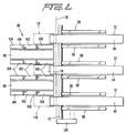
- Fig. 2 is a simplified plan view of the sheet feeder of Fig. 1.
- the transfer belts 88 can be seen interdisposed between the feed belts 32.
- the series of three vacuum boxes 100, 102, 103 can be seen alongside each transfer belt 88.
- the position of the gate 28 is shown by a broken line with the belts 88 completely downstream from the gate 28, but with the delivery ends of the feed belts 32 extending a short distance past and downstream of the gate 28.
- the board guide 118 is shown in broken lines as made up of three guide plates spaced to the sides of and between the transfer belts 88 and their associated vacuum boxes 100, 102, 104.
- the drive shaft 42 for the feed belts 32 is shown extending across the full width of the sheet feeder and connected at one end to an intermittent drive transmission 128.
- the transmission 128 accelerates the feed belts 32 from rest, operates them at a predetermined feed speed, and then decelerates them back to rest in a cycle for each sheet 14 fed from the stack 16.
- Long sheets are those greater than say 15 inches in the machine feed direction (note, short sheets are illustrated in Fig. 1).
- a pile of long sheets is placed in the stack 16 and the coupling 84 engaged for drivingly oscillating the rear lifter shaft 54.
- the feed belts 32 are stationary but with their upper flights 44 raised into contact with the bottom sheet by the lift bars 46 being in their fully raised position with both ends raised by keys 56, 58.
- the feed belts 32 then accelerate to machine speed carrying the bottom sheet 14 with them. This sheet reaches machine speed when its leading edge reaches the downstream end of the first vacuum boxes 100 of the transfer conveyor 86.
- the vacuum in any first box 100 has no effect on this sheet 14 until the sheet closes the vacuum box 100 because the box is vented to atmosphere in front of the sheet.
- the vacuum box is closed by the sheet, coupling of the sheet to the transfer belts 88 occurs, and at this point the fed sheet is travelling at the same speed as the transfer belts 88.
- the feed belts 32 still continue at machine speed and remain vacuum coupled via vacuum boxes 66 to the sheet.
- the sheet is now under feed control of both sets of belts 32 and 88 which at this point are moving at the same speed; this continues until the second vacuum boxes 102 are closed off as the leading edge of the sheet reaches the downstream end of the second vacuum boxes 102.
- the lift bars 146 descend, the feed belts 32 are withdrawn from the sheet being fed, and the feed belts 32 begin decelerating to zero velocity preparatory to advancing the next sheet in the stack.
- the sheet 14 being fed covers, and is vacuum coupled by, both the first and second vacuum boxes 100 and 102 - this providing about the same area of vacuum coupling as previously provided by the vacuum boxes 66 in the feed section. This situation continues until the sheet closes off the third vacuum boxes 104 at which time the sheet 14 is under the control of all three sets of vacuum boxes 100, 102 and 104.
- the sheet continues to be fed by the transfer belts 88 until it reaches the print cylinder 18/impression roll 20 and beyond, depending upon the length of the sheet.
- This sheet is uncoupled from the three vacuum boxes 100, 102, 104 in sequence as the trailing edge of the sheet passes downstream of the upstream end of the respective vacuum box so venting that box to atmosphere.
- this enables each sheet to be positively fed to a point beyond the nip of the print cylinder and impression roll - which is a "kiss" type contact with the sheet, and then a gradual and progressive change- over provided from sheet feed by the transfer conveyor 86 to sheet feed by the downstream machinery.
- the sheets illustrated in Fig. 1 are about 12 inches in sheet length in the direction of the arrow 22. Feeding of short sheets is similar to the above feeding of long sheets except for a few differences which will be described.
- the belt lift bars 46 are lowered when the leading edge of the sheet 14 being fed closes off the first transfer vacuum boxes 100, although the feed belts 32 continue at machine speed to the same point as for long sheets above. This is done to prevent the feed belts 32 from trying to feed the next sheet in the stack 16 (which could jam such next sheet into the gate 28) as the bottom sheet, in the process of being fed, clears the stack 16.
- the second cam of a two cam arrangement is employed to drop the lift bars 46 at this earlier point for short sheets.
- the sheet 14 is controlled by the feed belts 32 and the transfer belts 88 over the first vacuum box 100, both sets of belts running at machine speed.
- the feed belts 32 no longer engage the sheet.
- each first vacuum box 100 is not as long as the boxes 66 in the feed section, there is less drag on the sheet being fed when it is a short sheet. Additional force is exerted on the sheet 14 when the second vacuum boxes 102 are closed by the leading edge of the sheet 14.
- Fig. 3 illustrates a second embodiment which is essentially the same as the embodiment of Figs. 1 and 2, except the transfer conveyor is arranged to contact and feed the upper surface of each sheet, and the number of successive vacuum boxes in the transfer conveyor has been reduced from three to two. Only the differences between the two embodiments will be described.
- a plurality of transfer belts 288 are disposed side-by-side similarly to the transfer belts 88 in Fig. 2, but above the plane of the support surface 30 with the lower flight of each transfer belt 288 in the plane of sheet feeding.
- Each belt 288 is trained around forward and rear idler pulleys 289 and 291, and an upper drive pulley 290, all the drive pulleys being mounted on a common drive shaft 294 rotated in the direction of the arrow 292.
- the first and second transfer vacuum boxes are referenced 200 and 202, respectively, and their separate plenums (connected to separate vacuum sources) are referenced 210 and 212, respectively.
- the pairs of vacuum boxes 200, 202 are separated by a thin partition 206.
- the guide 218 is generally parallel to the sheet feed plane with an outwardly flared entrance end, and is adjustably spaced a short distance below the belts 288 to normally not contact sheets 14 being fed but to guide any warped sheets for gripping by the vacuum of vacuum boxes 200, 202.
- the upper surface dust cleaning nozzle 222 is disposed between the gate 28 and the rear idler pulley 291.
- the lower surface dust cleaning nozzle 224 is disposed below the forward idler pulley 289 immediately downstream of the board guide 218.
- the cleaning nozzles 222 and 224 are otherwise similarly constructed and operated as the nozzles 122 and 124 of Fig. 1.
- a short section Y of the next bottom sheet in the stack 16 that is engaged by the raised and driving feed belts 32 before the lift bars 46 descend, this occurring while a trailing section of the short sheet 14 being fed is passing under the gate 28.
- This section Y may be about two inches long. Such a section Y may also occur with the embodiment of Fig. 1.
- Fig. 4 illustrates a third embodiment which is exactly the same as the first embodiment of Figs. 1 and 2, except for the mechanism for and manner of lifting the feed belt lift bars 46.
- the plurality of side-by-side lift bars 46 are the same, as are the oscillatable shafts 52, 54 with attached arms 68, 70 pivotally connected at their lower, free ends to cross link 72.
- the disengageable coupling 84 of Fig. 1 is omitted, and the arm 70 is rigidly attached to the shaft 54 - as is the arm 68 to the shaft 52.
- the cross link 72 has, midway along its length, a transversely projecting pin 302 which extends horizontally at right angles to the link 72.
- This pin 302 slidably engages in a radial slot 302 in the free end of a pivotally oscillatable drive arm 306.
- a servo motor 308 drivable oscillates the arm 306 in a timed sequence determined by the control system shown in Fig. 5.
- Arcuate oscillation of the arm 306 by the servo motor drive shaft 310 effects longitudinal oscillation of the link 72; this effects simultaneous oscillation of the arms 68, 70 in parallel, which is turn causes simultaneous equal oscillation of the two shafts 52, 54 to lower and raise the bars 46 via the transverse keys 56, 58. During this movement, the bars 46 all remain horizontal.
- the bar 46 is shown in its raised position elevating the upper flight 44 of one of the belts 32 above the support surface 30 of the stack 16. Pivotal movement of the drive arm 306 counterclockwise in the direction of the arrow 312 lowers each lift bar 46 to drop the upper flights 44 below the support surface 30. Completion of pivotal oscillation of the drive arm 306 clockwise again raises the lift bars 46 and upper flights 44.
- Fig. 5 shows schematically the control system for oscillating the drive shaft 310 of the servo motor 308.
- the machine speed of the downstream machinery e.g. the speed of rotation of the print cylinder 18 and impression roll 30, is transmitted via a transducer T as an input signal y to an electronic signal conditioning unit 314.
- a register 316 has four rotatable thumb wheels 318 for inputting the length of the sheets being fed. This sheet length dialled into the register 316 produces another input signal x to the signal conditioning unit 314.
- the signal conditioning unit 314 produces an output signal z which is fed to a servo drive speed control unit 320 which in turn controls oscillation of the servo drive motor 308 to lower and raise the lift bars 46.
- the signal z is a function of the signals x and y.
- the servo motor 308 is biased to oscillate in a counterclockwise direction (in Fig. 4) through a fixed arc to lower the lift bars 46 and maintain them in their lowered position with the feed belts 32 inoperative to feed the lowermost sheet of the stack 16.
- the signal conditioning unit 314 tells the servo motor 308 to oscillate in a clockwise direction through a fixed length arcuate stroke to raise the lift bars from their lowered position to their upper position shown in Fig. 4; the duration of the signal corresponds to the sheet length dialled into register 316.
- the signal z is removed and the servo motor 308 reverses direction to lower the lift bars 46, the drive arm oscillating in the direction of the arrow 312 in Fig. 4.
- the signal y from the machine speed transducer T ensures that the timing of the oscillation strokes of the servo motor 308 matches changes in machine speed.
- the mechanism can be controlled so that the lift bars 46 lower when the leading edge of the sheet 14 has just covered the most downstream vacuum box, the three vacuum boxes 100, 102 and 104 then being in full control of the sheet 14. This should provide a smooth handoff between the feed belts 32 and the transfer belts 88. By lowering the lift bars 46 when the leading edge of the sheet 14 covers the third vacuum box 104, there is less opportunity for the feed belts 32 to begin acting on the next sheet.
- control system of Fig. 5 could also be used with the embodiments of Figs. 1 and 3.
- the last transfer vacuum box may be vented to the preceding vacuum box by small vent holes 299 in the partition between these vacuum boxes; for example, in Fig. 1 the partition 106 between the third and second vacuum boxes 104 and 102 may be provided with small vent holes 299. This would cause a slow bleed-down of the vacuum in the last downstream vacuum box as the immediately preceding vacuum box is uncovered by the trailing end of the sheet being fed and so vented to atmosphere. In this way, an even more gentler handoff of this sheet to the print cylinder/impression roll would be obtained.
- Fig. 6 is a plan view of the corrugated paperboard sheet 14 showing a leading crease or score line 338 and a parallel trailing crease line 340. There may be one or more additional crease lines between the creases 338, 340.
- the sheet is fed in the direction of the arrow 22, and the creases 338, 340 are at right angles to the feed direction 22.
- the cross links or segments 72 and their drive arrangements may be omitted and replaced by a servo motor on, or directly driving, each of the shafts 52, 54.
- the two servo motors would be the same as the servo motor 308 and both would be simultaneously controlled by the control system of Fig. 5.
- disconnectable coupling 84 of the Fig. 1 embodiment could be incorporated on shaft 54 in the Fig. 4 embodiment to optionally enable only the downstream portions of the lift bars 46 to be raised.
- Fig. 3 could have three vacuum boxes above the operative flight of the transfer belts 288 just as the embodiment of Fig. 4 has three vacuum boxes below the operative transfer flights.
- the above embodiments provide lead edge feeders with improved feeding of corrugated paperboard sheets, either eliminating any tendency for crushing of such sheets, or at least enabling such tendency for crushing to be reduced, and/or reducing any possibility of slippage while feeding the sheets.
Landscapes
- Engineering & Computer Science (AREA)
- Mechanical Engineering (AREA)
- Sheets, Magazines, And Separation Thereof (AREA)
- Making Paper Articles (AREA)
Description
- This invention relates to feeding sheets from a stack to downstream equipment. It particularly relates to feeding sheets of corrugated paperboard and to improving such feeding.
- In the paperboard industry, it is known to use lead edge sheet feeders for feeding sheets one at a time in timed sequence to downstream equipment, e.g. container blank processing machinery. Such lead edge feeders employ vacuum conveyors as, for example, disclosed in US Patent 4,494,745 and US Patent 4,867,433. These lead edge feeders include a pair of pull rolls for taking over feeding of each sheet from the initial vacuum conveyor and then feeding the sheet to the downstream equipment. Such pull rolls can have an adverse effect on the sheets gripped and fed therebetween.
- It has been proposed to replace these pull rolls by a second vacuum conveyor as disclosed in US Patents 3,941,372 and 4,236,708 to avoid damage to the sheets by the pressure of the pull rolls, e.g. crushing of corrugated paperboard sheets.
- German Patent Application DE-A-3 001 652 discloses a sheet feeding apparatus which comprises a single source of vacuum and three adjacent vacuum boxes separated by flaps. The single source of vacuum transfers the effective vacuum application area applied to the moving sheet by the use of the flaps between adjacent vacuum boxes.
- One aspect of the present invention is concerned with eliminating pull rolls from sheet feeders.
- Another aspect of the present invention is additionally, or independently, concerned with providing an arrangement which more gently completes the transfer of the feeding of the sheets to the downstream equipment.
- According to the present invention there is provided a sheet feeding apparatus, comprising:
a stack support surface for supporting a stack of sheets;
intermittently driven feed means for feeding the sheets one at a time from the stack through a control gate in a downstream direction;
a feed vacuum box associated with said feed means and having an open face communicating with a sheet while being fed by said feed means;
a source of vacuum connected to said feed vacuum box, and effective, in use, at said open face;
transfer conveyor means downstream of said control gate, for successively receiving each sheet from the feed means and then feeding each sheet downstream of the feeding apparatus; and
said transfer conveyor means comprising:
as continuously driven endless belt;
a first transfer vacuum box having an open face cooperative with an upstream portion of said endless belt; and
a second transfer vacuum box having an open face cooperative with a downstream portion of said endless belt; characterized by
means for separately connecting said first and second transfer vacuum boxes continuously, in use, to a supply of vacuum for providing continuous availability of vacuum at the open faces of said first and second transfer vacuum boxes; and
said upstream portion of said endless belt only being effective to grip the sheet being fed while this sheet is completely covering the open face of said first transfer vacuum box and said downstream portion of said endless belt only being effective to grip the sheet being fed while this sheet is completely covering the open face of said second transfer vacuum box. - Preferably, said transfer conveyor means further comprises:
a third transfer vacuum box having an open face cooperative with an extreme downstream portion of said endless belt, said extreme downstream portion being downstream of said downstream portion associated with said second transfer vacuum box;
means for continuously connecting, in use, said third transfer vacuum box to a supply of vacuum for providing continuous availability of vacuum at the open face of said third transfer vacuum box; and
said extreme downstream portion of said endless belt only being effective to grip the sheet being fed while this sheet is completely covering the open face of said third transfer vacuum box. - Advantageously, said apparatus includes vent means connecting said third transfer vacuum box, to said second vacuum transfer box, for venting said third transfer vacuum box to atmosphere via said second transfer vacuum box when the sheet being fed is completely covering the open face of said third transfer vacuum box but only partially covering the open face of said second transfer vacuum box.
- Preferably, said feed means is disposed essentially below said stack support surface and said continuously driven endless belt of said conveyor means is disposed above said stack support surface, said feed means engaging a lower surface of the sheet being fed and said continuously driven endless belt of said conveyor means engaging an upper surface of this sheet.
- Advantageously, said feed means includes a board guide spaced below said continuously driven endless belt of said conveyor means adjacent said first transfer vacuum box for diverting towards the open face of said first transfer vacuum box any warped sheet being fed by said feed means.
- Preferably, said apparatus includes a sheet upper surface dust cleaning nozzle disposed between said control gate and an upstream end of said endless belt, and a sheet lower surface dust cleaning nozzle, disposed below said endless belt downstream of said board guide.
- Advantageously, said intermittently driven feed means includes means for moving said feed means between an operative position and an inoperative position; and further comprising:
control means, capable of having information input thereinto, for controlling timing of movement of said feed means from the operative position to the inoperative position in dependence upon a linear dimension related to the sheets and input into said control means. - Preferably, said control means comprises an input register for the inputting of said linear dimension, an electronic signal conditioning unit and a servo drive, the input register providing a first signal to the electronic signal conditioning unit which in turn produces an output signal for operating the servo drive.
- Advantageously, said control means, includes a machine speed transducer (T) which provides a second signal to the electronic signal conditioning unit in dependence upon a rate at which sheets are to be fed, said output signal being a function of said first and second signals.
- For a better understanding of the present invention reference will now be made, by way of example, to the accompanying drawings, in which like reference characters in the same or different Figures indicate the parts and in which:
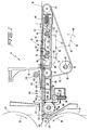
- FIG.1 is a simplified diagrammatic side elevation, partly in section, illustrating a sheet feeding apparatus according to the invention;
- FIG.2 is a diagrammatic plan view of the sheet feeding apparatus of Fig. 1 with parts omitted for simplicity and clarity;
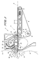
- FIG.3 is a view similar to Fig. 1 but of a second embodiment of a sheet feeding apparatus according to the invention;
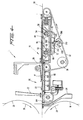
- FIG.4 is a view similar to Fig. 1 of a preferred modification of the sheet feeding apparatus of Fig. 1;
- FIG. 5 is a schematic of a control system according to the invention for lifting the feeding belts in the embodiment of Fig. 4;
- FIG. 6 is a plan view of a corrugated paperboard container blank having score lines.
- One preferred embodiment of the invention is illustrated in Figs. 1 and 2 and another in Fig. 3. A further embodiment of the invention is illustrated in Fig. 4 having the preferred feed belt lifting arrangement controlled by the control system of Fig. 5.
- All of these embodiments are
lead edge feeders feeding sheets 14 of corrugated paperboard, one by one from astack 16 of such sheets, to downstream processing equipment, such as one or more flexographic printing sections, a die cutting section, a slotter section, etc. In Figs. 1 3, 4 and 5,container blanks 14 are illustrated being fed in the direction of thearrow 22 to and through the kissing nip of aprinting cylinder 18 and a cooperatingimpression roll 20 which are rotatably driven in the direction of thearrows vertical gate 28 allows only one sheet at a time to be fed from the bottom of thestack 16. - Fig. 1 illustrates the
stack 16 supported on ahorizontal support surface 30. A plurality of parallel, endless feed belts 32 (see also Fig. 2) spaced apart across the width of the feeder are each trained over front andrear idler pulleys lower drive pulley 38. Thedrive pulleys 38 are intermittently rotatably driven in the direction of thearrow 40 by adrive shaft 42 on which they are keyed in axial spaced-apart relationship. Theupper flight 44 of eachfeed belt 32 passes over abar 46 disposed between each pair ofpulleys bar 46 has forward and rear downwardlyopen slots oscillatable shafts circular section key keys shaped seats slots shafts keys arrows 64 atkey 56, so causing eachbar 46 to be raised slightly above thesupport surface 30 or withdrawn a little below thissupport surface 30. When thebars 46 are in the raised position, theupper flights 44 of thebelts 32 frictionally engage the lowermost blank 14 in thestack 16 and feed this blank 14 forwardly below thegate 28. When thebars 46 are in their lower position, spaced below thesurface 30, thebelts 32 do not engage the lowermost blank 14 (or any blank already in the process of being fed to the print cylinder 24). Theshaft 42 is accelerated from rest, driven at a constant speed, and then decelerated to rest in timed relation to the raising and lowering of thebars 46; the raised position of thebars 46 providing an operative position of thefeed belts 32, and the lowered position of thebars 46 providing an inoperative position of thefeed belts 32. In this way, the lowermost blank in thestack 16 can be engaged by the friction surfacedbelts 32 while stationary, so that theupper flights 44 engage this blank with static friction therebetween. Thebelts 32 then accelerate this blank from rest to line speed, i.e. the surface speed of theprinting cylinder 18 and theimpression roll 20. Thebelts 32 can then be lowered out of contact with the blank being fed and decelerated to rest, theupper flight 44 of each belt remaining for a period at rest below thesupport surface 30. In this way each bottom sheet of thestack 16 can be successively fed under thegate 28 in timed relation to the downstream processing machinery, e.g. to register with the printing die of theprinting cylinder 18. - An upwardly
open vacuum box 66 extends along each side of eachupper flight 44, the upper edges of theboxes 66 forming part of thesupport surface 30. These vacuum boxes are connected to a common plenum extending across thesheet feeder 10 below thesupport surface 30, this common plenum being connected to a source of continuous vacuum so that vacuum is continuously applied at the upper edges of thevacuum boxes 66 to draw the lowermost blank of thestack 16 downwards thereagainst or towards. This continuous application of vacuum serves to flatten warped sheets and hold thesheet 14 being fed tightly against theupper flights 44 of thefeed belts 32. - The general construction and operation of the
feed belts 32, the raising and lowering of the lift bars 46, the transmission for intermittently driving theshaft 42, the application of vacuum, and the timing of these movements is described and illustrated in greater detail in US Patent 4,494,745, the disclosure of which is hereby incorporated herein by reference. This mechanism and its operation in feeding different length sheets is further described and modified in US Patent 4,867,433, the disclosure of which is also hereby incorporated herein by reference. - However, according to the present invention, the drive to the
lift shaft 54 may be disconnected and only the forward portion of eachlift bar 46 raised and lowered by the oscillation of theforward lift shaft 52, thebars 46 then pivoting on the disconnectedrear lift shaft 54 which, due to the key 58, pivots in unison with thebars 46. A radial arm (or a gear segment) 68, 70 is secured to eachlift shaft 53, 54. A cross link (or a gear segment) 72 pivotally connects the lower ends 74 of thearms lever 76 has one end pivotally attached at 78 to thecross link 72 and the other end oscillatable in the direction of thearrow 80 via a rotating cam or other suitable mechanism, the bell crank lever being pivotally mounted at 82. Thearm 68 is rigidly connected to thelift shaft 52, but thearm 70 is connected to therear lift shaft 54 via adisengageable coupling 84. Thecoupling 84 can be engaged or disengaged via a solenoid to cause thearm 70 to drivingly oscillate theshaft 54 or pivot relative to theshaft 54. For feeding long sheets, thecoupling 84 is connected so that the whole of eachbar 46 raises and lowers relative to thesupport surface 30 with the bar remaining parallel thereto. For feeding short sheets, as illustrated, thecoupling 84 is disconnected so that eachbar 46 pivots onrear shaft 54 with only the forward portion of eachlift bar 46 raising above thesupport surface 30; this minimizes the feedingflights 44 of thebelts 32 interfering with the next bottom sheet of thestack 16 while still feeding thebottom sheet 14. - Between the
gate 28 and theprinting cylinder 18 is atransfer conveyor 86 comprising a plurality of parallel endless belts 88 (see also Fig. 2) each trained over a forward drivenpulley 90 and a rearidler pulley 34. The upper flight of eachtransfer belt 88 is in the plane of thesupport surface 30 with the rest of thetransfer conveyor 86 being below. The forward pulleys 90 are continuously driven in the direction of thearrow 92 by adrive shaft 94 to continuously drive thebelts 88 at the line speed of the downstream machinery. The rear idler pulleys 34 are the same as, coaxial with, but interdisposed between the forward idler pulleys 34 of thefeed belts 32. A tensioningpulley 96 is biased upwardly by aspring 98 against the lower flight of eachtransfer belt 88. Threeadjacent vacuum boxes vertical partitions 106. Eachvacuum box separate vacuum plenum first vacuum boxes 100 being connected to thesame plenum 110 which extends transversely across thetransfer conveyor 86 between the upper and lower flights of thetransfer belts 88. All the second vacuum boxes are similarly connected to thesingle plenum 112 likewise extending transversely across the transfer conveyor alongside theplenum 110. All thethird vacuum boxes 104 are connected byshort pipes 116 to the single plenum 114 disposed below the lower flight of thetransfer belts 88 directly below theplenum 112. Eachplenum - A
sheet 14 being fed from the bottom of thestack 16, progressively passes over the row offirst vacuum boxes 100, then the row ofsecond vacuum boxes 102, and then the row ofthird vacuum boxes 104. Vacuum is continuously connected to all thevacuum boxes sheet 14 firmly against, and into driven frictional contact with, the continuously driventransfer belts 88 which are always being driven at the machine speed of the downstream machinery. However, as the tops of thevacuum boxes sheet 14 against thebelts 88 until that vacuum box is completely covered by the advancingsheet 14. That is, until any particular vacuum box is fully covered by the advancing sheet, atmospheric air is drawn into the vacuum box by the source of vacuum connected thereto, so applying insufficient reduced air pressure to the underside of the advancing sheet to draw it firmly towards the vacuum box and against thebelts 88. - Thus, as the leading edge of an advancing
sheet 14 passes under thegate 28 and over thefirst vacuum boxes 100, this sheet is not drawn into firm frictional engagement with the movingbelts 88 until the sheet's leading edge reaches thepartitions 106 between the first andsecond boxes first vacuum box 100. Similarly, thesecond vacuum boxes 102 have no effect until the leading edge of the advancing sheet reaches thepartitions 106 between the second andthird vacuum boxes third vacuum boxes 104 are similarly effective in drawing the advancingsheet 14 against thetransfer belts 14 only after the leading edge of thesheet 14 has reached the downstream end of theboxes 104 to completely cover the tops of theboxes 104. - An
adjustable board guide 118 is disposed above the level of the upper flight of thetransfer belts 88 and is mounted on anadjustable shaft 120 just downstream from thegate 28. Adjustable rotation of theshaft 120 through a few degrees spaces theguide 118 from and above the plane of the support surface 30 a distance depending upon the thickness of the sheets being processed. The guide is adjusted so that it normally will not touch an advancingsheet 14 other than to force down a warped leading edge so that the vacuum can be effective to pull the warped sheet down against thetransfer belts 88. Theguide 18 forms a downwardly inclined ramp for such warped sheets and extends the full length of thefirst vacuum box 100. - An upperside
dust cleaning nozzle 122 is disposed just a short distance above the plane of the advancingsheets 14 at a location over thethird vacuum box 104. A lowersidedust cleaning nozzle 124 is disposed directly below the plane of the advancingsheets 14 at a location between the downstream end of thethird vacuum box 104 and the nip of theprinting cylinder 18 with theimpression roll 20. Both cleaningnozzles transfer conveyor 86 and are connected to a source of vacuum. Each cleaningnozzle like foot 126 which extends in a plane parallel to, and in closed proximity to, eachsheet 14 as it advances to theprinting cylinder 18 to clean dust etc. from both sides of the advancing sheet. - Fig. 2 is a simplified plan view of the sheet feeder of Fig. 1. The
transfer belts 88 can be seen interdisposed between thefeed belts 32. The series of threevacuum boxes transfer belt 88. The position of thegate 28 is shown by a broken line with thebelts 88 completely downstream from thegate 28, but with the delivery ends of thefeed belts 32 extending a short distance past and downstream of thegate 28. Theboard guide 118 is shown in broken lines as made up of three guide plates spaced to the sides of and between thetransfer belts 88 and their associatedvacuum boxes drive shaft 42 for thefeed belts 32 is shown extending across the full width of the sheet feeder and connected at one end to anintermittent drive transmission 128. Thetransmission 128 accelerates thefeed belts 32 from rest, operates them at a predetermined feed speed, and then decelerates them back to rest in a cycle for eachsheet 14 fed from thestack 16. - Operation of the sheet feeder for long sheets will now be described. Long sheets are those greater than say 15 inches in the machine feed direction (note, short sheets are illustrated in Fig. 1). A pile of long sheets is placed in the
stack 16 and thecoupling 84 engaged for drivingly oscillating therear lifter shaft 54. At the beginning of feed, thefeed belts 32 are stationary but with theirupper flights 44 raised into contact with the bottom sheet by the lift bars 46 being in their fully raised position with both ends raised bykeys feed belts 32 then accelerate to machine speed carrying thebottom sheet 14 with them. This sheet reaches machine speed when its leading edge reaches the downstream end of thefirst vacuum boxes 100 of thetransfer conveyor 86. As previously mentioned, the vacuum in anyfirst box 100 has no effect on thissheet 14 until the sheet closes thevacuum box 100 because the box is vented to atmosphere in front of the sheet. When the vacuum box is closed by the sheet, coupling of the sheet to thetransfer belts 88 occurs, and at this point the fed sheet is travelling at the same speed as thetransfer belts 88. Thefeed belts 32 still continue at machine speed and remain vacuum coupled viavacuum boxes 66 to the sheet. Thus, the sheet is now under feed control of both sets ofbelts second vacuum boxes 102 are closed off as the leading edge of the sheet reaches the downstream end of thesecond vacuum boxes 102. At this point, the lift bars 146 descend, thefeed belts 32 are withdrawn from the sheet being fed, and thefeed belts 32 begin decelerating to zero velocity preparatory to advancing the next sheet in the stack. At this point, thesheet 14 being fed covers, and is vacuum coupled by, both the first andsecond vacuum boxes 100 and 102 - this providing about the same area of vacuum coupling as previously provided by thevacuum boxes 66 in the feed section. This situation continues until the sheet closes off thethird vacuum boxes 104 at which time thesheet 14 is under the control of all three sets ofvacuum boxes transfer belts 88 until it reaches theprint cylinder 18/impression roll 20 and beyond, depending upon the length of the sheet. This sheet is uncoupled from the threevacuum boxes transfer conveyor 86 to sheet feed by the downstream machinery. - Operation of the sheet feeder for short sheets, say less than 15 inches, will now be described. The sheets illustrated in Fig. 1 are about 12 inches in sheet length in the direction of the
arrow 22. Feeding of short sheets is similar to the above feeding of long sheets except for a few differences which will be described. The belt lift bars 46 are lowered when the leading edge of thesheet 14 being fed closes off the firsttransfer vacuum boxes 100, although thefeed belts 32 continue at machine speed to the same point as for long sheets above. This is done to prevent thefeed belts 32 from trying to feed the next sheet in the stack 16 (which could jam such next sheet into the gate 28) as the bottom sheet, in the process of being fed, clears thestack 16. The second cam of a two cam arrangement, similar to that in the dual feed cam arrangement disclosed and shown in the above referenced US Patent 4,867,433, is employed to drop the lift bars 46 at this earlier point for short sheets. Thus, thesheet 14 is controlled by thefeed belts 32 and thetransfer belts 88 over thefirst vacuum box 100, both sets of belts running at machine speed. However, as thesheet 14 advances over thesecond vacuum box 102, thefeed belts 32 no longer engage the sheet. Even though eachfirst vacuum box 100 is not as long as theboxes 66 in the feed section, there is less drag on the sheet being fed when it is a short sheet. Additional force is exerted on thesheet 14 when thesecond vacuum boxes 102 are closed by the leading edge of thesheet 14. Still additional force is exerted when thethird vacuum boxes 104 are closed, but just thereafter the trailing edge of thesheet 14 vents thefirst vacuum boxes 100 to atmosphere. By the time the trailing edge vents thethird vacuum boxes 104 to atmosphere, the leading edge of the sheet has passed through the nip of the print cylinder/impression roll and is under the control thereof. As mentioned Previously, the feed belt lift bars 46 are pivoted about theupstream lift shaft 54 for short sheet feeding, thecoupling 84 being disengaged to effect this. This is done so that the full length of thelift bar 46 does not effect feed belt engagement with the next sheet too soon, as it might if the full length of thelift bar 46 was active. Tests have indicated that less than full length lift bar engagement by thefeed belts 32 is sufficient for the feeding of short sheets. - Fig. 3 illustrates a second embodiment which is essentially the same as the embodiment of Figs. 1 and 2, except the transfer conveyor is arranged to contact and feed the upper surface of each sheet, and the number of successive vacuum boxes in the transfer conveyor has been reduced from three to two. Only the differences between the two embodiments will be described. A plurality of
transfer belts 288 are disposed side-by-side similarly to thetransfer belts 88 in Fig. 2, but above the plane of thesupport surface 30 with the lower flight of eachtransfer belt 288 in the plane of sheet feeding. Eachbelt 288 is trained around forward and rear idler pulleys 289 and 291, and anupper drive pulley 290, all the drive pulleys being mounted on acommon drive shaft 294 rotated in the direction of thearrow 292. The first and second transfer vacuum boxes are referenced 200 and 202, respectively, and their separate plenums (connected to separate vacuum sources) are referenced 210 and 212, respectively. The pairs ofvacuum boxes thin partition 206. On the opposite side of the sheet feed plane to thetransfer belts 288 is aboard guide 218. Theguide 218 is generally parallel to the sheet feed plane with an outwardly flared entrance end, and is adjustably spaced a short distance below thebelts 288 to normally notcontact sheets 14 being fed but to guide any warped sheets for gripping by the vacuum ofvacuum boxes dust cleaning nozzle 222 is disposed between thegate 28 and the rearidler pulley 291. Whereas the lower surfacedust cleaning nozzle 224 is disposed below the forwardidler pulley 289 immediately downstream of theboard guide 218. The cleaningnozzles nozzles - The operation of this Fig. 3 embodiment with both long sheets and short sheets is similar to that described above for the embodiment of Figs. 1 and 2, except a third transfer vacuum box is not used.
- When feeding short sheets as shown in Fig. 3, there may be a short section Y of the next bottom sheet in the
stack 16 that is engaged by the raised and drivingfeed belts 32 before the lift bars 46 descend, this occurring while a trailing section of theshort sheet 14 being fed is passing under thegate 28. This section Y may be about two inches long. Such a section Y may also occur with the embodiment of Fig. 1. - Fig. 4 illustrates a third embodiment which is exactly the same as the first embodiment of Figs. 1 and 2, except for the mechanism for and manner of lifting the feed belt lift bars 46. The plurality of side-by-side lift bars 46 are the same, as are the
oscillatable shafts arms link 72. However, thedisengageable coupling 84 of Fig. 1 is omitted, and thearm 70 is rigidly attached to the shaft 54 - as is thearm 68 to theshaft 52. Thecross link 72 has, midway along its length, a transversely projectingpin 302 which extends horizontally at right angles to thelink 72. Thispin 302 slidably engages in aradial slot 302 in the free end of a pivotallyoscillatable drive arm 306. Aservo motor 308 drivable oscillates thearm 306 in a timed sequence determined by the control system shown in Fig. 5. Arcuate oscillation of thearm 306 by the servomotor drive shaft 310 effects longitudinal oscillation of thelink 72; this effects simultaneous oscillation of thearms shafts bars 46 via thetransverse keys bars 46 all remain horizontal. In Fig. 4, thebar 46 is shown in its raised position elevating theupper flight 44 of one of thebelts 32 above thesupport surface 30 of thestack 16. Pivotal movement of thedrive arm 306 counterclockwise in the direction of thearrow 312 lowers eachlift bar 46 to drop theupper flights 44 below thesupport surface 30. Completion of pivotal oscillation of thedrive arm 306 clockwise again raises the lift bars 46 andupper flights 44. - Fig. 5 shows schematically the control system for oscillating the
drive shaft 310 of theservo motor 308. The machine speed of the downstream machinery, e.g. the speed of rotation of theprint cylinder 18 andimpression roll 30, is transmitted via a transducer T as an input signal y to an electronicsignal conditioning unit 314. Aregister 316 has fourrotatable thumb wheels 318 for inputting the length of the sheets being fed. This sheet length dialled into theregister 316 produces another input signal x to thesignal conditioning unit 314. Thesignal conditioning unit 314 produces an output signal z which is fed to a servo drivespeed control unit 320 which in turn controls oscillation of theservo drive motor 308 to lower and raise the lift bars 46. The signal z is a function of the signals x and y. Theservo motor 308 is biased to oscillate in a counterclockwise direction (in Fig. 4) through a fixed arc to lower the lift bars 46 and maintain them in their lowered position with thefeed belts 32 inoperative to feed the lowermost sheet of thestack 16. Thesignal conditioning unit 314 tells theservo motor 308 to oscillate in a clockwise direction through a fixed length arcuate stroke to raise the lift bars from their lowered position to their upper position shown in Fig. 4; the duration of the signal corresponds to the sheet length dialled intoregister 316. As the leading edge of thesheet 14 being fed nears the end of thethird vacuum box 104, the signal z is removed and theservo motor 308 reverses direction to lower the lift bars 46, the drive arm oscillating in the direction of thearrow 312 in Fig. 4. The signal y from the machine speed transducer T ensures that the timing of the oscillation strokes of theservo motor 308 matches changes in machine speed. With the arrangement of Fig. 4, the lift bars 46 remain horizontal as they ascend and descend. - Thus, it will be appreciated that the mechanism can be controlled so that the lift bars 46 lower when the leading edge of the
sheet 14 has just covered the most downstream vacuum box, the threevacuum boxes sheet 14. This should provide a smooth handoff between thefeed belts 32 and thetransfer belts 88. By lowering the lift bars 46 when the leading edge of thesheet 14 covers thethird vacuum box 104, there is less opportunity for thefeed belts 32 to begin acting on the next sheet. - The control system of Fig. 5 could also be used with the embodiments of Figs. 1 and 3.
- In the above embodiments, the last transfer vacuum box may be vented to the preceding vacuum box by small vent holes 299 in the partition between these vacuum boxes; for example, in Fig. 1 the
partition 106 between the third andsecond vacuum boxes - Fig. 6 is a plan view of the
corrugated paperboard sheet 14 showing a leading crease or scoreline 338 and a paralleltrailing crease line 340. There may be one or more additional crease lines between thecreases arrow 22, and thecreases feed direction 22. - The above described embodiments, of course, are not to be construed as limiting the breadth of the present invention. Modifications, and other alternative constructions, will be apparent which are within the scope of the invention as defined in the appended claims.
- For example, in all the foregoing embodiments, the cross links or
segments 72 and their drive arrangements may be omitted and replaced by a servo motor on, or directly driving, each of theshafts servo motor 308 and both would be simultaneously controlled by the control system of Fig. 5. - Also, the
disconnectable coupling 84 of the Fig. 1 embodiment could be incorporated onshaft 54 in the Fig. 4 embodiment to optionally enable only the downstream portions of the lift bars 46 to be raised. - Further, the embodiment of Fig. 3 could have three vacuum boxes above the operative flight of the
transfer belts 288 just as the embodiment of Fig. 4 has three vacuum boxes below the operative transfer flights. - It will be appreciated that the above embodiments provide lead edge feeders with improved feeding of corrugated paperboard sheets, either eliminating any tendency for crushing of such sheets, or at least enabling such tendency for crushing to be reduced, and/or reducing any possibility of slippage while feeding the sheets.
Claims (9)
- A sheet feeding apparatus, comprising:
a stack support surface (30) for supporting a stack (16) of sheets;
intermittently driven feed means (32) for feeding the sheets one at a time from the stack through a control gate (28) in a downstream direction (22);
a feed vacuum box (66) associated with said feed means and having an open face communicating with a sheet (14) while being fed by said feed means (32);
a source of vacuum connected to said feed vacuum box (66), and effective, in use, at said open face;
transfer conveyor means (86) downstream of said control gate (28) for successively receiving each sheet from the feed means (32) and then feeding each sheet (14) downstream of the feeding apparatus; and
said transfer conveyor means (86) comprising:
a continuously driven endless belt (88 ; 288);
a first transfer vacuum box (100) having an open face cooperative with an upstream portion of said endless belt (88); and
a second transfer vacuum box (102) having an open face cooperative with a downstream portion of said endless belt (88); characterized by
means (110, 112) for separately connecting said first and second transfer vacuum boxes (100, 102) continuously, in use, to a supply of vacuum for providing continuous availability of vacuum at the open faces of said first and second transfer vacuum boxes (100, 102); and
said upstream portion of said endless belt (88) only being effective to grip the sheet (14) being fed while this sheet (14) is completely covering the open face of said first transfer vacuum box (100) and said downstream portion of said endless belt (88) only being effective to grip the sheet being fed while this sheet is completely covering the open face of said second transfer vacuum box (102). - The apparatus of Claim 1, wherein said transfer conveyor means (86) further comprises:
a third transfer vacuum box (104) having an open face cooperative with an extreme downstream portion of said endless belt (88), said extreme downstream portion being downstream of said downstream portion associated with said second transfer vacuum box (102);
means (112, 114) for continuously connecting, in use, said third transfer vacuum box (104) to a supply of vacuum for providing continuous availability of vacuum at the open face of said third transfer vacuum box (104); and
said extreme downstream portion of said endless belt (88) only being effective to grip the sheet (14) being fed while this sheet (14) is completely covering the open face of said third transfer vacuum box (104). - The apparatus of Claim 2, including vent means (106), connecting said third transfer vacuum box (104), to said second vacuum transfer box (102), for venting said third transfer vacuum box (104) to atmosphere via said second transfer vacuum box (102) when the sheet being fed is completely covering the open face of said third transfer vacuum box (104) but only partially covering the open face of said second transfer vacuum box (102).
- The apparatus of Claims 1, 2 or 3, wherein said feed means (32) is disposed essentially below said stack support surface (30) and said continuously driven endless belt (288) of said conveyor means is disposed above said stack support surface (30), said feed means (32) engaging a lower surface of the sheet being fed (14) and said continuously driven endless belt (288) of said conveyor means engaging an upper surface of this sheet (14).
- The apparatus of Claim 4, including a board guide (218) spaced below said continuously driven belt (288) of said conveyor means adjacent said first transfer vacuum box (200) for diverting towards the open face of said first transfer vacuum box (200) any warped sheet being fed by said feed means.
- The apparatus of any preceding Claim including a sheet upper surface dust cleaning nozzle (122; 222) disposed between said control gate (28) and an upstream end of said endless belt (88; 288), and a sheet lower surface dust cleaning nozzle (124; 224) disposed below said endless belt downstream of said board guide (118; 218).
- The apparatus of any preceding Claim wherein said intermittently driven feed means (32) includes means (308) for moving said feed means (32) between an operative position and an inoperative position; and further comprising:
control means (314), capable of having information input thereinto, for controlling timing of movement of said feed means (32) from the operative position to the inoperative position in dependence upon a linear dimension related to the sheets and input into said control means (314). - The apparatus of Claim 7, wherein said control means (314) comprises an input register for the inputting of said linear dimension, an electronic signal conditioning unit (314) and a servo drive (308), the input register providing a first signal to the electronic signal conditioning unit (314) which in turn produces an output signal for operating the servo drive (308).
- The apparatus of Claim 7 or 8, wherein said control means (314) includes a machine speed transducer (T) which provides a second signal to the electronic signal conditioning unit (314) in dependence upon a rate at which sheets are to be fed, said output signal being a function of said first and second signals.
Applications Claiming Priority (2)
| Application Number | Priority Date | Filing Date | Title |
|---|---|---|---|
| US580847 | 1990-09-11 | ||
| US07/580,847 US5074539A (en) | 1990-09-11 | 1990-09-11 | Feeding sheets of corrugated paperboard |
Publications (2)
| Publication Number | Publication Date |
|---|---|
| EP0479417A1 EP0479417A1 (en) | 1992-04-08 |
| EP0479417B1 true EP0479417B1 (en) | 1995-06-21 |
Family
ID=24322816
Family Applications (1)
| Application Number | Title | Priority Date | Filing Date |
|---|---|---|---|
| EP91306650A Expired - Lifetime EP0479417B1 (en) | 1990-09-11 | 1991-07-22 | Apparatus for feeding sheets of corrugated paperboard |
Country Status (4)
| Country | Link |
|---|---|
| US (1) | US5074539A (en) |
| EP (1) | EP0479417B1 (en) |
| JP (1) | JPH06227691A (en) |
| DE (1) | DE69110606T2 (en) |
Families Citing this family (70)
| Publication number | Priority date | Publication date | Assignee | Title |
|---|---|---|---|---|
| DE9111326U1 (en) * | 1991-09-12 | 1992-01-02 | Mathias Bäuerle GmbH, 7742 St Georgen | Friction feeder for paper sheets |
| US5383392A (en) * | 1993-03-16 | 1995-01-24 | Ward Holding Company, Inc. | Sheet registration control |
| US5606913A (en) * | 1993-03-16 | 1997-03-04 | Ward Holding Company | Sheet registration control |
| EP0623432B1 (en) * | 1993-04-08 | 1998-05-20 | Eastman Kodak Company | Apparatus for transporting and perforating elongated strips of material |
| US5509352A (en) * | 1994-09-23 | 1996-04-23 | Ward Holding Company | Paperboard processing machine with vacuum transfer system |
| US6059705A (en) * | 1997-10-17 | 2000-05-09 | United Container Machinery, Inc. | Method and apparatus for registering processing heads |
| JPH11314785A (en) * | 1998-05-07 | 1999-11-16 | Mitsubishi Heavy Ind Ltd | Paper feeder for corrugated sheet |
| DE19821871A1 (en) * | 1998-05-15 | 1999-11-18 | Giesecke & Devrient Gmbh | Bank note counting machine with tray advancing towards counter |
| EP0989082B1 (en) * | 1998-09-08 | 2002-03-06 | Asahi Seiko Kabushiki Kaisha | Apparatus for dispensing notes |
| US6164432A (en) * | 1998-11-17 | 2000-12-26 | Roberts Polypro, Inc. | Apparatus for feeding articles |
| GB9915989D0 (en) * | 1999-07-09 | 1999-09-08 | Sullivan John A | Machine combination |
| US7594912B2 (en) | 2004-09-30 | 2009-09-29 | Intuitive Surgical, Inc. | Offset remote center manipulator for robotic surgery |
| US6418847B1 (en) | 1999-10-20 | 2002-07-16 | Ward Holding Company | Printing machine with plate thickness compensation |
| US6511062B1 (en) | 2000-02-07 | 2003-01-28 | Lockheed Martin Corporation | Presentation control for flat article singulation mechanism and sensors suitable for use therewith |
| DE20002818U1 (en) * | 2000-02-16 | 2001-06-28 | Kohmann GmbH & Co.KG Maschinenbau, 40822 Mettmann | Belt cycle investors |
| SE0002818L (en) * | 2000-08-03 | 2001-08-20 | Emba Machinery Ab | Method and apparatus for feeding a sheet at a time from a sheet stack |
| US6662929B1 (en) | 2000-11-17 | 2003-12-16 | Lockhead Martin Corporation | Parcel singulation software control logic |
| US6575450B2 (en) * | 2001-01-30 | 2003-06-10 | Lockheed Martin Corporation | Singulation mechanism |
| US20030000871A1 (en) * | 2001-07-02 | 2003-01-02 | Fitzgibbons Patrick J. | Sorting system |
| US6711462B2 (en) * | 2002-03-05 | 2004-03-23 | Lockheed Martin Corporation | System and method for collating items |
| US6924451B2 (en) * | 2002-10-08 | 2005-08-02 | Lockheed Martin Corporation | Method for sequentially ordering objects using a single pass delivery point process |
| US20040251179A1 (en) * | 2002-10-08 | 2004-12-16 | Hanson Bruce H. | Method and system for sequentially ordering objects using a single pass delivery point process |
| US7250582B2 (en) * | 2002-10-08 | 2007-07-31 | Lockheed Martin Corporation | Method and system for sequentially ordering objects using a single pass delivery point process |
| US7819790B2 (en) * | 2004-02-20 | 2010-10-26 | Dixie Consumer Products Llc | Apparatus for making paperboard pressware with controlled blank feed |
| FI118017B (en) * | 2004-03-11 | 2007-05-31 | Metso Paper Inc | Suppressor belt conveyor for inserting a conveyor belt into a forming machine |
| US7671293B2 (en) * | 2004-09-08 | 2010-03-02 | Lockheed Martin Corporation | System and method for dynamic allocation for bin assignment |
| US10646292B2 (en) | 2004-09-30 | 2020-05-12 | Intuitive Surgical Operations, Inc. | Electro-mechanical strap stack in robotic arms |
| US9261172B2 (en) * | 2004-09-30 | 2016-02-16 | Intuitive Surgical Operations, Inc. | Multi-ply strap drive trains for surgical robotic arms |
| US8269125B2 (en) * | 2005-06-02 | 2012-09-18 | Lockheed Martin Corporation | Mixed product delivery point sequencer and method of use |
| US7419462B1 (en) | 2005-06-13 | 2008-09-02 | Dixie Consumer Products Llc | Pressware die set with pneumatic blank feed |
| JP4549238B2 (en) * | 2005-06-14 | 2010-09-22 | デュプロ精工株式会社 | Paper feeder |
| US20070090028A1 (en) * | 2005-10-25 | 2007-04-26 | Lockheed Martin Corporation | Sort mechanism and method of use |
| US7635124B2 (en) * | 2005-12-28 | 2009-12-22 | Sun Automation, Inc. | Feeder with adjustable time cycle and method |
| KR100990297B1 (en) * | 2005-12-30 | 2010-10-26 | 노틸러스효성 주식회사 | Front drive plate and transfer plate linkage driving device |
| DE102006005676A1 (en) * | 2006-01-30 | 2007-08-09 | Wilhelm Bahmüller, Maschinenbau Präzisionswerkzeuge GmbH | Cut carton box sections separating device, has first belt driven directly by controlled drive to convey sections from stacked material |
| DE102007017056A1 (en) * | 2006-05-04 | 2007-11-08 | Heidelberger Druckmaschinen Ag | Non-integer bulk feeder for substrates processing machines |
| KR100902983B1 (en) * | 2006-05-11 | 2009-06-15 | 가부시끼가이샤 도시바 | Paper sheet separating and take-out device |
| US20080157461A1 (en) * | 2006-10-03 | 2008-07-03 | Roth Curtis A | Sheet feed method and apparatus |
| DE102006061399B4 (en) * | 2006-12-23 | 2023-06-22 | Koenig & Bauer Ag | Method of feeding a shingled arc stream |
| DE102006061429B4 (en) * | 2006-12-23 | 2023-07-20 | Koenig & Bauer Ag | Method of feeding a shingled arc stream |
| DE102007039259B3 (en) * | 2007-08-20 | 2008-12-04 | CPS-Engineering Müller & Glaser Ing.-Partner | Feeding device and method for feeding sheets from a stack |
| JP4950812B2 (en) * | 2007-08-29 | 2012-06-13 | 株式会社東芝 | Paper sheet take-out device |
| US7766318B2 (en) * | 2008-08-05 | 2010-08-03 | Siemens Industry, Inc. | Pickoff mechanism for mail feeder |
| CN101935959B (en) * | 2010-08-09 | 2012-12-05 | 青岛美光机械有限公司 | Servo side pressing and paper feeding machine |
| DE102012013517A1 (en) * | 2012-07-06 | 2014-01-09 | Giesecke & Devrient Gmbh | Device and method for separating value documents, as well as value document processing system |
| WO2016001786A1 (en) * | 2014-07-02 | 2016-01-07 | Rotoprint Sovrastampa S.R.L. | System and method for overprinting on packages and/or containers of different formats |
| JP6106644B2 (en) * | 2014-08-29 | 2017-04-05 | 昌弘 塚崎 | Paper feeder |
| US9162834B1 (en) * | 2014-11-12 | 2015-10-20 | Jun-Yen Lee | Front-edge paper feeding device |
| JP6270050B2 (en) * | 2014-11-18 | 2018-01-31 | 三菱重工機械システム株式会社 | Sheet feeding device |
| US9522798B2 (en) | 2015-04-30 | 2016-12-20 | Theodore Michael Baum | Corrugated paperboard box converting machine retrofit for eliminating edge crush test degradation |
| TWI651211B (en) * | 2015-08-26 | 2019-02-21 | 塚崎昌弘 | Paper feeding device |
| ES2642941B1 (en) * | 2016-05-18 | 2018-09-11 | Comercial Industrial Maquinaria Carton Ondulado, S.L. | INTRODUCTIVE SET FOR THE SUPPLY OF LAMINARY ELEMENTS IN A GRAPHIC PRINTING STATION |
| US10766278B2 (en) | 2017-01-23 | 2020-09-08 | Koenig & Bauer Ag | Printing press |
| CN110325374B (en) | 2017-01-23 | 2021-07-09 | 柯尼格及包尔公开股份有限公司 | Method for operating a sheet-fed processing machine and sheet-fed processing machine |
| JP6805016B2 (en) | 2017-02-10 | 2020-12-23 | 三菱重工機械システム株式会社 | Corrugated cardboard sheet feeding device and box making machine |
| DE102017202922B4 (en) | 2017-02-23 | 2019-10-10 | Koenig & Bauer Ag | Suction belt table of a sheet feeder with at least one suction belt |
| GB201712829D0 (en) * | 2017-08-10 | 2017-09-27 | Wade Colin Maxwell | Vacuum Lifter |
| DE102017220594A1 (en) | 2017-11-17 | 2019-05-23 | Koenig & Bauer Ag | Method for operating a sheet processing machine |
| DE102017222314B4 (en) | 2017-12-08 | 2023-05-04 | Koenig & Bauer Ag | substrate feeder |
| DE102017222315B4 (en) | 2017-12-08 | 2020-11-05 | Koenig & Bauer Ag | Substrate feeding device |
| DE102017222316A1 (en) | 2017-12-08 | 2019-06-13 | Koenig & Bauer Ag | Substrate supply means |
| DE102018204314A1 (en) | 2018-03-21 | 2019-09-26 | Koenig & Bauer Ag | Sheet processing machine with smoothing device and a method for processing arcuate substrate |
| DE102018204319A1 (en) | 2018-03-21 | 2019-09-26 | Koenig & Bauer Ag | Sheet processing machine with side suction |
| IT201800007630A1 (en) * | 2018-07-30 | 2020-01-30 | Fives Intralogistics Spa Con Socio Unico | Singularizing apparatus. |
| CN109292488B (en) * | 2018-10-18 | 2019-10-11 | 广州科盛隆纸箱包装机械有限公司 | The more specification cardboards transmission paper feeder and paper feeding method of corrugated paper box printing machine |
| ES1237244Y (en) * | 2019-09-16 | 2020-02-04 | Comercial Industrial Maqu Carton Ondulado S L | Tank assembly of an introducer assembly for the supply of continuous laminar elements and an introducer assembly |
| JP7433021B2 (en) * | 2019-11-08 | 2024-02-19 | 三菱重工機械システム株式会社 | Paper feeding device and box making machine |
| CN115636278B (en) * | 2022-10-31 | 2024-03-26 | 北京永创通达机械设备有限公司 | Paper separating and feeding device of film packaging machine |
| EP4538207A1 (en) | 2023-10-13 | 2025-04-16 | Bobst Mex Sa | Feeder module |
| EP4538209A1 (en) * | 2023-10-13 | 2025-04-16 | Bobst Mex Sa | Feeder with moving belt |
Family Cites Families (22)
| Publication number | Priority date | Publication date | Assignee | Title |
|---|---|---|---|---|
| US1926306A (en) * | 1932-02-04 | 1933-09-12 | Goodrich Co B F | Apparatus for removing foreign matter from alpha traveling sheet of material |
| US2152027A (en) * | 1937-07-26 | 1939-03-28 | Carll Harry | Suction cleaner for bag printing machines |
| US3193282A (en) * | 1963-03-13 | 1965-07-06 | Koppers Co Inc | Mechanism for feeding cardboard or like blanks |
| US3198514A (en) * | 1963-05-10 | 1965-08-03 | Gen Electric | Document feeding system |
| DE1177174B (en) * | 1963-06-24 | 1964-09-03 | Standard Elektrik Lorenz Ag | Arrangement for the separation and removal of individual flat documents from a stack of documents |
| US3260520A (en) * | 1964-03-09 | 1966-07-12 | Gen Electric | Document handling apparatus |
| US3424453A (en) * | 1965-08-30 | 1969-01-28 | Mohawk Data Sciences Corp | Card picker mechanism |
| US3405935A (en) * | 1966-12-30 | 1968-10-15 | Soroban Engineering Inc | Card picker mechanism |
| FR2011540A1 (en) * | 1968-06-24 | 1970-03-06 | Bobst Fils Sa J | |
| DE1817101B2 (en) * | 1968-12-27 | 1972-04-13 | Telefunken Patentverwertungsgesellschaft Mbh, 7900 Ulm | DEVICE FOR SEPARATING FLAT MAILINGS, IN PARTICULAR LETTERS FROM A STACK |
| DE1904705A1 (en) * | 1969-01-31 | 1970-08-06 | Licentia Gmbh | Suction band separator for flat mail |
| CH565697A5 (en) * | 1973-02-28 | 1975-08-29 | Bobst Fils Sa J | |
| JPS5440825B2 (en) * | 1974-05-04 | 1979-12-05 | ||
| GB1580598A (en) * | 1977-06-02 | 1980-12-03 | Martin S | Devices for feeding sheet material |
| JPS54115870A (en) * | 1978-02-27 | 1979-09-08 | Masaharu Matsuo | Belt paper feeder |
| JPS563238A (en) * | 1979-06-22 | 1981-01-14 | Masaharu Matsuo | Paper feeding apparatus |
| DE3001652C2 (en) * | 1980-01-17 | 1984-09-27 | Windmöller & Hölscher, 4540 Lengerich | Suction channel of a conveyor |
| JPS5836838A (en) * | 1981-08-31 | 1983-03-03 | Masaharu Matsuo | Sucker belt driving supplier |
| US4494745A (en) * | 1981-12-16 | 1985-01-22 | The Ward Machinery Company | Feeding apparatus for paperboard sheets |
| US4889331A (en) * | 1984-11-23 | 1989-12-26 | Prime Technology, Inc. | Rotary-type feeder machines and methods |
| US4867433A (en) * | 1988-02-19 | 1989-09-19 | The Ward Machinery Company | Dual feeding of sheets of processing machinery |
| GB8901055D0 (en) * | 1989-01-18 | 1989-03-15 | Simon Container Mach Ltd | Apparatus for feeding boards or sheets from a stack |
-
1990
- 1990-09-11 US US07/580,847 patent/US5074539A/en not_active Expired - Lifetime
-
1991
- 1991-07-22 DE DE69110606T patent/DE69110606T2/en not_active Expired - Fee Related
- 1991-07-22 EP EP91306650A patent/EP0479417B1/en not_active Expired - Lifetime
- 1991-08-30 JP JP3244098A patent/JPH06227691A/en active Pending
Also Published As
| Publication number | Publication date |
|---|---|
| JPH06227691A (en) | 1994-08-16 |
| DE69110606T2 (en) | 1996-03-07 |
| DE69110606D1 (en) | 1995-07-27 |
| US5074539A (en) | 1991-12-24 |
| EP0479417A1 (en) | 1992-04-08 |
Similar Documents
| Publication | Publication Date | Title |
|---|---|---|
| US5074539A (en) | Feeding sheets of corrugated paperboard | |
| CA1189545A (en) | Feeding apparatus for paperboard sheets | |
| US5006042A (en) | Apparatus for feeding boards or sheets from a stack | |
| US5275394A (en) | Device for forming a train of underlapping articles | |
| US3773319A (en) | Corrugated sheet inverting machine | |
| US4236708A (en) | Pneumatic sheet feeding apparatus | |
| JP4976833B2 (en) | Sheet material supply device and method | |
| US5183251A (en) | Conveyor system and feeding sheets | |
| US3952651A (en) | Sheet feeding apparatus for printing machines | |
| US4200016A (en) | Apparatus for forming a horizontal stack of vertically oriented sheets | |
| JPH0712877B2 (en) | Sorting device for sorting the flow of printing pieces made of printing paper into sorting printing pieces | |
| GB2065609A (en) | Apparatus for separating stacked cardboard or like blanks | |
| US5081821A (en) | Method and apparatus for manipulating stacks of paper sheets in wrapping machines | |
| EP0150655B1 (en) | Apparatus for slowing cut size sheets | |
| US3595564A (en) | Apparatus for handling sheets | |
| CA2240602C (en) | Sorting device in a conveyor of plate-like workpieces | |
| JP3816997B2 (en) | Non-stop pile changer for paper discharge device of printing press | |
| JPH11321188A (en) | Module type automatic envelope inserting machine | |
| US4136865A (en) | Sheet feeding apparatus | |
| US4047474A (en) | Apparatus for separating and stacking blanks of a die cut sheet | |
| US4211398A (en) | Feeders for cardboard and like blanks | |
| JP2008169044A (en) | Apparatus and method for aligning a stack of sequentially stacked sheets | |
| US4643413A (en) | Feeding apparatus for paperboard sheets | |
| US3228273A (en) | Sheet delivery mechanism | |
| US5123640A (en) | Feeder table utilizing side and front edge aligners |
Legal Events
| Date | Code | Title | Description |
|---|---|---|---|
| PUAI | Public reference made under article 153(3) epc to a published international application that has entered the european phase |
Free format text: ORIGINAL CODE: 0009012 |
|
| AK | Designated contracting states |
Kind code of ref document: A1 Designated state(s): CH DE FR GB IT LI SE |
|
| 17P | Request for examination filed |
Effective date: 19920918 |
|
| 17Q | First examination report despatched |
Effective date: 19940228 |
|
| GRAA | (expected) grant |
Free format text: ORIGINAL CODE: 0009210 |
|
| AK | Designated contracting states |
Kind code of ref document: B1 Designated state(s): CH DE FR GB IT LI SE |
|
| PG25 | Lapsed in a contracting state [announced via postgrant information from national office to epo] |
Ref country code: IT Free format text: LAPSE BECAUSE OF FAILURE TO SUBMIT A TRANSLATION OF THE DESCRIPTION OR TO PAY THE FEE WITHIN THE PRE;WARNING: LAPSES OF ITALIAN PATENTS WITH EFFECTIVE DATE BEFORE 2007 MAY HAVE OCCURRED AT ANY TIME BEFORE 2007. THE CORRECT EFFECTIVE DATE MAY BE DIFFERENT FROM THE ONE RECORDED.SCRIBED TIME-LIMIT Effective date: 19950621 Ref country code: LI Effective date: 19950621 Ref country code: CH Effective date: 19950621 |
|
| REF | Corresponds to: |
Ref document number: 69110606 Country of ref document: DE Date of ref document: 19950727 |
|
| PG25 | Lapsed in a contracting state [announced via postgrant information from national office to epo] |
Ref country code: SE Effective date: 19950921 |
|
| ET | Fr: translation filed | ||
| REG | Reference to a national code |
Ref country code: CH Ref legal event code: PL |
|
| PLBE | No opposition filed within time limit |
Free format text: ORIGINAL CODE: 0009261 |
|
| STAA | Information on the status of an ep patent application or granted ep patent |
Free format text: STATUS: NO OPPOSITION FILED WITHIN TIME LIMIT |
|
| 26N | No opposition filed | ||
| REG | Reference to a national code |
Ref country code: GB Ref legal event code: IF02 |
|
| PGFP | Annual fee paid to national office [announced via postgrant information from national office to epo] |
Ref country code: GB Payment date: 20020717 Year of fee payment: 12 |
|
| PGFP | Annual fee paid to national office [announced via postgrant information from national office to epo] |
Ref country code: FR Payment date: 20030718 Year of fee payment: 13 |
|
| PG25 | Lapsed in a contracting state [announced via postgrant information from national office to epo] |
Ref country code: GB Free format text: LAPSE BECAUSE OF NON-PAYMENT OF DUE FEES Effective date: 20030722 |
|
| PGFP | Annual fee paid to national office [announced via postgrant information from national office to epo] |
Ref country code: DE Payment date: 20030731 Year of fee payment: 13 |
|
| GBPC | Gb: european patent ceased through non-payment of renewal fee |
Effective date: 20030722 |
|
| PG25 | Lapsed in a contracting state [announced via postgrant information from national office to epo] |
Ref country code: DE Free format text: LAPSE BECAUSE OF NON-PAYMENT OF DUE FEES Effective date: 20050201 |
|
| PG25 | Lapsed in a contracting state [announced via postgrant information from national office to epo] |
Ref country code: FR Free format text: LAPSE BECAUSE OF NON-PAYMENT OF DUE FEES Effective date: 20050331 |
|
| REG | Reference to a national code |
Ref country code: FR Ref legal event code: ST |