EP0478342B1 - A fluorescent lamp assembly - Google Patents
A fluorescent lamp assembly Download PDFInfo
- Publication number
- EP0478342B1 EP0478342B1 EP91308821A EP91308821A EP0478342B1 EP 0478342 B1 EP0478342 B1 EP 0478342B1 EP 91308821 A EP91308821 A EP 91308821A EP 91308821 A EP91308821 A EP 91308821A EP 0478342 B1 EP0478342 B1 EP 0478342B1
- Authority
- EP
- European Patent Office
- Prior art keywords
- lamp
- blanket
- temperature
- assembly
- heater
- Prior art date
- Legal status (The legal status is an assumption and is not a legal conclusion. Google has not performed a legal analysis and makes no representation as to the accuracy of the status listed.)
- Expired - Lifetime
Links
Images


Classifications
-
- H—ELECTRICITY
- H05—ELECTRIC TECHNIQUES NOT OTHERWISE PROVIDED FOR
- H05B—ELECTRIC HEATING; ELECTRIC LIGHT SOURCES NOT OTHERWISE PROVIDED FOR; CIRCUIT ARRANGEMENTS FOR ELECTRIC LIGHT SOURCES, IN GENERAL
- H05B41/00—Circuit arrangements or apparatus for igniting or operating discharge lamps
- H05B41/14—Circuit arrangements
- H05B41/36—Controlling
-
- G—PHYSICS
- G03—PHOTOGRAPHY; CINEMATOGRAPHY; ANALOGOUS TECHNIQUES USING WAVES OTHER THAN OPTICAL WAVES; ELECTROGRAPHY; HOLOGRAPHY
- G03B—APPARATUS OR ARRANGEMENTS FOR TAKING PHOTOGRAPHS OR FOR PROJECTING OR VIEWING THEM; APPARATUS OR ARRANGEMENTS EMPLOYING ANALOGOUS TECHNIQUES USING WAVES OTHER THAN OPTICAL WAVES; ACCESSORIES THEREFOR
- G03B27/00—Photographic printing apparatus
- G03B27/32—Projection printing apparatus, e.g. enlarger, copying camera
- G03B27/52—Details
- G03B27/54—Lamp housings; Illuminating means
- G03B27/542—Lamp housings; Illuminating means for copying cameras, reflex exposure lighting
-
- G—PHYSICS
- G05—CONTROLLING; REGULATING
- G05D—SYSTEMS FOR CONTROLLING OR REGULATING NON-ELECTRIC VARIABLES
- G05D23/00—Control of temperature
- G05D23/19—Control of temperature characterised by the use of electric means
- G05D23/1919—Control of temperature characterised by the use of electric means characterised by the type of controller
Definitions
- the invention relates to a fluorescent lamp assembly and, more particularly to a fluorescent lamp and heating assembly which is thermally stabilized to emit an output in which temporal variations in axial light output along its length are minimized.
- Low pressure, mercury vapor fluorescent lamps are used in a variety of lighting applications. Of particular interest, for purposes of the present invention, is the widespread use of fluorescent lamps to illuminate documents being copied by an electrophotographic reproduction machine.
- an electrical discharge is generated in a mixture of mercury vapor, at low pressure, and a fill gas typically argon, neon, Krypton, xenon or mixtures thereof.
- the temporal stability of the axial light output from the lamp depends on a number of variables, the most important of which is the mercury vapor pressure within the lamp.
- the internal aggregate mercury vapor pressure is controlled by the coldest spot in the lamp referred to as the cold spot.
- Spatial illumination changes occur as mercury responds to localized temperature changes by moving back and forth between the cold spot and the internal walls of the lamp.
- there are other operating conditions which cause a fluorescent lamp to exhibit a large and unpredictable temporal and spatial variability in its illumination output profile.
- Factors contributing to the instability directly or indirectly influence mercury pressure stability and are caused by: temporal variations in the cold spot temperatures, changes in the mercury/phosphor attachment along the internal walls of the lamp envelope during periods when only the filaments are energized, such periods being known as standby periods; and changes in operating mode when changing from a standby period to full energization. These factors become more significant when the lamp is operated at high power loadings where the lamp temperature change between standby and run is large.
- Fluorescent lamp instability is especially acute in applications which require the use of Extra High Output (EHO) lamps to produce a high output illumination level.
- EHO Extra High Output
- such lamps are defined as lamps drawing approximately two amps of current. Lamps in this range find typical application in high throughput raster input scan (RIS) systems where the lamp is used to illuminate a document on a platen and the reflected line images are captured electronically at an image plane comprising a linear array of photoreceptors, such as charge-coupled diodes (CCD).
- RIS raster input scan
- CCD charge-coupled diodes
- the invention is not limited only to EHO lamps used in electronic scanning applications, but will also find utility in conventional light lens copiers which require a fluorescent lamp as the illuminator.
- the temperature exceeds the blanket temperature control point and electrical energy to the blanket is shut off.
- the profile and upper temperature is defined by the blanket; in the run mode by the lamp.
- the resulting changes in lamp wall temperature causes changes in localized mercury vapor pressure and a corresponding change in localized illumination.
- an object of the present invention to provide a fluorescent lamp with a heater blanket which minimizes changes in lamp temperature profile during both the lamp operational cycle and also during standby.
- the present invention provides a fluorescent lamp assembly comprising, in combination, an elongated fluorescent lamp containing an excess of mercury at a cold spot therein, said lamp adapted when energized by a power source to emit light radiation through a clear apertured slit, a heater blanket around a portion of the surface of the lamp, and power control means for controlling power to said heater blanket characterised in that said lamp heater blanket wrapped around the lamp envelope extends from one end of the lamp to the other, and bifurcated heating control means for independently applying power to each half of said blanket so as to maintain the lamp temperature profile at a constant value during both the lamp operational phase as well as standby.
- Claim 13 defines an electrophotographic reproduction device including such a fluorescent lamp assembly.
- Claim 14 defines an electrophotographic printing machine including such a fluorescent lamp assembly.
- an apertured fluorescent lamp is wrapped from one end to the other with a heater blanket incorporating a uniform resistive grid pattern. Since the blanket is a unitary piece, it is easily and mechanically secured to the lamp envelope. Compensation for the environmental temperature changes along the length of the lamp adjacent to the end filaments is achieved by providing a bifurcated heater control resulting in independent application of heat for the right and left sides of the lamp measured from the center point. Compensation for the increased lamp temperature load caused by the filaments is provided by a separate thermostat located on the heater blanket over the filament zones which is designed to shunt the current and therefore, the heat being applied to the heater blanket adjacent the filament areas in an over temperature condition.
- the heater blanket is first wrapped around a sheet barrier layer such as aluminum which slows thermal transients and prevents excessive lozalized heating which can otherwise result in delamination and thermal changes to the blanket at power up.
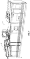
- FIG. 1 and 2 there is shown an exemplary laser based printing system 2 divided into a scanner section 6, controller section 7, and printer section 8.
- the fluorescent lamp assembly including the heater and control circuits to be discussed below, are associated with scanner section 6. While a specific printing system is shown and described, the present invention may be used with other types of printing systems such as light lens copying onto a photoreceptor, ink jet, ionographic, etc.
- scanner section 6 incorporates a transparent platen 20 on which a document 22 to be scanned is located.
- One or more linear arrays 24 are supported for reciprocating scanning movement below platen 20.
- An optical assembly 23 comprises a plurality of optical components which move together as a single unit. The components include a linear fluorescent lamp assembly 25, with associated reflector 26, and baffle 27 which cooperate to direct a narrow beam of high intensity light emitted from the lamp aperture onto an incremental area of the platen. Also included in assembly 23 are a reduction lens 27, and mirrors 28, 29, and 30, which cooperate to focus the reflected illumination lines from platen 20 and the document being scanned thereon onto array 24.
- Array 24, which may comprise a two row CCD photo sensor is illuminated by the focused band of illumination and generates image signals or pixels representative of the image scanned which after suitable processing by processor 35, are outputted to controller section 7.
- Processor 35 converts the analog image signal outputs of array 24 to digital signals and processes the digital image signals as required to enable system 2 to store and handle the image data in the form required to carry out the job programmed. Processor 35 also provides enhancements and changes to the image signals such as filtering, thresholding, screening, cropping, reduction/enlarging, etc.
- controller section 7 is, for explanation purposes, divided into an image input controller 40, an interface (UI) 42, a system controller 44, a main memory 46, an image manipulation section 68, and an image output controller 50.
- the scanned image data input from processor 35 of scanner section 6 is operated on by controller section 7.
- the output of controller 7 operates a Raster Output Scanner (ROS) 52 in printer 8 .
- ROS 52 has a laser which generates output beams 54 which are in turn scanned across a moving photoreceptor located in print module 56. Image lines are exposed at the photoreceptor with each scan to create a latent electrostatographic image of the document input.
- the lamp assembly 25 in a preferred embodiment, is a T8, (2.54 cm (1") Diameter) EHO lamp, which operates with a current of 2 amps and reaches an operating envelope temperature of approximately 149°C (300°F). At these relatively high temperatures, the lamp is subject to thermal instabilities along its length resulting, if uncompensated, in unwanted variations in the exposure level at the sensor array 24. Compensation for the instability is provided by attaching a heater blanket to the lamp and attaching a bifurcated electrical input connection to the heater to permit each half of the heater to be independently powered on and off. Referring now to Figure 4, there is shown illumination lamp assembly 25.
- the assembly comprises an elongated fluorescent lamp 58 having an envelope 60 with a phosphor layer formed on the inner surface and a quantity of mercury and an inner rare gas sealed within the envelope 60. Electrodes 62, 64, which include filaments 66, 68 are sealed in end caps 70, 72. Aperture 74 is provided to permit a band of illumination to be emitted and directed to platen 20 ( Figure 3).
- a heater blanket 80 is wrapped around the entire lamp envelope save for the aperture area and a small rectangular cold spot area to which the shoe of a Peltier cooler 81 is attached.
- Blanket 80 in a preferred embodiment is a high temperature polyamide impregnated fiberglass structure.
- a high density resistive grid work pattern is formed within the jacket, in series connection, from one end of the jacket to the other.
- Central thermostats 82 and 84 are located on the jacket at symmetrical locations distant from the lamp envelope midpoint.
- Two additional filament control thermostats 86, 88 are located at the ends of the lamp for purposes of separately controlling the heating temperature at the filament end zones as will be seen.
- heater power is supplied directly from a 208 volt AC power line which is fuse protected and passed to jacket 80 through heater power supply 90.
- Operating power to the lamp is provided by illumination ac power supply 92 in response to a lamp turn-on (scan mode) signal.
- lamp turn-on (scan mode) signal In both standby and run low voltage AC filament power is applied to filament 66, 68 from a transformer in the lamp supply.
- Peltier control circuit 94 incorporates the temperature control (both cooling and heating) and heat exchange components in circuits which are used to maintain the mercury cold spot temperature at the desired value.
- a cold spot setpoint of 42°C (108°F) was found to be optimum for this embodiment.
- lamp 58 operates continuously with a power input of approximately 152 watts, and draws a two amp current.
- Lamp outer wall temperature at locations away from the filaments 66, 68 and cold spot during either standby or run are typically in the 149°C (300°F) temperature range.
- Heater power to the blanket 80 is controlled by the miniature high precision thermostats 82, 84, 86 and 88 mounted to the rear surface of the blanket 80. For the particular mounting geometry used in this enablement, it was empirically determined that 270°F miniature precision thermostats would maintain the blanket 80 at a temperature above that of the lamp in both standby and run modes.
- temporal variations in the illumination output of the lamp are reduced by maintaining the temperature of the blanket 80 at a uniform temperature of approximately 149°C (300°F) along its entire length in standby and in operation.
- This is enabled by firstly wrapping the jacket around the entire lamp envelope 60 surface, including the filament areas, but providing independent control of the left and right hand sides of the jacket. Further, each side has a further modification which permits separate control of the heater blanket portion which is adjacent to the filament end areas.
- resistor 100 the resistance of jacket 80 from a midpoint location point A to a right hand location point B
- the jacket resistance from point B to the right hand end of the jacket is represented by resistor 102.
- resistor 104 the resistance of jacket 80 from point A to point C is designated as resistor 104, and from point C to the left end of the jacket by resistor 106.
- Typical values for each set of resistors are 476 and 100 ohms, respectively.
- Heater power supply 90 is connected across point A and the ends of the lamp. Effectively, as shown in Figure 5, a bifurcated heater control is enabled. In standby operation thermostats 82, 84 are normally closed, and thermostats 86, 88 are normally open. Resistors 102, 104 and 106 are connected in series and power from heater supply 90 causes current to flow through the resistors producing a uniform temperature of 149°C (300°F) along the heater blanket length.
- the blanket is maintained at this relatively high temperature of 149°C (300°F) (77°C (170°F) is conventional in the art) to prevent mercury/phosphor attachment to interior areas of the envelope other than the cold spot, a phenomenon which occurs when a lamp operating at high envelope temperatures is returned to a relatively low standby temperature.
- the filament zone (areas surrounding filaments 66, 68) immediately become much hotter than the central portion of the lamp envelope reaching possible transient temperatures of 246°C (475°F).
- the heater blanket 80 would be damaged by the excess heat supplied by the main portion of the heater blanket during the on portion of the blanket cycle.
- the thermostats 86, 88 sense the temperature rise at the back of the blanket to be above 132°C (270°F) and close, shunting the current in heater sections 102, 106 back into resistors 100 and 104 respectively.
- the thermostats 82, 84 will open only if the temperature on the back surface of the heater blanket exceeds 132°C (270°F), and are designed to cycle on and off during both standby and run modes of operation. The net result is that temporal variations in the lamp wall temperature profile along the length of the lamp are minimized while in standby; while fully on or while transitioning from standby to the full condition.
- the benefits of the dominance of the heater blanket control temperature is the substantial reduction in mercury pressure swings during full on operation and when transitioning from standby to the full on mode.
- the higher blanket temperature control point needed to prevent the lamp from exceeding the heater blanket control range in run mode also serves to reduce or slow the process of mercury/phosphor attachment at the internal walls of the lamp envelope during standby, leading to a reduction of temperature induced pressure variations during the transient period resulting in an enhancement of the axial illumination profile stability during the transition.
- the extension of the heater blanket to the extreme ends of the lamp further controls mercury pressure changes by insuring that mercury is not thermally trapped in the end regions of the lamp adjacent to the filaments during prolonged standby in a cold environment.
- the addition of heat in this zone also reduces the time taken for mercury condensed in these extreme ends of the lamp to be vaporized and migrate back to the cold spot. This rapid end stabilization allows the lamp to be stabilized and ready for use after a relatively short initial warmup period even if the room environment when powered off was relatively cold. This reduces the time a user must wait during the initial power up process.
- a barrier layer 91 is placed between the jacket and the lamp envelope ( Figure 4) to prevent localized heating which can cause delamination or thermal damage to the blanket at lamp energization.
- a TeflonTM lubricant is applied between layer 91 and the glass envelope of the lamp. The material prevents inadvertent sticking of the blanket to the lamp by a condensed polyamide from the blanket or contaminations. This provides for easy removal of the blanket from the lamp. While the lamp assembly heater controls of the present invention are especially useful in operating in high illumination applications, they are also suitable for other document scanning functions requiring a temporally stable illumination profile.
Landscapes
- Physics & Mathematics (AREA)
- General Physics & Mathematics (AREA)
- Engineering & Computer Science (AREA)
- Automation & Control Theory (AREA)
- Control Of Resistance Heating (AREA)
- Light Sources And Details Of Projection-Printing Devices (AREA)
- Facsimile Scanning Arrangements (AREA)
- Exposure Or Original Feeding In Electrophotography (AREA)
- Control Of Exposure In Printing And Copying (AREA)
Description
Claims (15)
- A fluorescent lamp assembly (25) comprising, in combination, an elongated fluorescent lamp (58) containing an excess of mercury at a cold spot therein, said lamp (58) adapted when energized by a power source (92) to emit light radiation through a clear apertured slit (74), a heater blanket (80) around a portion of the surface of the lamp (58), and,
power control means for controlling power to said heater blanket (58) characterised in that said lamp heater blanket (80) wrapped around the lamp envelope extends from one end of the lamp (58) to the other, and bifurcated heating control means for independently applying power to each half of said blanket (80) so as to maintain the lamp temperature profile at a constant value during both the lamp operational phase as well as standby. - A lamp assembly (25) according to claim 1, characterised in that said power input to said blanket (80) causes the blanket (80) to operate at a temperature above the operating temperature of the lamp (58).
- A lamp assembly (25) as claimed in claim 1 or 2, characterised by circuit means (86, 88) for preventing overheating and damage to the end areas of said heater blanket (80) adjacent to the filaments (66, 68) at the end of said lamp (58).
- A fluorescent lamp assembly (25) as claimed in claim 1, characterised in that said bifurcated power control circuit includes a first and second temperature sensing and switching means (82, 86; 84, 88) operatively coupled to each half of said heater blanket (80), respectively.
- A fluorescent lamp assembly (25) according to claim 3, characterised in that said first temperature sensing and switching means (82, 86) includes in series a first thermostat (86) connected to said blanket (80) at a location adjacent one end of said lamp (58), and in the vicinity of a first lamp filament (66), and a second thermostat (82) attached to said blanket (80) at a location intermediate the center of the lamp (58) and said first thermostat, and wherein said second temperature sensing and switching means (84, 88) includes in series a third thermostat (88) connected to said blanket (80) at a location adjacent the opposite end of the lamp (58) and in the vicinity of a second lamp filament (68), and a fourth thermostat (84) attached to said blanket (80) at a location intermediate the center of the lamp (58) and said third thermostat (84).
- A fluorescent lamp assembly (25) according to claim 5, characterised in that said first and third thermostats (86, 88) are normally open during standby operation of the lamp (58) and said second and fourth thermostats (82, 84) are normally closed during said standby operation, all of said thermostats (82, 84, 86, 88) being adapted to change state when a preselected temperature, which is above the normal lamp operating temperature, is exceeded.
- A fluorescent lamp assembly (25) according to claim 2, characterised in that during said standby operation and run, said heater blanket input power induces a current through said blanket (80) to uniformly heat said blanket (80) to said preselected temperature which is higher than the normal maximum operating temperature of the lamp (58) and the unenergized heater blanket assembly.
- A fluorescent lamp assembly (25) according to claim 5 or claim 6, characterised in that during lamp energization, said first and third thermostats (86, 88) sense the higher temperature of the lamp (58) in the vicinity of the lamp filaments (66, 68) and close to shunt out the current from these end sections when the localized temperature exceeds the design limits.
- A lamp assembly (25) according to any one of claims 1 to 8, characterised by an aluminum sheet barrier layer (91) disposed between the heater blanket (80) and the lamp (58).
- A lamp assembly (25) according to Claim 9, characterised by a Teflon™ lubricant coated between said barrier layer (91) and said glass envelope (60) of the lamp (58).
- A lamp assembly (25) according to any one of claims 1 to 10, characterised in that said cold spot is optimized at approximately 42°C (108°F) by means of a cooling and heating control assembly (81) located proximate said cold spot.
- A lamp assembly (25) according to Claim 2, characterised in that said preselected lamp envelope temperature is set at approximately 149°C (300°F).
- An electrophotographic reproduction device wherein a document (22) in an object plane is scanned in a copy mode by an optical assembly (23) including at least a linear apertured fluorescent lamp (58) and a scanning mirror (26),
characterised in that the lamp (58) has a heater blanket (80) wrapped around the lamp envelope and attached to its surface from one end of the lamp (58) to the other and wherein heater input power to the blanket (80) is applied by means of bifurcated heating control means independently to both sides of the blanket (80) so as to maintain the lamp temperature profile at a constant value during both the lamp (58) operational phase as well as standby. - An electrophotographic printing machine having a scanning system for illuminating longitudinal sections of incremental width of an original document (22), and means for exposing a photosensitive medium to the scanned light image, the scanning system including, an elongated apertured fluorescent lamp (58) characterised by a lamp heater blanket (80) wrapped around the lamp envelope and extending from one end of the lamp (58)to the other, and bifurcated heating control means for independently applying power to each half of said blanket (80), and thermostat control means (82, 84, 86, 88) associated with each half of said blanket (80) and adapted to maintain a constant preselected temperature along the blanket length during both lamp standby and lamp energization.
- A machine as claimed in claim 14, characterised in that said thermostat control means (82, 84, 86, 88) are further adapted to remove power from the ends of the lamp (58) adjacent the lamp filament zones during lamp energization conditions.
Applications Claiming Priority (2)
| Application Number | Priority Date | Filing Date | Title |
|---|---|---|---|
| US07/590,428 US5029311A (en) | 1990-09-28 | 1990-09-28 | Stabilized fluorescent lamp for a document scanning system |
| US590428 | 1990-09-28 |
Publications (3)
| Publication Number | Publication Date |
|---|---|
| EP0478342A2 EP0478342A2 (en) | 1992-04-01 |
| EP0478342A3 EP0478342A3 (en) | 1992-06-03 |
| EP0478342B1 true EP0478342B1 (en) | 1998-06-24 |
Family
ID=24362236
Family Applications (1)
| Application Number | Title | Priority Date | Filing Date |
|---|---|---|---|
| EP91308821A Expired - Lifetime EP0478342B1 (en) | 1990-09-28 | 1991-09-27 | A fluorescent lamp assembly |
Country Status (5)
| Country | Link |
|---|---|
| US (1) | US5029311A (en) |
| EP (1) | EP0478342B1 (en) |
| JP (1) | JPH04306056A (en) |
| CA (1) | CA2048825C (en) |
| DE (1) | DE69129648T2 (en) |
Families Citing this family (18)
| Publication number | Priority date | Publication date | Assignee | Title |
|---|---|---|---|---|
| JP2513316B2 (en) * | 1989-06-09 | 1996-07-03 | 富士ゼロックス株式会社 | Image reader |
| US5602860A (en) * | 1995-04-19 | 1997-02-11 | Optelecom, Inc. | Laser thermal control using thermoelectric cooler |
| US5495361A (en) * | 1995-05-08 | 1996-02-27 | Agfa Division, Bayer Corporation | Method and apparatus for synchronizing the polarization control signal of an AC-polarized arc-discharge lamp with the exposure timing signals of a CCD line sensor |
| US5737674A (en) * | 1995-11-20 | 1998-04-07 | Minnesota Mining And Manufacturing Company | Vapor control system for and a liquid electrographic system |
| US5754208A (en) * | 1995-11-27 | 1998-05-19 | Xerox Corporation | Liquid ink printer having dryer with integral reflector |
| US5898275A (en) * | 1997-04-15 | 1999-04-27 | Xerox Corporation | Fluorescent lamp system including light blocking members to create uniform illumination along a florescent lamp |
| US6340225B1 (en) | 1999-01-19 | 2002-01-22 | Xerox Corporation | Cross flow air system for ink jet printer |
| US6305796B1 (en) | 1999-01-26 | 2001-10-23 | Xerox Corporation | Thermal ink jet printer having dual function dryer |
| US20020100863A1 (en) * | 2001-01-30 | 2002-08-01 | Spears Kurt E. | Optical image scanner with color and intensity compensation during lamp warmup |
| US20020140996A1 (en) * | 2001-04-02 | 2002-10-03 | Spears Kurt E. | Optical image scanner using pre-scan and post-scan compensation for illumination nonuniformity |
| DE10129755A1 (en) * | 2001-06-20 | 2003-01-02 | Wilken Wilhelm | Control gear for fluorescent tubes with built-in cooling point |
| US6656006B2 (en) * | 2002-01-31 | 2003-12-02 | Hewlett-Packard Development Company, Lp. | Fluorescent lamp and method for production |
| US6928707B2 (en) * | 2002-11-19 | 2005-08-16 | Hewlett-Packard Development Company, L.P. | CCFL wrapped with a heater wire, and machines for manufacturing same |
| US7433097B2 (en) * | 2003-04-18 | 2008-10-07 | Hewlett-Packard Development Company, L.P. | Optical image scanner with moveable calibration target |
| WO2005104183A2 (en) * | 2004-04-21 | 2005-11-03 | Philips Intellectual Property & Standards Gmbh | Lighting unit |
| TWI261857B (en) * | 2005-09-22 | 2006-09-11 | Lite On Technology Corp | Fluorescent tube holding device |
| US7623819B2 (en) * | 2006-10-03 | 2009-11-24 | Xerox Corporation | Heater controller system for a fusing apparatus of a xerographic printing system |
| US10162244B1 (en) | 2017-06-27 | 2018-12-25 | Taiwan Semiconductor Manufacturing Company, Ltd. | Configurable heating device |
Family Cites Families (4)
| Publication number | Priority date | Publication date | Assignee | Title |
|---|---|---|---|---|
| JPS5942534A (en) * | 1982-09-03 | 1984-03-09 | Fuji Xerox Co Ltd | Lighting device of copying machine |
| GB2168579B (en) * | 1984-07-02 | 1987-08-26 | Xerox Corp | Thermostatically-controlled heater |
| US4751551A (en) * | 1987-08-03 | 1988-06-14 | Xerox Corporation | Cooling mechanism for scanning lamp assembly |
| US4827313A (en) * | 1988-07-11 | 1989-05-02 | Xerox Corporation | Mechanism and method for controlling the temperature and output of an amalgam fluorescent lamp |
-
1990
- 1990-09-28 US US07/590,428 patent/US5029311A/en not_active Expired - Lifetime
-
1991
- 1991-08-08 CA CA002048825A patent/CA2048825C/en not_active Expired - Fee Related
- 1991-09-26 JP JP3248040A patent/JPH04306056A/en active Pending
- 1991-09-27 EP EP91308821A patent/EP0478342B1/en not_active Expired - Lifetime
- 1991-09-27 DE DE69129648T patent/DE69129648T2/en not_active Expired - Fee Related
Also Published As
| Publication number | Publication date |
|---|---|
| CA2048825A1 (en) | 1992-03-29 |
| DE69129648D1 (en) | 1998-07-30 |
| CA2048825C (en) | 1997-04-29 |
| US5029311A (en) | 1991-07-02 |
| JPH04306056A (en) | 1992-10-28 |
| DE69129648T2 (en) | 1998-12-10 |
| EP0478342A2 (en) | 1992-04-01 |
| EP0478342A3 (en) | 1992-06-03 |
Similar Documents
| Publication | Publication Date | Title |
|---|---|---|
| US5029311A (en) | Stabilized fluorescent lamp for a document scanning system | |
| US5095336A (en) | Temperature control of a fluorescent lamp having a central and two end amalgam patches | |
| US5153745A (en) | Method and apparatus for compensating for illumination variations of a lamp in a document scanning system following extended lamp inactivity | |
| JPH06348824A (en) | Method and apparatus for detection of stability of illumination intensity | |
| EP0460719B1 (en) | Apparatus for stabilizing the quantity of light of a fluorescent lamp | |
| US4827313A (en) | Mechanism and method for controlling the temperature and output of an amalgam fluorescent lamp | |
| US5752129A (en) | Image forming apparatus having a supplemental heating source | |
| JP3242551B2 (en) | Lighting equipment | |
| JPH10210220A (en) | Document reading device | |
| JP3315495B2 (en) | Image forming device | |
| JP2586493B2 (en) | Document illumination device | |
| JPH02213888A (en) | Image forming device | |
| JP2586492B2 (en) | Document illumination device | |
| JP3267525B2 (en) | Image forming device | |
| JPH0534844A (en) | Light source temperature control device for image reading device | |
| JPH03134647A (en) | Picture reader | |
| JP3049119B2 (en) | Light source temperature controller for image reading device | |
| JP3564260B2 (en) | Image forming device | |
| JP3625419B2 (en) | Image reading device | |
| JPS60125836A (en) | Heating control method of fluorescent lamp of original exposing device | |
| JPH055552Y2 (en) | ||
| JPH0587957B2 (en) | ||
| KR0145870B1 (en) | Heater temperature controller for image forming apparatus | |
| JP2002174984A (en) | Image forming device | |
| JP2001083836A (en) | Image forming device |
Legal Events
| Date | Code | Title | Description |
|---|---|---|---|
| PUAI | Public reference made under article 153(3) epc to a published international application that has entered the european phase |
Free format text: ORIGINAL CODE: 0009012 |
|
| AK | Designated contracting states |
Kind code of ref document: A2 Designated state(s): DE FR GB |
|
| PUAL | Search report despatched |
Free format text: ORIGINAL CODE: 0009013 |
|
| AK | Designated contracting states |
Kind code of ref document: A3 Designated state(s): DE FR GB |
|
| 17P | Request for examination filed |
Effective date: 19921202 |
|
| 17Q | First examination report despatched |
Effective date: 19951214 |
|
| GRAG | Despatch of communication of intention to grant |
Free format text: ORIGINAL CODE: EPIDOS AGRA |
|
| GRAG | Despatch of communication of intention to grant |
Free format text: ORIGINAL CODE: EPIDOS AGRA |
|
| GRAH | Despatch of communication of intention to grant a patent |
Free format text: ORIGINAL CODE: EPIDOS IGRA |
|
| GRAH | Despatch of communication of intention to grant a patent |
Free format text: ORIGINAL CODE: EPIDOS IGRA |
|
| GRAA | (expected) grant |
Free format text: ORIGINAL CODE: 0009210 |
|
| AK | Designated contracting states |
Kind code of ref document: B1 Designated state(s): DE FR GB |
|
| REF | Corresponds to: |
Ref document number: 69129648 Country of ref document: DE Date of ref document: 19980730 |
|
| ET | Fr: translation filed | ||
| PLBE | No opposition filed within time limit |
Free format text: ORIGINAL CODE: 0009261 |
|
| STAA | Information on the status of an ep patent application or granted ep patent |
Free format text: STATUS: NO OPPOSITION FILED WITHIN TIME LIMIT |
|
| 26N | No opposition filed | ||
| REG | Reference to a national code |
Ref country code: GB Ref legal event code: IF02 |
|
| REG | Reference to a national code |
Ref country code: GB Ref legal event code: 746 Effective date: 20050512 |
|
| PGFP | Annual fee paid to national office [announced via postgrant information from national office to epo] |
Ref country code: FR Payment date: 20060908 Year of fee payment: 16 |
|
| PGFP | Annual fee paid to national office [announced via postgrant information from national office to epo] |
Ref country code: DE Payment date: 20060922 Year of fee payment: 16 |
|
| PGFP | Annual fee paid to national office [announced via postgrant information from national office to epo] |
Ref country code: GB Payment date: 20060927 Year of fee payment: 16 |
|
| GBPC | Gb: european patent ceased through non-payment of renewal fee |
Effective date: 20070927 |
|
| PG25 | Lapsed in a contracting state [announced via postgrant information from national office to epo] |
Ref country code: DE Free format text: LAPSE BECAUSE OF NON-PAYMENT OF DUE FEES Effective date: 20080401 |
|
| REG | Reference to a national code |
Ref country code: FR Ref legal event code: ST Effective date: 20080531 |
|
| PG25 | Lapsed in a contracting state [announced via postgrant information from national office to epo] |
Ref country code: FR Free format text: LAPSE BECAUSE OF NON-PAYMENT OF DUE FEES Effective date: 20071001 |
|
| PG25 | Lapsed in a contracting state [announced via postgrant information from national office to epo] |
Ref country code: GB Free format text: LAPSE BECAUSE OF NON-PAYMENT OF DUE FEES Effective date: 20070927 |