EP0478223B1 - Refillable tape dispensers - Google Patents
Refillable tape dispensers Download PDFInfo
- Publication number
- EP0478223B1 EP0478223B1 EP91308541A EP91308541A EP0478223B1 EP 0478223 B1 EP0478223 B1 EP 0478223B1 EP 91308541 A EP91308541 A EP 91308541A EP 91308541 A EP91308541 A EP 91308541A EP 0478223 B1 EP0478223 B1 EP 0478223B1
- Authority
- EP
- European Patent Office
- Prior art keywords
- retaining
- backcard
- portions
- flexible
- dispenser
- Prior art date
- Legal status (The legal status is an assumption and is not a legal conclusion. Google has not performed a legal analysis and makes no representation as to the accuracy of the status listed.)
- Expired - Lifetime
Links
- 239000004820 Pressure-sensitive adhesive Substances 0.000 claims description 3
- 238000005304 joining Methods 0.000 claims description 3
- 239000000463 material Substances 0.000 description 5
- 238000004519 manufacturing process Methods 0.000 description 4
- 238000000034 method Methods 0.000 description 4
- 238000000926 separation method Methods 0.000 description 4
- 239000004793 Polystyrene Substances 0.000 description 3
- 229920002223 polystyrene Polymers 0.000 description 3
- 238000007789 sealing Methods 0.000 description 3
- 239000000853 adhesive Substances 0.000 description 2
- 230000001070 adhesive effect Effects 0.000 description 2
- 238000010276 construction Methods 0.000 description 2
- 238000005336 cracking Methods 0.000 description 2
- 238000009825 accumulation Methods 0.000 description 1
- 238000007792 addition Methods 0.000 description 1
- 239000002390 adhesive tape Substances 0.000 description 1
- 230000002411 adverse Effects 0.000 description 1
- 230000004888 barrier function Effects 0.000 description 1
- 230000000295 complement effect Effects 0.000 description 1
- 230000008878 coupling Effects 0.000 description 1
- 238000010168 coupling process Methods 0.000 description 1
- 238000005859 coupling reaction Methods 0.000 description 1
- 230000002950 deficient Effects 0.000 description 1
- 230000007850 degeneration Effects 0.000 description 1
- 238000006073 displacement reaction Methods 0.000 description 1
- 238000009826 distribution Methods 0.000 description 1
- 230000007613 environmental effect Effects 0.000 description 1
- 230000006870 function Effects 0.000 description 1
- 230000002427 irreversible effect Effects 0.000 description 1
- 238000000465 moulding Methods 0.000 description 1
- 230000035939 shock Effects 0.000 description 1
- 238000003466 welding Methods 0.000 description 1
Images


Classifications
-
- B—PERFORMING OPERATIONS; TRANSPORTING
- B65—CONVEYING; PACKING; STORING; HANDLING THIN OR FILAMENTARY MATERIAL
- B65H—HANDLING THIN OR FILAMENTARY MATERIAL, e.g. SHEETS, WEBS, CABLES
- B65H35/00—Delivering articles from cutting or line-perforating machines; Article or web delivery apparatus incorporating cutting or line-perforating devices, e.g. adhesive tape dispensers
- B65H35/0006—Article or web delivery apparatus incorporating cutting or line-perforating devices
- B65H35/002—Hand-held or table apparatus
-
- B—PERFORMING OPERATIONS; TRANSPORTING
- B65—CONVEYING; PACKING; STORING; HANDLING THIN OR FILAMENTARY MATERIAL
- B65H—HANDLING THIN OR FILAMENTARY MATERIAL, e.g. SHEETS, WEBS, CABLES
- B65H35/00—Delivering articles from cutting or line-perforating machines; Article or web delivery apparatus incorporating cutting or line-perforating devices, e.g. adhesive tape dispensers
- B65H35/04—Delivering articles from cutting or line-perforating machines; Article or web delivery apparatus incorporating cutting or line-perforating devices, e.g. adhesive tape dispensers from or with transverse cutters or perforators
- B65H35/06—Delivering articles from cutting or line-perforating machines; Article or web delivery apparatus incorporating cutting or line-perforating devices, e.g. adhesive tape dispensers from or with transverse cutters or perforators from or with blade, e.g. shear-blade, cutters or perforators
-
- B—PERFORMING OPERATIONS; TRANSPORTING
- B65—CONVEYING; PACKING; STORING; HANDLING THIN OR FILAMENTARY MATERIAL
- B65H—HANDLING THIN OR FILAMENTARY MATERIAL, e.g. SHEETS, WEBS, CABLES
- B65H35/00—Delivering articles from cutting or line-perforating machines; Article or web delivery apparatus incorporating cutting or line-perforating devices, e.g. adhesive tape dispensers
- B65H35/0006—Article or web delivery apparatus incorporating cutting or line-perforating devices
- B65H35/002—Hand-held or table apparatus
- B65H35/0026—Hand-held or table apparatus for delivering pressure-sensitive adhesive tape
-
- Y—GENERAL TAGGING OF NEW TECHNOLOGICAL DEVELOPMENTS; GENERAL TAGGING OF CROSS-SECTIONAL TECHNOLOGIES SPANNING OVER SEVERAL SECTIONS OF THE IPC; TECHNICAL SUBJECTS COVERED BY FORMER USPC CROSS-REFERENCE ART COLLECTIONS [XRACs] AND DIGESTS
- Y10—TECHNICAL SUBJECTS COVERED BY FORMER USPC
- Y10T—TECHNICAL SUBJECTS COVERED BY FORMER US CLASSIFICATION
- Y10T403/00—Joints and connections
- Y10T403/53—Split end with laterally movable opposed portions
Definitions
- the present invention relates to a refillable tape dispenser for disbursing a supply of adhesive coated tape, which dispenser is adapted for use with an associated backcard for hanging the dispenser on a commercial display, and to a hub for such a dispenser.
- dispensers including a polymeric housing including a hub, a roll of tape including a core journaled on the hub and a length of pressure sensitive adhesive coated tape helically wound around the core, and a paper backcard attached at one end of the hub by which the dispenser can be hung on a display shelf or rack.
- the backcard is disposed around one end of the hub with the hub disposed within a through opening in the core and a portion of the backcard adjacent one side surface of the roll of tape.
- the backcard is held adjacent one side surface of the roll of tape and the roll of tape is prevented from sliding axially off the cylindrical outer surface of the hub by a series of tabs integral with the hub and formed by heat sealing or ultrasonically welding the tabs in a position projecting generally perpendicular to a longitudinal axis of the hub. While the backcard is reliably attached to the dispenser, the heat sealing or ultrasonic processes used to form the tabs are irreversible and thus result in a product which is non-reuseable and non-refillable. Also, the heat sealing process used to form the tabs requires time during the manufacturing process which increases the time needed to manufacture a dispenser.
- Non-reuseable dispensers are associated with environmental problems, such as problems related with disposal of spent dispensers.
- Many hand held tape dispensers are manufactured from polystyrene which has a relatively slow degeneration rate. These types of dispensers are used until the roll of tape is depleted and then disposed.
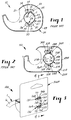
- FIGS 1 and 2 are illustrations of existing tape dispensers which can be re-used.
- the dispenser 10 depicted in Figure 1 is a SCOTCH brand transparent tape dispenser available from 3M Argentina.
- the dispenser 50 of Figures 2 and 2A is a NICHIBAN double sided tape dispenser available from Nichiban of Japan which has many parts that are essentially the same as the parts of the dispenser 10 and which have been identified by the same reference numeral to which has been added the suffix "A".
- Each dispenser 10, 50 includes a housing 20, 20A including a side wall 21, 21A, and a tubular hub 22, 22A having cylindrical inner 23, 23A and outer 24, 24A surfaces, and a first end 25A (Figure 2A) fixed to the side wall 21, 21A.
- the hub 22, 22A comprises a base portion 26A joined to the side wall 21, 21A opposite arcuate guide portions 27, 27A projecting axially from the base portion 26A, and first 28, 28A and second 29, 29A opposed arcuate arm portions having a distal end 30, 30A remote from the base portion 26A.
- the first 28, 28A and second 29, 29A arm portions project axially from the base portion 26A between the guide portions 27, 27A.
- the distal ends 30, 30A of the arm portions 28, 28A, 29, 29A include planar cam surfaces 31, 31A and lips 32, 32A; 33, 33A extending radially outward from the hub adjacent the planar cam surface 31, 31A and each of the arm portions 28, 28A, 29, 29A further have arcuate or sloping edges 34, 35, 36, 37; 34A, 35A, 36A, 37A adjacent their distal ends 30, 30A which are located at the edges of the planar cam surfaces 31, 31A.
- the dispenser 50 shown in Figure 2 includes an axially extending rib 51A that is believed to assist the hub 22A in holding the backcard 40A on the dispenser 50.
- Figures 7 and 7A show typical backcards 40, 40A used with the dispensers 10, 50 of Figures 1, 2 and 2A which include a hanging aperture 41, 41A adapted to afford display of the dispenser 10, 50, and through openings 42, 42A, 43, 43A disposed between an outer portion 49, 49A of the dispenser housing 20, 20A and the lips 32, 32A, 33, 33A of the hub 22, 22A.
- the backcard 40 of Figure 7 is used in conjunction with the dispenser 10 shown in Figure 1, and comprises cuts 44 and 45 which extend radially away from the through openings 42, 43.
- the cuts 44, 45 are adapted to permit flexing of the backcard 40 to afford passage of the cam surfaces 31 and lips 32, 33 of the hub 22 through the openings 42, 43 from one side of the backcard 40 to the other during joining of the backcard to the dispenser.
- the backcard 40A illustrated in Figure 7A is used in conjunction with the dispenser 50 shown in Figure 2. Unlike the guide portions 27 of the dispenser 10, the guide portions 27A of the dispenser 50 extend axially beyond the outer portion 49A of the dispenser housing and fit into large arcuate holes 52A in the backcard 40A ( Figure 2A). This feature is believed to assist in retaining the backcard upon the hub 22A.
- the dispensers 10, 50 described in Figures 1, 2 and 2A encounter problems when they are joined to the backcards 40, 40A.
- the cam surfaces 31, 31A and lips 32, 32A, 33, 33A of the hubs 22, 22A must penetrate the openings 42, 42A, 43, 43A of the backcards 40, 40A.
- the planar cam surfaces 31, 31A and the distal ends 30, 30A of the arm portions present blunt surfaces which are not readily adapted to penetrate the through openings 42, 42A, 43, 43A of the backcards 40, 40A.
- a failure to join the backcard to the dispenser may result in undesirable consequences such as an increase in the number of rejected dispensers on an assembly line. Such a result may also cause an accumulation or pile-up of dispensers on an assembly line of a high speed assembler which tends to cause assembler failure.
- the dispensers disclosed in Figures 1, 2 and 2A also encounter problems with retaining the backcards 40, 40A between the lips 32, 32A, 33, 33A and the outer portion 49, 49A of the dispenser housing 20, 20A.
- the hand held dispensers 10, 50 are subject to a variety of loads such as torque, vibration and shock loads, which can cause the backcards 40, 40A to separate from the hubs 22, 22A. This is an undesirable result for the user as the user must manually replace the backcards in order to hang the dispenser on a commercial display.
- One solution to this problem has been to place a length of adhesive coated tape across the backcard 40, 40A and the camming surface 31, 31A. This solution, however, is expensive and requires at least one additional step during the manufacturing process.
- backcards which utilize through openings with "square" edges or edges formed by the intersection of two straight members tend to tear at the intersection of the two straight members, particularly when the dispenser and backcard are dropped. Stress is believed to be concentrated at the intersection of the two straight members which tends to cause the backcard to tear at the intersection. Such tearing of the backcard tends to lead to backcard rotation and backcard separation from the dispenser. Excessive backcard rotation adversely affects the product's presentation to the consumer, and backcard separation requires extra effort by the user as the backcard must again be attached to the dispenser before the dispenser may be displayed on a commercial display rack.
- a dispenser of a type somewhat similar to the above commercial dispensers is disclosed in DE-C-958631 in which there is provided a hub for the core of a roll of adhesive tape with retaining lugs on the hub.
- the present invention seeks to provide a hub used in a refillable tape dispenser which dispenser is readily adapted to penetrate through openings of a backcard.
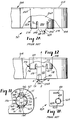
- FIG. 3 a first embodiment of dispenser 100 according to the present invention with a roll 1 of tape 6 comprising a core 2 ( Figure 4) having inner 3 and outer 4 cylindrical surfaces and a through opening 5 defined by the cylindrical inner surface, and a length of pressure sensitive adhesive coated tape 6 helically wound around the core 2.
- the refillable tape dispenser 100 comprises a housing 102 including a side wall 104, and a tubular hub 106 having a longitudinal axis A defining an axial direction, cylindrical inner 105 and outer 107 surfaces, and a first end 108 adjacent the side wall 104.
- a convex arcuate portion 199 At the junction between the inner surface 105 of the hub 106 and the side wall 104 is a convex arcuate portion 199.
- the hub 106 comprises a continuous base portion 112 joined to the side wall 104 by being integral therewith, first 116 and second 118 opposed arcuate guide portions projecting axially from the continuous base portion 112, and first 120 and second 122 opposed arcuate flexible portions having a distal end 123 remote from the continuous base portion 112.
- the first 120 and second 122 opposed arcuate flexible portions project axially from the continuous base portion 112 between the guide portions 116, 118 and have axially extending side surfaces 119, 121, 125, 129 defining non-diametrical chords C1 and C2 for the hub 106.
- non-diametrical chords refers to the geometry and locations of the surfaces 119, 121, 125, 129 ( Figure 11).
- a line cannot be drawn between points on at least two of the axially extending side surfaces 119, 121, 125, 129 which both passes through a center of the hub 106 and which remains parallel to at least two of the axially extending side surfaces 119, 121, 125, 129.
- the axially extending side surfaces 119, 121, 125, 129 are referred to as forming non-diametrical chords for the hub 106.
- a line drawn between opposite side surfaces of different arm portions (such as S1 and S4 in Figure 2) approximates a diametrical chord as opposite surfaces which are disposed along the same arm portion (S1 and S2 for example) converge toward the center C of the hub.
- Opposite surfaces which are located on the same arm portion (such as S3 and S4) are not parallel with each other and end in an arcuate or sloping edges 34, 35, 36, 37; 34A, 35A, 36A, 37A.
- the housing 102 of the dispenser 100 includes a retaining lug 131, 132 at the distal end 123 of each of the flexible portions 120, 122 and the retaining lugs 131, 132 have a remote end 135 spaced axially from the flexible portions 120, 122.
- first retaining surfaces 140, 142 adjacent the flexible portions 120, 122 which project radially outward of the flexible portions 120, 122 to outer edges 75, 77 and second retaining surfaces 141, 143 adjacent the flexible portions 120, 122, which project radially inward of the flexible portions 120, 122 to inner edges 74, 76.
- the retaining lugs each include first and second camming surfaces 161, 162, 165, 166 which diverge from the remote ends 135 of the retaining lugs 131, 132 toward the outer edges 75, 77 of first retaining surfaces 140, 142 and the inner edges 74, 76 of the second retaining surfaces 141, 143.
- Each of the lugs 131, 132 also include third and fourth camming surfaces 163, 167, 164, 168 which diverge from the remote end 135 of the retaining lugs 131, 132 toward the axially extending side surfaces 119, 121, 125, 129 defining the non-diametrical chords C1, C2 (figure 11) for the hub 106.
- the cam surfaces form a relatively sharp edge at the remote end 135 of the retaining lugs 131, 132 which affords efficient coupling of the dispenser 100 to a backcard.
- the relatively sharp edges at the remote ends 135 of the retaining lugs 131, 132 of the present invention are particularly well adapted to pierce a hole in a backcard and thereby afford efficient assembly using high speed assembly machinery.
- the first retaining surfaces 140, 142 of the retaining lugs 131, 132 assist in retaining the core 2 journaled on the outer surface 107 of the hub 106 by restricting axial movement of the core 2 relative to undeflected first and second flexible portions 120, 122, since in an undeflected position, the radius of the radially outermost portion 75, 77 of the first retaining surfaces 140, 142 is larger than the inner radius 3 of the core 2.
- the first retaining surfaces 140, 142 also combine with the second retaining surfaces 141, 143 to prevent backcard separation from the dispenser 100. While the prior art dispensers have the capacity to be refilled, the radially outward extending lips 32, 32A; 33, 33A and arcuate or sloping edges 34, 35, 36, 37; 34A, 35A, 36A, 37A encounter difficulties in maintaining the backcard coupled to the dispensers 10, 50. It is believed that one mode of failure for the prior art dispensers is that the backcards 40, 40A tend to lap over the distal ends of the lips 32, 32A, 33, 33A and thereafter separate from the hubs 22, 22A.
- the rounded or sloping edges 34, 35, 36, 37, 34A, 35A, 36A, 37A combined with the uniform width of backcard holes 42, 42A, 43, 43A tend to allow the backcard to lap over the distal end of the lips 32, 32A, 33, 33A.
- the axially extending side surfaces 119, 121, 125, 129 of the flexible portions 120, 122 of the present invention abruptly end in edges E ( Figure 12) to provide a barrier that prevents the backcard from lapping over the lugs 131, 132.
- the first and second retaining surfaces 140, 141, 142, 143 of the present invention extend both radially outward and radially inward of a hole (320A, Figure 8 for example) in a backcard to further deter the backcard from lapping over the retaining lugs 131, 132 and thereafter separating from the hub 106.
- the edges E ( Figure 12) of the present invention are an important feature for preventing backcard separation from the dispenser.
- the hub 106 for the dispenser 100 comprises axially extending side surfaces 119, 121, 125, 129 defining non-diametrical chords for the hub 106.
- the surfaces 119, 121, 125, 129 are parallel to each other and are generally perpendicular to the first and second retaining surfaces 140, 142. As shown in Figure 12, the surfaces 119, 121, 125, 129 come to an abrupt end at the edge E of the retaining lugs 131, 132.
- an end surface 301A of a hole in the backcard is proximate the surfaces 119, 121, 125, 129.
- the side surfaces 119, 121, 125, 129 and the retaining surfaces 140, 141, 142, 143 function to hold the backcard onto the dispenser and deter the end surface 301A from lapping over the lugs 131, 132 and thereafter separating from the dispenser.
- the dispenser 100 comprises a unitary construction of a flexible material.
- a material that is particularly adapted for construction of the dispenser 100 is Polystyrene which affords sufficient flexing of the flexible portions 120, 122 to permit axial passage of the inner cylindrical surface 3 of the core 2 of the depleted and replacement tape rolls.
- the material comprising the flexible portions 120, 122 should have the capacity to deflect without breaking or cracking.
- Polystyrene has a modulus of elasticity of between 100,000 and 300,000 psi (pounds per square inch) which provides flexible portions 120, 122 with an appropriate spring constant.
- any suitable material or combination of materials that affords sufficient flexing of the flexible portions 120, 122 without cracking or breaking may be used to construct the dispenser.
- the length of the groove G1 between the guide portions 116, 118 and the flexible portions 120, 122 may also be manipulated to control the flexibility of the flexible portions 120, 122.
- FIGS 5 and 6 illustrate a second embodiment of a dispenser according to the present invention generally designated by the reference number 101 which has many parts that are essentially the same as the parts of the dispenser 100 and which have been identified by the same reference numeral to which has been added the suffix "A".
- the dispenser 101 comprises a housing 102A including a side wall 104A, and a tubular hub 106A having a longitudinal axis A defining an axial direction, cylindrical inner 105A and outer 107A surfaces, and a first end 108A fixed to the side wall 104A.
- a convex arcuate portion 199A At the junction between the inner surface 105A of the hub 106A and the side wall 104A.
- the hub 106A comprises a continuous base portion 112A joined to the side wall 104A by being integral therewith, first 116A and second 118A opposed arcuate guide portions projecting axially from the continuous base portion 112A, and first 120A and second 122A opposed arcuate flexible portions having a distal end 123A remote from the continuous base portion 112A.
- the first 120A and second 122A flexible portions project axially from the continuous base portion 112A between the guide portions 116A and 118A and have axially extending side surfaces (similar to surfaces 119, 121, 125, 129 of the first embodiment of the present invention) defining non-diametrical chords (not shown) for the hub 106A.
- the dispenser 101 also comprises retaining lugs 131A, 132A at the distal ends 123A of each of the flexible portions 120A, 122A and the retaining lugs 131A, 132A have a remote end 135A spaced axially from the flexible portions 120A, 122A.
- first retaining surfaces 140A, 142A which project radially outward of the flexible portions 120A, 122A and have outer edges 75A, 77A, and second retaining surfaces 141A, 143A which project radially inward of the flexible portions 120A, 122A and have inner edges 74A, 76A.
- the retaining lugs 131, 132A each comprise first 151, 154 and second 152, 153 camming surfaces diverging from the remote end 135A of the retaining lugs 131A, 132A toward the outer edges 75A, 77A of the first retaining surfaces 140A, 142A and the inner edges 74A, 76A of the second retaining surfaces 141A, 143A.
- the cam surfaces 153, 154 of retaining lug 131A diverge toward the outer edge 77A of the first retaining surface 140A and the inner edge 76A of the second retaining surface 141A.
- the embodiment of the present invention shown in Figures 5 and 6 includes side edge surfaces 158 extending generally perpendicular to the first and second retaining surfaces 140A, 141A, 142A, 143A of the retaining lugs 131A, 132A and co-planar with a corresponding one of the axial extending side surfaces (not shown but similar to 119, 121, 125, 129 of Figure 12) defining non-diametrical chords for the hub 106A.
- the side edge surfaces 158 of the lugs 131A, 132A of the dispenser 101 of the second embodiment provide additional edge surfaces which further deter an edge portion 301A ( Figure 8) of a hole in a backcard from lapping over the lugs 131A, 132A and thereafter separating from the dispenser 101.
- the dispensers of the present invention may be constructed using high speed assembly machinery.
- the high speeds of such machinery create disorder along the assembly line by causing vibrations and other forces which tend to disperse the locations of the dispensers.
- the dispensers are located side to side as shown in Figure 14.
- the dispensers may be subject to compressive forces in the direction of the axis of the tubular hub 206. Such compressive forces tend to cause one or more dispensers to "pop-up" or rise above the other dispensers on the assembly line.
- a random distribution of dispensers along the assembly line is undesirable as it may lead to assembly line failure such as jamming.
- dispensers 200 according to a third embodiment of the present invention provide means for controlling the relative positions of the dispensers and for preventing a dispenser from "popping-up" relative to the remaining dispensers due to compressive forces. This feature assists in preventing assembly failure in high speed assembly machinery.
- Figures 13 and 14 illustrate a third embodiment of dispenser according to the present invention generally designated by the reference numeral 200.
- the dispenser 200 comprises a housing 202 including a side wall 204, and a tubular hub 206 having a longitudinal axis A defining an axial direction, cylindrical inner 205 and outer 207 surfaces, and a first end 208 fixed to the side wall 204.
- a convex arcuate portion 299 At the junction between the inner surface 205 of the hub 206 and the side wall 204 is a convex arcuate portion 299 for affording a "nesting" feature later to be explained in greater detail.
- the hub 206 comprises a continuous base portion 212 joined to the side wall 204 by being integral therewith, first 216 and second 218 opposed arcuate guide portions projecting axially from the continuous base portion 212, and first 220 and second 222 opposed arcuate flexible portions having a distal end 223 remote from the continuous base portion 212.
- the first 220 and second 222 flexible portions project axially from the continuous base portion 212 between the guide portions 216, 218 and have axially extending side surfaces 219, 221, 225, 229 defining non-diametrical chords C5 and C6 for the hub 206 ( Figure 13).
- retaining lug 231, 232 at the distal end 223 of each of the flexible portions 220, 222 and the retaining lugs 231, 232 have a remote end 235 spaced axially from the flexible portions 220, 222.
- the retaining lugs 231, 232 also each have a first retaining surface 240, 242 adjacent the distal end of the flexible portion 220, 222 which projects radially outward of the flexible portion 220, 222 and have outer edges 275, 277 and a second retaining surface 241, 243 also adjacent the distal end of the flexible portion 220, 222, which projects radially inward of the flexible portion 220, 222 and have inner edges 274, 276.
- the dispenser 200 includes retaining lugs each having four camming surfaces 261, 262, 263, 264; 265, 266, 267, 268 with first and second camming surfaces 261, 262; 265, 266 diverging from the remote end 235 of the retaining lugs 231, 232 toward the outer edges 275, 277 of the first retaining surfaces 240, 242 and the inner edges 274, 276 of the second retaining surfaces 241, 243 of the retaining lugs 231, 232 and with third and fourth camming surfaces 263, 267; 264, 268 diverging from the remote end 235 of the retaining lugs 231, 232 toward the axially extending side surfaces 219, 221, 225, 229 defining the non-diametrical chord C5, C6 ( Figure 13) for the hub 206.
- the retaining lugs 231, 232 have arcuate concave camming surfaces 262, 266 at their radially outermost portion which afford engagement with the arcuate, rounded convex surface 299 of the first end 208 of the tubular hub 206.
- the dispenser 101 shown in Figures 5 and 6 could have surfaces 151, 154 replaced with arcuate concave surfaces with a diameter between middle portions of the surfaces 151, 154 generally equal to the diameter between middle portions of the arcuate rounded convex surface 199A to form a dispenser according to the third embodiment of the present invention.
- the inner surface 105, 105A, 205 of the tubular hub 106, 106A, 206 opens through a planar outer surface portion of the sidewall 104, 104A, 204 to define a through opening T in the sidewall 104, 104A, 204.
- the convex arcuate portion 299 is adapted to nest against opposite portions of the first arcuate concave camming surfaces 262, 266 of a second refillable tape dispenser to maintain the relative positions of the tape dispensers, for example, as they traverse an assembly line L or during shipment of the dispensers.
- Figure 14 shows a pair of dispensers 200 according to the third embodiment of the present invention "meshed” or “nested” as they traverse an assembly line L.
- the frictional engagement between the first arcuate concave camming surfaces 262, 266 and the convex arcuate portion 299 deters displacement of the dispensers relative to one another.
- the diameter D of a middle portion of the convex arcuate surface 299 is approximately the same as the diameter D between middle portions of the first arcuate concave camming surfaces 262, 266.
- the arcuate geometry of the convex surfaces 299 and camming surfaces 262, 266 provides additional surface area for frictional, abutting engagement between the complementary concave and convex surfaces to retain the camming surfaces 262, 266 in engagement with the convex surface 299.
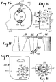
- Figures 8 - 10 show three embodiments of backcards which are coupled to the dispensers 100, 101, 200.
- the backcards 300A, 300B, 300C each have a hanging hole 330A, 330B, 330C for hanging a backcard 300A, 300B, 300C coupled to a dispenser 100, 101, 200 on a commercial display or rack.
- the backcards 300A, 300B, 300C may also be used to display miscellaneous indicia.
- Each of the backcards 300A, 300B, 300C are described in relation to the first embodiment of dispenser 100 but each of the backcards 300A, 300B, 300C may alternatively be used with each of the dispensers 100, 101, 200.
- Figure 8 illustrates a first embodiment of backcard generally designated by the reference numeral 300A.
- the backcard 300A has surfaces defining first and second chevron-shaped openings 320A, 324A, each of the openings including parallel end surfaces 301A, and two pairs of opposite parallel surfaces 311A disposed at obtuse angles with respect to each other and defining outer portions of the openings 320A, 324A.
- the pairs of opposite parallel surfaces 311A are joined to each other by concave arcuate surface portions defining a generally circular central portion 310A of the openings 320A, 324A.
- the backcard 300A is adapted to be disposed around the distal ends 123 of the first and second flexible portions 120, 122 as shown in Figures 3 and 5.
- the opposite parallel surfaces 311A are disposed adjacent the inner 105 and outer 107 surfaces of the flexible portions 120, 122 and extend from the central portion 310A to the parallel end surfaces 301A.
- the backcard 300A further comprises slits 305A which are disposed approximately along a line which bisects the included angle between an opposite parallel surface 311A and an end surface 301A.
- the slits 305A afford flexing of the backcard 300A to facilitate passage of the retaining lugs 131, 132 from one side of the backcard to the other through the chevron-shaped openings 320A, 324A during the assembly of the backcard/dispenser combination.
- the slits 305A provide means for quick and efficient assembly of the backcard/dispenser combination.
- the combination of any one of the dispensers 100, 101, 200 and backcard 300A comprises a combination with an efficient holding means for the backcard that is readily adapted to be manufactured quickly on high speed assembly machinery.
- Figure 9 illustrates a second embodiment of backcard generally designated by the reference numeral 300B which has many parts that are essentially the same as the parts of the backcard 300A and which have been identified by the same reference numeral to which the suffix "A" has been replaced by the suffix "B".
- the backcard 300B is identical to the backcard 300A except that in the backcard 300B, there is a slit 317 extending between the chevron-shaped openings 320B, 324B.
- the slit 317 affords extra flexing of the backcard 300B to further provide means for speedy assembly of the dispenser/backcard combination.
- Figure 10 illustrates a third embodiment of backcard generally designated by the reference numeral 300C which has many parts that are essentially the same as the parts of the backcard 300A and which have been identified by the same reference numeral to which the suffix "A" has been replaced by the suffix "B".
- the backcard 300C is identical to the backcard 300A except that in the backcard 300C, there are two additional slits 306 for each of the chevron-shaped openings 320C, 324C.
- the slits 306 are disposed approximately along a line which bisects the included angle between an opposite parallel surface 311C and an end surface 301C.
- the slits 306 afford flexing of the backcard 300C to facilitate passage of the retaining lugs 131, 132 from one side of the backcard 300C to the other through the chevron-shaped openings 320C, 324C during assembly of the backcard/dispenser combination.
- the backcard 300C comprises four slits for each of the chevron-shaped openings 320C, 324C but no slit extending between the chevron-shaped openings 320C, 324C.
- the additional slits 306 for each of the apertures 320C, 324C afford added flexing of the backcard 300C to provide speedy assembly of the dispenser/backcard combination, and to afford a lower failure rate when backcards are joined to a dispenser.
- the present invention may also be expressed as a combination of the novel hub features of the dispensers 100, 101, 200 with the backcards 300A, 300B, 300C.
- the chevron-shaped holes 320A, 324A of the backcards each include a relatively large circular central portion 310A proximate a middle portion of the chevron-shaped openings 320A, 324A for passage of the relatively sharp middle portion of the lugs 131, 132 during assembly, and have a narrower width along parallel surfaces 311A.
- the narrow portions of the chevron-shaped openings 320A, 324A near the ends 301A provide additional surface area to contact the first and second retaining surfaces 140, 141, 142, 143 and provide a narrower width in the holes adjacent the end E of lugs 131, 132 to thereby prevent the backcard from lapping over the lugs 131, 132.
- the relative large circular central portions 310A afford efficient assembly of the backcard/dispenser combination as the holes 310A align the center of the chevron-shaped openings 320A, 324A with the center of the retaining lugs 131, 132 and allow the retaining lugs 131, 132 to efficiently pierce the chevron-shaped openings 320A, 324A without jamming the machinery used to join the backcard/dispenser combination.
- the dispensers 100, 101, 200 may be manufactured using molding processes.
- the windows W1, W2, W3 shown in Figures 4, 6, 13 and 14 are required in some molds in order to form the lugs 131, 132 but are not necessary for the present invention.
- the windows W1, W2, W3 are sometimes required since it is difficult to mold the size and shape of the lugs 131, 132.
- the dispensers 100, 101, 200 may be manufactured using molds which do not require the windows W1, W2, W3 to form the lugs 131, 132 and thus, the windows W1, W2, W3 may be omitted from the present invention.
- Figure 14 illustrates a pair of dispensers 200 according to a third embodiment of the present invention which include a window W3.
- the retaining lugs 231, 232 are located adjacent the windows W3. If the lugs 231, 232 of a dispenser 200 become entangled within the windows W3 of an adjacent dispenser 200, a failure such as a defective dispenser or a jammed assembly line tends to occur.
- the windows W1, W2, W3 are omitted.
- the arcuate camming surfaces 262, 266 are especially desirable as they tend to prevent the lugs 231, 232 from becoming entangled with the windows W3 of an adjacent dispenser 200.
- Figures 15 through 18 illustrate a fourth embodiment of dispenser according to the present invention generally designated by the reference numeral 400.
- Figure 19 illustrates a backcard which is particularly suitable for use with the dispenser 400, generally designated by the reference number 370.
- the backcard 370 is generally identical to the backcard 300A shown in Figure 8 except that the backcard 370 includes a polygonal notch 371 that is adapted to position the backcard 370 to restrict interference between the backcard 370 and the teeth of the dispenser 400.
- Figure 16 illustrates the backcard 370 disposed around the distal ends of first 420 and second 422 opposed arcuate flexible portions of the dispenser 400.
- the backcard 370 has opposite major surfaces 372, 373 and edge surfaces between the major surfaces 372, 373 defining first and second chevron-shaped openings 374 between the major surfaces 372, 373.
- the edge surfaces define each of the openings and include generally parallel end surface portions 375, two pairs of opposite parallel surface portions 376 disposed at obtuse angles with respect to each other and defining outer portions of the openings 374, and concave arcuate surface portions 377 joining the pairs of opposite parallel surface portions 376 to each other and defining generally circular central portions of the openings 374.
- the backcard 370 may comprise slits 378 which are disposed approximately along a line which bisects the included angle between an opposite parallel surface portions 376 and the end surface portions 375 of the chevron-shaped openings 374 to afford flexing of the backcard 370 to facilitate passage of the retaining lugs 431 and 432 from one side of the backcard 370 to the other through the chevron-shaped openings 374.
- the dispenser 400 comprises a housing 402 including a side wall 404, and a hub 406.
- the hub 406 has a longitudinal axis defining an axial direction, inner 405 and outer 407 surfaces, and a first end 408 fixed to the side wall 404.
- the hub 406 also comprises first 420 and second 422 opposed flexible portions having distal ends 423 remote from the side wall 404. The first 420 and second 422 opposed flexible portions project axially from the side wall 404.
- a retaining lug 431 and 432 is located at the distal end 423 of each of the flexible portions 420 and 422.
- the dispenser 400 comprises ribs 450 located at the distal end 423 of each of the flexible portions 420 and 422.
- the ribs 450 project radially outward of the flexible portions 420 and 422 and have axially extending arcuate bearing surfaces 452.
- the arcuate surface portions 377 of the backcard 370 are positioned generally adjacent the bearing surfaces 452 of the ribs 450 so that the surface area of the flexible portions 420, 422 which impacts the surfaces defining the chevron-shaped openings 374 is increased to thereby restrict rotation of and damage to the backcard 370 particularly at the intersection between an end surface portion 375 and an opposite parallel surface portion 376.
- the ribs 450 may be fixed to the retaining lugs 431 and 432. Also optionally, the ribs 450 may include ramp surfaces 455 opposite the retaining lug disposed at an angle adapted to cam the flexible portions 420 and 422 radially inwardly when the core of a roll of tape (see Figure 4 or 6) is removed from the hub 406. This feature provides for convenient and efficient removal of a core of a roll of tape from the hub 406.
- the guide portions 116, 118 may be shortened as shown in Figures 4 and 14 or lengthened, as shown in Figure 6.
- the guide portions 216, 218 may be completely omitted from the hub 206 leaving only the continuous base portion 212 and the flexible portions 220, 222 in order to decrease the overall weight of the dispenser 200.
- the related grooves G1, G2, G3 may also be shortened or lengthened to control the flexibility and the spring constant of the flexible portions.
- the backcards used with the present invention may be a variety of shapes including but not limited to rectangular or square shapes with rounded corners.
- the scope of the present invention should not be limited to the structures described in this application, but only by structures described by the language of the claims and the equivalents of those structures.
Landscapes
- Containers And Packaging Bodies Having A Special Means To Remove Contents (AREA)
- Adhesive Tape Dispensing Devices (AREA)
- Details Of Rigid Or Semi-Rigid Containers (AREA)
- Cartons (AREA)
- Coating Apparatus (AREA)
- Unwinding Webs (AREA)
Description
- The present invention relates to a refillable tape dispenser for disbursing a supply of adhesive coated tape, which dispenser is adapted for use with an associated backcard for hanging the dispenser on a commercial display, and to a hub for such a dispenser.
- The art is replete with dispensers including a polymeric housing including a hub, a roll of tape including a core journaled on the hub and a length of pressure sensitive adhesive coated tape helically wound around the core, and a paper backcard attached at one end of the hub by which the dispenser can be hung on a display shelf or rack. The backcard is disposed around one end of the hub with the hub disposed within a through opening in the core and a portion of the backcard adjacent one side surface of the roll of tape.
- In a known non-reuseable type dispenser, the backcard is held adjacent one side surface of the roll of tape and the roll of tape is prevented from sliding axially off the cylindrical outer surface of the hub by a series of tabs integral with the hub and formed by heat sealing or ultrasonically welding the tabs in a position projecting generally perpendicular to a longitudinal axis of the hub. While the backcard is reliably attached to the dispenser, the heat sealing or ultrasonic processes used to form the tabs are irreversible and thus result in a product which is non-reuseable and non-refillable. Also, the heat sealing process used to form the tabs requires time during the manufacturing process which increases the time needed to manufacture a dispenser.
- Non-reuseable dispensers are associated with environmental problems, such as problems related with disposal of spent dispensers. Many hand held tape dispensers are manufactured from polystyrene which has a relatively slow degeneration rate. These types of dispensers are used until the roll of tape is depleted and then disposed.
- Figures 1 and 2 are illustrations of existing tape dispensers which can be re-used. The
dispenser 10 depicted in Figure 1 is a SCOTCH brand transparent tape dispenser available from 3M Argentina. Thedispenser 50 of Figures 2 and 2A is a NICHIBAN double sided tape dispenser available from Nichiban of Japan which has many parts that are essentially the same as the parts of thedispenser 10 and which have been identified by the same reference numeral to which has been added the suffix "A". Eachdispenser housing 20, 20A including aside wall tubular hub side wall hub side wall arcuate guide portions distal end guide portions - The
distal ends arm portions planar cam surfaces lips planar cam surface arm portions edges distal ends planar cam surfaces dispenser 50 shown in Figure 2 includes an axially extending rib 51A that is believed to assist thehub 22A in holding thebackcard 40A on thedispenser 50. - Figures 7 and 7A show
typical backcards dispensers hanging aperture 41, 41A adapted to afford display of thedispenser openings outer portion dispenser housing 20, 20A and thelips hub backcard 40 of Figure 7 is used in conjunction with thedispenser 10 shown in Figure 1, and comprisescuts openings cuts backcard 40 to afford passage of thecam surfaces 31 andlips hub 22 through theopenings backcard 40 to the other during joining of the backcard to the dispenser. - The
backcard 40A illustrated in Figure 7A is used in conjunction with thedispenser 50 shown in Figure 2. Unlike theguide portions 27 of thedispenser 10, theguide portions 27A of thedispenser 50 extend axially beyond theouter portion 49A of the dispenser housing and fit into largearcuate holes 52A in thebackcard 40A (Figure 2A). This feature is believed to assist in retaining the backcard upon thehub 22A. - During the manufacturing and assembly processes, the
dispensers backcards backcards dispensers cam surfaces lips hubs openings backcards planar cam surfaces distal ends openings backcards - The dispensers disclosed in Figures 1, 2 and 2A also encounter problems with retaining the
backcards lips outer portion dispenser housing 20, 20A. The hand helddispensers backcards hubs backcard camming surface - Also, backcards which utilize through openings with "square" edges or edges formed by the intersection of two straight members tend to tear at the intersection of the two straight members, particularly when the dispenser and backcard are dropped. Stress is believed to be concentrated at the intersection of the two straight members which tends to cause the backcard to tear at the intersection. Such tearing of the backcard tends to lead to backcard rotation and backcard separation from the dispenser. Excessive backcard rotation adversely affects the product's presentation to the consumer, and backcard separation requires extra effort by the user as the backcard must again be attached to the dispenser before the dispenser may be displayed on a commercial display rack.
- A dispenser of a type somewhat similar to the above commercial dispensers is disclosed in DE-C-958631 in which there is provided a hub for the core of a roll of adhesive tape with retaining lugs on the hub.
- The present invention seeks to provide a hub used in a refillable tape dispenser which dispenser is readily adapted to penetrate through openings of a backcard.
- According to a first aspect of this invention there is disclosed a hub in accordance with
claim 1 herein. - According to a second aspect of this invention there is disclosed a hub in accordance with
claim 5 herein. - According to a third aspect of this invention there is disclosed a refillable tape dispenser as disclosed in
claim 6 herein. - According to a fourth aspect of this invention there is disclosed a refillable tape dispenser as disclosed in claim 9 herein.
- The present invention will be further described with reference to the accompanying drawing wherein like reference numerals refer to like parts in the several views, and wherein:
- Figure 1 is a side view of a first prior art dispenser;
- Figure 2 is a side view of a second prior art dispenser;
- Figure 2A is an enlarged fragmentary top view of the dispenser shown in Figure 2 with portions broken away to show detail;
- Figure 3 is a perspective view of a first embodiment of dispenser according to the present invention together with a backcard coupled thereto;
- Figure 4 is a sectional view taken approximately along line 4-4 of Figure 3;
- Figure 5 is a perspective view of a second embodiment of dispenser according to the present invention illustrating the dispenser coupled to a backcard;
- Figure 6 is a sectional view taken approximately along line 6-6 of Figure 5;
- Figure 7 is a side view of a prior art backcard for use with the prior art dispenser of Figure 1;
- Figure 7A is a reduced side view of a prior art backcard for use with the prior art dispenser of Figure 2;
- Figure 8 is a side view of a first embodiment of backcard for a dispenser according to the present invention;
- Figure 9 is a side view of a second embodiment of backcard for a dispenser according to the present invention;
- Figure 10 is a side view of a third embodiment of backcard for a dispenser according to the present invention;
- Figure 11 is a side view of the first embodiment of dispenser according to the present invention having portions broken away to show detail;
- Figure 12 is an enlarged top view of the dispenser of Figure 11 having portions broken away to illustrate detail;
- Figure 13 is a side view of a third embodiment of dispenser according to the present invention having portions broken away to show detail;
- Figure 14 is a partially broken away enlarged side view of a pair of dispensers according to the third embodiment of the present invention illustrating the relative positions of the dispensers along an assembly line;
- Figure 15 is a side view of a fourth embodiment of dispenser according to the present invention having portions broken away to show detail;
- Figure 16 is an enlarged sectional view of the dispenser of Figure 15 coupled to a backcard and having portions broken away to feature details;
- Figure 17 is an enlarged top view of the dispenser of Figure 15 having portions broken away to illustrate detail;
- Figure 18 is a sectional view taken approximately along line 18-18 of Figure 16; and
- Figure 19 is a side view of a fourth embodiment of backcard for a dispenser according to the present invention which is particularly suited for the dispenser shown in Figure 15.
- Referring now to Figures 3, 4, 11 and 12 of the drawing there is shown a first embodiment of
dispenser 100 according to the present invention with aroll 1 oftape 6 comprising a core 2 (Figure 4) having inner 3 and outer 4 cylindrical surfaces and a throughopening 5 defined by the cylindrical inner surface, and a length of pressure sensitive adhesivecoated tape 6 helically wound around thecore 2. - The
refillable tape dispenser 100 comprises a housing 102 including aside wall 104, and atubular hub 106 having a longitudinal axis A defining an axial direction, cylindrical inner 105 and outer 107 surfaces, and afirst end 108 adjacent theside wall 104. At the junction between theinner surface 105 of thehub 106 and theside wall 104 is a convex arcuate portion 199. - The
hub 106 comprises acontinuous base portion 112 joined to theside wall 104 by being integral therewith, first 116 and second 118 opposed arcuate guide portions projecting axially from thecontinuous base portion 112, and first 120 and second 122 opposed arcuate flexible portions having adistal end 123 remote from thecontinuous base portion 112. The first 120 and second 122 opposed arcuate flexible portions project axially from thecontinuous base portion 112 between theguide portions side surfaces hub 106. - In this application, the phrase "non-diametrical chords" refers to the geometry and locations of the
surfaces side surfaces hub 106 and which remains parallel to at least two of the axially extendingside surfaces side surfaces hub 106. - In contrast, in some prior art dispensers, a line drawn between opposite side surfaces of different arm portions (such as S1 and S4 in Figure 2) approximates a diametrical chord as opposite surfaces which are disposed along the same arm portion (S1 and S2 for example) converge toward the center C of the hub. Opposite surfaces which are located on the same arm portion (such as S3 and S4) are not parallel with each other and end in an arcuate or
sloping edges - The housing 102 of the
dispenser 100 includes a retaininglug distal end 123 of each of theflexible portions remote end 135 spaced axially from theflexible portions distal end 123 of theflexible portions 120, 122), there are present first retaining surfaces 140, 142 adjacent theflexible portions flexible portions outer edges flexible portions flexible portions inner edges - According to a first embodiment of the present invention shown in Figures 3, 4, 11 and 12, the retaining lugs each include first and second camming surfaces 161, 162, 165, 166 which diverge from the remote ends 135 of the retaining lugs 131, 132 toward the
outer edges inner edges lugs remote end 135 of the retaining lugs 131, 132 toward the axially extendingside surfaces hub 106. The cam surfaces form a relatively sharp edge at theremote end 135 of the retaining lugs 131, 132 which affords efficient coupling of thedispenser 100 to a backcard. - In comparison to the blunt end surfaces of the prior art dispensers, the relatively sharp edges at the remote ends 135 of the retaining lugs 131, 132 of the present invention are particularly well adapted to pierce a hole in a backcard and thereby afford efficient assembly using high speed assembly machinery.
- The first retaining surfaces 140, 142 of the retaining lugs 131, 132 assist in retaining the
core 2 journaled on theouter surface 107 of thehub 106 by restricting axial movement of thecore 2 relative to undeflected first and secondflexible portions outermost portion inner radius 3 of thecore 2. - The first retaining surfaces 140, 142 also combine with the second retaining surfaces 141, 143 to prevent backcard separation from the
dispenser 100. While the prior art dispensers have the capacity to be refilled, the radially outward extendinglips sloping edges dispensers backcards lips hubs edges lips - In contrast the axially extending
side surfaces flexible portions lugs hub 106. - The edges E (Figure 12) of the present invention are an important feature for preventing backcard separation from the dispenser. The
hub 106 for thedispenser 100 comprises axially extendingside surfaces hub 106. Thesurfaces surfaces backcard 300A (Figure 8) is attached to the dispenser, anend surface 301A of a hole in the backcard is proximate thesurfaces end surface 301A from lapping over thelugs - To replace a depleted
roll 1 oftape 6, a user manually deflects theflexible portions cylindrical surface 3 of the depleted core. Preferably, thedispenser 100 comprises a unitary construction of a flexible material. A material that is particularly adapted for construction of thedispenser 100 is Polystyrene which affords sufficient flexing of theflexible portions cylindrical surface 3 of thecore 2 of the depleted and replacement tape rolls. The material comprising theflexible portions flexible portions flexible portions guide portions flexible portions flexible portions - Figures 5 and 6 illustrate a second embodiment of a dispenser according to the present invention generally designated by the
reference number 101 which has many parts that are essentially the same as the parts of thedispenser 100 and which have been identified by the same reference numeral to which has been added the suffix "A". Like thedispenser 100, thedispenser 101 comprises ahousing 102A including aside wall 104A, and atubular hub 106A having a longitudinal axis A defining an axial direction, cylindrical inner 105A and outer 107A surfaces, and afirst end 108A fixed to theside wall 104A. At the junction between theinner surface 105A of thehub 106A and theside wall 104A is a convexarcuate portion 199A. - The
hub 106A comprises a continuous base portion 112A joined to theside wall 104A by being integral therewith, first 116A and second 118A opposed arcuate guide portions projecting axially from the continuous base portion 112A, and first 120A and second 122A opposed arcuate flexible portions having a distal end 123A remote from the continuous base portion 112A. The first 120A and second 122A flexible portions project axially from the continuous base portion 112A between theguide portions 116A and 118A and have axially extending side surfaces (similar tosurfaces hub 106A. - Like the
dispenser 100, thedispenser 101 also comprises retaininglugs flexible portions 120A, 122A and the retaining lugs 131A, 132A have aremote end 135A spaced axially from theflexible portions 120A, 122A. At a proximal end of each of the retaining lugs 131A, 132A (or the distal end 123A of the flexible portions), there is present first retaining surfaces 140A, 142A which project radially outward of theflexible portions 120A, 122A and haveouter edges flexible portions 120A, 122A and haveinner edges 74A, 76A. The retaining lugs 131, 132A each comprise first 151, 154 and second 152, 153 camming surfaces diverging from theremote end 135A of the retaining lugs 131A, 132A toward theouter edges inner edges 74A, 76A of the second retaining surfaces 141A, 143A. For example, the cam surfaces 153, 154 of retaininglug 131A diverge toward theouter edge 77A of thefirst retaining surface 140A and the inner edge 76A of the second retaining surface 141A. - In contrast to the
dispenser 100, the embodiment of the present invention shown in Figures 5 and 6 includes side edge surfaces 158 extending generally perpendicular to the first and second retaining surfaces 140A, 141A, 142A, 143A of the retaining lugs 131A, 132A and co-planar with a corresponding one of the axial extending side surfaces (not shown but similar to 119, 121, 125, 129 of Figure 12) defining non-diametrical chords for thehub 106A. The side edge surfaces 158 of thelugs dispenser 101 of the second embodiment provide additional edge surfaces which further deter anedge portion 301A (Figure 8) of a hole in a backcard from lapping over thelugs dispenser 101. - The dispensers of the present invention may be constructed using high speed assembly machinery. The high speeds of such machinery create disorder along the assembly line by causing vibrations and other forces which tend to disperse the locations of the dispensers. For example, during some assembly operations the dispensers are located side to side as shown in Figure 14. During such operations the dispensers may be subject to compressive forces in the direction of the axis of the
tubular hub 206. Such compressive forces tend to cause one or more dispensers to "pop-up" or rise above the other dispensers on the assembly line. A random distribution of dispensers along the assembly line is undesirable as it may lead to assembly line failure such as jamming. However,dispensers 200 according to a third embodiment of the present invention provide means for controlling the relative positions of the dispensers and for preventing a dispenser from "popping-up" relative to the remaining dispensers due to compressive forces. This feature assists in preventing assembly failure in high speed assembly machinery. - Figures 13 and 14 illustrate a third embodiment of dispenser according to the present invention generally designated by the
reference numeral 200. - Like the
dispensers dispenser 200 comprises ahousing 202 including aside wall 204, and atubular hub 206 having a longitudinal axis A defining an axial direction, cylindrical inner 205 and outer 207 surfaces, and afirst end 208 fixed to theside wall 204. At the junction between theinner surface 205 of thehub 206 and theside wall 204 is a convexarcuate portion 299 for affording a "nesting" feature later to be explained in greater detail. - The
hub 206 comprises acontinuous base portion 212 joined to theside wall 204 by being integral therewith, first 216 and second 218 opposed arcuate guide portions projecting axially from thecontinuous base portion 212, and first 220 and second 222 opposed arcuate flexible portions having a distal end 223 remote from thecontinuous base portion 212. The first 220 and second 222 flexible portions project axially from thecontinuous base portion 212 between theguide portions side surfaces - Similar to the
dispensers lug flexible portions remote end 235 spaced axially from theflexible portions first retaining surface flexible portion flexible portion outer edges 275, 277 and asecond retaining surface flexible portion flexible portion inner edges - Like the
dispenser 100, thedispenser 200 includes retaining lugs each having fourcamming surfaces remote end 235 of the retaining lugs 231, 232 toward theouter edges 275, 277 of the first retaining surfaces 240, 242 and theinner edges remote end 235 of the retaining lugs 231, 232 toward the axially extendingside surfaces hub 206. However, instead of the relatively planar camming surfaces 162, 166 of thedispenser 100, according to the third embodiment of the present Invention, the retaining lugs 231, 232 have arcuate concave camming surfaces 262, 266 at their radially outermost portion which afford engagement with the arcuate, roundedconvex surface 299 of thefirst end 208 of thetubular hub 206. Moreover, thedispenser 101 shown in Figures 5 and 6 could havesurfaces surfaces convex surface 199A to form a dispenser according to the third embodiment of the present invention. - In each of the first, second and third embodiments the
inner surface tubular hub sidewall sidewall first end hub sidewall arcuate portion dispensers 200 according to the third embodiment, the convexarcuate portion 299 is adapted to nest against opposite portions of the first arcuate concave camming surfaces 262, 266 of a second refillable tape dispenser to maintain the relative positions of the tape dispensers, for example, as they traverse an assembly line L or during shipment of the dispensers. - Figure 14 shows a pair of
dispensers 200 according to the third embodiment of the present invention "meshed" or "nested" as they traverse an assembly line L. The frictional engagement between the first arcuate concave camming surfaces 262, 266 and the convexarcuate portion 299 deters displacement of the dispensers relative to one another. As shown in Figure 14, the diameter D of a middle portion of the convexarcuate surface 299 is approximately the same as the diameter D between middle portions of the first arcuate concave camming surfaces 262, 266. The arcuate geometry of theconvex surfaces 299 andcamming surfaces convex surface 299. - Figures 8 - 10 show three embodiments of backcards which are coupled to the
dispensers backcards hole backcard dispenser backcards dispenser 100 but each of the backcards 300A, 300B, 300C may alternatively be used with each of thedispensers - Figure 8 illustrates a first embodiment of backcard generally designated by the
reference numeral 300A. - The
backcard 300A has surfaces defining first and second chevron-shapedopenings parallel surfaces 311A disposed at obtuse angles with respect to each other and defining outer portions of theopenings parallel surfaces 311A are joined to each other by concave arcuate surface portions defining a generally circularcentral portion 310A of theopenings - The
backcard 300A is adapted to be disposed around the distal ends 123 of the first and secondflexible portions backcard 300A is joined to adispenser 100, the oppositeparallel surfaces 311A are disposed adjacent the inner 105 and outer 107 surfaces of theflexible portions central portion 310A to the parallel end surfaces 301A. - The
backcard 300A further comprisesslits 305A which are disposed approximately along a line which bisects the included angle between an oppositeparallel surface 311A and anend surface 301A. Theslits 305A afford flexing of thebackcard 300A to facilitate passage of the retaining lugs 131, 132 from one side of the backcard to the other through the chevron-shapedopenings slits 305A provide means for quick and efficient assembly of the backcard/dispenser combination. The combination of any one of thedispensers backcard 300A comprises a combination with an efficient holding means for the backcard that is readily adapted to be manufactured quickly on high speed assembly machinery. - Figure 9 illustrates a second embodiment of backcard generally designated by the
reference numeral 300B which has many parts that are essentially the same as the parts of thebackcard 300A and which have been identified by the same reference numeral to which the suffix "A" has been replaced by the suffix "B". Thebackcard 300B is identical to thebackcard 300A except that in thebackcard 300B, there is aslit 317 extending between the chevron-shapedopenings 320B, 324B. Theslit 317 affords extra flexing of thebackcard 300B to further provide means for speedy assembly of the dispenser/backcard combination. - Figure 10 illustrates a third embodiment of backcard generally designated by the reference numeral 300C which has many parts that are essentially the same as the parts of the
backcard 300A and which have been identified by the same reference numeral to which the suffix "A" has been replaced by the suffix "B". The backcard 300C is identical to thebackcard 300A except that in the backcard 300C, there are twoadditional slits 306 for each of the chevron-shapedopenings 320C, 324C. - Like the
slits 305A, theslits 306 are disposed approximately along a line which bisects the included angle between an oppositeparallel surface 311C and an end surface 301C. Theslits 306 afford flexing of the backcard 300C to facilitate passage of the retaining lugs 131, 132 from one side of the backcard 300C to the other through the chevron-shapedopenings 320C, 324C during assembly of the backcard/dispenser combination. - Unlike the
backcards openings 320C, 324C but no slit extending between the chevron-shapedopenings 320C, 324C. Theadditional slits 306 for each of theapertures 320C, 324C afford added flexing of the backcard 300C to provide speedy assembly of the dispenser/backcard combination, and to afford a lower failure rate when backcards are joined to a dispenser. - The present invention may also be expressed as a combination of the novel hub features of the
dispensers backcards - Using the first embodiment of backcard as illustrative, the chevron-shaped
holes central portion 310A proximate a middle portion of the chevron-shapedopenings lugs parallel surfaces 311A. The narrow portions of the chevron-shapedopenings ends 301A provide additional surface area to contact the first and second retaining surfaces 140, 141, 142, 143 and provide a narrower width in the holes adjacent the end E oflugs lugs central portions 310A afford efficient assembly of the backcard/dispenser combination as theholes 310A align the center of the chevron-shapedopenings openings - The
dispensers lugs lugs dispensers lugs - Figure 14 illustrates a pair of
dispensers 200 according to a third embodiment of the present invention which include a window W3. As shown in Figure 14, as thedispensers 200 travel axially along an assembly line L, the retaining lugs 231, 232, are located adjacent the windows W3. If thelugs dispenser 200 become entangled within the windows W3 of anadjacent dispenser 200, a failure such as a defective dispenser or a jammed assembly line tends to occur. Thus, in the preferred embodiment of the present invention, the windows W1, W2, W3 are omitted. Moreover, when the windows W3 are present, the arcuate camming surfaces 262, 266 are especially desirable as they tend to prevent thelugs adjacent dispenser 200. - Figures 15 through 18 illustrate a fourth embodiment of dispenser according to the present invention generally designated by the
reference numeral 400. Figure 19 illustrates a backcard which is particularly suitable for use with thedispenser 400, generally designated by thereference number 370. Thebackcard 370 is generally identical to thebackcard 300A shown in Figure 8 except that thebackcard 370 includes apolygonal notch 371 that is adapted to position thebackcard 370 to restrict interference between the backcard 370 and the teeth of thedispenser 400. - Figure 16 illustrates the
backcard 370 disposed around the distal ends of first 420 and second 422 opposed arcuate flexible portions of thedispenser 400. Thebackcard 370 has oppositemajor surfaces major surfaces openings 374 between themajor surfaces end surface portions 375, two pairs of oppositeparallel surface portions 376 disposed at obtuse angles with respect to each other and defining outer portions of theopenings 374, and concavearcuate surface portions 377 joining the pairs of oppositeparallel surface portions 376 to each other and defining generally circular central portions of theopenings 374. - Optionally the
backcard 370 may compriseslits 378 which are disposed approximately along a line which bisects the included angle between an oppositeparallel surface portions 376 and theend surface portions 375 of the chevron-shapedopenings 374 to afford flexing of thebackcard 370 to facilitate passage of the retaining lugs 431 and 432 from one side of thebackcard 370 to the other through the chevron-shapedopenings 374. - The
dispenser 400 comprises ahousing 402 including aside wall 404, and ahub 406. Like the previously mentioneddispensers hub 406 has a longitudinal axis defining an axial direction, inner 405 and outer 407 surfaces, and afirst end 408 fixed to theside wall 404. Thehub 406 also comprises first 420 and second 422 opposed flexible portions having distal ends 423 remote from theside wall 404. The first 420 and second 422 opposed flexible portions project axially from theside wall 404. A retaininglug distal end 423 of each of theflexible portions - Unlike the previously mentioned embodiments of the present invention, the
dispenser 400 according to the fourth embodiment comprisesribs 450 located at thedistal end 423 of each of theflexible portions ribs 450 project radially outward of theflexible portions arcuate surface portions 377 of thebackcard 370 are positioned generally adjacent the bearing surfaces 452 of theribs 450 so that the surface area of theflexible portions openings 374 is increased to thereby restrict rotation of and damage to thebackcard 370 particularly at the intersection between anend surface portion 375 and an oppositeparallel surface portion 376. It is believed that increasing the surface area reduces the unit pressure on the surfaces on theopenings 374. This feature provides a tape dispenser with an increased capacity to retain a backcard, which resists rotation of the backcard relative to the dispenser, and which resists damage from impulsive impacts such as when the backcard and dispenser are dropped. - Optionally, the
ribs 450 may be fixed to the retaining lugs 431 and 432. Also optionally, theribs 450 may include ramp surfaces 455 opposite the retaining lug disposed at an angle adapted to cam theflexible portions hub 406. This feature provides for convenient and efficient removal of a core of a roll of tape from thehub 406. - The present invention has now been described with reference to several embodiments thereof. It will be apparent to those skilled in the art that many changes or additions can be made in the embodiments described without departing from the scope of the present invention. For example, the
guide portions guide portions hub 206 leaving only thecontinuous base portion 212 and theflexible portions dispenser 200. The related grooves G1, G2, G3 may also be shortened or lengthened to control the flexibility and the spring constant of the flexible portions. Also, the backcards used with the present invention may be a variety of shapes including but not limited to rectangular or square shapes with rounded corners. Thus, the scope of the present invention should not be limited to the structures described in this application, but only by structures described by the language of the claims and the equivalents of those structures.
Claims (9)
- A hub (106; 106A; 206) with a longitudinal axis (A) defining an axial direction for use in a refillable tape dispenser (100; 101; 200; 400) including a housing (102; 102A; 202; 402) with a sidewall (104; 104A; 204; 404), said hub comprising:inner surfaces (105; 105A; 205) and outer surfaces (107; 107A; 207), a first end (108, 108A; 208) fixed to said side wall (104; 104A; 204; 404),first and second opposed flexible portions (116, 118; 116A, 118A; 220, 222; 420, 422) having distal ends (123) remote from said side wall (104; 104A; 204; 404),said first and second opposed flexible portions (116, 118; 116A, 118A; 220, 222; 420, 422) projecting axially from said side wall (104; 104A; 204; 404), said flexible portions having generally axially extending side surfaces (119, 121, 125, 129), andat least one retaining lug (131, 132; 131A, 132A; 231, 232; 431, 432) at the distal end of at least one of said flexible portions (116, 118; 116A; 118A; 220, 222; 420, 422) for retaining a tape roll (1) and/or a backcard (300 A,B,C), the at least one retaining lug having a remote end (135; 135A) spaced axially from said flexible portion, and a first retaining surface (140, 142; 140A; 142A; 240, 242) adjacent said flexible portion projecting radially outward of said flexible portion and having an outer edge (75, 77; 75A, 77A, 275, 277) and a second retaining surface (141, 143; 141A, 143A; 241, 243) adjacent said flexible portion projecting radially inward of said flexible portion and having an inner edge (74, 76; 74A; 76A; 274, 276), said retaining lug (131, 132; 131A; 132A; 231, 232; 431, 432) further having cam surfaces (161, 162, 165, 166; 151, 152, 153, 154; 261, 262, 265, 266) adapted to penetrate through openings of the backcard, said cam surfaces diverging from said remote end of said retaining lug (131, 132; 131A; 132A; 231, 232; 431, 432) toward the outer edges (75, 77; 75A; 77A; 275, 277; 74, 76; 74A, 76A; 274, 276) of said first and second retaining surfaces of said retaining lug.
- A hub according to claim 1, wherein said retaining lugs (131, 132) each include first and second camming surfaces (161, 162, 165, 166; 261, 262, 265, 266) diverging from said remote end of said retaining lug toward the outer and inner edges of said first and second retaining surfaces, and third and fourth camming surfaces (163, 164, 167, 168; 263, 264, 267, 268) diverging from said remote end of said retaining lug toward said axially extending side surfaces.
- A hub according to claim 2 wherein said first camming surfaces diverging from said remote end of said retaining lugs toward said outer edges of said first retaining surfaces are generally arcuate, concave surfaces (262, 266).
- A hub according to claim 3 wherein said hub is connected to a side wall (204) of a refillable tape dispenser (200) having a planar outer surface portion,a convex arcuate inlet surface portion (299) between said outer surface portion of said sidewall and said inner surface of said tubular hub, andsaid generally arcuate concave first camming surfaces (262, 266) are adapted to nest against an opposite convex arcuate inlet surface portion (299) of a second refillable tape dispenser (200) to maintain the relative positions of the dispensers.
- A hub (106, 106A; 206) with a longitudinal axis (A) defining an axial direction for use in a refillable tape dispenser (100; 101; 200; 400) including a housing (102; 102A; 202; 402) with a sidewall (104; 104A) 204; 404), said hub comprising:inner surfaces (105; 105A; 205) and outer surfaces (107; 107A; 207), a first end (108; 108A; 208) fixed to said side wall (104; 104A; 204; 404),a base portion (112; 212) joined to said side wall, andfirst and second opposed arcuate flexible portions (116, 118; 116A, 118A, 220, 222; 420, 422) having distal ends (123; 423) remote from said base portion, said first and second opposed arcuate flexible portions (116, 118; 116A, 118A, 220, 222; 420; 422) projecting axially from said base portion, said flexible portions (116, 188; 116A, 118A, 220, 222; 420, 422) having axially extending side surfaces (119, 121, 125, 129),a retaining lug (131, 132; 131A, 132A; 231, 232; 431, 432) at the distal end of each of said flexible portions (116, 118; 116A, 118A, 220, 222; 420, 422) for retaining a tape roll (1) and/or a backcard (300 A,B,C), the retaining lugs having remote ends (135, 135A; 235) spaced axially from said flexible portions, and each having a first retaining surface (140, 142; 140A, 142A; 240, 242) adjacent said flexible portion projecting radially outward of said flexible portion and having an outer edge (75, 77; 75A, 77A; 275, 277) and a second retaining surface (141, 143; 141A, 143A; 241, 243) adjacent said flexible portion projecting radially inward of said flexible portion and having an inner edge (74, 76; 74A, 76A; 274, 276), said retaining lugs further having cam surfaces (161, 162, 165, 166; 151,152, 153, 154; 261, 262, 265, 266) adapted to penetrate through openings of the backcard, said cam surfaces diverging from said remote end of said retaining lug toward the outer edges of said first and second retaining surfaces of said retaining lugs.
- A refillable tape dispenser (100, 101, 200, 400) for a roll of tape (1) comprising a core (2) having inner (3) and outer (4) cylindrical surfaces and a through opening (5) defined by the cylindrical inner surface, and a length of pressure sensitive adhesive coated tape (6) wound around said core, said refillable tape dispenser (100, 101, 200, 400) comprising:a housing (102; 102A; 202; 402) including a side wall (104; 104A; 204; 404),a hub (106; 106A; 206) having a longitudinal axis (A) defining an axial direction, a base portion (112; 212) joined to said side wall, inner surfaces (105, 105A; 205) and outer surfaces 107; 107A; 207), a first end (108; 108; 208) fixed to said side wall, said hub comprisingfirst and second opposed arcuate flexible portions (116, 118; 116A, 118A; 220, 222; 420, 422) having distal ends (123; 423) remote from said base portion, said first and second opposed arcuate flexible portions (116, 118; 116A, 118A; 220, 222; 420, 422) projecting axially from said side wall, said flexible portions (116, 118; 116A, 118A; 220, 222; 420, 422) having axially extending side surfaces (119, 121, 125, 129),a retaining lug (131, 132; 131A, 132A; 231, 232; 431, 432) at the distal end of each of said flexible portions (116, 118; 116A, 118A; 220, 222; 420, 422) for retaining a tape roll (1) and/or a backcard (300 A,B,C), said retaining lugs having remote ends (135,135A) spaced axially from said flexible portions (116, 118; 116A, 118A; 220, 222; 420, 422), the retaining lugs each having a first retaining surface (140, 142; 140A, 142A; 240, 242) adjacent said flexible portion projecting radially outward of said flexible portion and having an outer edge (75, 77; 75A, 77A; 275, 277) and a second retaining surface (141, 143; 141A, 143A; 241, 243) adjacent said flexible portion projecting radially inward of said flexible portion and having an inner edge (74, 76; 74A, 76A; 274, 276), said retaining lugs further having cam surfaces (161, 162, 165, 166; 151, 152, 153, 154; 261, 262, 265, 266) diverging from said remote end of said retaining lug toward the outer edges of said first and second retaining surfaces of said retaining lugs; anda backcard (300A, 300B, 300C, 370) disposed around said distal ends of said first and second opposed arcuate flexible portions (116, 118; 116A, 118A; 220, 222; 420, 422),said backcard (300A, 300B, 300C, 370) having surfaces defining first and second chevron-shaped openings (374), each of the openings including parallel end surfaces (375), two pairs of opposite parallel surfaces (376) disposed at obtuse angles with respect to each other and defining outer portions of the openings, said pairs of opposite parallel surfaces being joined to each other by concave arcuate surface portions defining a generally circular central portions of the openings,said backcard (300A, 300B, 300C, 370) further comprising slits (378) which are disposed approximately along a line which bisects the included angle between an opposite parallel surface (376) and the end surface (375) of the chevron-shaped opening (374) to afford flexing of said backcard (300A, 300B, 300C, 370) to facilitate passage of said retaining lugs from one side of said backcard to the other through said chevron-shaped openings.
- A refillable tape dispenser according to claim 6, wherein said backcard (300A, 300B, 300C, 370) includes at least two slits (305A, 306, 378).
- A refillable tape dispenser according to claim 6, wherein said backcard (300A, 300B, 300C, 370) includes a slit (317) extending between said chevron-shaped openings (320B, 324B).
- A refillable tape dispenser for a roll (1) of tape (6) comprising:a housing (402) including a side wall (404),a tubular hub (406) having a longitudinal axis (A) defining an axial direction, inner (405) and outer (407) surfaces, a first end (408) fixed to said side wall (404), said hub comprisingfirst (420) and second (422) opposed arcuate flexible portions having distal ends (423) remote from said side wall (404), said first and second opposed arcuate flexible portions projecting axially from said side wall and having axially extending side surfaces, and said dispenser being in combination with a backcard (300A, B,C, 370),a retaining lug (431, 432) for retaining the backcard at the distal end of each of said flexible portions, said retaining lugs having remote ends spaced axially from said flexible portions and having cam surfaces (455) adapted to penetrate through openings of the backcard, andribs (450) at the distal end (423) of each of said flexible portions (420, 422) generally adjacent said retaining lug, which ribs (450) project radially outward of said flexible portions and have axially extending arcuate bearing surfaces (452),said backcard (300A, 300B, 300C, 370) being disposed around said distal ends of said first and second opposed arcuate flexible portions (420, 422),said backcard (300A, 300B, 300C, 370) having opposite major surfaces (372, 373) and edge surfaces between said major surfaces defining first and second chevron-shaped openings (324A; 324B; 324C; 374) between said major surfaces, said edge surfaces defining each of the openings including generally parallel end surface portions (301A; 301C; 375), two pairs of opposite parallel surface portions (311A; 311C; 376) disposed at obtuse angles with respect to each other and defining outer portions of the openings (324A; 324B; 324C; 374), and concave arcuate surface portions (310A; 310C; 377) joining said pairs of opposite parallel surface portions to each other and defining generally circular central portions of the openings (324A; 324B; 324C; 374), andsaid arcuate surface portions being positioned generally adjacent said bearing surfaces (452) of said ribs (450) so that the surface area of said dispenser (400) which impacts the surfaces defining said chevron-shaped openings (324A; 324B; 324C; 374) is increased to thereby restrict the damage to the backcard (300A, 300B, 300C, 370) particularly at the intersection between an end surface portion and an opposite parallel surface portion.
Priority Applications (1)
| Application Number | Priority Date | Filing Date | Title |
|---|---|---|---|
| EP96111350A EP0745548B1 (en) | 1990-09-27 | 1991-09-19 | Refillable tape dispensers |
Applications Claiming Priority (4)
| Application Number | Priority Date | Filing Date | Title |
|---|---|---|---|
| US07/589,067 US5083717A (en) | 1990-09-27 | 1990-09-27 | Refillable tape dispenser |
| US589067 | 1990-09-27 | ||
| US07/734,517 US5328115A (en) | 1990-09-27 | 1991-07-23 | Refillable tape dispenser with hub |
| US734517 | 1991-07-23 |
Related Child Applications (2)
| Application Number | Title | Priority Date | Filing Date |
|---|---|---|---|
| EP96111350A Division EP0745548B1 (en) | 1990-09-27 | 1991-09-19 | Refillable tape dispensers |
| EP96111350.3 Division-Into | 1996-07-15 |
Publications (2)
| Publication Number | Publication Date |
|---|---|
| EP0478223A1 EP0478223A1 (en) | 1992-04-01 |
| EP0478223B1 true EP0478223B1 (en) | 1997-11-12 |
Family
ID=27080440
Family Applications (2)
| Application Number | Title | Priority Date | Filing Date |
|---|---|---|---|
| EP96111350A Expired - Lifetime EP0745548B1 (en) | 1990-09-27 | 1991-09-19 | Refillable tape dispensers |
| EP91308541A Expired - Lifetime EP0478223B1 (en) | 1990-09-27 | 1991-09-19 | Refillable tape dispensers |
Family Applications Before (1)
| Application Number | Title | Priority Date | Filing Date |
|---|---|---|---|
| EP96111350A Expired - Lifetime EP0745548B1 (en) | 1990-09-27 | 1991-09-19 | Refillable tape dispensers |
Country Status (8)
| Country | Link |
|---|---|
| US (1) | US5328115A (en) |
| EP (2) | EP0745548B1 (en) |
| JP (1) | JP2951446B2 (en) |
| KR (1) | KR100204182B1 (en) |
| AU (1) | AU638163B2 (en) |
| BR (1) | BR9104146A (en) |
| CA (1) | CA2049782A1 (en) |
| DE (2) | DE69132103T2 (en) |
Families Citing this family (16)
| Publication number | Priority date | Publication date | Assignee | Title |
|---|---|---|---|---|
| US6543511B2 (en) | 2000-12-01 | 2003-04-08 | Volker Niermann | Tape dispenser |
| US6612474B2 (en) * | 2000-12-22 | 2003-09-02 | Kumud Shah | Hand-held tape dispenser with brake mechanism |
| US6659390B2 (en) | 2001-11-28 | 2003-12-09 | New Products Marketing Corporation | Material dispensing system |
| US6948679B1 (en) | 2001-11-28 | 2005-09-27 | New Product Marketing Corporation | Material dispenser system |
| US20040123944A1 (en) * | 2002-09-16 | 2004-07-01 | Dorrell Kenneth Lloyd | Stamp dispenser |
| US6902133B1 (en) | 2002-12-10 | 2005-06-07 | New Products Marketing Corporation | Material dispenser system |
| US20040124305A1 (en) * | 2002-12-30 | 2004-07-01 | Harrison Huang | Tape dispenser with capacity of preventing tape being drawn back |
| USD486520S1 (en) | 2003-01-09 | 2004-02-10 | 3M Innovative Properties Company | Transparent holder for adhesive tape |
| USD485578S1 (en) | 2003-02-25 | 2004-01-20 | Ashok Chandaria | Tape dispenser and hang tag for use therewith |
| USD485171S1 (en) | 2003-04-28 | 2004-01-13 | Ashok Chandaria | Combined package and plural tape dispensers |
| US7121498B1 (en) | 2003-06-23 | 2006-10-17 | New Products Marketing Corporation | Elongate material dispenser system |
| US7669631B2 (en) * | 2004-04-02 | 2010-03-02 | Shurtech Brands, Llc | Adhesive tape dispenser |
| USD573645S1 (en) | 2007-08-08 | 2008-07-22 | Henkel Corporation | Standing tape dispenser |
| US10274197B2 (en) * | 2015-05-07 | 2019-04-30 | Todd Scarborough | Tape dispensing device |
| US10875732B2 (en) * | 2018-01-29 | 2020-12-29 | Blutaper, Llc | Adhesive tape dispenser with tape alignment mechanism |
| US10968067B2 (en) * | 2019-02-28 | 2021-04-06 | Shurtape Technologies, Llc | Heavy duty tape dispenser |
Family Cites Families (19)
| Publication number | Priority date | Publication date | Assignee | Title |
|---|---|---|---|---|
| US1825822A (en) * | 1929-11-04 | 1931-10-06 | Raymond R Rundell | Paper roll holder |
| US2171648A (en) * | 1938-09-21 | 1939-09-05 | Harry F Ennis | Paper dispensing device |
| US2275408A (en) * | 1940-07-22 | 1942-03-10 | Minnesota Mining & Mfg | Tape dispenser |
| US2264425A (en) * | 1940-11-22 | 1941-12-02 | Lawrie L Witter | Tape dispenser |
| US2529420A (en) * | 1946-10-01 | 1950-11-07 | Amos H Ramquist | Roll holder |
| US2693918A (en) * | 1950-03-17 | 1954-11-09 | Minnesota Mining & Mfg | Plastic tape core |
| DE958631C (en) * | 1952-08-14 | 1957-02-21 | George Drexler | Storage and distribution container for self-adhesive strips |
| US2772774A (en) * | 1953-03-19 | 1956-12-04 | Minnesota Mining & Mfg | Tape roll and core |
| US3086309A (en) * | 1962-08-02 | 1963-04-23 | Le Page S Inc | Tape dispenser |
| US3700151A (en) * | 1970-10-07 | 1972-10-24 | Clifford L Youngstrom | Cellophane tape dispenser |
| USD250338S (en) | 1976-10-07 | 1978-11-21 | Lapierre Howard N | Combined spool and bobbin holder |
| US4235389A (en) * | 1979-06-18 | 1980-11-25 | Ness Virginia V | Paper tower holder and the like |
| US4627560A (en) * | 1985-05-22 | 1986-12-09 | Minnesota Mining And Manufacturing Company | Dispenser for tape wound on three inch cores |
| US4732271A (en) * | 1985-12-20 | 1988-03-22 | Minnesota Mining And Manufacturing Company | Canister and light sealing, anti-blooming tab |
| EP0256387A3 (en) * | 1986-08-14 | 1989-03-22 | William Prym GmbH & Co. KG | Selling package for an assortment of needles |
| US4729518A (en) * | 1986-08-27 | 1988-03-08 | Minnesota Mining And Manufacturing Company | Tape dispenser including a backcard with projecting hub parking portions |
| US4928864A (en) * | 1988-08-22 | 1990-05-29 | Jerry Walker | Hand clasp tape dispenser |
| US4915769A (en) * | 1989-03-20 | 1990-04-10 | Minnesota Mining And Manufacturing Company | Masking machine |
| US5083717A (en) * | 1990-09-27 | 1992-01-28 | Minnesota Mining And Manufacturing Company | Refillable tape dispenser |
-
1991
- 1991-07-23 US US07/734,517 patent/US5328115A/en not_active Expired - Lifetime
- 1991-08-23 CA CA002049782A patent/CA2049782A1/en not_active Abandoned
- 1991-08-28 AU AU83470/91A patent/AU638163B2/en not_active Ceased
- 1991-09-19 EP EP96111350A patent/EP0745548B1/en not_active Expired - Lifetime
- 1991-09-19 EP EP91308541A patent/EP0478223B1/en not_active Expired - Lifetime
- 1991-09-19 DE DE69132103T patent/DE69132103T2/en not_active Expired - Lifetime
- 1991-09-19 DE DE69128186T patent/DE69128186T2/en not_active Expired - Lifetime
- 1991-09-26 BR BR919104146A patent/BR9104146A/en active Search and Examination
- 1991-09-26 KR KR1019910016742A patent/KR100204182B1/en not_active Expired - Fee Related
- 1991-09-26 JP JP3247180A patent/JP2951446B2/en not_active Expired - Lifetime
Also Published As
| Publication number | Publication date |
|---|---|
| EP0745548A3 (en) | 1997-02-12 |
| KR100204182B1 (en) | 1999-06-15 |
| EP0745548B1 (en) | 2000-04-05 |
| DE69132103T2 (en) | 2000-09-28 |
| AU638163B2 (en) | 1993-06-17 |
| DE69128186D1 (en) | 1997-12-18 |
| DE69128186T2 (en) | 1998-05-20 |
| JP2951446B2 (en) | 1999-09-20 |
| BR9104146A (en) | 1992-06-02 |
| EP0478223A1 (en) | 1992-04-01 |
| CA2049782A1 (en) | 1992-03-28 |
| AU8347091A (en) | 1992-04-30 |
| JPH04272061A (en) | 1992-09-28 |
| DE69132103D1 (en) | 2000-05-11 |
| US5328115A (en) | 1994-07-12 |
| KR920006207A (en) | 1992-04-27 |
| EP0745548A2 (en) | 1996-12-04 |
Similar Documents
| Publication | Publication Date | Title |
|---|---|---|
| US5083717A (en) | Refillable tape dispenser | |
| US5328115A (en) | Refillable tape dispenser with hub | |
| US5718397A (en) | Reel having concentric flange supports | |
| US5672238A (en) | Hanger sheet and tape dispenser combination | |
| US20040007643A1 (en) | Corrugated-core flanges for spools and reels | |
| US2853185A (en) | Damage-resistant packages | |
| US5203634A (en) | Double guide strip opening device | |
| KR20010013741A (en) | Container for compressors and other goods | |
| EP0171263B1 (en) | Coil package | |
| CA2039889C (en) | Cup carrier | |
| US20250382152A1 (en) | Reusable reel holder | |
| US5542767A (en) | Bag stuffer | |
| AU659715B2 (en) | Refillable tape dispenser | |
| US4141448A (en) | Integrated double serving packages with hanger | |
| US5634570A (en) | Dispenser for linerless labels | |
| US2852206A (en) | Spool | |
| CA2225103C (en) | Spool having radial support ribs on the flange | |
| US5356093A (en) | Tubular core assemblies for rolls of paper or other sheet material | |
| NZ206515A (en) | Package for reel of wire:package stackable and able to dispense wire | |
| NZ259971A (en) | Core for paper product; folding tab portions enable core to reround to a cylindrical configuration that resists flattening | |
| US4798291A (en) | Display carrier for articles | |
| KR960005419B1 (en) | Collapsible reel | |
| US3537667A (en) | Reel | |
| US4492350A (en) | Packaging reel | |
| EP0134148A2 (en) | Improved can clip and multiple container package |
Legal Events
| Date | Code | Title | Description |
|---|---|---|---|
| PUAI | Public reference made under article 153(3) epc to a published international application that has entered the european phase |
Free format text: ORIGINAL CODE: 0009012 |
|
| AK | Designated contracting states |
Kind code of ref document: A1 Designated state(s): CH DE FR GB IT LI SE |
|
| 17P | Request for examination filed |
Effective date: 19921001 |
|
| 17Q | First examination report despatched |
Effective date: 19940316 |
|
| GRAG | Despatch of communication of intention to grant |
Free format text: ORIGINAL CODE: EPIDOS AGRA |
|
| GRAG | Despatch of communication of intention to grant |
Free format text: ORIGINAL CODE: EPIDOS AGRA |
|
| GRAH | Despatch of communication of intention to grant a patent |
Free format text: ORIGINAL CODE: EPIDOS IGRA |
|
| GRAH | Despatch of communication of intention to grant a patent |
Free format text: ORIGINAL CODE: EPIDOS IGRA |
|
| GRAA | (expected) grant |
Free format text: ORIGINAL CODE: 0009210 |
|
| ITF | It: translation for a ep patent filed | ||
| AK | Designated contracting states |
Kind code of ref document: B1 Designated state(s): CH DE FR GB IT LI SE |
|
| DX | Miscellaneous (deleted) | ||
| REG | Reference to a national code |
Ref country code: CH Ref legal event code: EP Ref country code: CH Ref legal event code: NV Representative=s name: E. BLUM & CO. PATENTANWAELTE |
|
| REF | Corresponds to: |
Ref document number: 69128186 Country of ref document: DE Date of ref document: 19971218 |
|
| ET | Fr: translation filed | ||
| PGFP | Annual fee paid to national office [announced via postgrant information from national office to epo] |
Ref country code: SE Payment date: 19980820 Year of fee payment: 8 |
|
| PLBE | No opposition filed within time limit |
Free format text: ORIGINAL CODE: 0009261 |
|
| STAA | Information on the status of an ep patent application or granted ep patent |
Free format text: STATUS: NO OPPOSITION FILED WITHIN TIME LIMIT |
|
| PGFP | Annual fee paid to national office [announced via postgrant information from national office to epo] |
Ref country code: CH Payment date: 19981005 Year of fee payment: 8 |
|
| 26N | No opposition filed | ||
| PG25 | Lapsed in a contracting state [announced via postgrant information from national office to epo] |
Ref country code: SE Free format text: THE PATENT HAS BEEN ANNULLED BY A DECISION OF A NATIONAL AUTHORITY Effective date: 19990929 |
|
| PG25 | Lapsed in a contracting state [announced via postgrant information from national office to epo] |
Ref country code: CH Free format text: LAPSE BECAUSE OF NON-PAYMENT OF DUE FEES Effective date: 19990930 Ref country code: LI Free format text: LAPSE BECAUSE OF NON-PAYMENT OF DUE FEES Effective date: 19990930 |
|
| EUG | Se: european patent has lapsed |
Ref document number: 91308541.1 |
|
| REG | Reference to a national code |
Ref country code: CH Ref legal event code: PL |
|
| REG | Reference to a national code |
Ref country code: GB Ref legal event code: IF02 |
|
| PGFP | Annual fee paid to national office [announced via postgrant information from national office to epo] |
Ref country code: GB Payment date: 20090929 Year of fee payment: 19 |
|
| PGFP | Annual fee paid to national office [announced via postgrant information from national office to epo] |
Ref country code: DE Payment date: 20090929 Year of fee payment: 19 |
|
| PGFP | Annual fee paid to national office [announced via postgrant information from national office to epo] |
Ref country code: IT Payment date: 20090929 Year of fee payment: 19 |
|
| PGFP | Annual fee paid to national office [announced via postgrant information from national office to epo] |
Ref country code: FR Payment date: 20100921 Year of fee payment: 20 |
|
| GBPC | Gb: european patent ceased through non-payment of renewal fee |
Effective date: 20100919 |
|
| PG25 | Lapsed in a contracting state [announced via postgrant information from national office to epo] |
Ref country code: IT Free format text: LAPSE BECAUSE OF NON-PAYMENT OF DUE FEES Effective date: 20100919 |
|
| REG | Reference to a national code |
Ref country code: DE Ref legal event code: R119 Ref document number: 69128186 Country of ref document: DE Effective date: 20110401 |
|
| PG25 | Lapsed in a contracting state [announced via postgrant information from national office to epo] |
Ref country code: DE Free format text: LAPSE BECAUSE OF NON-PAYMENT OF DUE FEES Effective date: 20110401 |
|
| PG25 | Lapsed in a contracting state [announced via postgrant information from national office to epo] |
Ref country code: GB Free format text: LAPSE BECAUSE OF NON-PAYMENT OF DUE FEES Effective date: 20100919 |