EP0476816B1 - Grid ceiling - Google Patents
Grid ceiling Download PDFInfo
- Publication number
- EP0476816B1 EP0476816B1 EP91307067A EP91307067A EP0476816B1 EP 0476816 B1 EP0476816 B1 EP 0476816B1 EP 91307067 A EP91307067 A EP 91307067A EP 91307067 A EP91307067 A EP 91307067A EP 0476816 B1 EP0476816 B1 EP 0476816B1
- Authority
- EP
- European Patent Office
- Prior art keywords
- grid
- members
- opening
- support members
- ceiling
- Prior art date
- Legal status (The legal status is an assumption and is not a legal conclusion. Google has not performed a legal analysis and makes no representation as to the accuracy of the status listed.)
- Expired - Lifetime
Links
- 239000002184 metal Substances 0.000 claims description 4
- 230000000284 resting effect Effects 0.000 claims 2
- 230000000007 visual effect Effects 0.000 description 5
- 238000010276 construction Methods 0.000 description 3
- 230000000694 effects Effects 0.000 description 3
- 239000000463 material Substances 0.000 description 2
- 230000000717 retained effect Effects 0.000 description 2
- 238000004378 air conditioning Methods 0.000 description 1
- 230000000295 complement effect Effects 0.000 description 1
- 230000007613 environmental effect Effects 0.000 description 1
- 230000005484 gravity Effects 0.000 description 1
- XLYOFNOQVPJJNP-UHFFFAOYSA-N water Substances O XLYOFNOQVPJJNP-UHFFFAOYSA-N 0.000 description 1
Images

Classifications
-
- E—FIXED CONSTRUCTIONS
- E04—BUILDING
- E04B—GENERAL BUILDING CONSTRUCTIONS; WALLS, e.g. PARTITIONS; ROOFS; FLOORS; CEILINGS; INSULATION OR OTHER PROTECTION OF BUILDINGS
- E04B9/00—Ceilings; Construction of ceilings, e.g. false ceilings; Ceiling construction with regard to insulation
- E04B9/06—Ceilings; Construction of ceilings, e.g. false ceilings; Ceiling construction with regard to insulation characterised by constructional features of the supporting construction, e.g. cross section or material of framework members
- E04B9/12—Connections between non-parallel members of the supporting construction
- E04B9/127—Connections between non-parallel members of the supporting construction one member being discontinuous and abutting against the other member
-
- E—FIXED CONSTRUCTIONS
- E04—BUILDING
- E04B—GENERAL BUILDING CONSTRUCTIONS; WALLS, e.g. PARTITIONS; ROOFS; FLOORS; CEILINGS; INSULATION OR OTHER PROTECTION OF BUILDINGS
- E04B9/00—Ceilings; Construction of ceilings, e.g. false ceilings; Ceiling construction with regard to insulation
- E04B9/34—Grid-like or open-work ceilings, e.g. lattice type box-like modules, acoustic baffles
- E04B9/345—Grid-like or open-work ceilings, e.g. lattice type box-like modules, acoustic baffles consisting of non-parallel slats, e.g. grids
Definitions
- the present invention relates to grid ceilings.
- grid ceilings Many different forms of grid ceilings have been proposed, these usually being designed to cover up services such as water and gas feed pipes, electric wiring, air conditioning and the like.
- US Patent Nos. 4658562 and 4665674 show one particular form of ceiling, in which a main grid is provided and into each of the rectangular openings in this grid is fitted a grid panel.
- a somewhat different structure is shown in US Patent No. 4625470 in which each grid panel is, in effect, formed by two T-shaped members, the stem and the arms of which are hinged to one other.
- These grid ceilings are generally satisfactory, but give a rather limited visual effect. It is an object of the present invention to provide the facility for giving a greater variety of visual effect.
- the first grid element comprises a plurality of first elongate members angled with respect to one another effective to define said at least one second opening, whereby said at least one second opening is of polygonal shape.
- the second grid element may comprise a plurality of second elongate grid members angled with respect to one another, the second grid members being shorter in length than the relevant parallelly extending first grid members. In this way one can have progressively smaller grid elements.
- first grid elements are mounted at a level different from the level of the first and second support members and alternative or additional, the second grid elements are mounted at a level different from the first and second support members and indeed may be at a level different from the first grid elements.
- a third opening is defined in the, or each second grid element and a light fitting or a third grid element is advantageously mounted in the third opening. Additional grid elements can continue to be mounted in this way. If the grid elements are mounted at different levels, as suggested above, one can produce, in effect, a pyramidal shape in each opening in the support members.
- FIG. 1 there is illustrated therein a presently preferred embodiment of grid ceiling according to the invention.
- This comprises a support grid comprising a plurality of elongate first support members 10, having longitudinal parallel axes 11 and a variety of elongate second support members 12, the second support members having parallel longitudinal axes 13 angled in the embodiment illustrated at right angles to the axes 11 effective to define therewith the grid with polygonal in this instance, rectangular first openings 16 therein.
- the support members 10,12 in this construction are each in the form of U-profiled sheet metal members having a lower web 18, side flanges 20 these having inturned rims 22 at their upper edges.
- first grid elements 24 which are each formed of a plurality of first elongate grid members 26 ( Figure 2) and second elongate grid members 28, defining a central second opening 30.
- the grid members 26,28 are again each of U-profiled sheet metal, similar to the support members 10,12 and they may be formed of the same cross section material or, as shown, of smaller cross section material.
- the grid members 26 each have intermediate their ends cutouts extending upwardly from the web portion of the grid member 26 to about half the height of the grid member 26 while the second grid members 28 have similar, complementary cutouts whereby the members 26,28 can be interfitted, as shown in the drawings, to define end portions 31,32 which are notched at 34,36.
- the distance between the ends of the grid members 26, defined by the notches 34 at the ends thereof, is chosen to be a close fit between the side walls or flanges 20 of the support members 12 so that the unnotched portions 35 thereof rest on the rims 22 and prevent the grid moving in that direction.
- the lengths of the grid members 28 between the notched portions 36, at the ends thereof, is adapted to the spacing between the support members 10 so that the unnotched portions 37 of grid members 28 rests on the rims of the support members 10.
- second grid elements 40 which are identical, but of smaller dimensions, are mounted in the openings 30 and define a third opening 42 in which a third grid element 44, again of identical but smaller construction is mounted. This again defines a further central opening 46 in which a further grid element 48 is mounted.
- each grid element is mounted higher than the support grid, the second grid element is mounted higher than the first grid element and so on. In this way a generally pyramidal structure can be provided.
- the grid elements may simply be retained in place by gravity.
- the grid elements may have means positively to retain them in place and for this reason there is illustrated in Figure 2 a rounded protrusion 50 on the end of each notched end portion 34,36 and this is adapted to be engaged in a corresponding opening in the adjacent support member 10,12.
- Second and subsequent grid elements may be retained by similar protrusions engaging in similar corresponding openings 52 of a surrounding grid element.
- first support members 10 there are a plurality of elongate first support members 10 and elongate second support members 12 defining rectangular first openings 16 therein.
- first grid elements 24 which are each formed of a plurality of first elongate grid members 26 and second elongate grid members 28, in a similar manner to that described above.
- the second grid elements again define a second central opening 30 in which is mounted, in a similar way, second grid elements 40 which are identical, but of smaller dimensions with the first grid elements 24 and define a third opening 42.
- third grid element 60 In the third opening 42 is mounted a different form of third grid element 60.
- the third grid element 60 consists of a cross-shaped member defined by a first elongate element 62 and a second elongate element 64. It will be seen that this gives rather a different visual effect.
- the structure of the present invention is therefore very well adapted to significant variations to suit the requirements of a particular ceiling designer desiring to give a particular visual and/or lighting effect.
Landscapes
- Engineering & Computer Science (AREA)
- Architecture (AREA)
- Physics & Mathematics (AREA)
- Electromagnetism (AREA)
- Civil Engineering (AREA)
- Structural Engineering (AREA)
- Finishing Walls (AREA)
- Installation Of Indoor Wiring (AREA)
- Building Environments (AREA)
- Furnace Charging Or Discharging (AREA)
Description
- The present invention relates to grid ceilings. Many different forms of grid ceilings have been proposed, these usually being designed to cover up services such as water and gas feed pipes, electric wiring, air conditioning and the like. For example US Patent Nos. 4658562 and 4665674 show one particular form of ceiling, in which a main grid is provided and into each of the rectangular openings in this grid is fitted a grid panel. A somewhat different structure is shown in US Patent No. 4625470 in which each grid panel is, in effect, formed by two T-shaped members, the stem and the arms of which are hinged to one other. These grid ceilings are generally satisfactory, but give a rather limited visual effect. It is an object of the present invention to provide the facility for giving a greater variety of visual effect.
- Document EP-A-0210385, which represents the closest state of the art, discloses a grid ceiling which corresponds to the preamble of claim 1. The problem of the invention is solved by the combination of features of claim 1.
- With such a structure one can readily modify the format of the second smaller grid element which can be inserted in all or in some of the second openings in a variety of different arrangements to give a totally different visual effect.
- The first grid element comprises a plurality of first elongate members angled with respect to one another effective to define said at least one second opening, whereby said at least one second opening is of polygonal shape. The second grid element may comprise a plurality of second elongate grid members angled with respect to one another, the second grid members being shorter in length than the relevant parallelly extending first grid members. In this way one can have progressively smaller grid elements.
- Desirably the first grid elements are mounted at a level different from the level of the first and second support members and alternative or additional, the second grid elements are mounted at a level different from the first and second support members and indeed may be at a level different from the first grid elements.
- A third opening is defined in the, or each second grid element and a light fitting or a third grid element is advantageously mounted in the third opening. Additional grid elements can continue to be mounted in this way. If the grid elements are mounted at different levels, as suggested above, one can produce, in effect, a pyramidal shape in each opening in the support members.
- In order that the present invention may more readily be understood, the following description is given, merely by way of example, reference being made to the accompanying drawings in which:-
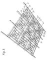
- Figure 1 is a perspective view showing a portion of one embodiment of grid ceiling according to the invention;
- Figure 2 shows, in perspective, first and second grid elements of the ceiling of Figure 1, prior to being assembled; and
- Figure 3 is a view similar to Figure 1, but showing a larger portion of a second embodiment of grid ceiling according to the invention.
- Referring first to Figure 1, there is illustrated therein a presently preferred embodiment of grid ceiling according to the invention. This comprises a support grid comprising a plurality of elongate
first support members 10, having longitudinal parallel axes 11 and a variety of elongatesecond support members 12, the second support members having parallellongitudinal axes 13 angled in the embodiment illustrated at right angles to the axes 11 effective to define therewith the grid with polygonal in this instance, rectangularfirst openings 16 therein. - The
support members lower web 18,side flanges 20 these having inturnedrims 22 at their upper edges. - Mounted within some, or all, of the
openings 16 arefirst grid elements 24 which are each formed of a plurality of first elongate grid members 26 (Figure 2) and secondelongate grid members 28, defining a centralsecond opening 30. Thegrid members support members grid members 26 each have intermediate their ends cutouts extending upwardly from the web portion of thegrid member 26 to about half the height of thegrid member 26 while thesecond grid members 28 have similar, complementary cutouts whereby themembers end portions grid members 26, defined by thenotches 34 at the ends thereof, is chosen to be a close fit between the side walls orflanges 20 of thesupport members 12 so that theunnotched portions 35 thereof rest on therims 22 and prevent the grid moving in that direction. - Similarly the lengths of the
grid members 28 between thenotched portions 36, at the ends thereof, is adapted to the spacing between thesupport members 10 so that theunnotched portions 37 ofgrid members 28 rests on the rims of thesupport members 10. - In a similar way,
second grid elements 40, which are identical, but of smaller dimensions, are mounted in theopenings 30 and define athird opening 42 in which athird grid element 44, again of identical but smaller construction is mounted. This again defines a furthercentral opening 46 in which afurther grid element 48 is mounted. - In the embodiment shown, because of the provision of the
notches 36 in each of the grid members, these notches extending approximately 2/3rds of the way up the length of the associated grid member, each grid element is mounted higher than the support grid, the second grid element is mounted higher than the first grid element and so on. In this way a generally pyramidal structure can be provided. - For internal use, the grid elements may simply be retained in place by gravity. For external use, where the assembly may be subjected to winds and other environmental problems, it may be advantageous for the grid elements to have means positively to retain them in place and for this reason there is illustrated in Figure 2 a
rounded protrusion 50 on the end of each notchedend portion adjacent support member corresponding openings 52 of a surrounding grid element. - In the second embodiment of ceiling shown in Figure 3, like parts have been indicated by like reference numerals. As before, there are a plurality of elongate
first support members 10 and elongatesecond support members 12 defining rectangularfirst openings 16 therein. Mounted within theseopenings 16 arefirst grid elements 24 which are each formed of a plurality of firstelongate grid members 26 and secondelongate grid members 28, in a similar manner to that described above. The second grid elements again define a secondcentral opening 30 in which is mounted, in a similar way,second grid elements 40 which are identical, but of smaller dimensions with thefirst grid elements 24 and define athird opening 42. - At this point, however, there is a variation as compared with that of the first embodiment. In the
third opening 42 is mounted a different form ofthird grid element 60. In this construction thethird grid element 60 consists of a cross-shaped member defined by a firstelongate element 62 and a secondelongate element 64. It will be seen that this gives rather a different visual effect. - At the centre of the grid shown in Figure 3 there is mounted a further possible "third element", namely, a
light fitting 70. It will be appreciated that in a given ceiling several such light fittings could be mounted at appropriate locations. - The structure of the present invention is therefore very well adapted to significant variations to suit the requirements of a particular ceiling designer desiring to give a particular visual and/or lighting effect.
Claims (11)
- A grid ceiling comprising a plurality of elongate first support members (10), said first support members (10) having parallel longitudinal axes (11); a plurality of elongate second support members (12), said second support members (12) having parallel longitudinal axes (13) angled with respect to the longitudinal axes (11) of the first support members (10), to define therewith a grid with polygonal first openings (16) therein; a first grid element (24) inserted in at least one of said first openings (16), the or each first grid element (24) defining therein at least one second opening (30), said first grid element (24) comprising a plurality of elongate grid members (26,28) effective to define said at least one second opening (30), whereby said at least one second opening is of polygonal shape, the first and second support members each being U-profiled sheet metal members, the grid members of the first grid element (24) each having the same or a smaller U-profile cross-section than the support members (10,12), characterised in that, a second smaller grid element (40) is inserted in said at least one second opening (30) of the first grid element (24), or of at least some of the first grid elements, said second grid element (40) comprising means defining a third opening (42).
- A grid ceiling according to claim 1, characterised in that the elongate grid members of said first grid element (24) comprise first grid members (26) and second grid members (28) angled with respect to said first grid members (26).
- A grid ceiling according to claim 1 or 2, characterised in that further elongate grid members of said at least one second grid element (40) are angled with respect to one another and shorter in length than the relevant parallel extending first and second grid members (26,28).
- A grid ceiling according to claim 1, 2 or 3, characterised in that the U-profile sheet metal members have inturned rims (22) at their upper edges and in that the lower portion of each end portion (31,32) of the first grid members (26,28) are notched (34,36), the unnotched portions (35,37) thereof resting on the rims (22) of the support members (10,12) so that when the first grid element (24) is inserted in said first opening (16), the level of the lower web of the first grid members (26,28) is higher than the level of the lower web (18) of the support members (10,12).
- A grid ceiling according to any preceding claim, characterised in that the second grid members of the second grid element (40) have a cross section which is identical to the cross section of the first grid members (26,28), and in that the lower portion of each end portion of the second grid members are notched, the unnotched portions thereof resting on the rims of the first grid members (26,28), so that when the second grid element (40) is inserted in said second opening (30) the level of the lower web of the U-profile second grid members is higher than the level of the U-profile of the lower web (18) of the support members (10, 12).
- A grid ceiling as claimed in any preceding claim, characterised in that said second support members are arranged perpendicular to said first support members whereby said first openings are substantially rectangular.
- A grid ceiling as claimed in any preceding claim, characterised in that said first grid members are arranged perpendicular to one another, whereby said second openings are substantially rectangular.
- A grid ceiling as claimed in any preceding claim, characterised in that said second grid members are arranged substantially perpendicular to each other.
- A grid ceiling as claimed in any preceding claim, and further comprising means defining a third opening (42) in the or each said second grid element (40) and a third grid member (44,60,70) mounted in said third opening (42).
- A grid ceiling as claimed in any preceding claim, and further comprising means defining a third opening in the or each second grid element (40) and a light fitting in at least some of said third openings.
- A grid ceiling according to claim 9, characterised in that said third grid member comprises a cross-shaped member (60) defined by further elongate elements (62,64).
Applications Claiming Priority (2)
| Application Number | Priority Date | Filing Date | Title |
|---|---|---|---|
| US07/574,676 US5174090A (en) | 1990-08-30 | 1990-08-30 | Grid ceiling |
| US574676 | 1990-08-30 |
Publications (2)
| Publication Number | Publication Date |
|---|---|
| EP0476816A1 EP0476816A1 (en) | 1992-03-25 |
| EP0476816B1 true EP0476816B1 (en) | 1995-12-06 |
Family
ID=24297150
Family Applications (1)
| Application Number | Title | Priority Date | Filing Date |
|---|---|---|---|
| EP91307067A Expired - Lifetime EP0476816B1 (en) | 1990-08-30 | 1991-08-01 | Grid ceiling |
Country Status (5)
| Country | Link |
|---|---|
| US (1) | US5174090A (en) |
| EP (1) | EP0476816B1 (en) |
| BR (1) | BR9103718A (en) |
| CA (1) | CA2050231C (en) |
| DE (1) | DE69115196T2 (en) |
Families Citing this family (9)
| Publication number | Priority date | Publication date | Assignee | Title |
|---|---|---|---|---|
| DE4238352C1 (en) * | 1992-11-13 | 1994-02-17 | Freudenberg Carl Fa | Air silencer |
| USD373831S (en) | 1995-03-16 | 1996-09-17 | Blockbuster Entertainment Inc. | Ceiling |
| US20030127637A1 (en) * | 2002-01-04 | 2003-07-10 | Douglas Fenwick | Large offset lattice fence |
| USD538449S1 (en) * | 2005-01-18 | 2007-03-13 | Usg Interiors, Inc. | Large wave wire form ceiling panel |
| USD519220S1 (en) * | 2005-01-18 | 2006-04-18 | Usg Interiors, Inc. | Wire weave ceiling panel |
| USD512521S1 (en) * | 2005-01-18 | 2005-12-06 | Usg Interiors, Inc. | Wire formed ceiling panel |
| USD521658S1 (en) * | 2005-01-18 | 2006-05-23 | Usg Interiors, Inc. | Small wave wire form ceiling panel |
| US10447040B2 (en) | 2014-10-15 | 2019-10-15 | Cummins Power Generation Ip, Inc. | Programmable inverter for controllable grid response |
| US10407904B2 (en) * | 2017-06-12 | 2019-09-10 | Turf Design, Inc. | Apparatus and system for dynamic ceiling system and methods thereof |
Family Cites Families (11)
| Publication number | Priority date | Publication date | Assignee | Title |
|---|---|---|---|---|
| US2710679A (en) * | 1950-10-24 | 1955-06-14 | John T Bibb | Suspended ceiling construction |
| US3003055A (en) * | 1958-09-10 | 1961-10-03 | Liberman Milton | Lighting fixture |
| US3777432A (en) * | 1972-09-18 | 1973-12-11 | Lightolier Inc | Collapsibly joined louver grid |
| FR2523625A1 (en) * | 1982-03-17 | 1983-09-23 | Tiaso | Cellular frame for building industry - has right angle sets of aluminium blades with interlocking notches |
| GB2122666A (en) * | 1982-06-21 | 1984-01-18 | Intalite International Nv | Suspended ceiling |
| CA1209770A (en) * | 1982-12-17 | 1986-08-19 | Robert C. Heritage | Openwork screen assembly |
| US4665674A (en) * | 1985-04-11 | 1987-05-19 | Hunter Douglas International N.V. | Grid ceiling |
| GB8509345D0 (en) * | 1985-04-11 | 1985-05-15 | Hunter Douglas Ind Bv | Grid ceiling |
| DE3526740C1 (en) * | 1985-07-26 | 1986-11-27 | Durlum-Leuchten Gmbh Lichttechnische Spezialfabrik, 7860 Schopfheim | Lattice-like ceiling |
| US4738066A (en) * | 1985-11-08 | 1988-04-19 | Woodtech, Inc. | Decorative ceiling system |
| US4951443A (en) * | 1989-06-06 | 1990-08-28 | Ecolite Manufacturing Co. | Ceiling panel and T-rail mounting assembly |
-
1990
- 1990-08-30 US US07/574,676 patent/US5174090A/en not_active Expired - Lifetime
-
1991
- 1991-08-01 DE DE69115196T patent/DE69115196T2/en not_active Expired - Fee Related
- 1991-08-01 EP EP91307067A patent/EP0476816B1/en not_active Expired - Lifetime
- 1991-08-29 CA CA002050231A patent/CA2050231C/en not_active Expired - Fee Related
- 1991-08-29 BR BR919103718A patent/BR9103718A/en active Search and Examination
Also Published As
| Publication number | Publication date |
|---|---|
| CA2050231A1 (en) | 1992-03-01 |
| CA2050231C (en) | 1995-07-04 |
| DE69115196D1 (en) | 1996-01-18 |
| US5174090A (en) | 1992-12-29 |
| BR9103718A (en) | 1992-05-19 |
| DE69115196T2 (en) | 1996-05-02 |
| EP0476816A1 (en) | 1992-03-25 |
Similar Documents
| Publication | Publication Date | Title |
|---|---|---|
| CA2050231C (en) | Grid ceiling | |
| US4613929A (en) | Retrofit louvre for lighting fixture | |
| GB2089016A (en) | Integrated lighting systems for suspended ceilings | |
| US4679375A (en) | Suspension ceiling grid system with narrow-faced grid | |
| KR102193750B1 (en) | One touch type cable tray | |
| US20050063775A1 (en) | Connection splice plate for connecting two portions of a wire cable tray, wire cable tray equipped with same and wire cable tray having two portions connected with such a splice plate | |
| MXPA01013144A (en) | Accessory for fixing a wire cable tray, and wire cable tray equipped with at least such an accessory. | |
| GB2204923A (en) | Plastics closure member | |
| WO1996017143A1 (en) | Supporting member for lattice structures | |
| GB2080356A (en) | Panelling and carriers therefor | |
| US3665837A (en) | Lineal air diffuser bar | |
| WO2001045221A1 (en) | Cable support apparatus | |
| US6570092B2 (en) | High-strength wire cable duct | |
| US5203818A (en) | Suspension hook | |
| US6669175B2 (en) | Tile type fencing insert | |
| EP1036241B1 (en) | Cladding panels of sheet metal or similar material for forming a coffered ceiling and a method for assembling of such panels | |
| EP0113987A2 (en) | Openwork screen assembly | |
| EP1475871B1 (en) | Bracket unit for supporting cable-carrier systems in industrial ductings | |
| AU744265B2 (en) | Quiet rotor blade and wind energy installation equipped with rotor blades of this type | |
| HUP0103351A2 (en) | Metal channel for securing studs for wall panels | |
| WO2001065656A1 (en) | Vented pedestal for electronics housing | |
| EP0553880A2 (en) | Hanger for outdoor heat exchanger | |
| EP3581727B1 (en) | Cladding system including a flexible grid and panels | |
| EP2149952A1 (en) | Plural electrical mechanism carrier | |
| EP1143205B1 (en) | Air conditioner |
Legal Events
| Date | Code | Title | Description |
|---|---|---|---|
| PUAI | Public reference made under article 153(3) epc to a published international application that has entered the european phase |
Free format text: ORIGINAL CODE: 0009012 |
|
| AK | Designated contracting states |
Kind code of ref document: A1 Designated state(s): BE CH DE DK ES FR GB IT LI NL SE |
|
| 17P | Request for examination filed |
Effective date: 19920904 |
|
| 17Q | First examination report despatched |
Effective date: 19930929 |
|
| GRAA | (expected) grant |
Free format text: ORIGINAL CODE: 0009210 |
|
| AK | Designated contracting states |
Kind code of ref document: B1 Designated state(s): BE CH DE DK ES FR GB IT LI NL SE |
|
| PG25 | Lapsed in a contracting state [announced via postgrant information from national office to epo] |
Ref country code: ES Free format text: THE PATENT HAS BEEN ANNULLED BY A DECISION OF A NATIONAL AUTHORITY Effective date: 19951206 Ref country code: DK Effective date: 19951206 |
|
| REF | Corresponds to: |
Ref document number: 69115196 Country of ref document: DE Date of ref document: 19960118 |
|
| ET | Fr: translation filed | ||
| REG | Reference to a national code |
Ref country code: CH Ref legal event code: NV Representative=s name: ROTTMANN, ZIMMERMANN + PARTNER AG |
|
| ITF | It: translation for a ep patent filed | ||
| PG25 | Lapsed in a contracting state [announced via postgrant information from national office to epo] |
Ref country code: SE Effective date: 19960306 |
|
| PG25 | Lapsed in a contracting state [announced via postgrant information from national office to epo] |
Ref country code: GB Effective date: 19960801 |
|
| PG25 | Lapsed in a contracting state [announced via postgrant information from national office to epo] |
Ref country code: LI Effective date: 19960831 Ref country code: CH Effective date: 19960831 Ref country code: BE Effective date: 19960831 |
|
| PLBE | No opposition filed within time limit |
Free format text: ORIGINAL CODE: 0009261 |
|
| STAA | Information on the status of an ep patent application or granted ep patent |
Free format text: STATUS: NO OPPOSITION FILED WITHIN TIME LIMIT |
|
| 26N | No opposition filed | ||
| BERE | Be: lapsed |
Owner name: HUNTER DOUGLAS INTERNATIONAL N.V. Effective date: 19960831 |
|
| PG25 | Lapsed in a contracting state [announced via postgrant information from national office to epo] |
Ref country code: NL Effective date: 19970301 |
|
| GBPC | Gb: european patent ceased through non-payment of renewal fee |
Effective date: 19960801 |
|
| REG | Reference to a national code |
Ref country code: CH Ref legal event code: PL |
|
| PG25 | Lapsed in a contracting state [announced via postgrant information from national office to epo] |
Ref country code: FR Effective date: 19970430 |
|
| NLV4 | Nl: lapsed or anulled due to non-payment of the annual fee |
Effective date: 19970301 |
|
| PG25 | Lapsed in a contracting state [announced via postgrant information from national office to epo] |
Ref country code: DE Effective date: 19970501 |
|
| REG | Reference to a national code |
Ref country code: FR Ref legal event code: ST |
|
| PG25 | Lapsed in a contracting state [announced via postgrant information from national office to epo] |
Ref country code: IT Free format text: LAPSE BECAUSE OF NON-PAYMENT OF DUE FEES Effective date: 20050801 |