EP0476740A1 - Bipolar battery and assembly method - Google Patents
Bipolar battery and assembly method Download PDFInfo
- Publication number
- EP0476740A1 EP0476740A1 EP91202215A EP91202215A EP0476740A1 EP 0476740 A1 EP0476740 A1 EP 0476740A1 EP 91202215 A EP91202215 A EP 91202215A EP 91202215 A EP91202215 A EP 91202215A EP 0476740 A1 EP0476740 A1 EP 0476740A1
- Authority
- EP
- European Patent Office
- Prior art keywords
- cell
- opening
- collars
- pockets
- compartments
- Prior art date
- Legal status (The legal status is an assumption and is not a legal conclusion. Google has not performed a legal analysis and makes no representation as to the accuracy of the status listed.)
- Withdrawn
Links
- 238000000034 method Methods 0.000 title claims description 6
- 239000000565 sealant Substances 0.000 claims abstract description 39
- 238000004519 manufacturing process Methods 0.000 claims abstract description 10
- 238000005304 joining Methods 0.000 claims abstract description 4
- 238000005192 partition Methods 0.000 claims description 25
- 239000003792 electrolyte Substances 0.000 claims description 12
- -1 polypropylene Polymers 0.000 claims description 11
- 238000003860 storage Methods 0.000 claims description 9
- 229920000098 polyolefin Polymers 0.000 claims description 7
- 238000007789 sealing Methods 0.000 claims description 7
- 239000004743 Polypropylene Substances 0.000 claims description 6
- 229920001155 polypropylene Polymers 0.000 claims description 6
- 230000004888 barrier function Effects 0.000 claims description 4
- 229920001169 thermoplastic Polymers 0.000 claims description 4
- 239000004416 thermosoftening plastic Substances 0.000 claims description 4
- 229920001971 elastomer Polymers 0.000 claims description 3
- 239000000806 elastomer Substances 0.000 claims description 3
- 229920001748 polybutylene Polymers 0.000 claims description 3
- 230000008878 coupling Effects 0.000 claims 2
- 238000010168 coupling process Methods 0.000 claims 2
- 238000005859 coupling reaction Methods 0.000 claims 2
- 239000011262 electrochemically active material Substances 0.000 description 5
- 238000002347 injection Methods 0.000 description 5
- 239000007924 injection Substances 0.000 description 5
- 239000000463 material Substances 0.000 description 5
- 239000007788 liquid Substances 0.000 description 4
- 239000000758 substrate Substances 0.000 description 4
- 239000004604 Blowing Agent Substances 0.000 description 3
- QVGXLLKOCUKJST-UHFFFAOYSA-N atomic oxygen Chemical compound [O] QVGXLLKOCUKJST-UHFFFAOYSA-N 0.000 description 3
- 239000011521 glass Substances 0.000 description 3
- 239000001301 oxygen Substances 0.000 description 3
- 229910052760 oxygen Inorganic materials 0.000 description 3
- 239000002253 acid Substances 0.000 description 2
- 239000011347 resin Substances 0.000 description 2
- 229920005989 resin Polymers 0.000 description 2
- 229920002379 silicone rubber Polymers 0.000 description 2
- UFHFLCQGNIYNRP-UHFFFAOYSA-N Hydrogen Chemical compound [H][H] UFHFLCQGNIYNRP-UHFFFAOYSA-N 0.000 description 1
- 229920001410 Microfiber Polymers 0.000 description 1
- 239000004698 Polyethylene Substances 0.000 description 1
- 239000002250 absorbent Substances 0.000 description 1
- 239000004063 acid-resistant material Substances 0.000 description 1
- 239000000853 adhesive Substances 0.000 description 1
- 230000001070 adhesive effect Effects 0.000 description 1
- 230000015572 biosynthetic process Effects 0.000 description 1
- 239000013536 elastomeric material Substances 0.000 description 1
- 239000003822 epoxy resin Substances 0.000 description 1
- 239000007789 gas Substances 0.000 description 1
- 239000003365 glass fiber Substances 0.000 description 1
- 239000001257 hydrogen Substances 0.000 description 1
- 229910052739 hydrogen Inorganic materials 0.000 description 1
- 230000003100 immobilizing effect Effects 0.000 description 1
- 239000003658 microfiber Substances 0.000 description 1
- 229920000647 polyepoxide Polymers 0.000 description 1
- 229920000573 polyethylene Polymers 0.000 description 1
- 229920000642 polymer Polymers 0.000 description 1
- 239000011148 porous material Substances 0.000 description 1
- 239000004945 silicone rubber Substances 0.000 description 1
- 238000007711 solidification Methods 0.000 description 1
- 230000008023 solidification Effects 0.000 description 1
Images

Classifications
-
- H—ELECTRICITY
- H01—ELECTRIC ELEMENTS
- H01M—PROCESSES OR MEANS, e.g. BATTERIES, FOR THE DIRECT CONVERSION OF CHEMICAL ENERGY INTO ELECTRICAL ENERGY
- H01M10/00—Secondary cells; Manufacture thereof
- H01M10/04—Construction or manufacture in general
- H01M10/0413—Large-sized flat cells or batteries for motive or stationary systems with plate-like electrodes
-
- H—ELECTRICITY
- H01—ELECTRIC ELEMENTS
- H01M—PROCESSES OR MEANS, e.g. BATTERIES, FOR THE DIRECT CONVERSION OF CHEMICAL ENERGY INTO ELECTRICAL ENERGY
- H01M10/00—Secondary cells; Manufacture thereof
- H01M10/04—Construction or manufacture in general
- H01M10/0413—Large-sized flat cells or batteries for motive or stationary systems with plate-like electrodes
- H01M10/0418—Large-sized flat cells or batteries for motive or stationary systems with plate-like electrodes with bipolar electrodes
-
- H—ELECTRICITY
- H01—ELECTRIC ELEMENTS
- H01M—PROCESSES OR MEANS, e.g. BATTERIES, FOR THE DIRECT CONVERSION OF CHEMICAL ENERGY INTO ELECTRICAL ENERGY
- H01M10/00—Secondary cells; Manufacture thereof
- H01M10/04—Construction or manufacture in general
- H01M10/0463—Cells or batteries with horizontal or inclined electrodes
-
- H—ELECTRICITY
- H01—ELECTRIC ELEMENTS
- H01M—PROCESSES OR MEANS, e.g. BATTERIES, FOR THE DIRECT CONVERSION OF CHEMICAL ENERGY INTO ELECTRICAL ENERGY
- H01M10/00—Secondary cells; Manufacture thereof
- H01M10/06—Lead-acid accumulators
- H01M10/18—Lead-acid accumulators with bipolar electrodes
-
- H—ELECTRICITY
- H01—ELECTRIC ELEMENTS
- H01M—PROCESSES OR MEANS, e.g. BATTERIES, FOR THE DIRECT CONVERSION OF CHEMICAL ENERGY INTO ELECTRICAL ENERGY
- H01M50/00—Constructional details or processes of manufacture of the non-active parts of electrochemical cells other than fuel cells, e.g. hybrid cells
- H01M50/50—Current conducting connections for cells or batteries
- H01M50/528—Fixed electrical connections, i.e. not intended for disconnection
- H01M50/529—Intercell connections through partitions, e.g. in a battery casing
-
- Y—GENERAL TAGGING OF NEW TECHNOLOGICAL DEVELOPMENTS; GENERAL TAGGING OF CROSS-SECTIONAL TECHNOLOGIES SPANNING OVER SEVERAL SECTIONS OF THE IPC; TECHNICAL SUBJECTS COVERED BY FORMER USPC CROSS-REFERENCE ART COLLECTIONS [XRACs] AND DIGESTS
- Y02—TECHNOLOGIES OR APPLICATIONS FOR MITIGATION OR ADAPTATION AGAINST CLIMATE CHANGE
- Y02E—REDUCTION OF GREENHOUSE GAS [GHG] EMISSIONS, RELATED TO ENERGY GENERATION, TRANSMISSION OR DISTRIBUTION
- Y02E60/00—Enabling technologies; Technologies with a potential or indirect contribution to GHG emissions mitigation
- Y02E60/10—Energy storage using batteries
-
- Y—GENERAL TAGGING OF NEW TECHNOLOGICAL DEVELOPMENTS; GENERAL TAGGING OF CROSS-SECTIONAL TECHNOLOGIES SPANNING OVER SEVERAL SECTIONS OF THE IPC; TECHNICAL SUBJECTS COVERED BY FORMER USPC CROSS-REFERENCE ART COLLECTIONS [XRACs] AND DIGESTS
- Y02—TECHNOLOGIES OR APPLICATIONS FOR MITIGATION OR ADAPTATION AGAINST CLIMATE CHANGE
- Y02P—CLIMATE CHANGE MITIGATION TECHNOLOGIES IN THE PRODUCTION OR PROCESSING OF GOODS
- Y02P70/00—Climate change mitigation technologies in the production process for final industrial or consumer products
- Y02P70/50—Manufacturing or production processes characterised by the final manufactured product
-
- Y—GENERAL TAGGING OF NEW TECHNOLOGICAL DEVELOPMENTS; GENERAL TAGGING OF CROSS-SECTIONAL TECHNOLOGIES SPANNING OVER SEVERAL SECTIONS OF THE IPC; TECHNICAL SUBJECTS COVERED BY FORMER USPC CROSS-REFERENCE ART COLLECTIONS [XRACs] AND DIGESTS
- Y10—TECHNICAL SUBJECTS COVERED BY FORMER USPC
- Y10T—TECHNICAL SUBJECTS COVERED BY FORMER US CLASSIFICATION
- Y10T29/00—Metal working
- Y10T29/49—Method of mechanical manufacture
- Y10T29/49002—Electrical device making
- Y10T29/49108—Electric battery cell making
- Y10T29/4911—Electric battery cell making including sealing
Definitions
- This invention relates to multi-cell, bipolar batteries and a method of making same, and more particularly to means/method for preventing electrolyte leakage between adjacent cells thereof as specified in the preamble of claim 1, for example as disclosed in US-A-3,692,587.
- Bipolar batteries employ either one of two general types of bipolar electrodes.
- the first, or "face-to-face” type of bipolar electrode utilizes an electrolyte-impervious, conductive sheet having a first polarity, electrochemically-active material applied (e.g., pasted) onto one face of the sheet and an opposite-polarity, electrochemically-active material applied to the opposite face of the sheet.
- These electrodes are stacked in the battery such that the opposite-polarity faces of adjacent electrodes oppose each other across an electrolyte-filled gap, and are separated one from the other by an electrolyte-permeable separator.
- the second, or "side-by-side”, type of bipolar electrode comprises an electrically-conductive substrate (e.g., a grid-work of conductive wires) having two separate, substantially co-planar, side-by-side electrode portions (hereafter termed "plates") thereon, each of which contains an electrochemically-active material of opposite polarity to the other.
- the two opposite-polarity plates are electrically connected to each other by an electrically-conductive link which comprises a central segment of the shared conductive substrate which is free of electrochemically-active material and lies intermediate the two opposite-polarity plates and in essentially the same plane as the plates.
- the side-by-side bipolar electrodes disclosed in US-A-3,167,456 are arranged in overlapping fashion so as to form a plurality of cell elements, each housed in a separate cell compartment of a container and comprising a stack of the positive and negative polarity plates of different bipolar electrodes alternately interleaved one with the other.
- the bipolar electrodes are arranged such that the first polarity plate of each bipolar electrode resides in one compartment and the opposite polarity plate of the same bipolar electrode resides in an adjacent cell compartment in the fashion depicted in Figure 1 of the accompanying drawings hereof.
- the electrochemically-neutral centre segment of the conductive grid disclosed in US-A-3,167,456 electrically links the opposite polarity plates together from one cell to the next. Several such links stacked together between adjacent compartments form an intercell connector of the battery and serve to electrically series-connect the several cell elements together.
- the present invention relates to improvements to multi-cell bipolar batteries of the type disclosed using "side-by-side” bipolar electrodes as applied to secondary batteries and particularly re-combinant Pb-acid batteries. It is an object of the present invention to provide secondary, multi-cell, bipolar batteries of the type disclosed in US-A-3,167,456 with an improved electrolyte barrier between adjacent cell compartments, and a method of making same, which substantially prevents electrolyte leakage between adjacent cells thereby preventing self-discharge and increasing both the shelf and operating lives of the battery.
- a method of making a multi-cell electric storage battery according to the present invention is characterised by the features specified in the characterising portion of claim 1.
- the invention comprehends a multi-cell electric storage battery, and method of making same, and more particularly a means/method for preventing leakage of electrolyte between adjacent cell compartments in secondary batteries of the type disclosed in US-A-3,167,456 having side-by-side bipolar electrodes.
- the battery will preferably be a gas re-combinant Pb-acid battery wherein oxygen generated at one plate moves across the inter-electrode gap through a fibrous mat to an opposite polarity plate and re-combines with hydrogen generated thereat.
- the battery comprises a container having a plurality of walls defining a plurality of individual cell compartments wherein one of the walls is an intercell partition separating one cell compartment from the next.
- the partition includes a section, preferably near the centre thereof, which is thicker than the remainder of the partition and is adapted to receive an intercell connector of the battery.
- a galvanic cell element is positioned in each of the cell compartments and comprises a stack of positive and negative polarity plates alternately interleaved one with the other and separated one from the other by an electrolyte-permeable separator.
- a passage opening is provided through the thicker section of the partition through which the cell elements in adjacent compartments are electrically connected, which opening is flanked by a pair of pockets formed in the thick section and having mouths confronting the opening.
- a unique means/method for substantially isolating adjacent cell compartments one from the other so as to substantially prevent electrolyte leakage therebetween via the intercell connector passage is provided.
- intercell connector means are provided for electrically series-connecting adjacent cell elements together through the opening between adjacent cell compartments, which intercell connector means comprises a plurality of electrically-conductive links stacked in the opening between the compartments wherein each link joins a pair of co-planar opposite-polarity plates into a side-by-side bipolar electrode.
- the several bipolar electrodes are arranged and positioned in the container in a similar manner as is disclosed in US-A-3,167,456, such that the conductive link joining the opposite-polarity plates of each bipolar electrode is substantially aligned with other similar links for other such electrodes within the opening in the intercell partition between the compartments.
- the intercell connector will preferably include a border extending along the edge of each plate adjacent the opening in the intercell partition for collecting current from the plate and conducting it to the link.
- Each link has an elastomeric collar closely fitted thereabout.
- the collar is aligned and stacked with similar collars on other links in the opening and together therewith substantially fills the opening in the partition.
- the height of the stacked collars exceeds the depth of the opening (i.e., top to bottom) such that, when a cover is placed on the container, the stack of collars are longitudinally compressed causing them to deform laterally and seal the mouths of the pockets flanking the opening closed. Thereafter sealant is injected through apertures in the cover into the pockets flanking the opening under sufficient pressure as to laterally hydraulically compress the collars.
- the collar comprises a central portion engaging the link and otherwise substantially filling the cross-section of the opening and having a pair of laterally-projecting wings extending into the pockets flanking the opening. Injection of the sealant causes the wings to deform into tight, sealing engagement with the sidewalls of the pocket.
- the distal ends of the wing portions are bi-furcated so as to provide a pair of pronged branches which lie contiguous the sidewalls defining the pocket. Injection of the sealant presses the branches into sealing engagement with the sidewalls of the pocket.
- the bipolar electrodes are alternately stacked in the container in such a manner as to: (1) constitute the individual cell element stacks; (2) align the intercell connector links one with the other in the opening; and (3) cause the collars on each bipolar electrode to be aligned and to abut one another in the opening in the partition.
- a cover is positioned thereon so as to longitudinally compress the collars sufficiently to laterally expand them so as to plug the mouths of the pockets and thus prevent escape of sealant therefrom.
- the cover has apertures thereon aligned with the pockets.
- Liquid sealant e.g., an uncured thermo-setting resin or a heated thermo-plastic resin capable of bonding to the pocket sidewalls and the collar
- the collars will preferably comprise a polyolefin-based thermo-plastic elastomer such as Santoprene RTM or Kraton RTM available commercially from Monsanto Chemical Co. or Shell Chemical Co., respectively.
- the sealant will preferably comprise a high-melt-flow polypropylene or polybutylene which bonds well with the polypropylene container and the polyolefin-based collar material.
- uncured epoxy resin may be injected into the pockets which, upon hardening, bonds to the pocket sidewalls as well as to the collars. Silicone rubber may also be used.
- the sealant will preferably be auto-expandable (e.g., include a blowing agent) for causing the sealant to swell within the pockets after it is injected therein to more effectively fill any voids therein and exert compressive force on the elastomeric collars.
- the bipolar battery of the present invention will preferably be of the so-called gas-re-combinant type wherein a bibulous, fibrous mat is positioned between the plates on both sides of the opening for absorbing and substantially immobilizing electrolyte of the battery whilst permitting oxygen transport between adjacent plates in the same element.
- the mat will preferably comprise glass microfibres such as are well known in the art for use in gas-re-combinant batteries.
- One such glass mat material is commercially available in a variety of grades from the Hollingsworth & Vose Company under the trade name Hovosorb RTM .
- other fibrous mats made from polyolefins or other polymer fibres effective to immobilize the electrolyte and permit oxygen transport therethrough are also useful.
- Dynel RTM or polypropylene mat useful for this purpose is described in US-A-3,553,020.
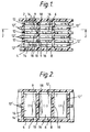
- FIGS 1 and 2 illustrate a multi-cell bipolar battery of the side-by-side bipolar electrode type having a first cell element 2 in container compartment 4, a second cell element 6 in container compartment 8 and an intercell partition 10 separating the compartments 4 and 8 each from the other.
- Bipolar electrodes 12 comprise a negative polarity plate portion 14 and a positive polarity plate portion 16 each in separate compartments 4 and 8 respectively of the container and electrically joined one to the other by an electrically-conductive link 18 sealingly passing through opening 9 in the partition 10.
- the bipolar electrodes 12 are interleaved with similar electrodes 12' which are alternately oriented 180° to each other such that in each cell element the negative plate portion of one bipolar electrode lies face-to-face with the positive plate portion of an adjacent bipolar electrode.
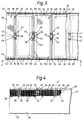
- Figures 3, 4 and 9 show a container 20 comprising a bottom wall 22, side walls 24 and 26 and having a cover 28 which forms the top wall of the container 20.
- the container 20 defines a plurality of compartments 30 each adapted to receive an individual cell element 32 and separated one from the other by an intercell partition 34.
- the partition 34 includes a thickened section 35 having pockets 36 therein flanking an intercell opening 42 and defined by opposing sidewalls 38.
- the pockets 36 have mouths 40 confronting the opening 42 lying therebetween.
- Ribs 44 extend along the bottom wall 22 and support the element 32 off the floor of the container.
- the cover 28 is adapted to mate with shoulders 46 formed on the walls 24 and 26 of container 20 and is bonded thereto as by heat-sealing, adhesives or otherwise.
- the cover 28 includes a plurality of holes 47 therethrough which are aligned with the pockets 36 in the thickened partition section 35 to permit injection of sealant therein after the cover 28 has been placed on, and sealed to, the container 20.
- a bipolar electrode 48 has a positive plate portion 50 and a negative plate portion 52 electrically interconnected one to the other by an electrically-conductive link 54. More specifically, the bipolar electrode 48 includes a common conductive substrate comprising grid-wires 56 and pasted with electrochemically-active material 58.
- the positive plate 50 of the bipolar electrode 48 is sheathed in an envelope 60 of microporous battery separator material (e.g., microporous polyethylene) and the respective electrodes 50 and 52, in a given stack thereof, are separated one from the other by a bibulous electrolyte-absorbent, fibrous mat (not shown) formed from an acid-resistant material such as, for example, glass, and which is commonly found in gas-re-combinant type batteries.
- microporous battery separator material e.g., microporous polyethylene
- Each bipolar electrode 48 shares a common conductive substrate comprising a plurality of interconnecting grid-wires 56 extending from a current-collecting border 62 on the positive plate side and grid wires 56' extending from a current-collecting border 64 on the negative plate side of the bipolar electrode 48.
- the link 54 joins the respective current collecting borders 62 and 64.
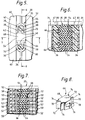
- An elastomeric collar 66 (see Figure 8) is positioned snugly about each link 54 and is adapted to fit within the opening 42 in the thickened section 35 of the partition 34.
- the collar 66 will preferably comprise a centre portion 68 which substantially fills the opening 42 and a pair of laterally-extending wing portions 70 projecting outwardly from the centre portion 68 and adapted to fit within the opposing pockets 36 as best shown in Figures 5-7.
- the distal ends 72 of the wings 70 are each bi-furcated so as to provide a pair of prongs 74 adapted to lie adjacent the sidewalls 38 defining the pockets 36 as will be discussed in more detail hereinafter.
- the centre portion 68 includes an opening 76 therethrough sized to snugly receive a link 54, and is split open at a cut 78 to permit positioning of the collar 66 onto the link 54.
- the collar preferably comprises a polyolefin-based thermo-plastic elastomer (e.g., Santoprene RTM or Kraton RTM ) which bonds well to the sealant with which it subsequently comes into contact.
- the respective bipolar electrodes 48 are stacked (see Figure 9) in the battery container in the manner described in connection with Figures 1 and 2 and such that the collars 66 on adjacent bipolar electrode links 54 abut one another in the opening 42 so as to space the respective bipolar electrodes 48 apart and to provide a barrier to the outflow of sealant injected into the pockets 36 flanking the collars 66.
- the centre portions 68 of the respective collars 66 substantially fill the cross-section of the opening 42 and the wings extend into the mouths 40 of the flanking pockets 36.
- the height of the column of collars is initially somewhat higher than the height of the opening 36, and the application of longitudinal force to the column causes the stack to compress and expand laterally into tight engagement with the mouths 40 of the pockets sufficient to prevent leakage of sealant from the pockets 36 during subsequent injection of sealant thereinto.
- the cover 28 is pressed onto the container 20 so as to longitudinally compress the collars 66 and laterally expand them so as to plug the mouths 40 of the pockets 36.
- Liquid sealant 80 is then injected into the pockets 36 through the apertures 47 provided in the cover 28.
- the liquid sealant will preferably comprise a high-melt-flow polypropylene or polybutylene for bonding to both the collar and the sidewalls 38.
- the sealant may remain flexible throughout its life and accordingly may comprise an electrolyte-resistant elastomeric material such as silicon rubber which is injected into the opening as a liquid before curing to an elastic state.
- the sealant may also include a blowing agent or the like which causes the sealant to swell or expand after injection so as to ensure complete filling of the region between the bars and the recesses at the ends of the opening.
- a blowing agent or the like which causes the sealant to swell or expand after injection so as to ensure complete filling of the region between the bars and the recesses at the ends of the opening.
- blowing agents result in the formation of a porous sealant characterized by a multitude of small closed-cell pores distributed throughout.
- the sealant is injected into the pockets 36 under sufficient pressure to further compress the wing portions 70 and expand them laterally into tight engagement with the sidewalls 38. At the same time the sealant spreads the prongs 74 apart and presses them tightly against the sidewalls 38.
- the sealant 80 is preferably injected into the pockets 36 after the cover 28 has been secured to the container 20 and by inserting a nozzle(s) (not shown) through the holes 47 in the cover 28 and down to near the bottom wall 22 of the container 20. At that time, the sealant is injected into the pocket(s) 36 and the nozzle(s) are slowly withdrawn from the pocket(s) at a rate commensurate with the rate at which the sealant is dispensed into the pocket(s) and so that all air is displaced from the pocket(s) ahead of the moving front of sealant and out through the holes 47 in the cover 28.
- the sealant can be injected directly through the apertures 47.
- the sealant will preferably comprise a hardenable, high-strength material (e.g., high-melt-flow polyolefin) which, upon solidification, further serves to anchor the cover 28 in place.
- a hardenable, high-strength material e.g., high-melt-flow polyolefin
- the microporous separator 60 sheathes the positive plate 50 of each bipolar electrode 48 and takes the form of an envelope formed by folding a sheet of the separator material along a centreline 82 thereof (see Figures 4 and 9) and bonding (e.g., heat-sealing) lateral edges 84 and 86 of the envelope to themselves outwards of the edges of the plate 50.
- the plates will preferably be separated one from the other by said fibrous mat in the form of a porous fibrous glass mat which absorbs the electrolyte while still permitting O2 transport thereacross to the opposite electrode for reaction thereat and so as to provide a gas-re-combinant battery.
Landscapes
- Chemical & Material Sciences (AREA)
- Chemical Kinetics & Catalysis (AREA)
- Electrochemistry (AREA)
- General Chemical & Material Sciences (AREA)
- Engineering & Computer Science (AREA)
- Manufacturing & Machinery (AREA)
- Secondary Cells (AREA)
Abstract
The specification discloses a bipolar battery and a method of making intercell connections between adjacent cells involving use of an elastomeric collar (66) on respective links (54) joining bipolar electrode halves (50,52), compressing the collars (66) in an opening (42) between adjacent cell compartments (30), and injecting a sealant (80) about the collars (66) to seal-off the opening (42).
Description
- This invention relates to multi-cell, bipolar batteries and a method of making same, and more particularly to means/method for preventing electrolyte leakage between adjacent cells thereof as specified in the preamble of claim 1, for example as disclosed in US-A-3,692,587.
- Bipolar batteries employ either one of two general types of bipolar electrodes. The first, or "face-to-face" type of bipolar electrode, utilizes an electrolyte-impervious, conductive sheet having a first polarity, electrochemically-active material applied (e.g., pasted) onto one face of the sheet and an opposite-polarity, electrochemically-active material applied to the opposite face of the sheet. These electrodes are stacked in the battery such that the opposite-polarity faces of adjacent electrodes oppose each other across an electrolyte-filled gap, and are separated one from the other by an electrolyte-permeable separator. The second, or "side-by-side", type of bipolar electrode comprises an electrically-conductive substrate (e.g., a grid-work of conductive wires) having two separate, substantially co-planar, side-by-side electrode portions (hereafter termed "plates") thereon, each of which contains an electrochemically-active material of opposite polarity to the other. The two opposite-polarity plates are electrically connected to each other by an electrically-conductive link which comprises a central segment of the shared conductive substrate which is free of electrochemically-active material and lies intermediate the two opposite-polarity plates and in essentially the same plane as the plates. Such side-by-side bipolar electrodes, and a multi-cell primary battery made therefrom, are described in US-A-3,167,456. The side-by-side bipolar electrodes disclosed in US-A-3,167,456 are arranged in overlapping fashion so as to form a plurality of cell elements, each housed in a separate cell compartment of a container and comprising a stack of the positive and negative polarity plates of different bipolar electrodes alternately interleaved one with the other. The bipolar electrodes are arranged such that the first polarity plate of each bipolar electrode resides in one compartment and the opposite polarity plate of the same bipolar electrode resides in an adjacent cell compartment in the fashion depicted in Figure 1 of the accompanying drawings hereof. The electrochemically-neutral centre segment of the conductive grid disclosed in US-A-3,167,456 electrically links the opposite polarity plates together from one cell to the next. Several such links stacked together between adjacent compartments form an intercell connector of the battery and serve to electrically series-connect the several cell elements together.
- The present invention relates to improvements to multi-cell bipolar batteries of the type disclosed using "side-by-side" bipolar electrodes as applied to secondary batteries and particularly re-combinant Pb-acid batteries. It is an object of the present invention to provide secondary, multi-cell, bipolar batteries of the type disclosed in US-A-3,167,456 with an improved electrolyte barrier between adjacent cell compartments, and a method of making same, which substantially prevents electrolyte leakage between adjacent cells thereby preventing self-discharge and increasing both the shelf and operating lives of the battery. This and other objects and advantages of the present invention will become more apparent from the description thereof which follows.
- A method of making a multi-cell electric storage battery according to the present invention is characterised by the features specified in the characterising portion of claim 1.
- The invention comprehends a multi-cell electric storage battery, and method of making same, and more particularly a means/method for preventing leakage of electrolyte between adjacent cell compartments in secondary batteries of the type disclosed in US-A-3,167,456 having side-by-side bipolar electrodes. The battery will preferably be a gas re-combinant Pb-acid battery wherein oxygen generated at one plate moves across the inter-electrode gap through a fibrous mat to an opposite polarity plate and re-combines with hydrogen generated thereat. The battery comprises a container having a plurality of walls defining a plurality of individual cell compartments wherein one of the walls is an intercell partition separating one cell compartment from the next. The partition includes a section, preferably near the centre thereof, which is thicker than the remainder of the partition and is adapted to receive an intercell connector of the battery. A galvanic cell element is positioned in each of the cell compartments and comprises a stack of positive and negative polarity plates alternately interleaved one with the other and separated one from the other by an electrolyte-permeable separator. A passage opening is provided through the thicker section of the partition through which the cell elements in adjacent compartments are electrically connected, which opening is flanked by a pair of pockets formed in the thick section and having mouths confronting the opening. A unique means/method for substantially isolating adjacent cell compartments one from the other so as to substantially prevent electrolyte leakage therebetween via the intercell connector passage is provided. More specifically, intercell connector means are provided for electrically series-connecting adjacent cell elements together through the opening between adjacent cell compartments, which intercell connector means comprises a plurality of electrically-conductive links stacked in the opening between the compartments wherein each link joins a pair of co-planar opposite-polarity plates into a side-by-side bipolar electrode. The several bipolar electrodes are arranged and positioned in the container in a similar manner as is disclosed in US-A-3,167,456, such that the conductive link joining the opposite-polarity plates of each bipolar electrode is substantially aligned with other similar links for other such electrodes within the opening in the intercell partition between the compartments. The intercell connector will preferably include a border extending along the edge of each plate adjacent the opening in the intercell partition for collecting current from the plate and conducting it to the link. Each link has an elastomeric collar closely fitted thereabout. The collar is aligned and stacked with similar collars on other links in the opening and together therewith substantially fills the opening in the partition. The height of the stacked collars exceeds the depth of the opening (i.e., top to bottom) such that, when a cover is placed on the container, the stack of collars are longitudinally compressed causing them to deform laterally and seal the mouths of the pockets flanking the opening closed. Thereafter sealant is injected through apertures in the cover into the pockets flanking the opening under sufficient pressure as to laterally hydraulically compress the collars.
- In accordance with one embodiment of the invention, the collar comprises a central portion engaging the link and otherwise substantially filling the cross-section of the opening and having a pair of laterally-projecting wings extending into the pockets flanking the opening. Injection of the sealant causes the wings to deform into tight, sealing engagement with the sidewalls of the pocket. In a most preferred embodiment, the distal ends of the wing portions are bi-furcated so as to provide a pair of pronged branches which lie contiguous the sidewalls defining the pocket. Injection of the sealant presses the branches into sealing engagement with the sidewalls of the pocket.
- The bipolar electrodes are alternately stacked in the container in such a manner as to: (1) constitute the individual cell element stacks; (2) align the intercell connector links one with the other in the opening; and (3) cause the collars on each bipolar electrode to be aligned and to abut one another in the opening in the partition. After stacking of the electrodes in the container, a cover is positioned thereon so as to longitudinally compress the collars sufficiently to laterally expand them so as to plug the mouths of the pockets and thus prevent escape of sealant therefrom. The cover has apertures thereon aligned with the pockets. Liquid sealant (e.g., an uncured thermo-setting resin or a heated thermo-plastic resin capable of bonding to the pocket sidewalls and the collar) is injected into the pockets under sufficient pressure to laterally deform the collars and compress them tighter about their associated links. The collars will preferably comprise a polyolefin-based thermo-plastic elastomer such as SantopreneRTM or KratonRTM available commercially from Monsanto Chemical Co. or Shell Chemical Co., respectively. The sealant will preferably comprise a high-melt-flow polypropylene or polybutylene which bonds well with the polypropylene container and the polyolefin-based collar material. Alternatively, uncured epoxy resin may be injected into the pockets which, upon hardening, bonds to the pocket sidewalls as well as to the collars. Silicone rubber may also be used. The sealant will preferably be auto-expandable (e.g., include a blowing agent) for causing the sealant to swell within the pockets after it is injected therein to more effectively fill any voids therein and exert compressive force on the elastomeric collars.
- The bipolar battery of the present invention will preferably be of the so-called gas-re-combinant type wherein a bibulous, fibrous mat is positioned between the plates on both sides of the opening for absorbing and substantially immobilizing electrolyte of the battery whilst permitting oxygen transport between adjacent plates in the same element. The mat will preferably comprise glass microfibres such as are well known in the art for use in gas-re-combinant batteries. One such glass mat material is commercially available in a variety of grades from the Hollingsworth & Vose Company under the trade name HovosorbRTM. However, other fibrous mats made from polyolefins or other polymer fibres effective to immobilize the electrolyte and permit oxygen transport therethrough are also useful. One such DynelRTM or polypropylene mat useful for this purpose is described in US-A-3,553,020.
- The invention will better be understood when considered in the light of the following detailed description of certain specific embodiments thereof which is given hereafter in conjunction with the accompanying drawings, in which:
- Figure 1 is a schematic, sectioned view illustrating a multi-cell bipolar battery having side-by-side bipolar electrodes;
- Figure 2 is a cross-sectional view taken in the direction 2-2 of Figure 1;
- Figure 3 is a plan view of a partially-open container (i.e., without the cover) housing bipolar electrodes and intercell connector seals in accordance with the present invention;
- Figure 4 is a partially broken-away and sectioned view of a bipolar battery in accordance with one embodiment of the present invention;
- Figure 5 is an enlarged view of a circled portion of Figure 3;
- Figure 6 is cross-sectional view taken in the direction 6-6 of Figure 5;
- Figure 7 is a cross-sectional view taken in the direction 7-7 of Figure 5;
- Figure 8 is a perspective view of a preferred collar in accordance with the present invention; and
- Figure 9 is an exploded, perspective view showing how the bipolar electrodes are stacked in the container in accordance with the present invention.
- Figures 1 and 2 illustrate a multi-cell bipolar battery of the side-by-side bipolar electrode type having a
first cell element 2 incontainer compartment 4, asecond cell element 6 incontainer compartment 8 and anintercell partition 10 separating thecompartments Bipolar electrodes 12 comprise a negativepolarity plate portion 14 and a positivepolarity plate portion 16 each inseparate compartments conductive link 18 sealingly passing through opening 9 in thepartition 10. Thebipolar electrodes 12 are interleaved withsimilar electrodes 12' which are alternately oriented 180° to each other such that in each cell element the negative plate portion of one bipolar electrode lies face-to-face with the positive plate portion of an adjacent bipolar electrode. - Figures 3, 4 and 9 show a
container 20 comprising abottom wall 22,side walls cover 28 which forms the top wall of thecontainer 20. Thecontainer 20 defines a plurality ofcompartments 30 each adapted to receive anindividual cell element 32 and separated one from the other by anintercell partition 34. Thepartition 34 includes a thickenedsection 35 havingpockets 36 therein flanking an intercell opening 42 and defined byopposing sidewalls 38. Thepockets 36 havemouths 40 confronting the opening 42 lying therebetween.Ribs 44 extend along thebottom wall 22 and support theelement 32 off the floor of the container. Thecover 28 is adapted to mate withshoulders 46 formed on thewalls container 20 and is bonded thereto as by heat-sealing, adhesives or otherwise. Thecover 28 includes a plurality ofholes 47 therethrough which are aligned with thepockets 36 in the thickenedpartition section 35 to permit injection of sealant therein after thecover 28 has been placed on, and sealed to, thecontainer 20. - A
bipolar electrode 48 has apositive plate portion 50 and anegative plate portion 52 electrically interconnected one to the other by an electrically-conductive link 54. More specifically, thebipolar electrode 48 includes a common conductive substrate comprising grid-wires 56 and pasted with electrochemically-active material 58. Thepositive plate 50 of thebipolar electrode 48 is sheathed in anenvelope 60 of microporous battery separator material (e.g., microporous polyethylene) and therespective electrodes - Each
bipolar electrode 48 shares a common conductive substrate comprising a plurality of interconnecting grid-wires 56 extending from a current-collectingborder 62 on the positive plate side and grid wires 56' extending from a current-collectingborder 64 on the negative plate side of thebipolar electrode 48. Thelink 54 joins the respective current collecting borders 62 and 64. - An elastomeric collar 66 (see Figure 8) is positioned snugly about each
link 54 and is adapted to fit within theopening 42 in the thickenedsection 35 of thepartition 34. Thecollar 66 will preferably comprise acentre portion 68 which substantially fills theopening 42 and a pair of laterally-extendingwing portions 70 projecting outwardly from thecentre portion 68 and adapted to fit within the opposingpockets 36 as best shown in Figures 5-7. The distal ends 72 of thewings 70 are each bi-furcated so as to provide a pair ofprongs 74 adapted to lie adjacent thesidewalls 38 defining thepockets 36 as will be discussed in more detail hereinafter. Thecentre portion 68 includes anopening 76 therethrough sized to snugly receive alink 54, and is split open at acut 78 to permit positioning of thecollar 66 onto thelink 54. The collar preferably comprises a polyolefin-based thermo-plastic elastomer (e.g., SantopreneRTM or KratonRTM) which bonds well to the sealant with which it subsequently comes into contact. - During assembly, the respective
bipolar electrodes 48 are stacked (see Figure 9) in the battery container in the manner described in connection with Figures 1 and 2 and such that thecollars 66 on adjacent bipolar electrode links 54 abut one another in theopening 42 so as to space the respectivebipolar electrodes 48 apart and to provide a barrier to the outflow of sealant injected into thepockets 36 flanking thecollars 66. Thecentre portions 68 of therespective collars 66 substantially fill the cross-section of theopening 42 and the wings extend into themouths 40 of the flanking pockets 36. The height of the column of collars is initially somewhat higher than the height of theopening 36, and the application of longitudinal force to the column causes the stack to compress and expand laterally into tight engagement with themouths 40 of the pockets sufficient to prevent leakage of sealant from thepockets 36 during subsequent injection of sealant thereinto. - After the
bipolar electrodes 48 have been assembled in the manner described above, thecover 28 is pressed onto thecontainer 20 so as to longitudinally compress thecollars 66 and laterally expand them so as to plug themouths 40 of thepockets 36.Liquid sealant 80 is then injected into thepockets 36 through theapertures 47 provided in thecover 28. The liquid sealant will preferably comprise a high-melt-flow polypropylene or polybutylene for bonding to both the collar and thesidewalls 38. Alternatively, the sealant may remain flexible throughout its life and accordingly may comprise an electrolyte-resistant elastomeric material such as silicon rubber which is injected into the opening as a liquid before curing to an elastic state. The sealant may also include a blowing agent or the like which causes the sealant to swell or expand after injection so as to ensure complete filling of the region between the bars and the recesses at the ends of the opening. Such blowing agents result in the formation of a porous sealant characterized by a multitude of small closed-cell pores distributed throughout. The sealant is injected into thepockets 36 under sufficient pressure to further compress thewing portions 70 and expand them laterally into tight engagement with thesidewalls 38. At the same time the sealant spreads theprongs 74 apart and presses them tightly against thesidewalls 38. - The
sealant 80 is preferably injected into thepockets 36 after thecover 28 has been secured to thecontainer 20 and by inserting a nozzle(s) (not shown) through theholes 47 in thecover 28 and down to near thebottom wall 22 of thecontainer 20. At that time, the sealant is injected into the pocket(s) 36 and the nozzle(s) are slowly withdrawn from the pocket(s) at a rate commensurate with the rate at which the sealant is dispensed into the pocket(s) and so that all air is displaced from the pocket(s) ahead of the moving front of sealant and out through theholes 47 in thecover 28. Alternatively, the sealant can be injected directly through theapertures 47. In this mode, the air displaced by the sealant escapes around the collars into the compartments on either side of theopening 42. The sealant will preferably comprise a hardenable, high-strength material (e.g., high-melt-flow polyolefin) which, upon solidification, further serves to anchor thecover 28 in place. - The
microporous separator 60 sheathes thepositive plate 50 of eachbipolar electrode 48 and takes the form of an envelope formed by folding a sheet of the separator material along acentreline 82 thereof (see Figures 4 and 9) and bonding (e.g., heat-sealing)lateral edges plate 50. The plates will preferably be separated one from the other by said fibrous mat in the form of a porous fibrous glass mat which absorbs the electrolyte while still permitting O₂ transport thereacross to the opposite electrode for reaction thereat and so as to provide a gas-re-combinant battery. - While the invention has been disclosed primarily in terms of specific embodiments thereof, the scope of the invention is not intended to be limited solely thereto but rather only to the extent set forth hereafter in the claims which follows.
Claims (8)
- A method of making a multi-cell electric storage battery having a container (20) comprising a plurality of walls (22,24,26,34) defining a plurality of individual cell compartments (30), one of said walls being an intercell partition (34) separating one cell compartment from the next, a galvanic cell element (32) in each of said compartments (30) comprising a stack of positive (50) and negative (52) polarity plates alternately interleaved one with the other and separated one from the other by an electrolyte-permeable separator (60), an opening (42) through said partition (34) providing a passage between adjacent cell compartments (30) for electrically coupling together said cell elements (32) in said adjacent compartments, and intercell connector means (54) electrically-series-connecting adjacent said cell elements (32) together through said opening (42), which method comprises the steps of: stacking said plates in said container (20) so as to form said cell elements (32) in said compartments (30) and such that the intercell connector means (54) is housed within said opening (42); surrounding the intercell connector means (54) with a barrier means so as to define a region for receiving and retaining sealant (80) injected thereinto; and injecting a sealant (80) into said region to so fill said region with said sealant (80) as to prevent electrolyte leakage between said compartments (30) through said opening (42), characterised in that said intercell partition (34) has a section (35) which is thicker than the remainder of said partition (34) and is adapted to receive said intercell connector means (54) therein; said opening (42) through said partition (34) is located in said section (35); and said intercell connector means (54) comprises a plurality of electrically-conductive links (54) each joining a pair of substantially co-planar, opposite-polarity plates (50,52) into a bipolar electrode (48) in which a positive polarity plate (50) of a first cell element in one cell compartment is connected directly to a negative polarity plate (52) in a second cell element in an adjacent cell compartment; and said method includes: forming a pair of pockets (36) in said section (35) on opposite sides of said opening (42), said pockets (36) each being defined by opposing sidewalls (38) and having a mouth (40) confronting said opening (42); positioning an elastomeric collar (66) in close-fitting relation about each of said links (54); stacking said bipolar electrodes (48) and their associated collars (66) in said container (20) so as to form said cell elements (32) in said compartments (30) and to cause the collar (66) for each bipolar electrode (48) to align with other similar collars (66) in the opening (42) and therein to abut the collar(s) (66) on the next adjacent bipolar electrode(s) (48) in the stack and together therewith substantially fill the opening (42) in the partition (34); positioning a cover (28) on to said container (20) whilst longitudinally compressing the stack of collars (66) in said opening (42) to deform said collars (66) laterally so as to substantially seal the mouth (40) of each of said pockets (36) closed; and injecting sealant (80) into each of said pockets (36) so as to (1) fill said pockets (36), (2) laterally hydraulically compress said collars (66) more tightly about said links (54) and (3) bond to said collars (66) and container (20) so as to form a substantially electrolyte-tight barrier between said adjacent compartments (30).
- A method of making a multi-cell electric storage battery according to claim 1, in which each of said collars (66) has a centre portion (68) engaging said link (54) and a pair of wing portions (70) projecting laterally from said centre portion (68) into said pockets (36), and the step of injecting said sealant (80) deforms said wing portions (70) into sealing engagement with said sidewalls (38) of said pockets (36).
- A method of making a multi-cell electric storage battery according to claim 2, in which the distal ends of said wing portions (70) remote from said centre portion (68) are each bi-furcated so as to provide a pair of prongs (74) lying adjacent said sidewalls (38), and the step of injecting said sealant (80) spreads and presses said prongs (74) into sealing engagement with said sidewalls (38).
- A method of making a multi-cell electric storage battery according to claim 2, in which said container (20) comprises polypropylene, said collars (66) comprise a polyolefin-based thermo-plastic elastomer, and said sealant comprises a polyolefin selected from the group consisting of high-melt-flow polypropylene and high-melt-flow polybutylene.
- A method of making a multi-cell electric storage battery according to claim 4, in which said sealant (80) is auto-expandable and expands during said injecting step.
- A bipolar, multi-cell electric storage battery having a container (20) comprising a plurality of walls (22,24,26,34) defining a plurality of individual cell compartments (30), one of said walls (34) being an intercell partition (34) separating one cell compartment from the next, a galvanic cell element (32) in each of said compartments (30) comprising a stack of positive (50) and negative (52) polarity plates alternately interleaved one with the other and separated one from the other by an electrolyte-permeable separator (60), an opening (42) through said partition (34) providing a passage between adjacent cell compartments (30) for electrically coupling together said cell elements in said adjacent compartments, and intercell connector means (54) electrically-series-connecting adjacent said cell elements together through said opening (42), characterised in that said intercell partition (34) has a section (35) which is thicker than the remainder of said partition (34) and is adapted to receive said intercell connector means (54) therein; said opening (42) through said partition (34) is located in said section (35); there is a pair of pockets (36) in said section (35) flanking said passage, said pockets (36) each being defined by a pair of opposing sidewalls (38); said intercell connector means (54) comprises a plurality of electrically-conductive links (54) each joining a pair of substantially co-planar, opposite-polarity plates (50,52) into a bipolar electrode (48) in which a positive polarity plate (50) of a first cell element in one cell compartment is connected directly to a negative polarity plate (52) in a second cell element in an adjacent cell compartment; there is an elastomeric collar (66) sealingly compressed about each of said links (54), each of said collars (66) being stacked together between said pockets (36) with other collars (66) for other links (54); and sealant (80) fills said pockets (36), compresses said collars (66) and bonds to said collars (66) and to said sidewalls (38) for preventing electrolyte leakage between adjacent cell compartments (30) via said passage.
- A bipolar, multi-cell electric storage battery according to claim 6, in which each of said collars (66) includes a centre portion (68) engaging said link (54) and a pair of wing portions (70) projecting laterally from said centre portion (68) into said pockets (36).
- A battery according to claim 7, in which the distal ends (72) of said wing portions (70) remote from said centre portion (68) are each bi-furcated so as to provide a pair of prongs (74) which are pressed into sealing engagement with said sidewalls (38) by said sealant (80).
Applications Claiming Priority (2)
| Application Number | Priority Date | Filing Date | Title |
|---|---|---|---|
| US581000 | 1990-09-12 | ||
| US07/581,000 US5098801A (en) | 1990-09-12 | 1990-09-12 | Bipolar battery and assembly method |
Publications (1)
| Publication Number | Publication Date |
|---|---|
| EP0476740A1 true EP0476740A1 (en) | 1992-03-25 |
Family
ID=24323491
Family Applications (1)
| Application Number | Title | Priority Date | Filing Date |
|---|---|---|---|
| EP91202215A Withdrawn EP0476740A1 (en) | 1990-09-12 | 1991-09-02 | Bipolar battery and assembly method |
Country Status (3)
| Country | Link |
|---|---|
| US (1) | US5098801A (en) |
| EP (1) | EP0476740A1 (en) |
| CA (1) | CA2048986A1 (en) |
Cited By (1)
| Publication number | Priority date | Publication date | Assignee | Title |
|---|---|---|---|---|
| CN107799677A (en) * | 2017-11-01 | 2018-03-13 | 朱学军 | A kind of sealing device, a kind of bipolar cell and a kind of cell |
Families Citing this family (11)
| Publication number | Priority date | Publication date | Assignee | Title |
|---|---|---|---|---|
| US5348817A (en) * | 1993-06-02 | 1994-09-20 | Gnb Battery Technologies Inc. | Bipolar lead-acid battery |
| US7875379B2 (en) * | 2005-07-08 | 2011-01-25 | Greatbatch Ltd. | Electrochemical cell having a pocket separator design |
| JP4758205B2 (en) * | 2005-11-18 | 2011-08-24 | トヨタ自動車株式会社 | Manufacturing method of molded body |
| JP5114950B2 (en) * | 2006-02-13 | 2013-01-09 | 日産自動車株式会社 | Battery module, assembled battery, and vehicle equipped with these batteries |
| DE102014207616A1 (en) * | 2014-04-23 | 2015-10-29 | Robert Bosch Gmbh | Method and apparatus for sealing an electrochemical cell |
| US10059092B2 (en) | 2015-09-14 | 2018-08-28 | Baker Hughes, A Ge Company, Llc | Additive manufacturing of functionally gradient degradable tools |
| US10335855B2 (en) * | 2015-09-14 | 2019-07-02 | Baker Hughes, A Ge Company, Llc | Additive manufacturing of functionally gradient degradable tools |
| JP6705358B2 (en) * | 2016-10-17 | 2020-06-03 | 株式会社豊田自動織機 | Method for manufacturing power storage device |
| JP6834933B2 (en) * | 2017-12-20 | 2021-02-24 | トヨタ自動車株式会社 | All-solid-state battery and its manufacturing method |
| JP2022122762A (en) * | 2021-02-10 | 2022-08-23 | 古河電気工業株式会社 | Bipolar lead-acid battery |
| CN115189008B (en) * | 2021-04-02 | 2024-10-22 | 广州倬粤电能科技有限公司 | A production process for bipolar battery |
Citations (5)
| Publication number | Priority date | Publication date | Assignee | Title |
|---|---|---|---|---|
| GB1272103A (en) * | 1969-05-19 | 1972-04-26 | Electric Power Storage Ltd | Improvements relating to intercell connectors for multi-cell electric storage batteries |
| GB1470659A (en) * | 1973-08-22 | 1977-04-21 | Electric Power Storage Ltd | Intercell connectors for multicell electric storage batteries |
| EP0110571A1 (en) * | 1982-10-29 | 1984-06-13 | Chloride Group Public Limited Company | Method of assembling multicell electric storage batteries |
| GB2158285A (en) * | 1984-05-01 | 1985-11-06 | Chloride Group Plc | Multicell electric storage batteries |
| EP0239051A1 (en) * | 1986-03-25 | 1987-09-30 | Neste Oy | Procedure and means for manufacturing storage battery plate assemblies |
Family Cites Families (5)
| Publication number | Priority date | Publication date | Assignee | Title |
|---|---|---|---|---|
| US3167456A (en) * | 1961-06-01 | 1965-01-26 | Gen Motors Corp | Battery |
| US3692587A (en) * | 1970-08-13 | 1972-09-19 | Globe Union Inc | Multicell storage battery |
| GB2070844B (en) * | 1980-02-22 | 1983-08-17 | Chloride Group Ltd | Electric storage batteries |
| PT77569B (en) * | 1982-10-29 | 1986-03-12 | Chloride Group Plc | Multicell electric storage batteries |
| FI77543C (en) * | 1985-12-19 | 1989-03-10 | Neste Oy | Accumulator. |
-
1990
- 1990-09-12 US US07/581,000 patent/US5098801A/en not_active Expired - Fee Related
-
1991
- 1991-08-12 CA CA002048986A patent/CA2048986A1/en not_active Abandoned
- 1991-09-02 EP EP91202215A patent/EP0476740A1/en not_active Withdrawn
Patent Citations (5)
| Publication number | Priority date | Publication date | Assignee | Title |
|---|---|---|---|---|
| GB1272103A (en) * | 1969-05-19 | 1972-04-26 | Electric Power Storage Ltd | Improvements relating to intercell connectors for multi-cell electric storage batteries |
| GB1470659A (en) * | 1973-08-22 | 1977-04-21 | Electric Power Storage Ltd | Intercell connectors for multicell electric storage batteries |
| EP0110571A1 (en) * | 1982-10-29 | 1984-06-13 | Chloride Group Public Limited Company | Method of assembling multicell electric storage batteries |
| GB2158285A (en) * | 1984-05-01 | 1985-11-06 | Chloride Group Plc | Multicell electric storage batteries |
| EP0239051A1 (en) * | 1986-03-25 | 1987-09-30 | Neste Oy | Procedure and means for manufacturing storage battery plate assemblies |
Cited By (2)
| Publication number | Priority date | Publication date | Assignee | Title |
|---|---|---|---|---|
| CN107799677A (en) * | 2017-11-01 | 2018-03-13 | 朱学军 | A kind of sealing device, a kind of bipolar cell and a kind of cell |
| CN107799677B (en) * | 2017-11-01 | 2020-06-23 | 朱学军 | Sealing device, bipolar battery and single battery |
Also Published As
| Publication number | Publication date |
|---|---|
| US5098801A (en) | 1992-03-24 |
| CA2048986A1 (en) | 1992-03-13 |
Similar Documents
| Publication | Publication Date | Title |
|---|---|---|
| KR0136040B1 (en) | Bipolar battery and assembling method | |
| US5512065A (en) | Methods for assembling lead-acid batteries | |
| CA2118865C (en) | Bipolar battery electrode | |
| US4504556A (en) | Multicell electric storage batteries | |
| EP2521200A1 (en) | Stacked constructions for electrochemical batteries | |
| US5227260A (en) | Sealed lead acid battery using modular frame construction | |
| US5098801A (en) | Bipolar battery and assembly method | |
| WO1991014290A1 (en) | Rechargeable battery | |
| EP0478038B1 (en) | Bipolar battery and assembly method | |
| US6001503A (en) | Battery separator having a puncture-proof border | |
| US5626990A (en) | Recombinant lead acid battery and method of making same | |
| US4618545A (en) | Recombination electric storage cells | |
| US5234779A (en) | Battery having a retainer plate for holding the cell elements | |
| US5225292A (en) | Internally folded expanded metal electrode for battery construction | |
| CA1219038A (en) | Method of assembling multicell electric storage batteries | |
| US5637419A (en) | Up and through battery intercell weld | |
| JPS5996677A (en) | Multi-cell type storage battery | |
| GB2129195A (en) | Manufacturing electric storage batteries | |
| JPH0388263A (en) | Assembled type lead-acid battery | |
| HK1143658B (en) | Stacked constructions for electrochemical batteries |
Legal Events
| Date | Code | Title | Description |
|---|---|---|---|
| PUAI | Public reference made under article 153(3) epc to a published international application that has entered the european phase |
Free format text: ORIGINAL CODE: 0009012 |
|
| AK | Designated contracting states |
Kind code of ref document: A1 Designated state(s): DE ES FR GB IT |
|
| STAA | Information on the status of an ep patent application or granted ep patent |
Free format text: STATUS: THE APPLICATION HAS BEEN WITHDRAWN |
|
| 18W | Application withdrawn |
Withdrawal date: 19920406 |