EP0475782A1 - Ultrasonic welding of thermoplastic belts - Google Patents
Ultrasonic welding of thermoplastic belts Download PDFInfo
- Publication number
- EP0475782A1 EP0475782A1 EP91308400A EP91308400A EP0475782A1 EP 0475782 A1 EP0475782 A1 EP 0475782A1 EP 91308400 A EP91308400 A EP 91308400A EP 91308400 A EP91308400 A EP 91308400A EP 0475782 A1 EP0475782 A1 EP 0475782A1
- Authority
- EP
- European Patent Office
- Prior art keywords
- welding
- horn
- web
- lap joint
- anvil
- Prior art date
- Legal status (The legal status is an assumption and is not a legal conclusion. Google has not performed a legal analysis and makes no representation as to the accuracy of the status listed.)
- Withdrawn
Links
- 238000003466 welding Methods 0.000 title claims abstract description 155
- 229920001169 thermoplastic Polymers 0.000 title claims abstract description 20
- 239000004416 thermosoftening plastic Substances 0.000 title description 17
- 238000000034 method Methods 0.000 claims abstract description 43
- 239000000463 material Substances 0.000 claims abstract description 38
- 230000008569 process Effects 0.000 claims abstract description 28
- 229910052782 aluminium Inorganic materials 0.000 claims description 6
- XAGFODPZIPBFFR-UHFFFAOYSA-N aluminium Chemical compound [Al] XAGFODPZIPBFFR-UHFFFAOYSA-N 0.000 claims description 6
- 229910045601 alloy Inorganic materials 0.000 claims description 5
- 239000000956 alloy Substances 0.000 claims description 5
- 230000010355 oscillation Effects 0.000 claims description 3
- 239000010410 layer Substances 0.000 description 23
- 108091008695 photoreceptors Proteins 0.000 description 22
- 239000012815 thermoplastic material Substances 0.000 description 21
- 230000001351 cycling effect Effects 0.000 description 11
- 239000011248 coating agent Substances 0.000 description 10
- 238000000576 coating method Methods 0.000 description 10
- 239000000758 substrate Substances 0.000 description 10
- 238000004140 cleaning Methods 0.000 description 7
- 230000015572 biosynthetic process Effects 0.000 description 5
- 229910000853 7075 T6 aluminium alloy Inorganic materials 0.000 description 4
- 238000003384 imaging method Methods 0.000 description 4
- 238000000926 separation method Methods 0.000 description 4
- 238000010521 absorption reaction Methods 0.000 description 3
- 238000004519 manufacturing process Methods 0.000 description 3
- 239000000155 melt Substances 0.000 description 3
- 229910052751 metal Inorganic materials 0.000 description 3
- 239000002184 metal Substances 0.000 description 3
- 239000004417 polycarbonate Substances 0.000 description 3
- 229920000515 polycarbonate Polymers 0.000 description 3
- -1 stainless steel Chemical class 0.000 description 3
- 229910001087 A-4 tool steel Inorganic materials 0.000 description 2
- 229920002799 BoPET Polymers 0.000 description 2
- 235000004237 Crocus Nutrition 0.000 description 2
- 241000596148 Crocus Species 0.000 description 2
- 239000005041 Mylar™ Substances 0.000 description 2
- 229910000831 Steel Inorganic materials 0.000 description 2
- KKEYFWRCBNTPAC-UHFFFAOYSA-N Terephthalic acid Chemical compound OC(=O)C1=CC=C(C(O)=O)C=C1 KKEYFWRCBNTPAC-UHFFFAOYSA-N 0.000 description 2
- 230000002411 adverse Effects 0.000 description 2
- 239000011324 bead Substances 0.000 description 2
- 230000007547 defect Effects 0.000 description 2
- 230000000694 effects Effects 0.000 description 2
- 239000004744 fabric Substances 0.000 description 2
- 238000010438 heat treatment Methods 0.000 description 2
- 239000000203 mixture Substances 0.000 description 2
- 239000002245 particle Substances 0.000 description 2
- 229920003227 poly(N-vinyl carbazole) Polymers 0.000 description 2
- 229920005668 polycarbonate resin Polymers 0.000 description 2
- 239000004431 polycarbonate resin Substances 0.000 description 2
- 229920000728 polyester Polymers 0.000 description 2
- 229920006267 polyester film Polymers 0.000 description 2
- 238000003825 pressing Methods 0.000 description 2
- 239000010935 stainless steel Substances 0.000 description 2
- 229910001220 stainless steel Inorganic materials 0.000 description 2
- 239000010959 steel Substances 0.000 description 2
- 229910000838 Al alloy Inorganic materials 0.000 description 1
- 239000004698 Polyethylene Substances 0.000 description 1
- 239000004743 Polypropylene Substances 0.000 description 1
- RTAQQCXQSZGOHL-UHFFFAOYSA-N Titanium Chemical compound [Ti] RTAQQCXQSZGOHL-UHFFFAOYSA-N 0.000 description 1
- 230000004913 activation Effects 0.000 description 1
- 230000001154 acute effect Effects 0.000 description 1
- 239000012790 adhesive layer Substances 0.000 description 1
- 230000000903 blocking effect Effects 0.000 description 1
- 238000009835 boiling Methods 0.000 description 1
- 230000008859 change Effects 0.000 description 1
- 238000001816 cooling Methods 0.000 description 1
- 230000003247 decreasing effect Effects 0.000 description 1
- 230000007812 deficiency Effects 0.000 description 1
- 230000001419 dependent effect Effects 0.000 description 1
- 230000002779 inactivation Effects 0.000 description 1
- 238000005304 joining Methods 0.000 description 1
- 238000002844 melting Methods 0.000 description 1
- 230000008018 melting Effects 0.000 description 1
- 238000004021 metal welding Methods 0.000 description 1
- 150000002739 metals Chemical class 0.000 description 1
- 239000004033 plastic Substances 0.000 description 1
- 229920003023 plastic Polymers 0.000 description 1
- 239000002985 plastic film Substances 0.000 description 1
- 229920000573 polyethylene Polymers 0.000 description 1
- 229920000642 polymer Polymers 0.000 description 1
- 229920001155 polypropylene Polymers 0.000 description 1
- 229920002689 polyvinyl acetate Polymers 0.000 description 1
- 239000011118 polyvinyl acetate Substances 0.000 description 1
- 239000004800 polyvinyl chloride Substances 0.000 description 1
- 229920000915 polyvinyl chloride Polymers 0.000 description 1
- 238000010791 quenching Methods 0.000 description 1
- 230000000171 quenching effect Effects 0.000 description 1
- 229920005989 resin Polymers 0.000 description 1
- 239000011347 resin Substances 0.000 description 1
- 230000004044 response Effects 0.000 description 1
- 238000004904 shortening Methods 0.000 description 1
- 239000002356 single layer Substances 0.000 description 1
- 239000007787 solid Substances 0.000 description 1
- 229920003048 styrene butadiene rubber Polymers 0.000 description 1
- 230000001360 synchronised effect Effects 0.000 description 1
- 239000010936 titanium Substances 0.000 description 1
- 229910052719 titanium Inorganic materials 0.000 description 1
Images


Classifications
-
- B—PERFORMING OPERATIONS; TRANSPORTING
- B29—WORKING OF PLASTICS; WORKING OF SUBSTANCES IN A PLASTIC STATE IN GENERAL
- B29C—SHAPING OR JOINING OF PLASTICS; SHAPING OF MATERIAL IN A PLASTIC STATE, NOT OTHERWISE PROVIDED FOR; AFTER-TREATMENT OF THE SHAPED PRODUCTS, e.g. REPAIRING
- B29C66/00—General aspects of processes or apparatus for joining preformed parts
- B29C66/80—General aspects of machine operations or constructions and parts thereof
- B29C66/83—General aspects of machine operations or constructions and parts thereof characterised by the movement of the joining or pressing tools
- B29C66/836—Moving relative to and tangentially to the parts to be joined, e.g. transversely to the displacement of the parts to be joined, e.g. using a X-Y table
-
- B—PERFORMING OPERATIONS; TRANSPORTING
- B29—WORKING OF PLASTICS; WORKING OF SUBSTANCES IN A PLASTIC STATE IN GENERAL
- B29C—SHAPING OR JOINING OF PLASTICS; SHAPING OF MATERIAL IN A PLASTIC STATE, NOT OTHERWISE PROVIDED FOR; AFTER-TREATMENT OF THE SHAPED PRODUCTS, e.g. REPAIRING
- B29C65/00—Joining or sealing of preformed parts, e.g. welding of plastics materials; Apparatus therefor
- B29C65/02—Joining or sealing of preformed parts, e.g. welding of plastics materials; Apparatus therefor by heating, with or without pressure
- B29C65/08—Joining or sealing of preformed parts, e.g. welding of plastics materials; Apparatus therefor by heating, with or without pressure using ultrasonic vibrations
-
- B—PERFORMING OPERATIONS; TRANSPORTING
- B29—WORKING OF PLASTICS; WORKING OF SUBSTANCES IN A PLASTIC STATE IN GENERAL
- B29C—SHAPING OR JOINING OF PLASTICS; SHAPING OF MATERIAL IN A PLASTIC STATE, NOT OTHERWISE PROVIDED FOR; AFTER-TREATMENT OF THE SHAPED PRODUCTS, e.g. REPAIRING
- B29C65/00—Joining or sealing of preformed parts, e.g. welding of plastics materials; Apparatus therefor
- B29C65/78—Means for handling the parts to be joined, e.g. for making containers or hollow articles, e.g. means for handling sheets, plates, web-like materials, tubular articles, hollow articles or elements to be joined therewith; Means for discharging the joined articles from the joining apparatus
- B29C65/7841—Holding or clamping means for handling purposes
- B29C65/7847—Holding or clamping means for handling purposes using vacuum to hold at least one of the parts to be joined
-
- B—PERFORMING OPERATIONS; TRANSPORTING
- B29—WORKING OF PLASTICS; WORKING OF SUBSTANCES IN A PLASTIC STATE IN GENERAL
- B29C—SHAPING OR JOINING OF PLASTICS; SHAPING OF MATERIAL IN A PLASTIC STATE, NOT OTHERWISE PROVIDED FOR; AFTER-TREATMENT OF THE SHAPED PRODUCTS, e.g. REPAIRING
- B29C66/00—General aspects of processes or apparatus for joining preformed parts
- B29C66/006—Preventing damaging, e.g. of the parts to be joined
- B29C66/0062—Preventing damaging, e.g. of the parts to be joined of the joining tool, e.g. avoiding wear of the joining tool
-
- B—PERFORMING OPERATIONS; TRANSPORTING
- B29—WORKING OF PLASTICS; WORKING OF SUBSTANCES IN A PLASTIC STATE IN GENERAL
- B29C—SHAPING OR JOINING OF PLASTICS; SHAPING OF MATERIAL IN A PLASTIC STATE, NOT OTHERWISE PROVIDED FOR; AFTER-TREATMENT OF THE SHAPED PRODUCTS, e.g. REPAIRING
- B29C66/00—General aspects of processes or apparatus for joining preformed parts
- B29C66/01—General aspects dealing with the joint area or with the area to be joined
- B29C66/05—Particular design of joint configurations
- B29C66/10—Particular design of joint configurations particular design of the joint cross-sections
- B29C66/11—Joint cross-sections comprising a single joint-segment, i.e. one of the parts to be joined comprising a single joint-segment in the joint cross-section
- B29C66/112—Single lapped joints
- B29C66/1122—Single lap to lap joints, i.e. overlap joints
-
- B—PERFORMING OPERATIONS; TRANSPORTING
- B29—WORKING OF PLASTICS; WORKING OF SUBSTANCES IN A PLASTIC STATE IN GENERAL
- B29C—SHAPING OR JOINING OF PLASTICS; SHAPING OF MATERIAL IN A PLASTIC STATE, NOT OTHERWISE PROVIDED FOR; AFTER-TREATMENT OF THE SHAPED PRODUCTS, e.g. REPAIRING
- B29C66/00—General aspects of processes or apparatus for joining preformed parts
- B29C66/40—General aspects of joining substantially flat articles, e.g. plates, sheets or web-like materials; Making flat seams in tubular or hollow articles; Joining single elements to substantially flat surfaces
- B29C66/41—Joining substantially flat articles ; Making flat seams in tubular or hollow articles
- B29C66/43—Joining a relatively small portion of the surface of said articles
- B29C66/432—Joining a relatively small portion of the surface of said articles for making tubular articles or closed loops, e.g. by joining several sheets ; for making hollow articles or hollow preforms
- B29C66/4322—Joining a relatively small portion of the surface of said articles for making tubular articles or closed loops, e.g. by joining several sheets ; for making hollow articles or hollow preforms by joining a single sheet to itself
-
- B—PERFORMING OPERATIONS; TRANSPORTING
- B29—WORKING OF PLASTICS; WORKING OF SUBSTANCES IN A PLASTIC STATE IN GENERAL
- B29C—SHAPING OR JOINING OF PLASTICS; SHAPING OF MATERIAL IN A PLASTIC STATE, NOT OTHERWISE PROVIDED FOR; AFTER-TREATMENT OF THE SHAPED PRODUCTS, e.g. REPAIRING
- B29C66/00—General aspects of processes or apparatus for joining preformed parts
- B29C66/40—General aspects of joining substantially flat articles, e.g. plates, sheets or web-like materials; Making flat seams in tubular or hollow articles; Joining single elements to substantially flat surfaces
- B29C66/41—Joining substantially flat articles ; Making flat seams in tubular or hollow articles
- B29C66/43—Joining a relatively small portion of the surface of said articles
- B29C66/432—Joining a relatively small portion of the surface of said articles for making tubular articles or closed loops, e.g. by joining several sheets ; for making hollow articles or hollow preforms
- B29C66/4324—Joining a relatively small portion of the surface of said articles for making tubular articles or closed loops, e.g. by joining several sheets ; for making hollow articles or hollow preforms for making closed loops, e.g. belts
-
- B—PERFORMING OPERATIONS; TRANSPORTING
- B29—WORKING OF PLASTICS; WORKING OF SUBSTANCES IN A PLASTIC STATE IN GENERAL
- B29C—SHAPING OR JOINING OF PLASTICS; SHAPING OF MATERIAL IN A PLASTIC STATE, NOT OTHERWISE PROVIDED FOR; AFTER-TREATMENT OF THE SHAPED PRODUCTS, e.g. REPAIRING
- B29C66/00—General aspects of processes or apparatus for joining preformed parts
- B29C66/40—General aspects of joining substantially flat articles, e.g. plates, sheets or web-like materials; Making flat seams in tubular or hollow articles; Joining single elements to substantially flat surfaces
- B29C66/49—Internally supporting the, e.g. tubular, article during joining
-
- B—PERFORMING OPERATIONS; TRANSPORTING
- B29—WORKING OF PLASTICS; WORKING OF SUBSTANCES IN A PLASTIC STATE IN GENERAL
- B29C—SHAPING OR JOINING OF PLASTICS; SHAPING OF MATERIAL IN A PLASTIC STATE, NOT OTHERWISE PROVIDED FOR; AFTER-TREATMENT OF THE SHAPED PRODUCTS, e.g. REPAIRING
- B29C66/00—General aspects of processes or apparatus for joining preformed parts
- B29C66/70—General aspects of processes or apparatus for joining preformed parts characterised by the composition, physical properties or the structure of the material of the parts to be joined; Joining with non-plastics material
- B29C66/72—General aspects of processes or apparatus for joining preformed parts characterised by the composition, physical properties or the structure of the material of the parts to be joined; Joining with non-plastics material characterised by the structure of the material of the parts to be joined
- B29C66/723—General aspects of processes or apparatus for joining preformed parts characterised by the composition, physical properties or the structure of the material of the parts to be joined; Joining with non-plastics material characterised by the structure of the material of the parts to be joined being multi-layered
-
- B—PERFORMING OPERATIONS; TRANSPORTING
- B29—WORKING OF PLASTICS; WORKING OF SUBSTANCES IN A PLASTIC STATE IN GENERAL
- B29C—SHAPING OR JOINING OF PLASTICS; SHAPING OF MATERIAL IN A PLASTIC STATE, NOT OTHERWISE PROVIDED FOR; AFTER-TREATMENT OF THE SHAPED PRODUCTS, e.g. REPAIRING
- B29C66/00—General aspects of processes or apparatus for joining preformed parts
- B29C66/70—General aspects of processes or apparatus for joining preformed parts characterised by the composition, physical properties or the structure of the material of the parts to be joined; Joining with non-plastics material
- B29C66/73—General aspects of processes or apparatus for joining preformed parts characterised by the composition, physical properties or the structure of the material of the parts to be joined; Joining with non-plastics material characterised by the intensive physical properties of the material of the parts to be joined, by the optical properties of the material of the parts to be joined, by the extensive physical properties of the parts to be joined, by the state of the material of the parts to be joined or by the material of the parts to be joined being a thermoplastic or a thermoset
- B29C66/739—General aspects of processes or apparatus for joining preformed parts characterised by the composition, physical properties or the structure of the material of the parts to be joined; Joining with non-plastics material characterised by the intensive physical properties of the material of the parts to be joined, by the optical properties of the material of the parts to be joined, by the extensive physical properties of the parts to be joined, by the state of the material of the parts to be joined or by the material of the parts to be joined being a thermoplastic or a thermoset characterised by the material of the parts to be joined being a thermoplastic or a thermoset
- B29C66/7392—General aspects of processes or apparatus for joining preformed parts characterised by the composition, physical properties or the structure of the material of the parts to be joined; Joining with non-plastics material characterised by the intensive physical properties of the material of the parts to be joined, by the optical properties of the material of the parts to be joined, by the extensive physical properties of the parts to be joined, by the state of the material of the parts to be joined or by the material of the parts to be joined being a thermoplastic or a thermoset characterised by the material of the parts to be joined being a thermoplastic or a thermoset characterised by the material of at least one of the parts being a thermoplastic
- B29C66/73921—General aspects of processes or apparatus for joining preformed parts characterised by the composition, physical properties or the structure of the material of the parts to be joined; Joining with non-plastics material characterised by the intensive physical properties of the material of the parts to be joined, by the optical properties of the material of the parts to be joined, by the extensive physical properties of the parts to be joined, by the state of the material of the parts to be joined or by the material of the parts to be joined being a thermoplastic or a thermoset characterised by the material of the parts to be joined being a thermoplastic or a thermoset characterised by the material of at least one of the parts being a thermoplastic characterised by the materials of both parts being thermoplastics
-
- B—PERFORMING OPERATIONS; TRANSPORTING
- B29—WORKING OF PLASTICS; WORKING OF SUBSTANCES IN A PLASTIC STATE IN GENERAL
- B29C—SHAPING OR JOINING OF PLASTICS; SHAPING OF MATERIAL IN A PLASTIC STATE, NOT OTHERWISE PROVIDED FOR; AFTER-TREATMENT OF THE SHAPED PRODUCTS, e.g. REPAIRING
- B29C66/00—General aspects of processes or apparatus for joining preformed parts
- B29C66/80—General aspects of machine operations or constructions and parts thereof
- B29C66/81—General aspects of the pressing elements, i.e. the elements applying pressure on the parts to be joined in the area to be joined, e.g. the welding jaws or clamps
- B29C66/814—General aspects of the pressing elements, i.e. the elements applying pressure on the parts to be joined in the area to be joined, e.g. the welding jaws or clamps characterised by the design of the pressing elements, e.g. of the welding jaws or clamps
- B29C66/8141—General aspects of the pressing elements, i.e. the elements applying pressure on the parts to be joined in the area to be joined, e.g. the welding jaws or clamps characterised by the design of the pressing elements, e.g. of the welding jaws or clamps characterised by the surface geometry of the part of the pressing elements, e.g. welding jaws or clamps, coming into contact with the parts to be joined
- B29C66/81411—General aspects of the pressing elements, i.e. the elements applying pressure on the parts to be joined in the area to be joined, e.g. the welding jaws or clamps characterised by the design of the pressing elements, e.g. of the welding jaws or clamps characterised by the surface geometry of the part of the pressing elements, e.g. welding jaws or clamps, coming into contact with the parts to be joined characterised by its cross-section, e.g. transversal or longitudinal, being non-flat
- B29C66/81415—General aspects of the pressing elements, i.e. the elements applying pressure on the parts to be joined in the area to be joined, e.g. the welding jaws or clamps characterised by the design of the pressing elements, e.g. of the welding jaws or clamps characterised by the surface geometry of the part of the pressing elements, e.g. welding jaws or clamps, coming into contact with the parts to be joined characterised by its cross-section, e.g. transversal or longitudinal, being non-flat being bevelled
- B29C66/81417—General aspects of the pressing elements, i.e. the elements applying pressure on the parts to be joined in the area to be joined, e.g. the welding jaws or clamps characterised by the design of the pressing elements, e.g. of the welding jaws or clamps characterised by the surface geometry of the part of the pressing elements, e.g. welding jaws or clamps, coming into contact with the parts to be joined characterised by its cross-section, e.g. transversal or longitudinal, being non-flat being bevelled being V-shaped
-
- B—PERFORMING OPERATIONS; TRANSPORTING
- B29—WORKING OF PLASTICS; WORKING OF SUBSTANCES IN A PLASTIC STATE IN GENERAL
- B29C—SHAPING OR JOINING OF PLASTICS; SHAPING OF MATERIAL IN A PLASTIC STATE, NOT OTHERWISE PROVIDED FOR; AFTER-TREATMENT OF THE SHAPED PRODUCTS, e.g. REPAIRING
- B29C66/00—General aspects of processes or apparatus for joining preformed parts
- B29C66/80—General aspects of machine operations or constructions and parts thereof
- B29C66/82—Pressure application arrangements, e.g. transmission or actuating mechanisms for joining tools or clamps
- B29C66/824—Actuating mechanisms
- B29C66/8244—Actuating mechanisms magnetically driven
-
- B—PERFORMING OPERATIONS; TRANSPORTING
- B29—WORKING OF PLASTICS; WORKING OF SUBSTANCES IN A PLASTIC STATE IN GENERAL
- B29C—SHAPING OR JOINING OF PLASTICS; SHAPING OF MATERIAL IN A PLASTIC STATE, NOT OTHERWISE PROVIDED FOR; AFTER-TREATMENT OF THE SHAPED PRODUCTS, e.g. REPAIRING
- B29C66/00—General aspects of processes or apparatus for joining preformed parts
- B29C66/90—Measuring or controlling the joining process
- B29C66/93—Measuring or controlling the joining process by measuring or controlling the speed
- B29C66/934—Measuring or controlling the joining process by measuring or controlling the speed by controlling or regulating the speed
-
- B—PERFORMING OPERATIONS; TRANSPORTING
- B29—WORKING OF PLASTICS; WORKING OF SUBSTANCES IN A PLASTIC STATE IN GENERAL
- B29C—SHAPING OR JOINING OF PLASTICS; SHAPING OF MATERIAL IN A PLASTIC STATE, NOT OTHERWISE PROVIDED FOR; AFTER-TREATMENT OF THE SHAPED PRODUCTS, e.g. REPAIRING
- B29C66/00—General aspects of processes or apparatus for joining preformed parts
- B29C66/90—Measuring or controlling the joining process
- B29C66/93—Measuring or controlling the joining process by measuring or controlling the speed
- B29C66/939—Measuring or controlling the joining process by measuring or controlling the speed characterised by specific speed values or ranges
-
- B—PERFORMING OPERATIONS; TRANSPORTING
- B29—WORKING OF PLASTICS; WORKING OF SUBSTANCES IN A PLASTIC STATE IN GENERAL
- B29C—SHAPING OR JOINING OF PLASTICS; SHAPING OF MATERIAL IN A PLASTIC STATE, NOT OTHERWISE PROVIDED FOR; AFTER-TREATMENT OF THE SHAPED PRODUCTS, e.g. REPAIRING
- B29C66/00—General aspects of processes or apparatus for joining preformed parts
- B29C66/90—Measuring or controlling the joining process
- B29C66/95—Measuring or controlling the joining process by measuring or controlling specific variables not covered by groups B29C66/91 - B29C66/94
- B29C66/951—Measuring or controlling the joining process by measuring or controlling specific variables not covered by groups B29C66/91 - B29C66/94 by measuring or controlling the vibration frequency and/or the vibration amplitude of vibrating joining tools, e.g. of ultrasonic welding tools
- B29C66/9512—Measuring or controlling the joining process by measuring or controlling specific variables not covered by groups B29C66/91 - B29C66/94 by measuring or controlling the vibration frequency and/or the vibration amplitude of vibrating joining tools, e.g. of ultrasonic welding tools by controlling their vibration frequency
-
- B—PERFORMING OPERATIONS; TRANSPORTING
- B29—WORKING OF PLASTICS; WORKING OF SUBSTANCES IN A PLASTIC STATE IN GENERAL
- B29C—SHAPING OR JOINING OF PLASTICS; SHAPING OF MATERIAL IN A PLASTIC STATE, NOT OTHERWISE PROVIDED FOR; AFTER-TREATMENT OF THE SHAPED PRODUCTS, e.g. REPAIRING
- B29C66/00—General aspects of processes or apparatus for joining preformed parts
- B29C66/90—Measuring or controlling the joining process
- B29C66/95—Measuring or controlling the joining process by measuring or controlling specific variables not covered by groups B29C66/91 - B29C66/94
- B29C66/951—Measuring or controlling the joining process by measuring or controlling specific variables not covered by groups B29C66/91 - B29C66/94 by measuring or controlling the vibration frequency and/or the vibration amplitude of vibrating joining tools, e.g. of ultrasonic welding tools
- B29C66/9513—Measuring or controlling the joining process by measuring or controlling specific variables not covered by groups B29C66/91 - B29C66/94 by measuring or controlling the vibration frequency and/or the vibration amplitude of vibrating joining tools, e.g. of ultrasonic welding tools characterised by specific vibration frequency values or ranges
-
- B—PERFORMING OPERATIONS; TRANSPORTING
- B29—WORKING OF PLASTICS; WORKING OF SUBSTANCES IN A PLASTIC STATE IN GENERAL
- B29C—SHAPING OR JOINING OF PLASTICS; SHAPING OF MATERIAL IN A PLASTIC STATE, NOT OTHERWISE PROVIDED FOR; AFTER-TREATMENT OF THE SHAPED PRODUCTS, e.g. REPAIRING
- B29C66/00—General aspects of processes or apparatus for joining preformed parts
- B29C66/90—Measuring or controlling the joining process
- B29C66/95—Measuring or controlling the joining process by measuring or controlling specific variables not covered by groups B29C66/91 - B29C66/94
- B29C66/951—Measuring or controlling the joining process by measuring or controlling specific variables not covered by groups B29C66/91 - B29C66/94 by measuring or controlling the vibration frequency and/or the vibration amplitude of vibrating joining tools, e.g. of ultrasonic welding tools
- B29C66/9517—Measuring or controlling the joining process by measuring or controlling specific variables not covered by groups B29C66/91 - B29C66/94 by measuring or controlling the vibration frequency and/or the vibration amplitude of vibrating joining tools, e.g. of ultrasonic welding tools characterised by specific vibration amplitude values or ranges
-
- B—PERFORMING OPERATIONS; TRANSPORTING
- B29—WORKING OF PLASTICS; WORKING OF SUBSTANCES IN A PLASTIC STATE IN GENERAL
- B29C—SHAPING OR JOINING OF PLASTICS; SHAPING OF MATERIAL IN A PLASTIC STATE, NOT OTHERWISE PROVIDED FOR; AFTER-TREATMENT OF THE SHAPED PRODUCTS, e.g. REPAIRING
- B29C66/00—General aspects of processes or apparatus for joining preformed parts
- B29C66/70—General aspects of processes or apparatus for joining preformed parts characterised by the composition, physical properties or the structure of the material of the parts to be joined; Joining with non-plastics material
- B29C66/71—General aspects of processes or apparatus for joining preformed parts characterised by the composition, physical properties or the structure of the material of the parts to be joined; Joining with non-plastics material characterised by the composition of the plastics material of the parts to be joined
-
- B—PERFORMING OPERATIONS; TRANSPORTING
- B29—WORKING OF PLASTICS; WORKING OF SUBSTANCES IN A PLASTIC STATE IN GENERAL
- B29C—SHAPING OR JOINING OF PLASTICS; SHAPING OF MATERIAL IN A PLASTIC STATE, NOT OTHERWISE PROVIDED FOR; AFTER-TREATMENT OF THE SHAPED PRODUCTS, e.g. REPAIRING
- B29C66/00—General aspects of processes or apparatus for joining preformed parts
- B29C66/80—General aspects of machine operations or constructions and parts thereof
- B29C66/81—General aspects of the pressing elements, i.e. the elements applying pressure on the parts to be joined in the area to be joined, e.g. the welding jaws or clamps
- B29C66/816—General aspects of the pressing elements, i.e. the elements applying pressure on the parts to be joined in the area to be joined, e.g. the welding jaws or clamps characterised by the mounting of the pressing elements, e.g. of the welding jaws or clamps
- B29C66/8161—General aspects of the pressing elements, i.e. the elements applying pressure on the parts to be joined in the area to be joined, e.g. the welding jaws or clamps characterised by the mounting of the pressing elements, e.g. of the welding jaws or clamps said pressing elements being supported or backed-up by springs or by resilient material
-
- B—PERFORMING OPERATIONS; TRANSPORTING
- B29—WORKING OF PLASTICS; WORKING OF SUBSTANCES IN A PLASTIC STATE IN GENERAL
- B29C—SHAPING OR JOINING OF PLASTICS; SHAPING OF MATERIAL IN A PLASTIC STATE, NOT OTHERWISE PROVIDED FOR; AFTER-TREATMENT OF THE SHAPED PRODUCTS, e.g. REPAIRING
- B29C66/00—General aspects of processes or apparatus for joining preformed parts
- B29C66/80—General aspects of machine operations or constructions and parts thereof
- B29C66/81—General aspects of the pressing elements, i.e. the elements applying pressure on the parts to be joined in the area to be joined, e.g. the welding jaws or clamps
- B29C66/816—General aspects of the pressing elements, i.e. the elements applying pressure on the parts to be joined in the area to be joined, e.g. the welding jaws or clamps characterised by the mounting of the pressing elements, e.g. of the welding jaws or clamps
- B29C66/8167—Quick change joining tools or surfaces
-
- B—PERFORMING OPERATIONS; TRANSPORTING
- B29—WORKING OF PLASTICS; WORKING OF SUBSTANCES IN A PLASTIC STATE IN GENERAL
- B29C—SHAPING OR JOINING OF PLASTICS; SHAPING OF MATERIAL IN A PLASTIC STATE, NOT OTHERWISE PROVIDED FOR; AFTER-TREATMENT OF THE SHAPED PRODUCTS, e.g. REPAIRING
- B29C66/00—General aspects of processes or apparatus for joining preformed parts
- B29C66/80—General aspects of machine operations or constructions and parts thereof
- B29C66/82—Pressure application arrangements, e.g. transmission or actuating mechanisms for joining tools or clamps
- B29C66/824—Actuating mechanisms
- B29C66/8248—Pressure application by weights
-
- B—PERFORMING OPERATIONS; TRANSPORTING
- B29—WORKING OF PLASTICS; WORKING OF SUBSTANCES IN A PLASTIC STATE IN GENERAL
- B29C—SHAPING OR JOINING OF PLASTICS; SHAPING OF MATERIAL IN A PLASTIC STATE, NOT OTHERWISE PROVIDED FOR; AFTER-TREATMENT OF THE SHAPED PRODUCTS, e.g. REPAIRING
- B29C66/00—General aspects of processes or apparatus for joining preformed parts
- B29C66/80—General aspects of machine operations or constructions and parts thereof
- B29C66/82—Pressure application arrangements, e.g. transmission or actuating mechanisms for joining tools or clamps
- B29C66/826—Pressure application arrangements, e.g. transmission or actuating mechanisms for joining tools or clamps without using a separate pressure application tool, e.g. the own weight of the parts to be joined
- B29C66/8266—Pressure application arrangements, e.g. transmission or actuating mechanisms for joining tools or clamps without using a separate pressure application tool, e.g. the own weight of the parts to be joined using fluid pressure directly acting on the parts to be joined
-
- B—PERFORMING OPERATIONS; TRANSPORTING
- B29—WORKING OF PLASTICS; WORKING OF SUBSTANCES IN A PLASTIC STATE IN GENERAL
- B29C—SHAPING OR JOINING OF PLASTICS; SHAPING OF MATERIAL IN A PLASTIC STATE, NOT OTHERWISE PROVIDED FOR; AFTER-TREATMENT OF THE SHAPED PRODUCTS, e.g. REPAIRING
- B29C66/00—General aspects of processes or apparatus for joining preformed parts
- B29C66/80—General aspects of machine operations or constructions and parts thereof
- B29C66/82—Pressure application arrangements, e.g. transmission or actuating mechanisms for joining tools or clamps
- B29C66/828—Other pressure application arrangements
- B29C66/8282—Other pressure application arrangements using the own weight of the joining tool
-
- B—PERFORMING OPERATIONS; TRANSPORTING
- B29—WORKING OF PLASTICS; WORKING OF SUBSTANCES IN A PLASTIC STATE IN GENERAL
- B29L—INDEXING SCHEME ASSOCIATED WITH SUBCLASS B29C, RELATING TO PARTICULAR ARTICLES
- B29L2009/00—Layered products
Definitions
- This invention relates in general to a process for welding flexible webs and more specifically to a process for welding webs using high frequency welding techniques.
- Thermoplastic webs may be joined by overlapping the edge of one web over another and placing the overlapped or seam portion of the webs over a base beneath a vibrating welding element.
- the vibrating welding element may be a horn vibrating at an ultrasonic frequency while it is brought into forced contact with one side of the overlapped webs while the other side of the overlapped web seam is supported on an anvil surface. Transfer of vibratory energy from the horn to the web material is effected upon impact of a suitably shaped surface of the horn on the seam of the web material. The vibrating energy causes surface heat to be generated between the overlapping webs along the area of contiguous contact between the webs.
- the horn normally resonates toward and away from the seam at a frequency of about 16 kHz or higher, e.g. 20 kHz.
- a typical welding horn amplitude at a frequency of about 20 kHz is about 80 micrometers and a typical welding horn traverse rate is between about 4 centimeters per second and about 7 centimeters per second.
- a traverse speed of about 5 centimeters per second is described in US-A 4,838,964.
- the weld may be in the form of a chain of spots along the seam or a continuous weld.
- thermoplastic material is well known and illustrated, for example, in US-A 4,532,166, US-A 4,838,964, US-A 3,879,256, US-A 3,939,033, US-A 3,947,307 and US-A 3,459,610, all of these patents being incorporated by reference herein in their entirety.
- the weld splash on the outer surface of the belt gradually separates from the upper end of the photoreceptor web during cycling to form an open crevasse or crack which is repeatedly struck by the cleaning blade during image cycling to cause the weld splash on the outer surface of the belt to also separate from the underlying web so that it is held to the belt at a small linear region located along the length of the splash on the side of the splash opposite the upper end of the photoreceptor web this small linear region located along the length of the splash on the side of the splash opposite the upper end of the photoreceptor web functions as a hinge that allows the weld splash to pivot or flop away from the upper end of the photoreceptor web and from the underlying web so that carrier beads and toner particles collected in the space between the web and splash are periodically ejected when the splash flops open and closed when the seam passes the cleaning blade and also when it travels around small diameter rollers.
- the ejected material is carried to various subassemblies (e.g. corotrons, lamps) and causes them to fail and ultimately cause copy defects. Collisions of the blade with the flopping splash results in the blade becoming chipped and pitted. These chips and pits in the blade leave streaks of toner on the photoreceptor surface which eventually appear as streaks on copies made during subsequent electrophotographic imaging cycles and adversely affect image quality.
- subassemblies e.g. corotrons, lamps
- Ultrasonic welding frequencies of 16 kHz or higher, e.g. 20 kHz, are disclosed.
- the welding horn is disclosed as traversing the seam at about 5 cm per second.
- US-A 3,717,539 issued to Roberts on February 20, 1973 Ultrasonic welding apparatus and method are disclosed for welding moving sheets of plastic.
- the rate of travel of the plastic sheets is typically one-half inch per second and ultrasonic vibration is set at 20,000 cycles per second.
- a cooling means is included for quenching the workpieces while being compressed to improve the weld. See, for example, Fig 2.
- a method of progressively ultrasonically welding together metallic workpieces is disclosed utilizing an ultrasonic welding apparatus having a welding tip and complimentary anvil between which pieces are inserted.
- the workpieces are clamped, friezed and initial pressure and energy are introduced to scrub the workpieces.
- pressure and energy are synchronously ramped in phase to maximum levels to effect a spot weld on the workpiece while it is stationary.
- the spot weld is controlled automatically. See, for example, Fig. 1 showing the apparatus and Fig. 2 showing a graph of the power and timing cycle.
- the present invention provides a process for welding comprising providing sheet material comprising a thermoplastic polymer, overlapping edges of the sheet material to form a lap joint, supporting the lap joint on an anvil, welding the lap joint by contacting and traversing the lap joint with an ultrasonic welding horn, and oscillating the welding horn at a frequency of between about 30 kHz and about 45 kHz while contacting and traversing the lap joint with the welding horn.
- the welding horn is preferably highly thermally conductive.
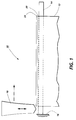
- FIG. 1 is a schematic view in elevation of welding means for welding belts on an anvil.
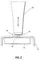
- FIG. 2 is a schematic end view in elevation of welding means for welding belts on an anvil.
- FIG. 3 is a schematic view in elevation of a welding means for welding belts on an anvil.
- FIG. 4 is a schematic clan view of a welding means for welding belts on an anvil.
- FIG 5 is a schematic view in elevation, partly in section, of a welding means for welding means for welding belts on an anvil.
- FIG. 6A is a schematic view of a welding horn for welding belts on an anvil.
- FIG. 6B is a schematic view of a welding horn for welding belts on an anvil, viewed at an angle 90° to the view illustrated in FIG. 6A.
- FIG. 7 is a schematic, sectional view in elevation, partly in section, of the welded joint of a prior art flexible photoreceptor.
- FIG. 8 is a schematic, sectional view in elevation, partly in section, of the welded joint of a prior art flexible photoreceptor after it has been repeatedly cycled.
- a welding station 10 for fabricating belts from a web 12 comprises an anvil 14 cantilevered from a support means 16.
- Anvil 14 supports thermoplastic web 12 during welding of the web by ultrasonic welding horn 18.
- the segments of web 12 supported by anvil 14 comprise overlapping opposite edges 20 and 22 of web 12.
- Welding horn 18 reciprocates vertically as indicated by the vertical arrow.
- welding horn 18 moves horizontally in the direction indicated by the horizontal arrow.
- web 12 such as a thin coated or uncoated thermoplastic web
- anvil 14 supports a lap joint 24 formed from overlapping opposite edges 20 and 22 of web 12.
- Lap joint 24 is welded by contacting lap joint 24 with ultrasonic welding horn 18.
- an ultrasonic belt welding station 10 comprising an ultrasonic welding horn 18 and transducer assembly 30, also referred to as a sonotrode, is illustrated.
- a solenoid 32 is mounted on the upper hinge half 70 to extend or retract ultrasonic welding horn 18 and transducer assembly 30 in a vertical direction.
- the web lap joint 24 (shown in FIG. 2) formed by the overlapping segment ends of thermoplastic web 12 is supported by the upper surface of anvil 14 and held in place below the path of ultrasonic horn and transducer assembly 30 by suction from parallel rows of grooves 33, 34, 36 and 38 in the upper surface of anvil 14 (shown in FIG 3), the grooves leading to vacuum plenums (not shown) within the interior of anvil 14.
- the ultrasonic horn and transducer assembly 30 is supported by assembly 65 comprising two collar clamps mounted to a vertical support mounted to the upper hinged half 70 of a substantially horizontally reciprocateable carriage 44.
- One side of of the lower hinged half 42 of carriage 44 is suspended from pillow blocks 46 and 48 which in turn slide on horizontal bar 50.
- the other side of carriage 44 is suspended from a pair of cam followers 52 that roll on the outer surface of horizontal bar 54.
- a rotatable lead screw 56 drives horizontally reciprocateable carriage 44 through ball screw 58 secured to carriage 44.
- Horizontal bars 50 and 54 as well as lead screw 56 are supported at each end by flanges 60 and 62 which are secured to a suitable support frame (not shown).
- Adjustable set screw 68 is positioned to extend upwardly from the lower hinged half 42 of carriage 44 to assist in maintaining a predetermined spacing between the bottom of the ultrasonic horn of horn and transducer assembly 30 and the top of anvil 14 and to ensure application of a uniform pressure on the web lap joint as the bottom of the ultrasonic horn 18 traverses the lap joint 24 (see FIGS. 1 and 2).
- the end of set screw 68 rests against the bottom of upper hinged half 70 of carriage 44.
- the upper hinged half 70 and lower hinged half 42 of carriage 44 are joined by a hinge comprising a thin metal shim 72 fastened to upper hinged half 70 by bolted plate 74 and fastened to lower hinged half 42 by bolted plate 76.
- the hinge allows upper hinged half 70 of carriage 44 and ultrasonic horn of horn and transducer assembly 30 to pivot along the hinge during welding to compensate in a substantially vertical direction for any irregularities encountered along the lap joint 24 (see FIGS. 1 and 2) during welding.
- An air bellows 78 is positioned between upper hinged half 70 and lower hinged half 42 of carriage 44 to adjust the pressure of the bottom of the ultrasonic horn 18 against the web lap joint 24 (see FIGS. 1 and 2), e.g. to function as a counterbalance.
- ultrasonic horn 18 and transducer assembly 30 are in a retracted position because solenoid 32 is activated.
- Lap joint 24 of overlapping opposite edges 20 and 22 of web 12 (see FIGS. 1 and 2) carried on the upper surface of anvil 14 is securely positioned under the horizontal path to be taken by ultrasonic horn 18.
- Vacuum is applied to grooves 33, 34, 36 and 38 in the upper surface of anvil 14 hold the overlapping opposite edges 20 and 22 of web 12 in place during welding.
- the length of grooves 33, 34, 36 and 38 is normally slightly shorter than the width of web 12. Any suitable vacuum aperture, such as grooves or holes, may be utilized.
- Vacuum plenums (not shown) below the grooves 33, 34, 36 and 38 are connected by passages (not shown) to suitable fittings and hoses through control valves (not shown) to a vacuum source. Activation and inactivation of the vacuum plenums can be independently accomplished by any suitable programmable controller to control conventional valves to connect the vacuum plenums by suitable hoses (not shown) to a source of vacuum or to vent the vacuum plenums to the atmosphere.
- a hard metal strip insert 39 can be utilized in the anvil along the welding path of the welding horn 18 anvil. Strip insert 39 may comprising any suitable material such as stainless steel, A4 tool steel , 02 steel, and the like, which can withstand abrasive conditions such as those encountered during belt lap joint welding.
- Solenoid 32 is inactivated to extend the transducer in ultrasonic horn and transducer assembly 30 toward anvil 14 and adjacent to but not in contact with one end of lap joint 24. Because it is difficult to lower the horn 18 precisely on the extreme edge of the lap joint 24 every time for each fresh web, it is preferred that the horn be lowered adjacent to the edge of the lap joint 24 and then be moved slowly onto the lap joint 24. If desired, horn 18 may be held stationary and lap joint 24 (as well as anvil 14) may be moved relative to horn 18 or both horn 18 and lap joint 24 may be moved relative to each other to effect traversal of horn 18 along lap joint 24. Movement of anvil 14 may be effected by any suitable reciprocatable and conventional means.
- the transducer in ultrasonic horn and transducer assembly 30 is activated and electric motor 66 (see Fig. 4) is activated to drive lead screw 56 at a predetermined speed which in turn moves horizontally reciprocateable carriage 44. Movement of horizontally reciprocateable carriage 44 carries ultrasonic horn 18 into compressive engagement with lap joint 24. The reciprocateable carriage 44 and horn 18 are moved at a predetermined traverse rate along the lap joint to form a welded seam. A reduced initial contact speed or traverse rate can minimize the formation of a raised ridge in the welded seam from one belt to another.
- the welding surface of the ultrasonic horn 18 may be of any suitable shape such as the flat or curved cross-sectional shapes illustrated, for example, in US-A 3,459,610 and US-A 4,532,166.
- the high vibration frequency of the ultrasonic horn 18 along the its vertical axis causes the temperature of at least the contiguous overlapping surfaces of thermoplastic web 12 to increase until at least the thermoplastic material in the overlapping opposite edges 20 and 22 flows. Welding of the contiguous overlapping surfaces of thermoplastic web 12 occurs because the thermoplastic material flows as a result of the applied energy of ultrasonic oscillations.
- thermoplastic material that is induced to melt and weld the lap joint 24 may be provided solely by a coating on the web, from both a coating and a web substrate, or solely from the web itself.
- Web 12 may be of any suitable thickness which will allow adequate heating of the contiguous overlapping surfaces of the web edges by the applied ultrasonic energy to cause the thermoplastic material to melt and weld the overlapping edges of web 12 at lap joint 24. It is believed that the rapid impaction of one edge of web 12 with the other edge of web 12 at the contiguous overlapping web surfaces between the anvil 14 and ultrasonic horn 18 causes generation of heat which maximizes melting of the thermoplastic material.
- the horn 18 may comprise any suitable highly thermoconductive material such as aluminum to ensure achievement of higher temperatures at the interface between the overlapping edges of web 12, to minimize thermal distortion of the exposed surfaces of the web 12, and to remove the heat, generated by the horn, from the thermoplastic material before the tip pressure exerted by horn 18 is removed from the welded seam. This helps prevent the material from boiling and producing a ridge at the seam.
- FIGS. 6A and 6B a preferred welding horn 18 is shown comprising an upper end 90 which has a threaded recess 92 for receiving a threaded stud (not shown) extending from the transducer of the ultrasonic horn and transducer assembly 30 (see FIG. 3).
- Horn 18 is generally cone shaped with a tapered side 94 that terminates at welding tip 96.
- Welding tip 96 has a "chisel " shape with inclined flat faces 97 and 98 that join at an apex or point 99. If desired, the faces 97 and 98 may be of different sizes so that the apex 99 is offset from the axis of horn 18.
- the end of the welding horn 18 may be of any suitable shape
- the shallow chisel profile shown in FIGS. 6A and 6B is a preferred shape.
- the apex 99 is preferably flattened (not shown) by any suitable technique, such as by sanding with 600 grit dry sandpaper or crocus cloth, to form a flat surface with a width, for example, of about 0.4 millimeter to about 1 millimeter.
- the shallow chisel shape and flattened end extends the horn mass closer to the lap joint during welding to enhance absorption of heat and to minimize heat buildup.
- other suitable shapes and sizes well known in the welding art may also be utilized.
- FIG. 7 a cross section of a conventional prior art welded belt photoreceptor 100 is schematically illustrated.
- the ends 102 and 104 of a photoreceptor web employed to form belt photoreceptor 100 overlap to form a lap interface 108.
- the photoreceptor web comprises an anticurl layer 110, a flexible substrate layer 112, a charge generating layer 114 and a charge transport layer 116.
- the anticurl layer 110, flexible substrate layer 112 and charge transport layer 116 comprise solid thermoplastic film forming polymers.
- the weld splash 118 on the outer surface of the belt photoreceptor 100 gradually separates from the upper end 102 of the web during cycling to form an open crevasse or crack 126 which is repeatedly struck by the cleaning blade 127 during image cycling to cause the weld splash 118 on the outer surface of the belt photoreceptor 100 to also separate from the region 122 of the underlying web so that it is held to the belt at a small linear region 125 located along the length of the splash on the side of weld splash 118 opposite the upper end 102 of the photoreceptor web 100.
- This small linear region 125 located along the length of the splash 118 on the side of the splash opposite the upper end 102 of the photoreceptor web 100 functions as a hinge that allows the weld splash 118 to pivot or flop away from the upper end 102 of the photoreceptor web 100 and from the underlying web so that carrier beads and toner particles collected in the space between the web and splash are periodically ejected when the splash flops open and closed as the seam passes the cleaning blade 127 and when it travels around small diameter rollers.
- the ejected material is carried to various subassemblies (e.g. corotrons, lamps) and causes them to fail and ultimately cause copy defects.
- the horn vibration frequencies should be between about 30 kHz and about 45 kHz during the entire contact welding pass over the lap joint to ensure that the thermoplastic material is sufficiently softened and to prevent the formation of splaches that partially separate from the web and flop back and forth during cycle.
- the horn vibration frequencies should be constant at a frequency between about 38 kHz and about 42 kHz during the entire contact welding pass over the lap joint.
- a typical horn suitable for joining thin thermoplastic webs utilizes a sonic generator of about 400-800 watt capacity, an operational frequency of about 40 kHz, and a flat input horn welding surface about 12 millimeters long and about 0.4 to about 1 millimeter wide at the bottom of a generally chisel shaped profile.
- a typical reciprocal motion amplitude for this horn is between about 60 micrometers and about 75 micrometers.
- the combined weight of between about 4.5 kilograms and about 5 kilograms for the solenoid 32, ultrasonic horn and transducer assembly 30, and upper hinged half 70 of carriage 44 is sufficient to bring the horn 18 into forced contact with the lap joint 24.
- thermoplastic photoreceptor web material having a thickness of between about 100 micrometers and about 150 micrometers.
- thicker web materials would require additional dwell time to ensure satisfactory welds.
- thinner web materials would require less dwell time to ensure satisfactory welds.
- the predetermined horn traverse speed is between about 30 millimeters per second and about 70 millimeters per second.
- the welding horn is transported at a rate of between about 45 millimeters per second and about 60 millimeters per second.
- Optimum results are achieved with a welding speed of between about 50 millimeters per second and about 55 millimeters per second.
- the traverse speed is less than about 30 mm/sec the dwell time is too long and the thermoplastic material is melted and then pushed out from under the horn causing the seam to be too weak and to be too wide.
- the horn traverse speed is held constant during the traverse if the thickness of the lap joint is uniform. However, the speed at any point during the weld cycle may be increased or decreased to control the amount of energy being applied or to change the characteristics of the weld itself. For example, the speed can be changed within the limits described herein to accommodate variations in the thickness of the lap joint material along the length of the lap joint.
- the use of a lower initial traverse rate will reduce the likelihood of the horn catching the upper layer of the lap joint upon initial horn contact thereby minimizing ridge formation on the welded belt seam.
- Transport of the horn over the lap joint may be effected by any suitable means.
- a typical transport means is shown in the FIGS. 3, 4 and 5.
- a worm gear drive system other suitable and well known means may be utilized such as a belt and pulley system, a linear motor, a servo controlled motor, and the like.
- the welding means may be stationary and the lap joint may be moved or, alternatively, both the welding means and lap joint may simultaneously be moved relative to the other to achieve traversal of the horn along the lap joint.
- the speed of horn traverse over the lap joint may be changed by any suitable means.
- Typical speed control means include variable speed drives controlled with potentiometers, steppermotors controlled by a closed loop or open loop system, servo-motors controlled by a closed or open loop system, and the like.
- the speed of the variable speed motors can also be controlled by any conventional and suitable programmable controller. Electrical power to drive electrical equipment such as the motors are supplied through suitable wiring and conventional suitable electrical switching.
- the switches and potentiometers can be actuated through suitable circuitry in response to a signal from the programmable controller.
- the control functions in the process of this invention can be synchronized and integrated with a suitable programmable controller such as a Allen Bradley Programmable Controller, Model No. 2/05 or Model No. 2/17.
- the programmable controller responds to various typical inputs including, for example, inputs from limit switches, timers, encoders, proximity sensors, counters and the like and utilizes these inputs for sequencing program outputs to activate electric switches, and the like. Termination of an activated component may be effected by any suitable and conventional means such as by the programmable controller or by suitable limit switches.
- any suitable highly thermally conductive welding horn material may be utilized.
- the horn comprises aluminum because of its superior thermal conductivity and heatsink capabilities. Optimum results are achieved with an aluminum alloy. Particularly preferred is 7075T6 aluminum alloy because of its heat conductivity, hardness and resistance to wear. 7075T6 aluminum alloy is a standard alloy developed for aircraft components.
- Other highly thermally conductive welding horn materials include, for example, titanium.
- the horn preferably should comprise material having a thermal conductivity which facilitate absorption of heat and minimizes heat buildup. The size and mass of the horn should be sufficient to avoid feedback and overload of the power supply employed.
- the end of the welding horn may be of any suitable shape.
- a preferred shape is a shallow chisel profile in which two flat surfaces meet at an apex, the angle between the plane of each surface forming an acute angle of between about 10 degrees and about 30 degrees with an imaginary plane perpendicular to the vertical axis of the horn and intersecting the axis at the point where the apex also intersects the axis.
- This inclined surface functions as a ramp on which the horn rides up onto the lap joint.
- the apex is preferably flattened by a suitable technique, such as by sanding with 600 grit dry sandpaper or crocus cloth, to form a flat surface with a width, for example, of about 0.4 millimeter to about 1 millimeter.
- the shallow chisel shape and flattened end extends the horn mass closer to the lap joint during welding to enhance absorption of heat and to minimize heat buildup.
- the end of the welding horn or the welding surface may be in the form of a flat surface having the shape of a round dot having a diameter of about 4 millimeters.
- the apex length is greater than the length of seam overlap and width of the splash to compensate for any for error in placing the seam under the horn.
- a typical apex length is about 30 percent greater than the length of seam overlap.
- the anvil underlying the overlapped seam during welding is a rigid surface which can withstand the rigors of the welding process.
- Typical anvil surfaces include metals such as stainless steel, A4 tool steel, O2 steel, and the like.
- the anvil moves during welding to provide relative motion between a moving or stationary welding horn, such movement may be accomplished by any suitable means such as a lead screw and ball arrangement, belt and pulley drive, and the like.
- the distance from the bottom of the horn at the midpoint of each vertical stroke relative to the surface of the anvil during welding of the lap joint is dependent upon the thickness of the thermoplastic material.
- the bottom of the horn at the midpoint of each vertical stroke relative to the surface of the anvil during welding of the lap joint should be at a distance between about 10 and about 75 percent of the thickness of the lap joint being welded.
- the distance is between about 35 percent and about 70 percent of the thickness of the lap joint being welded.
- Optimum welded seam integrity and smoothness is achieved with a distance of between about 45 percent and about 55 percent of the thickness of the lap joint being welded.
- each horn stroke may be of any suitable length. Typical stroke lengths range from about 50 micrometers to about 150 micrometers. Preferably, the stroke length selected should not be so long that the horn strikes the anvil surface. even if the horn initially contacts the anvil prior to riding up on the lap joint, once the horn tip is on the lap joint, the lap joint will support the weight of the welding fixture and increase the distance between the horn tip and the anvil.
- Any suitable seam overlap may be utilized.
- a preferred range of overlap is between about 0.7 millimeter and about 1.7 millimeters.
- thermoplastic layer Any suitable thin, flexible web comprising a thermoplastic layer may be usedfor the web 12.
- the web may comprise a single layer or a plurality of layers in which at least one of the layers comprises thermoplastic material.
- Any suitable thermoplastic, polymeric material which will melt at the temperatures generated at the contiguous overlapping web surfaces of the seam may be utilized.
- Typical thermoplastic, polymeric materials include polyethylenes, polypropylenes, polycarbonates, polyvinylacetate, terephthalic acid resins, polyvinylchloride, styrene-butadiene copolymers and the like.
- thermoplastic material that is induced to melt and weld the seam may be provided solely by a thermoplastic coating on the web, from both a coating and a web substrate, or solely from the web itself.
- a nonthermoplastic web substrate may be coated with a thermoplastic material which is the sole source of the material which melts.
- the web may be uncoated and consist entirely of the thermoplastic material, some of which melts to weld the seam.
- the web may be of any suitable thickness which will allow adequate heating of the contiguous overlapping surfaces of the web edges to permit sufficient heat energy to be applied at the contiguous overlapping surfaces to cause the thermoplastic material to melt and weld the overlapping edges of web at the seam.
- Preferred web thicknesses for use with ultrasonic welding can range from between about 25 micrometers to about 500 micrometers. Thicker webs may be utilized as long as sufficient heat is applied to the contiguous overlapping surfaces of the web to cause the thermoplastic material to melt. Webs having a thickness up to about 10 millimeters may be joined with the process and apparatus described above with reference to the drawings.
- a preferred flexible web comprises an anticurl layer, a substrate layer, an optional charge blocking layer, an optional adhesive layer, a charge generating layer and a charge transport layer.
- These flexible multilayered electrophotographic imaging members are well known in the art and described, for example, in US-A 4,654,284 and US-A 4,786,570.
- the web containing the aperture may be thermoplastic or non-thermoplastic.
- the described technique may be utilized to join dissimilar or similar materials.
- the fabrication of a flexible belt is a preferred application, the process may be utilized to join multiple sheets or webs.
- sheet is intended to encompass webs, sheets, straps, and the like.
- the webs may be of any suitable shape and may be separate “webs or a single web. The opposite edges of a single web may be joined to form, for example, a continuous loop, belt or mobius strip.
- a web of polyester film (Mylar, available from E. l. duPont de Nemours and Co.) having a width of about 33.5 cm, a length of about 59 cm and a thickness of about 76 micrometers and having a first coating on one side of a polyester having a thickness of about 0.2 micrometer and a second coating comprising polyvinyl carbazole about 3 micrometers thick was coated on both sides with a layer comprising polycarbonate resin, each polycarbonate coating having a thickness of about 25 micrometers.
- This web was processed in an apparatus similar to the apparatus illustrated in the drawings.
- the leading edge of the web was placed on along the length of the upper surface of an anvil having a width of about 10 cm and a length of about 50 cm and held in place by a vacuum applied to apertures in the anvil underlying the leading edge of the web.
- the web covered slightly more than half of the upper surface of the anvil.
- the opposite edge of the web was brought under the anvil and placed on the exposed portion of the upper surface of the mandrel and over part of the leading edge of the web that was previously placed on the mandrel. The opposite edge overlapped the leading edge by about 1.2 mm.
- the opposite edge was held in place by a vacuum applied to apertures in the anvil underlying the opposite edge of the web.
- the anvil carrying the newly formed belt loop was then positioned under a reciprocateable ultrasonic welding horn.
- the ultrasonic welding horn supported in a carriage was lowered against the web lap joint.
- the horn was biased against the seam due to the controlled weight of about 4.5 kilograms of horn, transducer, bracket and any counterweight pressing against the seam supported by the mandrel.
- the horn was formed from 7075 T6 aluminum and had a generally chisel shaped input horn welding surface in which the point of the chisel was about 12 millimeters long with a flattened chisel "point" about 0.4 to 1 mm wide.
- the horn was operated at a frequency of 20 kHz and a motion amplitude of about 76 micrometers and was driven by a Branson 20 Khz 800 watt power supply with amplitude adjustment module, a Branson 00 Khz 2.0:1 booster aluminum 101-149-081 and a Branson 20 Khz converter.
- the horn was transported by the carriage in a substantially horizontal path along the web lap joint at a constant rate of about 50 millimeters per second.
- the carriage was driven by a worm gear which was in turn rotated by a belt connected to the shaft of an electric motor. During welding, the horn was allowed to freely move vertically to accommodate variations in the web lap joint thickness.
- the welding surface of the horn reciprocated through a distance of about 70 micrometers and the total distance between the welding surface of the reciprocating horn (from the midpoint of the stroke) and the surface of the underlying anvil was about 102 micrometers.
- This welding procedure caused the thermoplastic materials in the web to uniformly melt and weld the web seam.
- the ultrasonic welding horn was raised away from the web lap joint to a retracted position.
- the seam (lap joint) after welding had a thickness of about 220 micrometers.
- a splash i.e.
- a web of polyester film (Mylar, available from E. l. duPont de Nemours and Co.) having a width of about 33.5 cm, a length of about 59 cm and a thickness of about 76 micrometers and having a first coating on one side of a polyester having a thickness of about 0.2 micrometer and a second coating comprising polyvinyl carbazole about 3 micrometers thick was coated on both sides with a layer comprising polycarbonate resin, each polycarbonate coating having a thickness of about 25 micrometers.
- This web was processed in an apparatus similar to the apparatus illustrated in the drawings.
- the leading edge of the web was placed on along the length of the upper surface of an anvil having a width of about 10 cm and a length of about 50 cm and held in place by a vacuum applied to apertures in the anvil underlying the leading edge of the web.
- the web covered slightly more than half of the upper surface of the anvil.
- the opposite edge of the web was brought under the anvil and placed on the exposed portion of the upper surface of the mandrel and over part of the leading edge of the web that was previously placed on the mandrel. The opposite edge overlapped the leading edge by about 0.9 mm.
- the opposite edge was held in place by a vacuum applied to apertures in the anvil underlying the opposite edge of the web.
- the anvil carrying the newly formed belt loop was then positioned under a reciprocateable ultrasonic welding horn.
- the ultrasonic welding horn supported in a carriage was lowered against the web lap joint.
- the horn was biased against the seam due to the controlled weight of about 4.5 to 5 kilograms of horn, transducer, bracket and any counterweight pressing against the seam supported by the mandrel.
- the horn was formed from 7075T6 aluminum alloy.
- the horn had a generally chisel shaped input horn welding surface in which the point of the chisel (similar to that illustrated in FIGS.
- 6A and 6B was about 12 millimeters long, but flattened by lapping with 600 grit dry sandpaper to form a flat rectangular surface at the "point" having a width of about 0.5 mm and a length of about 12 millimeters.
- the horn was operated at a frequency of 40 kHz and a motion amplitude of about 60 - 75 micrometers and was driven by a Branson 40 kHz 4MB3 800 watt power supply with amplitude adjustment module VU-1, a Branson 40 Khz 2.0:1 booster aluminum 101-149-081, and a Branson 40 Khz converter 101-135-042.
- the horn was transported by the carriage in a substantially horizontal path along the web lap joint at a constant rate of about 37 millimeters per second.
- the carriage was driven by a worm gear which was in turn rotated by a belt connected to the shaft of an electric motor.
- the horn was allowed to freely move vertically to accommodate variations in the web lap joint thickness.
- the welding surface of the horn reciprocated through a distance of about 30 - 40 micrometers and the total distance between the welding surface of the reciprocating horn (from the midpoint of the stroke) and the surface of the underlying anvil was about 102 micrometers. This welding procedure caused the thermoplastic materials in the web to uniformly melt and weld the web seam.
- the ultrasonic welding horn was raised away from the web lap joint to a retracted position.
- the seam (lap joint) after welding had a thickness of about 220 micrometers.
- a splash i.e. deposit of web material melted during welding
- the splash had a cross section similar to that illustrated in FIG 7.
- Belts prepared by this welding technique were rapidly cycled to make copies in a test device containing a 3 roll belt support structure having at least one roll having a diameter of 19 mm and doctor blade cleaning system identical to the test fixture described in Example l.
- the belts were periodically examined during cycling for any cracks formed by separation of the outer splash material from the web substrate.
- a belt was considered unacceptable when one or more separations of the outer splash material from the web substrate exceeded a total distance of 35 mm as measured along the length of the welded seam. It was found that the average number of hours of cycling to the point of unacceptability was about 220 hours. Thus the life of the belts prepared by the process of this invention was almost three times as long as that of the prior art control process described in Example I.
Landscapes
- Engineering & Computer Science (AREA)
- Mechanical Engineering (AREA)
- Lining Or Joining Of Plastics Or The Like (AREA)
Abstract
A process is described for welding sheet material (12) comprising a thermoplastic polymer. The process comprises overlapping edges (20, 22) of the sheet material to form a lap joint, supporting the lap joint on an anvil (14), and welding the lap joint by contacting and traversing the lap joint with an ultrasonic welding horn (18). The welding horn is oscillated at a frequency of between about 30 kHz and about 45 kHz while contacting and traversing the lap joint with the welding horn. The welding horn is preferably highly thermally conductive.
Description
- This invention relates in general to a process for welding flexible webs and more specifically to a process for welding webs using high frequency welding techniques.
- Various techniques have been devised to form belts from webs. Thermoplastic webs may be joined by overlapping the edge of one web over another and placing the overlapped or seam portion of the webs over a base beneath a vibrating welding element. The vibrating welding element may be a horn vibrating at an ultrasonic frequency while it is brought into forced contact with one side of the overlapped webs while the other side of the overlapped web seam is supported on an anvil surface. Transfer of vibratory energy from the horn to the web material is effected upon impact of a suitably shaped surface of the horn on the seam of the web material. The vibrating energy causes surface heat to be generated between the overlapping webs along the area of contiguous contact between the webs. The horn normally resonates toward and away from the seam at a frequency of about 16 kHz or higher, e.g. 20 kHz. A typical welding horn amplitude at a frequency of about 20 kHz is about 80 micrometers and a typical welding horn traverse rate is between about 4 centimeters per second and about 7 centimeters per second. Thus, for example, a traverse speed of about 5 centimeters per second is described in US-A 4,838,964. The weld may be in the form of a chain of spots along the seam or a continuous weld. The technique of ultrasonic welding of thermoplastic material is well known and illustrated, for example, in US-A 4,532,166, US-A 4,838,964, US-A 3,879,256, US-A 3,939,033, US-A 3,947,307 and US-A 3,459,610, all of these patents being incorporated by reference herein in their entirety.
- Acceptable welds for forming belt shaped electrophotographic imaging members have been obtained which perform satisfactorily when transported around relatively large diameter rollers. The welded seams of these belts contain a deposit of web material melted during welding. These deposits or "weld splashes" are formed on each side of the welded web adjacent to and adhering to each end of the original web and to the regions of the web underlying each splash. Unfortunately, when the belts are transported around very small diameter rollers having, for example a diameter of about 19 mm, the weld splash on the outer surface of the belt gradually separates from the upper end of the photoreceptor web during cycling to form an open crevasse or crack which is repeatedly struck by the cleaning blade during image cycling to cause the weld splash on the outer surface of the belt to also separate from the underlying web so that it is held to the belt at a small linear region located along the length of the splash on the side of the splash opposite the upper end of the photoreceptor web this small linear region located along the length of the splash on the side of the splash opposite the upper end of the photoreceptor web functions as a hinge that allows the weld splash to pivot or flop away from the upper end of the photoreceptor web and from the underlying web so that carrier beads and toner particles collected in the space between the web and splash are periodically ejected when the splash flops open and closed when the seam passes the cleaning blade and also when it travels around small diameter rollers. The ejected material is carried to various subassemblies (e.g. corotrons, lamps) and causes them to fail and ultimately cause copy defects. Collisions of the blade with the flopping splash results in the blade becoming chipped and pitted. These chips and pits in the blade leave streaks of toner on the photoreceptor surface which eventually appear as streaks on copies made during subsequent electrophotographic imaging cycles and adversely affect image quality.
- The following prior art has been noted:
US-A Reissue 33,063 reissued to Obeda on September 19, 1989 - Apparatus and method are disclosed for welding two sheets of thermoplastic materials. A tapered horn having a serrated or knurled tip is vibrated at typically 40 KHz along the longitudinal axis of the horn in a direction transverse to the axis of a nip between a pair of rollers. The linear rate of sheet movement past each side of the horn tip should be between 3 to 4 feet per minute but depends on the thickness of the sheets. The speed should be relative to the amount of heat produced by the tip to provide a proper weld. The born melts the facing surfaces of the two sheet and the rollers press and weld the sheets together.
US-A 4,532,166 issued to Thomsen et al on July 30, 1985 - A welded web is disclosed in which a first edge overlaps a second edge of a web, the first edge having at least one aperture which is at least partially filled with thermoplastic material from the second edge. Ultrasonic welding frequencies of 16 kHz or higher, e.g. 20 kHz, are disclosed. The welding horn is disclosed as traversing the seam at about 5 cm per second.
US-A 4,838,964 issued to Thomsen et al. on June 13, 1989 - A process is disclosed for fabricating belts by overlapping the edges of the belt to form a loop, transferring the loop to an anvil of a welding station and welding the belt. Ultrasonic welding frequencies of 16 kHz or higher, e.g. 20 kHz, are disclosed. The welding horn is disclosed as traversing the seam at about 5 cm per second.
US-A 3,717,539 issued to Roberts on February 20, 1973 - Ultrasonic welding apparatus and method are disclosed for welding moving sheets of plastic. The rate of travel of the plastic sheets is typically one-half inch per second and ultrasonic vibration is set at 20,000 cycles per second. A cooling means is included for quenching the workpieces while being compressed to improve the weld. See, for example, Fig 2.
US-A 4,496,095 issued to Renshaw et al. on January 29, 1985 - A method of progressively ultrasonically welding together metallic workpieces is disclosed utilizing an ultrasonic welding apparatus having a welding tip and complimentary anvil between which pieces are inserted. The workpieces are clamped, presqueezed and initial pressure and energy are introduced to scrub the workpieces. Then pressure and energy are synchronously ramped in phase to maximum levels to effect a spot weld on the workpiece while it is stationary. The spot weld is controlled automatically. See, for example, Fig. 1 showing the apparatus and Fig. 2 showing a graph of the power and timing cycle.
US-A 3,678,566 issued to Ellis et al. on July 25, 1972 - A friction welding process is disclosed in which the rate of axial shortening of a metallic workpiece due to burn-off during rotation is measured and this rate is used as a guide to determine the quality of a weld. Deviations are used to adjust the axial pressure to reduce the deviation, or as an alternative, the speed and relative rotation may be adjusted.
US-A 3,610,506 issued to Robinson on October 5, 1971 - A method is disclosed for ultrasonic welding of metals using a variable welding force. Force is applied to a stationary work by stationary welding apparatus at the start of a welding period, but the force applied rises more slowly than normal. See, for example, Figs 1 and 2. - When ultrasonic welding techniques are utilized to to fabricate belts having welded seams, particularly photoreceptors in electrostatographic copiers, duplicators, printers and the like that are transported over small diameter rollers, copy quality can deteriorate when blade cleaning is used during image cycling. Thus, the characteristics of belt welding systems exhibit deficiencies in the manufacture of belts that must meet extended life requirements.
- It is an object of this invention to provide a welding process which enables above-noted disadvantages to be overcome.
- The present invention provides a process for welding comprising providing sheet material comprising a thermoplastic polymer, overlapping edges of the sheet material to form a lap joint, supporting the lap joint on an anvil, welding the lap joint by contacting and traversing the lap joint with an ultrasonic welding horn, and oscillating the welding horn at a frequency of between about 30 kHz and about 45 kHz while contacting and traversing the lap joint with the welding horn. The welding horn is preferably highly thermally conductive.
- By way of example only embodiments of the invention will be described with reference to the accompanying drawings wherein:
- FIG. 1 is a schematic view in elevation of welding means for welding belts on an anvil.
- FIG. 2 is a schematic end view in elevation of welding means for welding belts on an anvil.
- FIG. 3 is a schematic view in elevation of a welding means for welding belts on an anvil.
- FIG. 4 is a schematic clan view of a welding means for welding belts on an anvil.
- FIG 5 is a schematic view in elevation, partly in section, of a welding means for welding means for welding belts on an anvil.
- FIG. 6A is a schematic view of a welding horn for welding belts on an anvil.
- FIG. 6B is a schematic view of a welding horn for welding belts on an anvil, viewed at an
angle 90° to the view illustrated in FIG. 6A. - FIG. 7 is a schematic, sectional view in elevation, partly in section, of the welded joint of a prior art flexible photoreceptor.
- FIG. 8 is a schematic, sectional view in elevation, partly in section, of the welded joint of a prior art flexible photoreceptor after it has been repeatedly cycled.
- Referring to FIG. 1, a
welding station 10 for fabricating belts from aweb 12 is shown.Welding station 10 comprises ananvil 14 cantilevered from a support means 16. Anvil 14 supportsthermoplastic web 12 during welding of the web byultrasonic welding horn 18. The segments ofweb 12 supported byanvil 14 comprise overlappingopposite edges web 12. Thus, the direction of reciprocation ofhorn 18 is perpendicular to the plane of the segments ofweb 12 supported byanvil 14. Weldinghorn 18 reciprocates vertically as indicated by the vertical arrow. During welding of the overlapping opposite edges 20 and 22 ofweb 12 by weldinghorn 18, weldinghorn 18 moves horizontally in the direction indicated by the horizontal arrow. - As shown in FIG. 2,
web 12, such as a thin coated or uncoated thermoplastic web, is supported byanvil 14. More specifically,anvil 14 supports a lap joint 24 formed from overlapping opposite edges 20 and 22 ofweb 12. Lap joint 24 is welded by contacting lap joint 24 withultrasonic welding horn 18. - Referring to Figs. 3, 4, 5 and 6, an ultrasonic
belt welding station 10 comprising anultrasonic welding horn 18 andtransducer assembly 30, also referred to as a sonotrode, is illustrated. Asolenoid 32 is mounted on theupper hinge half 70 to extend or retractultrasonic welding horn 18 andtransducer assembly 30 in a vertical direction. The web lap joint 24 (shown in FIG. 2) formed by the overlapping segment ends ofthermoplastic web 12 is supported by the upper surface ofanvil 14 and held in place below the path of ultrasonic horn andtransducer assembly 30 by suction from parallel rows ofgrooves anvil 14. The ultrasonic horn andtransducer assembly 30 is supported byassembly 65 comprising two collar clamps mounted to a vertical support mounted to the upper hingedhalf 70 of a substantially horizontallyreciprocateable carriage 44. One side of of the lower hingedhalf 42 ofcarriage 44 is suspended from pillow blocks 46 and 48 which in turn slide onhorizontal bar 50. The other side ofcarriage 44 is suspended from a pair ofcam followers 52 that roll on the outer surface ofhorizontal bar 54. Arotatable lead screw 56 drives horizontallyreciprocateable carriage 44 throughball screw 58 secured tocarriage 44.Horizontal bars lead screw 56 are supported at each end byflanges screw 56 is rotated by abelt 64 driven byelectric motor 66 which is also supported by a suitable support frame (not shown).Adjustable set screw 68 is positioned to extend upwardly from the lower hingedhalf 42 ofcarriage 44 to assist in maintaining a predetermined spacing between the bottom of the ultrasonic horn of horn andtransducer assembly 30 and the top ofanvil 14 and to ensure application of a uniform pressure on the web lap joint as the bottom of theultrasonic horn 18 traverses the lap joint 24 (see FIGS. 1 and 2). The end ofset screw 68 rests against the bottom of upper hingedhalf 70 ofcarriage 44. The upper hingedhalf 70 and lower hingedhalf 42 ofcarriage 44 are joined by a hinge comprising athin metal shim 72 fastened to upper hingedhalf 70 by bolted plate 74 and fastened to lower hingedhalf 42 by boltedplate 76. The hinge allows upper hingedhalf 70 ofcarriage 44 and ultrasonic horn of horn andtransducer assembly 30 to pivot along the hinge during welding to compensate in a substantially vertical direction for any irregularities encountered along the lap joint 24 (see FIGS. 1 and 2) during welding. An air bellows 78 is positioned between upper hingedhalf 70 and lower hingedhalf 42 ofcarriage 44 to adjust the pressure of the bottom of theultrasonic horn 18 against the web lap joint 24 (see FIGS. 1 and 2), e.g. to function as a counterbalance. - In operation,
ultrasonic horn 18 andtransducer assembly 30 are in a retracted position becausesolenoid 32 is activated. Lap joint 24 of overlappingopposite edges anvil 14 is securely positioned under the horizontal path to be taken byultrasonic horn 18. Vacuum is applied togrooves anvil 14 hold the overlapping oppositeedges web 12 in place during welding. The length ofgrooves web 12. Any suitable vacuum aperture, such as grooves or holes, may be utilized. Vacuum plenums (not shown) below thegrooves metal strip insert 39 can be utilized in the anvil along the welding path of thewelding horn 18 anvil. Strip insert 39 may comprising any suitable material such as stainless steel, A4 tool steel , 02 steel, and the like, which can withstand abrasive conditions such as those encountered during belt lap joint welding. -
Solenoid 32 is inactivated to extend the transducer in ultrasonic horn andtransducer assembly 30 towardanvil 14 and adjacent to but not in contact with one end of lap joint 24. Because it is difficult to lower thehorn 18 precisely on the extreme edge of the lap joint 24 every time for each fresh web, it is preferred that the horn be lowered adjacent to the edge of the lap joint 24 and then be moved slowly onto the lap joint 24. If desired,horn 18 may be held stationary and lap joint 24 (as well as anvil 14) may be moved relative to horn 18 or bothhorn 18 and lap joint 24 may be moved relative to each other to effect traversal ofhorn 18 along lap joint 24. Movement ofanvil 14 may be effected by any suitable reciprocatable and conventional means. The transducer in ultrasonic horn andtransducer assembly 30 is activated and electric motor 66 (see Fig. 4) is activated to drivelead screw 56 at a predetermined speed which in turn moves horizontallyreciprocateable carriage 44. Movement of horizontallyreciprocateable carriage 44 carriesultrasonic horn 18 into compressive engagement with lap joint 24. Thereciprocateable carriage 44 andhorn 18 are moved at a predetermined traverse rate along the lap joint to form a welded seam. A reduced initial contact speed or traverse rate can minimize the formation of a raised ridge in the welded seam from one belt to another. - The welding surface of the
ultrasonic horn 18 may be of any suitable shape such as the flat or curved cross-sectional shapes illustrated, for example, in US-A 3,459,610 and US-A 4,532,166. The high vibration frequency of theultrasonic horn 18 along the its vertical axis causes the temperature of at least the contiguous overlapping surfaces ofthermoplastic web 12 to increase until at least the thermoplastic material in the overlapping oppositeedges thermoplastic web 12 occurs because the thermoplastic material flows as a result of the applied energy of ultrasonic oscillations. The thermoplastic material that is induced to melt and weld the lap joint 24 may be provided solely by a coating on the web, from both a coating and a web substrate, or solely from the web itself.Web 12 may be of any suitable thickness which will allow adequate heating of the contiguous overlapping surfaces of the web edges by the applied ultrasonic energy to cause the thermoplastic material to melt and weld the overlapping edges ofweb 12 at lap joint 24. It is believed that the rapid impaction of one edge ofweb 12 with the other edge ofweb 12 at the contiguous overlapping web surfaces between theanvil 14 andultrasonic horn 18 causes generation of heat which maximizes melting of the thermoplastic material. If desired, thehorn 18 may comprise any suitable highly thermoconductive material such as aluminum to ensure achievement of higher temperatures at the interface between the overlapping edges ofweb 12, to minimize thermal distortion of the exposed surfaces of theweb 12, and to remove the heat, generated by the horn, from the thermoplastic material before the tip pressure exerted byhorn 18 is removed from the welded seam. This helps prevent the material from boiling and producing a ridge at the seam. - In FIGS. 6A and 6B a
preferred welding horn 18 is shown comprising anupper end 90 which has a threadedrecess 92 for receiving a threaded stud (not shown) extending from the transducer of the ultrasonic horn and transducer assembly 30 (see FIG. 3).Horn 18 is generally cone shaped with atapered side 94 that terminates at weldingtip 96. Weldingtip 96 has a "chisel " shape with inclined flat faces 97 and 98 that join at an apex orpoint 99. If desired, thefaces horn 18. Although the end of thewelding horn 18 may be of any suitable shape, the shallow chisel profile shown in FIGS. 6A and 6B is a preferred shape. The apex 99 is preferably flattened (not shown) by any suitable technique, such as by sanding with 600 grit dry sandpaper or crocus cloth, to form a flat surface with a width, for example, of about 0.4 millimeter to about 1 millimeter. The shallow chisel shape and flattened end extends the horn mass closer to the lap joint during welding to enhance absorption of heat and to minimize heat buildup. However, other suitable shapes and sizes well known in the welding art may also be utilized. - Referring to FIG. 7 a cross section of a conventional prior art welded
belt photoreceptor 100 is schematically illustrated. The ends 102 and 104 of a photoreceptor web employed to formbelt photoreceptor 100 overlap to form alap interface 108. The photoreceptor web comprises ananticurl layer 110, aflexible substrate layer 112, acharge generating layer 114 and acharge transport layer 116. Generally, theanticurl layer 110,flexible substrate layer 112 andcharge transport layer 116 comprise solid thermoplastic film forming polymers. After completion of welding of prior art belt photoreceptors at a frequency of about 20 kHz, a deposit of web material melted during welding forms weld splashes 118 and 120 on each side of web 106 adjacent to and adhering to eachend regions splash - As shown in FIG. 8, upon extended cycling of
belt photoreceptor 100 around very small diameter rollers to form electrophotographic images oncharge transport layer 116, theweld splash 118 on the outer surface of thebelt photoreceptor 100 gradually separates from theupper end 102 of the web during cycling to form an open crevasse or crack 126 which is repeatedly struck by thecleaning blade 127 during image cycling to cause theweld splash 118 on the outer surface of thebelt photoreceptor 100 to also separate from theregion 122 of the underlying web so that it is held to the belt at a smalllinear region 125 located along the length of the splash on the side ofweld splash 118 opposite theupper end 102 of thephotoreceptor web 100. This smalllinear region 125 located along the length of thesplash 118 on the side of the splash opposite theupper end 102 of thephotoreceptor web 100 functions as a hinge that allows theweld splash 118 to pivot or flop away from theupper end 102 of thephotoreceptor web 100 and from the underlying web so that carrier beads and toner particles collected in the space between the web and splash are periodically ejected when the splash flops open and closed as the seam passes thecleaning blade 127 and when it travels around small diameter rollers. The ejected material is carried to various subassemblies (e.g. corotrons, lamps) and causes them to fail and ultimately cause copy defects. Collisions of theblade 127 with theflopping splash 118 results in theblade 127 becoming chipped and pitted. These chips and pits in the blade leave streaks of toner on the photoreceptor web surface which eventually appear as streaks on copies made during subsequent electrophotographic imaging cycles and adversely affect image quality. - For satisfactory results, the horn vibration frequencies should be between about 30 kHz and about 45 kHz during the entire contact welding pass over the lap joint to ensure that the thermoplastic material is sufficiently softened and to prevent the formation of splaches that partially separate from the web and flop back and forth during cycle. Preferably, for stronger welds and greater adhesion of the weld splash to the web, the horn vibration frequencies should be constant at a frequency between about 38 kHz and about 42 kHz during the entire contact welding pass over the lap joint. A typical horn suitable for joining thin thermoplastic webs utilizes a sonic generator of about 400-800 watt capacity, an operational frequency of about 40 kHz, and a flat input horn welding surface about 12 millimeters long and about 0.4 to about 1 millimeter wide at the bottom of a generally chisel shaped profile. A typical reciprocal motion amplitude for this horn is between about 60 micrometers and about 75 micrometers. The combined weight of between about 4.5 kilograms and about 5 kilograms for the
solenoid 32, ultrasonic horn andtransducer assembly 30, and upper hingedhalf 70 ofcarriage 44 is sufficient to bring thehorn 18 into forced contact with the lap joint 24. However, air bellows, a spring bias, weights, counterweights, or other suitable means may be utilized to increase or decrease the contact force. Since heat is generated very rapidly at the interface of the overlapping web ends at the lap joint with this type of device, sufficient heat to cause the thermoplastic materials to melt can occur typically in about 0.01 second and about 0.25 second as the horn traverses the along lap joint 24. For example, at a relatively high traverse rate of about 70 mm/sec, and a horn tip width of 0.7 mm, the horn tip is typically in contact with a particular point of the lap joint for about .01 second. These conditions are typical for thermoplastic photoreceptor web material having a thickness of between about 100 micrometers and about 150 micrometers. However, thicker web materials would require additional dwell time to ensure satisfactory welds. Similarly, thinner web materials would require less dwell time to ensure satisfactory welds. - As the
horn 18 is lowered to the lap joint ofweb 24, electrical power is supplied to the transducer in the ultrasonic horn andtransducer assembly 30 andelectric motor 66 is activated to initially drivelead screw 56 at the predetermined first speed or rate which in turn moves horizontallyreciprocateable carriage 44 andultrasonic welding horn 18 along the lap joint ofweb 24. Aftercarriage 44 completes its traversal of the lap joint,solenoid 32 is activated to retract the transducer in ultrasonic horn andtransducer assembly 30 away fromanvil 14, the transducer in ultrasonic horn andtransducer assembly 30 is inactivated andsolenoid 32 is inactivated andelectric motor 66 is reversed to return horizontallyreciprocateable carriage 44 to its starting position. - Satisfactory welding results may be achieved when the predetermined horn traverse speed is between about 30 millimeters per second and about 70 millimeters per second. Preferably, the welding horn is transported at a rate of between about 45 millimeters per second and about 60 millimeters per second. Optimum results are achieved with a welding speed of between about 50 millimeters per second and about 55 millimeters per second. When the horn traverses the seam at greater than about 70 mm/sec, the thermoplastic layers tend to not join because insufficient energy is transmitted the material and the material does not reach a temperature sufficient to allow the layers to join properly. When the traverse speed is less than about 30 mm/sec the dwell time is too long and the thermoplastic material is melted and then pushed out from under the horn causing the seam to be too weak and to be too wide. The horn traverse speed is held constant during the traverse if the thickness of the lap joint is uniform. However, the speed at any point during the weld cycle may be increased or decreased to control the amount of energy being applied or to change the characteristics of the weld itself. For example, the speed can be changed within the limits described herein to accommodate variations in the thickness of the lap joint material along the length of the lap joint. The use of a lower initial traverse rate will reduce the likelihood of the horn catching the upper layer of the lap joint upon initial horn contact thereby minimizing ridge formation on the welded belt seam.
- Transport of the horn over the lap joint may be effected by any suitable means. A typical transport means is shown in the FIGS. 3, 4 and 5. Instead of a worm gear drive system, other suitable and well known means may be utilized such as a belt and pulley system, a linear motor, a servo controlled motor, and the like. If desired, the welding means may be stationary and the lap joint may be moved or, alternatively, both the welding means and lap joint may simultaneously be moved relative to the other to achieve traversal of the horn along the lap joint. The speed of horn traverse over the lap joint may be changed by any suitable means. Typical speed control means include variable speed drives controlled with potentiometers, steppermotors controlled by a closed loop or open loop system, servo-motors controlled by a closed or open loop system, and the like. The speed of the variable speed motors can also be controlled by any conventional and suitable programmable controller. Electrical power to drive electrical equipment such as the motors are supplied through suitable wiring and conventional suitable electrical switching. The switches and potentiometers can be actuated through suitable circuitry in response to a signal from the programmable controller. Thus, for example, the control functions in the process of this invention can be synchronized and integrated with a suitable programmable controller such as a Allen Bradley Programmable Controller, Model No. 2/05 or Model No. 2/17. The programmable controller responds to various typical inputs including, for example, inputs from limit switches, timers, encoders, proximity sensors, counters and the like and utilizes these inputs for sequencing program outputs to activate electric switches, and the like. Termination of an activated component may be effected by any suitable and conventional means such as by the programmable controller or by suitable limit switches.
- Any suitable highly thermally conductive welding horn material may be utilized. Preferably, the horn comprises aluminum because of its superior thermal conductivity and heatsink capabilities. Optimum results are achieved with an aluminum alloy. Particularly preferred is 7075T6 aluminum alloy because of its heat conductivity, hardness and resistance to wear. 7075T6 aluminum alloy is a standard alloy developed for aircraft components. Other highly thermally conductive welding horn materials include, for example, titanium. Generally, the horn preferably should comprise material having a thermal conductivity which facilitate absorption of heat and minimizes heat buildup. The size and mass of the horn should be sufficient to avoid feedback and overload of the power supply employed. The end of the welding horn may be of any suitable shape. A preferred shape is a shallow chisel profile in which two flat surfaces meet at an apex, the angle between the plane of each surface forming an acute angle of between about 10 degrees and about 30 degrees with an imaginary plane perpendicular to the vertical axis of the horn and intersecting the axis at the point where the apex also intersects the axis. This inclined surface functions as a ramp on which the horn rides up onto the lap joint. The apex is preferably flattened by a suitable technique, such as by sanding with 600 grit dry sandpaper or crocus cloth, to form a flat surface with a width, for example, of about 0.4 millimeter to about 1 millimeter. The shallow chisel shape and flattened end extends the horn mass closer to the lap joint during welding to enhance absorption of heat and to minimize heat buildup. However, other suitable shapes and sizes well known in the welding art may also be utilized. For example, the end of the welding horn or the welding surface may be in the form of a flat surface having the shape of a round dot having a diameter of about 4 millimeters. Preferably, the apex length is greater than the length of seam overlap and width of the splash to compensate for any for error in placing the seam under the horn. A typical apex length is about 30 percent greater than the length of seam overlap.
- Generally, the anvil underlying the overlapped seam during welding is a rigid surface which can withstand the rigors of the welding process. Typical anvil surfaces include metals such as stainless steel, A4 tool steel, O2 steel, and the like. For embodiments where the anvil moves during welding to provide relative motion between a moving or stationary welding horn, such movement may be accomplished by any suitable means such as a lead screw and ball arrangement, belt and pulley drive, and the like.
- The distance from the bottom of the horn at the midpoint of each vertical stroke relative to the surface of the anvil during welding of the lap joint is dependent upon the thickness of the thermoplastic material. Generally, the bottom of the horn at the midpoint of each vertical stroke relative to the surface of the anvil during welding of the lap joint should be at a distance between about 10 and about 75 percent of the thickness of the lap joint being welded. Preferably the distance is between about 35 percent and about 70 percent of the thickness of the lap joint being welded. Optimum welded seam integrity and smoothness is achieved with a distance of between about 45 percent and about 55 percent of the thickness of the lap joint being welded. If the distance between the horn and the anvil is greater than 75 percent of the lap joint being welded there will not be enough pressure on the seam to form the bond between the two layers and a weak weld will be obtained. If the distance is less than 10 percent of the thickness of the lap joint the horn will try to lift the top layer of the overlapped material and not start the weld correctly and it is also more likely that the horn will hit the anvil when it begins its vibratory motion and damage the horn. The length of each horn stroke may be of any suitable length. Typical stroke lengths range from about 50 micrometers to about 150 micrometers. Preferably, the stroke length selected should not be so long that the horn strikes the anvil surface. even if the horn initially contacts the anvil prior to riding up on the lap joint, once the horn tip is on the lap joint, the lap joint will support the weight of the welding fixture and increase the distance between the horn tip and the anvil.
- Any suitable seam overlap may be utilized. A preferred range of overlap is between about 0.7 millimeter and about 1.7 millimeters.
- Any suitable thin, flexible web comprising a thermoplastic layer may be usedfor the
web 12. The web may comprise a single layer or a plurality of layers in which at least one of the layers comprises thermoplastic material. Any suitable thermoplastic, polymeric material which will melt at the temperatures generated at the contiguous overlapping web surfaces of the seam may be utilized. Typical thermoplastic, polymeric materials include polyethylenes, polypropylenes, polycarbonates, polyvinylacetate, terephthalic acid resins, polyvinylchloride, styrene-butadiene copolymers and the like. The thermoplastic material that is induced to melt and weld the seam may be provided solely by a thermoplastic coating on the web, from both a coating and a web substrate, or solely from the web itself. Thus, for example, a nonthermoplastic web substrate may be coated with a thermoplastic material which is the sole source of the material which melts. Alternatively, for example, the web may be uncoated and consist entirely of the thermoplastic material, some of which melts to weld the seam. The web may be of any suitable thickness which will allow adequate heating of the contiguous overlapping surfaces of the web edges to permit sufficient heat energy to be applied at the contiguous overlapping surfaces to cause the thermoplastic material to melt and weld the overlapping edges of web at the seam. Preferred web thicknesses for use with ultrasonic welding can range from between about 25 micrometers to about 500 micrometers. Thicker webs may be utilized as long as sufficient heat is applied to the contiguous overlapping surfaces of the web to cause the thermoplastic material to melt. Webs having a thickness up to about 10 millimeters may be joined with the process and apparatus described above with reference to the drawings. A preferred flexible web comprises an anticurl layer, a substrate layer, an optional charge blocking layer, an optional adhesive layer, a charge generating layer and a charge transport layer. These flexible multilayered electrophotographic imaging members are well known in the art and described, for example, in US-A 4,654,284 and US-A 4,786,570. The web containing the aperture may be thermoplastic or non-thermoplastic. The described technique may be utilized to join dissimilar or similar materials. Although the fabrication of a flexible belt is a preferred application, the process may be utilized to join multiple sheets or webs. Thus, the word "sheet" is intended to encompass webs, sheets, straps, and the like. The webs may be of any suitable shape and may be separate "webs or a single web. The opposite edges of a single web may be joined to form, for example, a continuous loop, belt or mobius strip. - The formation of creases in photoreceptor belts during passage around very small diameter rollers can be greatly minimized by welding the seams at the very high horn oscillation frequencies in accordance with the invention and described above. Further, crack formation during extended cycling is reduced. Also, the described process in accordance with this invention extends the useful life of welding horns thereby reducing the frequency of fabrication line down time.
- A number of examples are set forth hereinbelow and are illustrative of different compositions and conditions that can be utilized in processes in accordance with the invention. All proportions are by weight unless otherwise indicated. It will be apparent, however, that the processes can be practiced with many types of compositions and can have many different uses in accordance with the disclosure above and as pointed out hereinafter.
- A web of polyester film (Mylar, available from E. l. duPont de Nemours and Co.) having a width of about 33.5 cm, a length of about 59 cm and a thickness of about 76 micrometers and having a first coating on one side of a polyester having a thickness of about 0.2 micrometer and a second coating comprising polyvinyl carbazole about 3 micrometers thick was coated on both sides with a layer comprising polycarbonate resin, each polycarbonate coating having a thickness of about 25 micrometers. This web was processed in an apparatus similar to the apparatus illustrated in the drawings. The leading edge of the web was placed on along the length of the upper surface of an anvil having a width of about 10 cm and a length of about 50 cm and held in place by a vacuum applied to apertures in the anvil underlying the leading edge of the web. The web covered slightly more than half of the upper surface of the anvil. The opposite edge of the web was brought under the anvil and placed on the exposed portion of the upper surface of the mandrel and over part of the leading edge of the web that was previously placed on the mandrel. The opposite edge overlapped the leading edge by about 1.2 mm. The opposite edge was held in place by a vacuum applied to apertures in the anvil underlying the opposite edge of the web. The anvil carrying the newly formed belt loop was then positioned under a reciprocateable ultrasonic welding horn. The ultrasonic welding horn supported in a carriage was lowered against the web lap joint. The horn was biased against the seam due to the controlled weight of about 4.5 kilograms of horn, transducer, bracket and any counterweight pressing against the seam supported by the mandrel. The horn was formed from 7075 T6 aluminum and had a generally chisel shaped input horn welding surface in which the point of the chisel was about 12 millimeters long with a flattened chisel "point" about 0.4 to 1 mm wide. The horn was operated at a frequency of 20 kHz and a motion amplitude of about 76 micrometers and was driven by a
Branson 20 Khz 800 watt power supply with amplitude adjustment module, a Branson 00 Khz 2.0:1 booster aluminum 101-149-081 and aBranson 20 Khz converter. The horn was transported by the carriage in a substantially horizontal path along the web lap joint at a constant rate of about 50 millimeters per second. The carriage was driven by a worm gear which was in turn rotated by a belt connected to the shaft of an electric motor. During welding, the horn was allowed to freely move vertically to accommodate variations in the web lap joint thickness. Also, during welding, the welding surface of the horn reciprocated through a distance of about 70 micrometers and the total distance between the welding surface of the reciprocating horn (from the midpoint of the stroke) and the surface of the underlying anvil was about 102 micrometers. This welding procedure caused the thermoplastic materials in the web to uniformly melt and weld the web seam. Upon completion of the welding of the belt lap joint, the ultrasonic welding horn was raised away from the web lap joint to a retracted position. The seam (lap joint) after welding had a thickness of about 220 micrometers. A splash (i.e. deposit of web material melted during welding) on each side of the welded belt adjacent to and adhering to each end of the web and to the region of the web underlying each splash at the seam was observed. The splash had a cross section similar to that illustrated in FIG. 7. Belts prepared by this welding technique were rapidly cycled to make copies in a test device containing a 3 roll belt support structure having at least one roll having a diameter of 19 mm and doctor blade cleaning system. The belts were periodically examined during cycling for any cracks formed by separation of the outer splash material from the web substrate. A belt was considered unacceptable when one or more separations of the outer splash material from the web substrate exceeded a total distance of 35 mm as measured along the length of the welded seam. It was found that the average number of hours of cycling to the point of unacceptability was about 80 hours. - A web of polyester film (Mylar, available from E. l. duPont de Nemours and Co.) having a width of about 33.5 cm, a length of about 59 cm and a thickness of about 76 micrometers and having a first coating on one side of a polyester having a thickness of about 0.2 micrometer and a second coating comprising polyvinyl carbazole about 3 micrometers thick was coated on both sides with a layer comprising polycarbonate resin, each polycarbonate coating having a thickness of about 25 micrometers. This web was processed in an apparatus similar to the apparatus illustrated in the drawings. The leading edge of the web was placed on along the length of the upper surface of an anvil having a width of about 10 cm and a length of about 50 cm and held in place by a vacuum applied to apertures in the anvil underlying the leading edge of the web. The web covered slightly more than half of the upper surface of the anvil. The opposite edge of the web was brought under the anvil and placed on the exposed portion of the upper surface of the mandrel and over part of the leading edge of the web that was previously placed on the mandrel. The opposite edge overlapped the leading edge by about 0.9 mm. The opposite edge was held in place by a vacuum applied to apertures in the anvil underlying the opposite edge of the web. The anvil carrying the newly formed belt loop was then positioned under a reciprocateable ultrasonic welding horn. The ultrasonic welding horn supported in a carriage was lowered against the web lap joint. The horn was biased against the seam due to the controlled weight of about 4.5 to 5 kilograms of horn, transducer, bracket and any counterweight pressing against the seam supported by the mandrel. The horn was formed from 7075T6 aluminum alloy. The horn had a generally chisel shaped input horn welding surface in which the point of the chisel (similar to that illustrated in FIGS. 6A and 6B) was about 12 millimeters long, but flattened by lapping with 600 grit dry sandpaper to form a flat rectangular surface at the "point" having a width of about 0.5 mm and a length of about 12 millimeters. The horn was operated at a frequency of 40 kHz and a motion amplitude of about 60 - 75 micrometers and was driven by a Branson 40 kHz 4MB3 800 watt power supply with amplitude adjustment module VU-1, a Branson 40 Khz 2.0:1 booster aluminum 101-149-081, and a Branson 40 Khz converter 101-135-042. The horn was transported by the carriage in a substantially horizontal path along the web lap joint at a constant rate of about 37 millimeters per second. The carriage was driven by a worm gear which was in turn rotated by a belt connected to the shaft of an electric motor. During welding, the horn was allowed to freely move vertically to accommodate variations in the web lap joint thickness. During welding, the welding surface of the horn reciprocated through a distance of about 30 - 40 micrometers and the total distance between the welding surface of the reciprocating horn (from the midpoint of the stroke) and the surface of the underlying anvil was about 102 micrometers. This welding procedure caused the thermoplastic materials in the web to uniformly melt and weld the web seam. Upon completion of the welding of the belt lap joint, the ultrasonic welding horn was raised away from the web lap joint to a retracted position. The seam (lap joint) after welding had a thickness of about 220 micrometers. A splash (i.e. deposit of web material melted during welding) on each side of the welded belt adjacent to and adhering to each end of the web and to the region of the web underlying each splash at the seam was observed. The splash had a cross section similar to that illustrated in FIG 7. Belts prepared by this welding technique were rapidly cycled to make copies in a test device containing a 3 roll belt support structure having at least one roll having a diameter of 19 mm and doctor blade cleaning system identical to the test fixture described in Example l. The belts were periodically examined during cycling for any cracks formed by separation of the outer splash material from the web substrate. A belt was considered unacceptable when one or more separations of the outer splash material from the web substrate exceeded a total distance of 35 mm as measured along the length of the welded seam. It was found that the average number of hours of cycling to the point of unacceptability was about 220 hours. Thus the life of the belts prepared by the process of this invention was almost three times as long as that of the prior art control process described in Example I.
Claims (10)
- A process for welding sheet material ( 12) comprising a thermoplastic polymer, the process including the steps of overlapping edges (20, 22) of said sheet material to form a lap joint, and welding said lap joint by contacting and traversing said seam from one end to the other with an ultrasonic welding horn (18) which is oscillated at a frequency of between about 30 kHz and about 45 kHz.
- A process for welding according to Claim 1, wherein said sheet material is a single sheet and said overlapping edges comprise a leading edge and trailing edge of said sheet whereby a belt loop is formed.
- A process for welding according to Claim 1, wherein said sheet material comprises two sheets.
- A process for welding according to any one of the preceding Claims, wherein said welding horn comprises aluminum or an alloy of aluminum.
- A process for welding according to any one of the preceding Claims, wherein the oscillation amplitude of said welding horn is between about 50 micrometers and 150 micrometers, more specifically between about 60 micrometers and about 75 micrometers.
- A process for welding according to any one of the preceding Claims, including traversing said lap joint with said welding horn at a traverse rate of between about 30 millimeters per second and about 70 millimeters per second, more specificallybetween about 45 millimeters per second and about 60 millimeters per second, and more specifically between about 50 millimeters per second and about 55 millimeters per second.
- A process for welding according to any one of the preceding Claims, wherein the amount of overlap of said overlapping edges of said sheet material is between about 0.7 mm and about 1.7 mm.
- A process for welding according to any one of the preceding Claims, wherein said sheet has a thickness between about 25 micrometers and about 500 micrometers.
- A process for welding according to any one of the preceding Claims, including traversing said lap joint with said ultrasonic welding horn by establishing relative movement between said ultrasonic welding horn and said lap joint.
- A process for welding according to any one of the preceding Claims, wherein said welding horn is oscillated at a frequency of between about 38 kHz and about 42 kHz while contacting and traversing said lap joint with said welding horn.
Applications Claiming Priority (2)
| Application Number | Priority Date | Filing Date | Title |
|---|---|---|---|
| US58326090A | 1990-09-14 | 1990-09-14 | |
| US583260 | 1990-09-14 |
Publications (1)
| Publication Number | Publication Date |
|---|---|
| EP0475782A1 true EP0475782A1 (en) | 1992-03-18 |
Family
ID=24332363
Family Applications (1)
| Application Number | Title | Priority Date | Filing Date |
|---|---|---|---|
| EP91308400A Withdrawn EP0475782A1 (en) | 1990-09-14 | 1991-09-13 | Ultrasonic welding of thermoplastic belts |
Country Status (4)
| Country | Link |
|---|---|
| EP (1) | EP0475782A1 (en) |
| JP (1) | JPH04234637A (en) |
| BR (1) | BR9103914A (en) |
| CA (1) | CA2048150A1 (en) |
Cited By (9)
| Publication number | Priority date | Publication date | Assignee | Title |
|---|---|---|---|---|
| WO1996014201A1 (en) * | 1994-11-04 | 1996-05-17 | Tetra Laval Holdings & Finance S.A. | Device for sealing plastic foam sheets |
| US6815131B2 (en) | 2002-09-06 | 2004-11-09 | Xerox Corporation | Method for making an imaging belt |
| US7377416B2 (en) * | 2004-10-01 | 2008-05-27 | Xerox Corporation | Ultrasonic welding horn for welding a seam in an imaging receptor belt |
| NL1037184C2 (en) * | 2009-08-07 | 2011-02-08 | Beiler Beheer Bv | Method for interconnecting overlapping webs by means of ultrasonic welding. |
| EP2666617A1 (en) | 2012-05-23 | 2013-11-27 | EUROCOPTER DEUTSCHLAND GmbH | A method of producing toughened composite structures |
| WO2015187645A1 (en) | 2014-06-02 | 2015-12-10 | Covestro Llc | Process for production of tubular films for protection of medical devices |
| EP3040723A4 (en) * | 2013-08-30 | 2017-07-12 | Nikon Corporation | Biochip support member, method for manufacturing biochip support member, biochip package, screening device, and screening method |
| US10265913B2 (en) | 2016-11-23 | 2019-04-23 | GM Global Technology Operations LLC | Horn for an ultrasonic welding process |
| CN112959672A (en) * | 2021-02-05 | 2021-06-15 | 余巧琦 | Spot welding mechanism for mask machine |
Families Citing this family (3)
| Publication number | Priority date | Publication date | Assignee | Title |
|---|---|---|---|---|
| US8268374B2 (en) * | 2008-08-18 | 2012-09-18 | Creative Resonance, Inc. | Pet food and process of manufacture |
| JP5085801B1 (en) * | 2012-04-10 | 2012-11-28 | 新興機械株式会社 | Ultrasonic bonding equipment |
| CN117021594B (en) * | 2023-08-28 | 2025-07-04 | 安徽恒源煤电股份有限公司 | Colliery is sticky tape connecting device in pit with protect function |
Citations (5)
| Publication number | Priority date | Publication date | Assignee | Title |
|---|---|---|---|---|
| FR1264171A (en) * | 1960-07-06 | 1961-06-19 | Dow Chemical Co | Method and apparatus for sealing thermoplastic materials |
| FR1314142A (en) * | 1961-01-17 | 1963-01-04 | Internat Ultrasonics | Improvements in processes for welding layers of plastics together, apparatus intended for use in this process and articles thus obtained |
| US3418185A (en) * | 1965-08-03 | 1968-12-24 | Cavitron Corp | Method and apparatus for splicing materials |
| US3904474A (en) * | 1971-03-19 | 1975-09-09 | Eastman Kodak Co | Apparatus for ultrasonic splicing |
| US4750970A (en) * | 1986-07-21 | 1988-06-14 | Malosh Peter G | Plastic sheet sealing/welding machine |
-
1991
- 1991-07-30 CA CA002048150A patent/CA2048150A1/en not_active Abandoned
- 1991-09-06 JP JP3227279A patent/JPH04234637A/en not_active Withdrawn
- 1991-09-11 BR BR919103914A patent/BR9103914A/en unknown
- 1991-09-13 EP EP91308400A patent/EP0475782A1/en not_active Withdrawn
Patent Citations (5)
| Publication number | Priority date | Publication date | Assignee | Title |
|---|---|---|---|---|
| FR1264171A (en) * | 1960-07-06 | 1961-06-19 | Dow Chemical Co | Method and apparatus for sealing thermoplastic materials |
| FR1314142A (en) * | 1961-01-17 | 1963-01-04 | Internat Ultrasonics | Improvements in processes for welding layers of plastics together, apparatus intended for use in this process and articles thus obtained |
| US3418185A (en) * | 1965-08-03 | 1968-12-24 | Cavitron Corp | Method and apparatus for splicing materials |
| US3904474A (en) * | 1971-03-19 | 1975-09-09 | Eastman Kodak Co | Apparatus for ultrasonic splicing |
| US4750970A (en) * | 1986-07-21 | 1988-06-14 | Malosh Peter G | Plastic sheet sealing/welding machine |
Non-Patent Citations (1)
| Title |
|---|
| PATENT ABSTRACTS OF JAPAN vol. 12, no. 190 (M-704)(3037) 3 June 1988 & JP-A-62 297 138 ( TOYO SODA MFG CO LTD ) 24 December 1987 * |
Cited By (10)
| Publication number | Priority date | Publication date | Assignee | Title |
|---|---|---|---|---|
| WO1996014201A1 (en) * | 1994-11-04 | 1996-05-17 | Tetra Laval Holdings & Finance S.A. | Device for sealing plastic foam sheets |
| US6815131B2 (en) | 2002-09-06 | 2004-11-09 | Xerox Corporation | Method for making an imaging belt |
| US7377416B2 (en) * | 2004-10-01 | 2008-05-27 | Xerox Corporation | Ultrasonic welding horn for welding a seam in an imaging receptor belt |
| NL1037184C2 (en) * | 2009-08-07 | 2011-02-08 | Beiler Beheer Bv | Method for interconnecting overlapping webs by means of ultrasonic welding. |
| WO2011016716A1 (en) * | 2009-08-07 | 2011-02-10 | Beiler Beheer B.V. | Method for performing an ultrasonic welding process on at least one web |
| EP2666617A1 (en) | 2012-05-23 | 2013-11-27 | EUROCOPTER DEUTSCHLAND GmbH | A method of producing toughened composite structures |
| EP3040723A4 (en) * | 2013-08-30 | 2017-07-12 | Nikon Corporation | Biochip support member, method for manufacturing biochip support member, biochip package, screening device, and screening method |
| WO2015187645A1 (en) | 2014-06-02 | 2015-12-10 | Covestro Llc | Process for production of tubular films for protection of medical devices |
| US10265913B2 (en) | 2016-11-23 | 2019-04-23 | GM Global Technology Operations LLC | Horn for an ultrasonic welding process |
| CN112959672A (en) * | 2021-02-05 | 2021-06-15 | 余巧琦 | Spot welding mechanism for mask machine |
Also Published As
| Publication number | Publication date |
|---|---|
| BR9103914A (en) | 1992-05-26 |
| CA2048150A1 (en) | 1992-03-15 |
| JPH04234637A (en) | 1992-08-24 |
Similar Documents
| Publication | Publication Date | Title |
|---|---|---|
| US5085719A (en) | Variable rate welding of thermoplastic belts | |
| US5552005A (en) | Method of constructing a seamed flexible imaging sheet | |
| US7094048B2 (en) | Flexible imaging member belt seam smoothing method | |
| US4968369A (en) | Belt fabrication machine | |
| US4878985A (en) | Apparatus for preparing belts | |
| US4838964A (en) | Process for preparing belts | |
| US4515651A (en) | Apparatus for oscillatory bonding of dissimilar thermoplastic materials | |
| CA2048150A1 (en) | High frequency welding of thermoplastic belts | |
| JPH08113337A (en) | Endless joint belt with great strength | |
| EP0928678B1 (en) | Seam stress release in flexible electrostatographic image belting | |
| JP3391830B2 (en) | Spliced flexible member | |
| EP0929001B1 (en) | CO2-laser seam stress release in flexible electrostatographic imaging member belts | |
| US6849836B2 (en) | Flexible imaging member seam treatment apparatus | |
| US6652691B1 (en) | Seam stress release and protrusion elimination process | |
| JP3337250B2 (en) | Flexible imaging member | |
| US6740182B2 (en) | Flexible imaging member seam treatment | |
| JPH08188289A (en) | Flexible belt manufacturing method and apparatus | |
| EP1367450A2 (en) | Improved flexible imaging member seam treatment | |
| US5906698A (en) | System for fabricating belts | |
| US6905572B2 (en) | Flexible imaging member seam treatment apparatus | |
| JP4018833B2 (en) | Electrostatic copying image forming member belt processing method and electrostatic copying image forming member belt processing apparatus | |
| US7410548B2 (en) | Flexible imaging member belt seam smoothing method | |
| JP2532446B2 (en) | Electrostatographic imaging belt manufacturing apparatus and method | |
| JPH05286034A (en) | Sheet bonding method and apparatus using ultrasonic welding | |
| US7238254B2 (en) | Laser welded photoreceptor belts with quartz pressure plate welding seam control |
Legal Events
| Date | Code | Title | Description |
|---|---|---|---|
| PUAI | Public reference made under article 153(3) epc to a published international application that has entered the european phase |
Free format text: ORIGINAL CODE: 0009012 |
|
| AK | Designated contracting states |
Kind code of ref document: A1 Designated state(s): DE GB NL |
|
| 17P | Request for examination filed |
Effective date: 19920904 |
|
| 17Q | First examination report despatched |
Effective date: 19940411 |
|
| STAA | Information on the status of an ep patent application or granted ep patent |
Free format text: STATUS: THE APPLICATION HAS BEEN WITHDRAWN |
|
| 18W | Application withdrawn |
Withdrawal date: 19950819 |