EP0475651B1 - Elastomeric cord with the dental dam - Google Patents
Elastomeric cord with the dental dam Download PDFInfo
- Publication number
- EP0475651B1 EP0475651B1 EP91308022A EP91308022A EP0475651B1 EP 0475651 B1 EP0475651 B1 EP 0475651B1 EP 91308022 A EP91308022 A EP 91308022A EP 91308022 A EP91308022 A EP 91308022A EP 0475651 B1 EP0475651 B1 EP 0475651B1
- Authority
- EP
- European Patent Office
- Prior art keywords
- cord
- dam
- teeth
- dental
- elastomeric
- Prior art date
- Legal status (The legal status is an assumption and is not a legal conclusion. Google has not performed a legal analysis and makes no representation as to the accuracy of the status listed.)
- Expired - Lifetime
Links
- 239000000463 material Substances 0.000 claims description 10
- 244000043261 Hevea brasiliensis Species 0.000 claims description 3
- 230000007423 decrease Effects 0.000 claims description 3
- 229920003052 natural elastomer Polymers 0.000 claims description 3
- 229920001194 natural rubber Polymers 0.000 claims description 3
- 239000013536 elastomeric material Substances 0.000 claims 2
- 238000000034 method Methods 0.000 abstract description 32
- 238000004519 manufacturing process Methods 0.000 abstract description 4
- 230000000087 stabilizing effect Effects 0.000 description 9
- 229920001971 elastomer Polymers 0.000 description 8
- 210000001519 tissue Anatomy 0.000 description 8
- 230000014759 maintenance of location Effects 0.000 description 7
- 238000004804 winding Methods 0.000 description 7
- 230000008901 benefit Effects 0.000 description 6
- 210000003464 cuspid Anatomy 0.000 description 5
- 208000010138 Diastema Diseases 0.000 description 4
- 230000006378 damage Effects 0.000 description 4
- 210000000475 diastema Anatomy 0.000 description 4
- 210000004283 incisor Anatomy 0.000 description 3
- 239000007787 solid Substances 0.000 description 3
- 210000000332 tooth crown Anatomy 0.000 description 3
- 238000005520 cutting process Methods 0.000 description 2
- 210000004195 gingiva Anatomy 0.000 description 2
- 239000000203 mixture Substances 0.000 description 2
- 238000003825 pressing Methods 0.000 description 2
- 230000000717 retained effect Effects 0.000 description 2
- 238000001356 surgical procedure Methods 0.000 description 2
- 208000035473 Communicable disease Diseases 0.000 description 1
- 241000628997 Flos Species 0.000 description 1
- 208000027418 Wounds and injury Diseases 0.000 description 1
- 230000009471 action Effects 0.000 description 1
- 239000000853 adhesive Substances 0.000 description 1
- 230000001070 adhesive effect Effects 0.000 description 1
- 238000004873 anchoring Methods 0.000 description 1
- 230000004888 barrier function Effects 0.000 description 1
- 210000004763 bicuspid Anatomy 0.000 description 1
- 238000011109 contamination Methods 0.000 description 1
- 238000001816 cooling Methods 0.000 description 1
- 208000002925 dental caries Diseases 0.000 description 1
- 230000000694 effects Effects 0.000 description 1
- 230000006872 improvement Effects 0.000 description 1
- 208000015181 infectious disease Diseases 0.000 description 1
- 208000014674 injury Diseases 0.000 description 1
- 239000002184 metal Substances 0.000 description 1
- 210000004877 mucosa Anatomy 0.000 description 1
- 231100000252 nontoxic Toxicity 0.000 description 1
- 230000003000 nontoxic effect Effects 0.000 description 1
- 238000004806 packaging method and process Methods 0.000 description 1
- 238000012856 packing Methods 0.000 description 1
- 230000000704 physical effect Effects 0.000 description 1
- 230000002980 postoperative effect Effects 0.000 description 1
- 230000008569 process Effects 0.000 description 1
- 238000011084 recovery Methods 0.000 description 1
- 210000003296 saliva Anatomy 0.000 description 1
- 238000007789 sealing Methods 0.000 description 1
- 210000004872 soft tissue Anatomy 0.000 description 1
- 239000002904 solvent Substances 0.000 description 1
- 230000006641 stabilisation Effects 0.000 description 1
- 238000011105 stabilization Methods 0.000 description 1
- 230000009747 swallowing Effects 0.000 description 1
- 229920002725 thermoplastic elastomer Polymers 0.000 description 1
- XLYOFNOQVPJJNP-UHFFFAOYSA-N water Substances O XLYOFNOQVPJJNP-UHFFFAOYSA-N 0.000 description 1
Images


Classifications
-
- A—HUMAN NECESSITIES
- A61—MEDICAL OR VETERINARY SCIENCE; HYGIENE
- A61C—DENTISTRY; APPARATUS OR METHODS FOR ORAL OR DENTAL HYGIENE
- A61C5/00—Filling or capping teeth
- A61C5/80—Dental aids fixed to teeth during treatment, e.g. tooth clamps
- A61C5/82—Dams; Holders or clamps therefor
Definitions
- the present invention relates in general to dental dams utilized in the orthodontic and oral surgery fields. More particularly, the present invention relates to a means for more safely and efficiently retaining and stabilizing the dental dam.
- the rubber dental dam is known in the art and has been utilized in dentistry since 1864. It comprises a thin flexible piece of rubber employed to isolate one or more teeth during various dental procedures. The purpose for using the rubber dental dam is to provide an optimum working environment for the dentist while protecting the patient during operative procedures.
- the dam not only eliminates saliva from the field of operation, but also mildly retracts the soft tissue around the tooth, particularly when the operative procedure is a class V type operation. Most procedures in operative dentistry are performed more efficiently by employing a dental dam as it assures a dry working area during all steps of the procedure. Tins is particularly true when an operation is on a carious lesion where the pulp may be exposed; the dental dam then minimizes pulpal contamination.
- Another advantage to operating in a dry field is that dental restorative materials do not develop their full properties in a wet operating environment. The rubber dam then permits a dentist to obtain the expected physical properties of materials because of the dry field.
- the dental dam also protects the patient and the practitioner.
- the rubber dental dam protects the patient from the possibility of aspirating or swallowing debris. Also, the dam will permit prompt recovery of small instruments such as thin files dropped during the operative procedure.
- the dental dam also affords the practitioner protection from any infectious disease that may be present in the patient's mouth.
- the dam can first be placed around and attached to, a Young holder; which is a frame for the dental dam. Holes are subsequently punched in the dam such that each hole corresponds to a tooth that will be placed therethrough. The dental dam is then lubricated to facilitate the passing of the dam through the tooth crown contact points. Alternatively, the holes are punched first, the dam is installed over the teeth and is then stretched over the frame. In either order, the dental dam then must be stabilized by a retainer means.
- the retainer clamp is the most common prior art form of stabilizing a dental dam and consists of four prongs and two jaws connected by a bow.
- the problem with utilizing a retainer clamp is that the clamp is not ideally configured for a specific tooth. Due to the variation in teeth across a single mouth, from sharp thin incisors to broad wide molars, many type of teeth are encountered. Further, every mouth has different sizes and shapes of teeth. As a result, with specific clamps designed for specific teeth, many types of retainer clamps need to be stocked by the practitioner.
- Another disadvantage in employing the dental dam retainer clamp is that the four prongs must contact the tooth, if they do not, the clamp may need to be ground, a process requiring still more time. Furthermore, even with four point contact, the retainer can injure the gingiva, as well as the tooth, resulting in post-operative soreness. Accurate placement of the clamps is difficult to achieve and as a result, the patient may need to be anesthetized allowing for more comfortable retainer placement on the anchor tooth. The clamp may also create sealing, problems on the anchor tooth which then creates leakage problems of wetness into the work area.
- US-A-484046 generally discloses a method of retaining a dental dam comprising the step of positioning the dental dam over a plurality of teeth in the mouth of a patient.
- the aforesaid generally disclosed method of retaining a dental dam is characterized by the further steps of selecting a section of elastomeric cord, elongating said section to reduce the cross-sectional area thereof, interposing a portion of said elongated section between at least two adjacent teeth and over said dam, and allowing said elongated section to expand toward its original cross-sectional area thereby prohibiting the removal of said dam from said teeth.
- a dental dam having a plurality of individual holes to fit over a like plurality of teeth in the mouth of a patient, an elastomeric cord having a first, reduced diameter and a second elongated diameter of lesser dimension than said first, said second diameter being interposed between a pair of adjacent teeth and over said dam in position with respect to said teeth, wherein said first diameter forms an elastomeric wedge between said teeth to retain said dam.
- elastomeric cord in accordance with the present invention has the advantage that it is very easy to implement.
- An assistant can easily insert the dental dam with the aid of the elastomeric cord as no skilled knotmaking is required, and furthermore, the patient does not need to be anaesthetized as with retention clamps of the prior art.
- a retention stabilizing means embodying the concepts of the present invention is designated generally by the numeral 10 on the accompanying drawings.
- the representative stabilizing cord 10 is depicted in operative association with a dental dam 11.
- Dental dam 11 comprises a flexible rubber sheet which can be stretched over a frame member 12.
- Such frames are known in the art as a Young frame and comprise a curved rim 13 that fits about the patient's jaw and opposed legs 14 and 15, somewhat perpendicular thereto.
- a plurality of radially extending tongs 16 arc provided along the edge 18 thereof to engage the dam 11, which is stretched thereover.
- the dam 11 is retained over the teeth, in the patient's mouth by spring retainer clips 20 and 21.
- Clips 20 and 21 are stiff, expandable members having contact prongs 22 that arc based against teeth e.g. molar M 2 and canine tooth C 1 where work is to be conducted on one or more of the teeth therebetween. Also depicted is a corner of rolled dental dam material 23, which has been wedged between molar M 1 and premolar P 2 .
- stabilizing cord 10 consists of a elastomeric, non-toxic strip of material such as natural rubber, thermoplastic elastomers and other high elongation, low hysteresis materials.
- a particularly useful material is natural rubber and is currently sold by the Assignee of record under the trademark WEDJETS.
- WEDJETS As best depicted in Fig.6, upon application of a tensile force to the cord 10, which is necessary in order for the cord to be more easily slidably placed between two juxtaposed teeth, the cross-sectional area decreases from a first relaxed area 24 to a second elongated area 25. Generally, the decrease should be approximately 50 percent in diameter.
- the tensile force on ends 26 and 28 of cord 10 may be released and the cross-sectional area 25 expands between the two said juxtaposed teeth.
- the expanded cord 10 will fill the area between the two tooth crowns 29, and the gingival mucosa 30, thereby supplying a force upwards against both tooth crowns 29, and downward against the dental dam 11 effecting retention and stabilization of the dental dam.
- a section of cord member 10 is elongated by stretching and then interposed between molars M 3 and M 2 by urging downwardly therebetween. Upon release of cord 10, it expands from its second cross-sectional area 25 toward its first, greater cross-sectional area 24, which will not readily be dislodged from between the teeth, as clearly depicted in Fig. 3.
- a second section of cord 10 is interposed around canine tooth C 1 , as an alternative placement technique, following which, operation on any of the teeth therebetween can be conducted.
- the present invention may be utilizing in most all tooth spacing arrangements inasmuch as differing diameters of the cord can be provided to fill larger or smaller tooth spaces as shown in Figs. 4A and 4B.
- An exemplary embodiment is depicted in Fig. 3.
- the space between premolar P 2 and molar M 1 is narrow and, as a result, narrow cord 10A is employed.
- the space between molar M 1 and M 2 is larger requiring a cord with a larger cross-sectional area 10B to stabilize the dental dam 11.
- the cord 10 can be slidably interposed between two teeth, then, turned back upon itself and interposed between the same two juxtaposed teeth as shown in Figs. 2 and 3 between premolars P 1 and P 2 .
- a second anchor method that may be employed is depicted in Fig.2 where cord 10 encircles canine tooth C 1 and after anchoring the dental dam 11 between premolar P 1 and C 1 a secondary anchor is created between the proximal side of canine tooth C 1 and the distal side of incisor tooth I 1 .
- Cord 10 is then again interposed between P 1 and C 1 .
- the effect of this anchor method is to maintain a double anchor between premolar P 1 and canine tooth C 1 while maintaining a secondary anchor between C 1 and Incisor I 1 .
- the cord can be looped over and doubled over on itself between adjacent teeth (P 1 and P 2 ), depending upon the desires of the practitioner. Furthermore, a longer section could be "woven" in an in-and-out fashion between a plurality of teeth in the area of the mouth to be treated by the practitioner. As depicted in Fig. 6, after the dental dam 11 has been positioned over the teeth, a length of cord 10 is interposed between the first two teeth, I 1 and C 1 and is then past around the lingual (or buccal) side of C 1 to be interposed between the next two adjacent teeth, C 1 and P 1 , this time being "woven” around the opposite, or buccal side of P 1 .
- the practitioner may wish to utilize this method to provide a second moisture barrier.
- the cord would then act as a gasket eliminating any water that may creep up the tooth, past the dental dam, and into the work area.
- a second reason one may wish to utilize this method would be where extra retention is needed to complete the operation. This could be particularly true, for a patient with a diastema between many consecutive juxtaposed teeth.
- stabilizing cord 10 can best be decided by the dentist at the time of the operative procedure, as each mouth will present different circumstances. Furthermore, it is to be understood that each new method employing cord 10 would fall within the scope of the present invention. However, the present invention cannot be employed if the area to be retained does not contain two juxtaposed teeth between which stabilizing cord 10 may be placed, as shown at 31 in Fig. 2.
- the cord 10 being elastomeric, will reduce injury of the gingival tissue 30 because the tissue will force the cord 10 to deform, thereby applying pressure on the cord 10, instead of the cord 10 applying pressure on the tissue 30.
- various shapes can be employed. With reference to Figs. 4D-4F, teardrop 10D, square 10E, and triangular 10F cross-sectional profiles are depicted. Such shapes will provide a body portion section 35 to extend and fill the gap between two juxtaposed teeth while providing a narrow trailing edge 36 for gingival tissue contact. The narrow trailing edge 36 will apply less pressure to the tissue 30 thereby causing less damage.
- FIG. 4C A further cross-section that may be employed further to eliminate any possible damage to tissue 30 is depicted in Fig. 4C and takes the form of a hollow or tubular filament 10C. Although an annular cross-section is depicted, it should be apparent that any of the aforementioned cross-sectional areas can be formed such that an axial cavity extends therethrough.
- the hollow stabilizing cord may be employed to provide a still narrower cross section.
- a second narrower cross section 25 results. While actual diameters or cross sectional dimensions can vary, depending upon the needs of the practitioncr, generally the narrower cross section should be up to about one-third of the relaxed, unelongated section of cord. This is true for solid cord, irrespective of the shape. For hollow cords, the ratio between relaxed and elongated dimensions may be greater.
- a narrower cross section 25 is provided than where cord is solid, thereby providing a stabilizing cord for employment between two juxtaposed teeth that are very close to each other.
- the hollow cord then allows for the cord to fit between closer teeth while still providing for full retention upon expansion.
- the hollow cord may also provide for a more forgiving cord to be utilized when the patient's mouth is abnormally sensitive. Having less material, the hollow cord will more easily be deformed. As a result, when the hollow cord is placed between two juxtaposed teeth, it will more readily deform thereby imparting less stress on the gingiva tissue.
- a third advantage is that because the cord will more easily be deformed, it will more readily accept the shape of the area between the teeth thereby acting to create a second, better, watertight seal.
- a further advantage of the present system is that the cord 10, whether hollow or solid, provides a retention system that is completely non-obtrusive in the work area. That is, once the dam is in place, the cord length can be adjusted by cutting away excesses so that only the cord between the teeth is acting to retain the dam with no extension into the work area. This differs from the prior art in that dam clamps 21 and 22 and the cut dam corner 23 extend into the work area.
- Yet another advantage of the present system is the ease of employment.
- An assistant can easily insert the dental dam with the present invention as no skilled knotmaking is required.
- the patient does not need to be anesthetized to employ the present invention as with retention clamps of the prior art.
- the cord 10 is formed into a helical cylinder or column 40 which provides a single diameter of cord, coiled upon itself, and having a base 41 and a free end 42.
- the helical configuration of column 40 provides a pitch substantially equal to the cord diameter, thereby defining a plurality of contiguous windings.
- a web 43 At the juncture of each adjacent surface is a web 43, (Fig. 9) which holds the cord together in its columnar configuration.
- manufacture of the cord column 40 is schematically depicted.
- the cord 10 in its uncured state, is wound onto a mandrel 44.
- the cord is first fed onto the mandrel 44 through a feeder 45.
- mandrel 44 is rotated by a motor 46 and the cord 10 is wound around the mandrel at a rate whereby each winding has a pitch substantially equal to the cord diameter.
- the cord is wound onto the mandrel 44, it is heated and allowed to cool. Upon cooling, each successive winding will adhere to the windings adjacent thereto, thereby creating a coil, or column 40.
- the windings adhere to each other in the manner previously described in Fig. 10, to form the web 43 which is created when the material cures.
- the web inhibits the unwinding of the column which can then be removed from the mandrel 44 and cut into a freestanding unit of predetermined length, again as depicted in Fig. 8.
- the coil or column 40 is then placed inside of a standard container 50 having a base 51, sides 52, top 53 and removable cover 54.
- An aperture 55 is provided in the top 53, or in the center (not shown) or out one of the sides 52 (also not shown).
- a metal cutter 56 can be carried by the top 53 to sever predetermined lengths of cord 10.
- the free end 42 as fed through the aperture 55 for withdrawal of the cord from column 40.
- a tensile force sufficient to break the web bond at 58 will be applied and as it is applied, the web will continue to pull apart thereby freeing the top winding of the column 40 so that it can be pulled through aperture 55 without binding.
- the column 40 may rotate within the container, although this is not a necessary condition. While the present embodiment depicts the aperture in the edge of the container top 53, it should be apparent to one skilled in the art that the aperture may be placed in any position on the container that allows for the material to be drawn off the top of the column 40.
- the column 40 could be formed via other techniques including but not limited to the use of volatile solvents, adhesives compositions and the like so as to provide the necessary integrity to form a column and a tearing action of the free end 42 from the column 40. It should also be apparent that while the present exemplary embodiment depicts the coil created from a cord having a circular-cross section, any cross-section may be employed without departing from the spirit of the present invention.
Landscapes
- Health & Medical Sciences (AREA)
- General Health & Medical Sciences (AREA)
- Dentistry (AREA)
- Epidemiology (AREA)
- Life Sciences & Earth Sciences (AREA)
- Animal Behavior & Ethology (AREA)
- Oral & Maxillofacial Surgery (AREA)
- Public Health (AREA)
- Veterinary Medicine (AREA)
- Dental Tools And Instruments Or Auxiliary Dental Instruments (AREA)
- Absorbent Articles And Supports Therefor (AREA)
- Orthopedics, Nursing, And Contraception (AREA)
- Dental Prosthetics (AREA)
- Dental Preparations (AREA)
Abstract
Description
- The present invention relates in general to dental dams utilized in the orthodontic and oral surgery fields. More particularly, the present invention relates to a means for more safely and efficiently retaining and stabilizing the dental dam.
- An item employed in many oral surgery and orthodontic procedures is a dental dam. The rubber dental dam is known in the art and has been utilized in dentistry since 1864. It comprises a thin flexible piece of rubber employed to isolate one or more teeth during various dental procedures. The purpose for using the rubber dental dam is to provide an optimum working environment for the dentist while protecting the patient during operative procedures.
- The dam not only eliminates saliva from the field of operation, but also mildly retracts the soft tissue around the tooth, particularly when the operative procedure is a class V type operation. Most procedures in operative dentistry are performed more efficiently by employing a dental dam as it assures a dry working area during all steps of the procedure. Tins is particularly true when an operation is on a carious lesion where the pulp may be exposed; the dental dam then minimizes pulpal contamination. Another advantage to operating in a dry field is that dental restorative materials do not develop their full properties in a wet operating environment. The rubber dam then permits a dentist to obtain the expected physical properties of materials because of the dry field.
- The dental dam also protects the patient and the practitioner. The rubber dental dam protects the patient from the possibility of aspirating or swallowing debris. Also, the dam will permit prompt recovery of small instruments such as thin files dropped during the operative procedure. The dental dam also affords the practitioner protection from any infectious disease that may be present in the patient's mouth.
- To employ a dental dam, the dam can first be placed around and attached to, a Young holder; which is a frame for the dental dam. Holes are subsequently punched in the dam such that each hole corresponds to a tooth that will be placed therethrough. The dental dam is then lubricated to facilitate the passing of the dam through the tooth crown contact points. Alternatively, the holes are punched first, the dam is installed over the teeth and is then stretched over the frame. In either order, the dental dam then must be stabilized by a retainer means.
- The retainer clamp is the most common prior art form of stabilizing a dental dam and consists of four prongs and two jaws connected by a bow. The problem with utilizing a retainer clamp is that the clamp is not ideally configured for a specific tooth. Due to the variation in teeth across a single mouth, from sharp thin incisors to broad wide molars, many type of teeth are encountered. Further, every mouth has different sizes and shapes of teeth. As a result, with specific clamps designed for specific teeth, many types of retainer clamps need to be stocked by the practitioner.
- Another disadvantage in employing the dental dam retainer clamp is that the four prongs must contact the tooth, if they do not, the clamp may need to be ground, a process requiring still more time. Furthermore, even with four point contact, the retainer can injure the gingiva, as well as the tooth, resulting in post-operative soreness. Accurate placement of the clamps is difficult to achieve and as a result, the patient may need to be anesthetized allowing for more comfortable retainer placement on the anchor tooth. The clamp may also create sealing, problems on the anchor tooth which then creates leakage problems of wetness into the work area.
- To correct this and the problems discussed above, some dentists place dental tape or floss around the tooth gingival and ties a surgeon's knot, as is well known in the art. While this method is effective, it is time consuming and requires a skilled dentist to employ. However, often a dental assistant installs the dental dam, thereby making this method ineffective.
- To cure this problem, a simpler method has been employed. That method is to cut away a corner of the dental dam, roll it, and place the rolled portion into a diastema to serve as an interior anchor. However, one will note that this method not only requires cutting the dam, but also would not be feasible in a narrow space. A diastema is a necessity as the unit employed as the anchor is very wide. A further problem with this method is that the retainer is obtrusive in an obviously small work area.
- Another prior art method is featured in US-A-484046 which generally discloses a method of retaining a dental dam comprising the step of positioning the dental dam over a plurality of teeth in the mouth of a patient.
- More particularly, in US-A-484046 upon one or both sides or faces of a rubber dental dam, upwardly facing elastic bridges or ribs are provided. As it typical, a hole is punched into the dam so that the dam can be spread and drawn over and between adjacent teeth. During stretching the bridge will become reduced in thickness for placement between the teeth and after placement, it contracts to provide a tight packing between the teeth.
- In accordance with one aspect of the present invention as claimed, the aforesaid generally disclosed method of retaining a dental dam is characterized by the further steps of selecting a section of elastomeric cord, elongating said section to reduce the cross-sectional area thereof, interposing a portion of said elongated section between at least two adjacent teeth and over said dam, and allowing said elongated section to expand toward its original cross-sectional area thereby prohibiting the removal of said dam from said teeth.
- In accordance with another aspect of the present invention, there is provided in combination with a dental dam having a plurality of individual holes to fit over a like plurality of teeth in the mouth of a patient, an elastomeric cord having a first, reduced diameter and a second elongated diameter of lesser dimension than said first, said second diameter being interposed between a pair of adjacent teeth and over said dam in position with respect to said teeth, wherein said first diameter forms an elastomeric wedge between said teeth to retain said dam.
- Use of the elastomeric cord in accordance with the present invention has the advantage that it is very easy to implement. An assistant can easily insert the dental dam with the aid of the elastomeric cord as no skilled knotmaking is required, and furthermore, the patient does not need to be anaesthetized as with retention clamps of the prior art.
- In order that the invention may be well understood, there will now be described some embodiments thereof, given by way of example, reference being made to the accompanying drawings; in which:
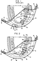
- Fig. 1 is a top plan view of the teeth of the lower jaw depicting the prior art forms in operative association with a dental dam;
- Fig. 2 is a top plan view of the teeth of the lower jaw depicting the elastomeric cord of the present invention employed in various methods and in operative association with a dental dam;
- Fig. 3 is a partial side elevational view of the teeth depicted in Fig. 2 taken substantially along line 3-3 of Fig. 2;
- Fig. 4A-4B are perspective views of the elastomeric cord of the present invention signifying the variance in size that may be employed;
- Fig 4C is a perspective view of the elastomeric cord of the present invention with a substantially annular cross-section;
- Fig. 4D is a perspective view of the elastomeric cord of the present invention with a substantially tear drop cross-section;
- Fig. 4E is a perspective view of the elastomeric cord of the present invention with a substantially square cross-section;
- Fig. 4F is a perspective view of the elastomeric cord of the present invention with a substantially triangular cross-section; and;
- Fig. 5 is a perspective view of the elastomeric cord of the present invention, partially elongated;
- Fig. 6 is a top plan view of the teeth of the lower jaw depicting the elastomeric cord of the present invention employed in a woven "in-and-out" fashion and in operative association with a dental dam;
- Fig. 7 is a perspective view of the webbed column created from the elastomeric cord of the present invention being viewed through a partial cut-away of the packaging box enveloping the column;
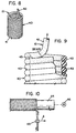
- Fig. 8 is an perspective view of the webbed column;
- Fig. 9 is an enlarged elevational view of a portion of the webbed column depicting first the web as it is broken upon the application of a force and also, in partial section, depicting the web as formed at the co-terminous boundary between windings; and
- Fig. 10 is an elevational view of the manufacturing process creating the webbed column depicting the uncured elastomeric cord in operative association with a mandrel and feeder.
-
- One representative form of a retention stabilizing means embodying the concepts of the present invention is designated generally by the
numeral 10 on the accompanying drawings. The representative stabilizingcord 10 is depicted in operative association with adental dam 11.Dental dam 11 comprises a flexible rubber sheet which can be stretched over aframe member 12. Such frames are known in the art as a Young frame and comprise acurved rim 13 that fits about the patient's jaw andopposed legs tongs 16 arc provided along theedge 18 thereof to engage thedam 11, which is stretched thereover. In the known art, depicted in Fig. 1, thedam 11 is retained over the teeth, in the patient's mouth by spring retainer clips 20 and 21.Clips contact prongs 22 that arc based against teeth e.g. molar M2 and canine tooth C1 where work is to be conducted on one or more of the teeth therebetween. Also depicted is a corner of rolleddental dam material 23, which has been wedged between molar M1 and premolar P2. - With respect to the present invention, stabilizing
cord 10 consists of a elastomeric, non-toxic strip of material such as natural rubber, thermoplastic elastomers and other high elongation, low hysteresis materials. A particularly useful material is natural rubber and is currently sold by the Assignee of record under the trademark WEDJETS. As best depicted in Fig.6, upon application of a tensile force to thecord 10, which is necessary in order for the cord to be more easily slidably placed between two juxtaposed teeth, the cross-sectional area decreases from a firstrelaxed area 24 to a secondelongated area 25. Generally, the decrease should be approximately 50 percent in diameter. Once the cord has been placed, the tensile force on ends 26 and 28 ofcord 10 may be released and thecross-sectional area 25 expands between the two said juxtaposed teeth. As shown in Fig. 3, the expandedcord 10 will fill the area between the two tooth crowns 29, and thegingival mucosa 30, thereby supplying a force upwards against both tooth crowns 29, and downward against thedental dam 11 effecting retention and stabilization of the dental dam. - The method of the present invention is employed because passing the dam through the proximal tooth contact point is insufficient to secure the dam on the anchor tooth. With reference to Fig. 2, an exemplary embodiment is presented. Specifically, a section of
cord member 10 is elongated by stretching and then interposed between molars M3 and M2 by urging downwardly therebetween. Upon release ofcord 10, it expands from its secondcross-sectional area 25 toward its first, greatercross-sectional area 24, which will not readily be dislodged from between the teeth, as clearly depicted in Fig. 3. A second section ofcord 10 is interposed around canine tooth C1, as an alternative placement technique, following which, operation on any of the teeth therebetween can be conducted. - It is also to be noted that the present invention may be utilizing in most all tooth spacing arrangements inasmuch as differing diameters of the cord can be provided to fill larger or smaller tooth spaces as shown in Figs. 4A and 4B. An exemplary embodiment is depicted in Fig. 3. The space between premolar P2 and molar M1 is narrow and, as a result, narrow cord 10A is employed. However, the space between molar M1 and M2 is larger requiring a cord with a larger cross-sectional area 10B to stabilize the
dental dam 11. - In the event the largest diameter is still loose and the space appears more as a diastema, the
cord 10 can be slidably interposed between two teeth, then, turned back upon itself and interposed between the same two juxtaposed teeth as shown in Figs. 2 and 3 between premolars P1 and P2. A second anchor method that may be employed is depicted in Fig.2 wherecord 10 encircles canine tooth C1 and after anchoring thedental dam 11 between premolar P1 and C1 a secondary anchor is created between the proximal side of canine tooth C1 and the distal side of incisor tooth I1. Cord 10 is then again interposed between P1 and C1. The effect of this anchor method is to maintain a double anchor between premolar P1 and canine tooth C1 while maintaining a secondary anchor between C1 and Incisor I1. - As is also depicted in Figs. 2 and 3, the cord can be looped over and doubled over on itself between adjacent teeth (P1 and P2), depending upon the desires of the practitioner. Furthermore, a longer section could be "woven" in an in-and-out fashion between a plurality of teeth in the area of the mouth to be treated by the practitioner. As depicted in Fig. 6, after the
dental dam 11 has been positioned over the teeth, a length ofcord 10 is interposed between the first two teeth, I1 and C1 and is then past around the lingual (or buccal) side of C1 to be interposed between the next two adjacent teeth, C1 and P1, this time being "woven" around the opposite, or buccal side of P1. The practitioner continues the procedure in an alternating fashion between each two subsequent and adjacent teeth until reaching the last tooth of the area (M2). At this tooth, the cord is encircled and is then re-interposed on opposite sides of the teeth, partially encircled during the first, alternating weave until the second tooth C1, of said first two teeth has been encircled. - The practitioner may wish to utilize this method to provide a second moisture barrier. The cord would then act as a gasket eliminating any water that may creep up the tooth, past the dental dam, and into the work area. A second reason one may wish to utilize this method would be where extra retention is needed to complete the operation. This could be particularly true, for a patient with a diastema between many consecutive juxtaposed teeth.
- Thus, it should be apparent to one skilled in the art that the use of stabilizing
cord 10 can best be decided by the dentist at the time of the operative procedure, as each mouth will present different circumstances. Furthermore, it is to be understood that each newmethod employing cord 10 would fall within the scope of the present invention. However, the present invention cannot be employed if the area to be retained does not contain two juxtaposed teeth between which stabilizingcord 10 may be placed, as shown at 31 in Fig. 2. - The
cord 10, being elastomeric, will reduce injury of thegingival tissue 30 because the tissue will force thecord 10 to deform, thereby applying pressure on thecord 10, instead of thecord 10 applying pressure on thetissue 30. However, to eliminate further any possible damage totissue 30, various shapes can be employed. With reference to Figs. 4D-4F, teardrop 10D, square 10E, and triangular 10F cross-sectional profiles are depicted. Such shapes will provide abody portion section 35 to extend and fill the gap between two juxtaposed teeth while providing anarrow trailing edge 36 for gingival tissue contact. Thenarrow trailing edge 36 will apply less pressure to thetissue 30 thereby causing less damage. - A further cross-section that may be employed further to eliminate any possible damage to
tissue 30 is depicted in Fig. 4C and takes the form of a hollow or tubular filament 10C. Although an annular cross-section is depicted, it should be apparent that any of the aforementioned cross-sectional areas can be formed such that an axial cavity extends therethrough. The hollow stabilizing cord may be employed to provide a still narrower cross section. - Referring to Fig. 5, when a tensile force is applied to ends 26 and 28 of
cord 10, for instance, a secondnarrower cross section 25 results. While actual diameters or cross sectional dimensions can vary, depending upon the needs of the practitioncr, generally the narrower cross section should be up to about one-third of the relaxed, unelongated section of cord. This is true for solid cord, irrespective of the shape. For hollow cords, the ratio between relaxed and elongated dimensions may be greater. - Thus, when the cord itself is hollow, a
narrower cross section 25 is provided than where cord is solid, thereby providing a stabilizing cord for employment between two juxtaposed teeth that are very close to each other. In conjunction with this benefit, it can be seen that because the cord is hollow, once it expands between the teeth, the same original cross section is provided on either side of the tooth. The hollow cord then allows for the cord to fit between closer teeth while still providing for full retention upon expansion. The hollow cord may also provide for a more forgiving cord to be utilized when the patient's mouth is abnormally sensitive. Having less material, the hollow cord will more easily be deformed. As a result, when the hollow cord is placed between two juxtaposed teeth, it will more readily deform thereby imparting less stress on the gingiva tissue. A third advantage is that because the cord will more easily be deformed, it will more readily accept the shape of the area between the teeth thereby acting to create a second, better, watertight seal. - A further advantage of the present system is that the
cord 10, whether hollow or solid, provides a retention system that is completely non-obtrusive in the work area. That is, once the dam is in place, the cord length can be adjusted by cutting away excesses so that only the cord between the teeth is acting to retain the dam with no extension into the work area. This differs from the prior art in that dam clamps 21 and 22 and thecut dam corner 23 extend into the work area. - Yet another advantage of the present system is the ease of employment. An assistant can easily insert the dental dam with the present invention as no skilled knotmaking is required. Furthermore, the patient does not need to be anesthetized to employ the present invention as with retention clamps of the prior art.
- While the present invention provides an improvement in the field of dentistry, it is equally important for the cord to be readily dispensable from a convenient container. Generally, when the cord is randomly placed in a container and pulled through an aperture therein, the cord may twist or bind, possibly prohibiting further withdrawal. To eliminate the aforementioned problem, the cord is provided in a novel form, depicted in Figs. 8 and 9. Specifically, the
cord 10 is formed into a helical cylinder orcolumn 40 which provides a single diameter of cord, coiled upon itself, and having a base 41 and afree end 42. As is apparent in Fig. 9, the helical configuration ofcolumn 40 provides a pitch substantially equal to the cord diameter, thereby defining a plurality of contiguous windings. At the juncture of each adjacent surface is aweb 43, (Fig. 9) which holds the cord together in its columnar configuration. - With reference to Fig. 10, manufacture of the
cord column 40 is schematically depicted. Thecord 10, in its uncured state, is wound onto amandrel 44. The cord is first fed onto themandrel 44 through afeeder 45. As thefeeder 45 slowly moves in the direction of arrow A,mandrel 44 is rotated by amotor 46 and thecord 10 is wound around the mandrel at a rate whereby each winding has a pitch substantially equal to the cord diameter. Once the cord is wound onto themandrel 44, it is heated and allowed to cool. Upon cooling, each successive winding will adhere to the windings adjacent thereto, thereby creating a coil, orcolumn 40. The windings adhere to each other in the manner previously described in Fig. 10, to form theweb 43 which is created when the material cures. The web inhibits the unwinding of the column which can then be removed from themandrel 44 and cut into a freestanding unit of predetermined length, again as depicted in Fig. 8. - The coil or
column 40 is then placed inside of astandard container 50 having a base 51, sides 52, top 53 andremovable cover 54. Anaperture 55 is provided in the top 53, or in the center (not shown) or out one of the sides 52 (also not shown). Ametal cutter 56 can be carried by the top 53 to sever predetermined lengths ofcord 10. - The
free end 42 as fed through theaperture 55 for withdrawal of the cord fromcolumn 40. During use, a tensile force sufficient to break the web bond at 58 will be applied and as it is applied, the web will continue to pull apart thereby freeing the top winding of thecolumn 40 so that it can be pulled throughaperture 55 without binding. Thecolumn 40 may rotate within the container, although this is not a necessary condition. While the present embodiment depicts the aperture in the edge of thecontainer top 53, it should be apparent to one skilled in the art that the aperture may be placed in any position on the container that allows for the material to be drawn off the top of thecolumn 40. - It should be appreciated that the
column 40 could be formed via other techniques including but not limited to the use of volatile solvents, adhesives compositions and the like so as to provide the necessary integrity to form a column and a tearing action of thefree end 42 from thecolumn 40. It should also be apparent that while the present exemplary embodiment depicts the coil created from a cord having a circular-cross section, any cross-section may be employed without departing from the spirit of the present invention. - Based upon the foregoing description, it should be apparent that a method and elastomeric cord embodying the concepts of the present invention effectively secure the dental dam in place. It should also be apparent to one skilled in the art that the cross-sectional shape and area may be altered beyond that which has been discussed herein. The cord is not limited to a particular rubber composition; nor, is the manufacture of the column limited to the methods disclosed herein. Finally, it is to be understood that the dispensing container can be varied provided that it remains operable with the
cord 10.
Claims (6)
- Dental apparatus comprising: a dental dam (11) adapted to be positioned over a plurality of teeth in the mouth of a patient; a frame to which the dental dam may be secured in use; and elastomeric material (10) to be located between adjacent teeth to hold the dam in position characterised in that the elastomeric material is in the form of an elastomeric cord (10) which can be stretched separately from the dam to reduce the cross sectional area thereof and thereby allow the stretched material to pass between adjacent teeth to a use location on the face of the dam remote from the gum after the dental dam has been positioned over the teeth; and the apparatus includes elastomeric cords with a range of different diameters for the purpose of allowing a cord of the correct diameter to be chosen in accordance with the space between the teeth into which the cord is to be introduced.
- A dental dam according to claim 1 characterised in that the elastomeric cord (10) is of natural rubber.
- A dental dam according to claim 1 or claim 2 characterised in that the cord permits elastic elongation thereof until the decrease in its cross-sectional area is approximately 50% of its relaxed diameter.
- A dental dam according to any preceding claim characterised in that the elastomeric cord is woven in an in-an-out fashion between a plurality of teeth.
- A dental dam according to any preceding claim characterised in that the elastomeric cord is of circular cross-section or of tear-drop cross-section or of square cross-section or of triangular cross-section.
- A dental dam according to any of claims I to 4 characterised in that the elastomeric cord is a hollow or tubular filament.
Priority Applications (1)
| Application Number | Priority Date | Filing Date | Title |
|---|---|---|---|
| EP00118206A EP1060711A3 (en) | 1990-09-06 | 1991-09-02 | A method of retaining a dental dam |
Applications Claiming Priority (2)
| Application Number | Priority Date | Filing Date | Title |
|---|---|---|---|
| US578424 | 1990-09-06 | ||
| US07/578,424 US5104317A (en) | 1990-09-06 | 1990-09-06 | Elastomeric cord for retaining a dental dam, cord dispenser and related combinations and methods |
Related Child Applications (1)
| Application Number | Title | Priority Date | Filing Date |
|---|---|---|---|
| EP00118206A Division EP1060711A3 (en) | 1990-09-06 | 1991-09-02 | A method of retaining a dental dam |
Publications (3)
| Publication Number | Publication Date |
|---|---|
| EP0475651A2 EP0475651A2 (en) | 1992-03-18 |
| EP0475651A3 EP0475651A3 (en) | 1992-06-10 |
| EP0475651B1 true EP0475651B1 (en) | 2001-12-05 |
Family
ID=24312832
Family Applications (2)
| Application Number | Title | Priority Date | Filing Date |
|---|---|---|---|
| EP91308022A Expired - Lifetime EP0475651B1 (en) | 1990-09-06 | 1991-09-02 | Elastomeric cord with the dental dam |
| EP00118206A Withdrawn EP1060711A3 (en) | 1990-09-06 | 1991-09-02 | A method of retaining a dental dam |
Family Applications After (1)
| Application Number | Title | Priority Date | Filing Date |
|---|---|---|---|
| EP00118206A Withdrawn EP1060711A3 (en) | 1990-09-06 | 1991-09-02 | A method of retaining a dental dam |
Country Status (5)
| Country | Link |
|---|---|
| US (1) | US5104317A (en) |
| EP (2) | EP0475651B1 (en) |
| AT (1) | ATE209876T1 (en) |
| CA (1) | CA2050750C (en) |
| DE (1) | DE69132846T2 (en) |
Families Citing this family (22)
| Publication number | Priority date | Publication date | Assignee | Title |
|---|---|---|---|---|
| US5499917A (en) * | 1993-06-29 | 1996-03-19 | Minnesota Mining And Manufacturing Company | Dental isolation dam |
| US5540588A (en) * | 1994-11-02 | 1996-07-30 | Earle; Jeffrey O. | Teflon-coated intraoral tissue retraction cord |
| WO1996039984A1 (en) * | 1995-06-07 | 1996-12-19 | The Hygenic Corporation | Device and method for retaining a dental dam |
| US5803734A (en) * | 1996-12-23 | 1998-09-08 | Knutson; Eric J. | Dental dam support and method of use |
| US6309221B1 (en) | 2000-10-13 | 2001-10-30 | Ultradent Products, Inc. | Compositions, methods and kits for hemostasis and sealing of pulp during invasive dental procedures |
| US7331788B2 (en) * | 2004-12-16 | 2008-02-19 | Kerrhawe Sa | Clamping cord with polymeric wedge component, and method of affixation |
| US8047843B2 (en) | 2006-09-13 | 2011-11-01 | Clark David J | Matrix stabilizer devices and a seamless, single load cavity preparation and filling technique |
| WO2008037250A1 (en) * | 2006-09-28 | 2008-04-03 | Center For Odontological Developments Aps | Preformed dentistry matrix band |
| US8641419B2 (en) * | 2007-07-25 | 2014-02-04 | David J. Clark | Methods and devices for fixed dental restoration |
| WO2009042957A2 (en) * | 2007-09-26 | 2009-04-02 | Indentiv, Llc | Methods, devices, systems, assemblies, and kits for tissue retraction in an oral cavity |
| US8393897B2 (en) * | 2007-11-07 | 2013-03-12 | David J. Clark | Methods and devices for diastema closure |
| US20090191506A1 (en) | 2008-01-29 | 2009-07-30 | Clark David J | Dental Composite Dispenser For Injection Molded Filling Techniques |
| US8376744B2 (en) * | 2008-09-09 | 2013-02-19 | Lon Jude Latiolais | Rotary gingival cord packer |
| US8535058B1 (en) * | 2010-01-28 | 2013-09-17 | Pulpdent Corporation | Dental release agent and methods for its use |
| AU2012290053B2 (en) * | 2011-08-02 | 2015-02-26 | Ultradent Products, Inc. | Retraction cord dispenser |
| US9358080B2 (en) | 2012-03-26 | 2016-06-07 | David J. Clark | Dental separator ring |
| CN108888305B (en) | 2013-03-15 | 2022-11-04 | 美国皓齿制品有限公司 | Cheek retraction device and method |
| USD737964S1 (en) | 2014-03-14 | 2015-09-01 | Ultradent Products, Inc. | Cheek retractor device |
| USD763444S1 (en) | 2014-03-14 | 2016-08-09 | Ultradent Products, Inc. | Cheek retractor device |
| USD792590S1 (en) | 2015-07-21 | 2017-07-18 | Ultradent Products, Inc. | Cheek retractor device |
| CN109275590A (en) * | 2017-07-19 | 2019-01-29 | 长沙市公安局刑事侦查支队 | A kind of instruction dog device |
| USD914214S1 (en) | 2019-06-03 | 2021-03-23 | Ultradent Products, Inc. | Dental retraction device |
Family Cites Families (12)
| Publication number | Priority date | Publication date | Assignee | Title |
|---|---|---|---|---|
| US484046A (en) * | 1892-10-11 | Rubber dam | ||
| US806300A (en) * | 1905-05-27 | 1905-12-05 | James Sorenson | Dental-ligature applier. |
| US1031533A (en) * | 1912-02-21 | 1912-07-02 | T P Davie | Dental appliance. |
| US1973615A (en) * | 1931-07-17 | 1934-09-11 | Kendall & Co | Dispensing package for absorbent cotton or the like |
| US2782503A (en) * | 1953-08-21 | 1957-02-26 | Lyman F Thompson | Interproximal stops for preventing filling overhang into the interproximal space between teeth |
| US3238620A (en) * | 1961-06-22 | 1966-03-08 | Lyle C Robertson | Method of preparing an impression of a tooth |
| US3795052A (en) * | 1972-06-05 | 1974-03-05 | L Mowery | Self-shaping dental matrix |
| US4215477A (en) * | 1977-04-25 | 1980-08-05 | Shanel Kathleen A | Holder for rubber dental dam |
| US4261697A (en) * | 1980-02-15 | 1981-04-14 | Newitter David A | Evacuating rubber dam frame |
| DE3122834A1 (en) * | 1980-07-24 | 1982-12-23 | Herschel, Udo, 5110 Alsdorf | Retention gingival thread for dental impressions |
| US4465462A (en) * | 1983-04-27 | 1984-08-14 | Ticknor Verne E | Gingival retraction cord |
| US4522593A (en) * | 1983-07-07 | 1985-06-11 | Fischer Dan E | Knitted gingival retraction cord |
-
1990
- 1990-09-06 US US07/578,424 patent/US5104317A/en not_active Expired - Lifetime
-
1991
- 1991-09-02 AT AT91308022T patent/ATE209876T1/en active
- 1991-09-02 DE DE69132846T patent/DE69132846T2/en not_active Expired - Lifetime
- 1991-09-02 EP EP91308022A patent/EP0475651B1/en not_active Expired - Lifetime
- 1991-09-02 EP EP00118206A patent/EP1060711A3/en not_active Withdrawn
- 1991-09-05 CA CA002050750A patent/CA2050750C/en not_active Expired - Lifetime
Also Published As
| Publication number | Publication date |
|---|---|
| EP1060711A3 (en) | 2004-03-03 |
| EP0475651A2 (en) | 1992-03-18 |
| US5104317A (en) | 1992-04-14 |
| CA2050750C (en) | 2003-11-11 |
| CA2050750A1 (en) | 1992-03-07 |
| EP0475651A3 (en) | 1992-06-10 |
| DE69132846D1 (en) | 2002-01-17 |
| EP1060711A2 (en) | 2000-12-20 |
| ATE209876T1 (en) | 2001-12-15 |
| DE69132846T2 (en) | 2002-04-18 |
Similar Documents
| Publication | Publication Date | Title |
|---|---|---|
| US5104317A (en) | Elastomeric cord for retaining a dental dam, cord dispenser and related combinations and methods | |
| US6482005B1 (en) | Method and apparatus for shaping dental filling material | |
| US5425635A (en) | Matrix band segment and restoration procedure | |
| US5803734A (en) | Dental dam support and method of use | |
| US5382160A (en) | Dental matrix with retention and locking mechanism | |
| US5520921A (en) | Periodontal packing device | |
| US6482007B2 (en) | Dental wedge with handle | |
| JP2004525707A (en) | General field isolation rubber dam | |
| US8272869B2 (en) | Dental matrix | |
| WO1989009032A1 (en) | Unitary preassembled disposable intra-oral rubber dam device | |
| US20190231476A1 (en) | Dental separator and matrix system for producing dental restorations | |
| US7083412B1 (en) | Dental tooth spacer assembly | |
| JP2004519316A (en) | Rubber dam | |
| CN106691606A (en) | A dental wedge | |
| Reuter | The isolation of teeth and the protection of the patient during endodontic treatment. | |
| US5720611A (en) | Long-armed type uprighting spring for molar tooth | |
| US10299893B2 (en) | Method and apparatus for slow palate expansion | |
| US20060019217A1 (en) | Anterior composite matrix dental restoration system | |
| US11490993B2 (en) | Elastic matrix band | |
| US3411214A (en) | Dental appliance | |
| US20040152039A1 (en) | Dental adhesive strip | |
| EP1671603B1 (en) | Clamping cord with polymeric wedge component | |
| WO1996039984A1 (en) | Device and method for retaining a dental dam | |
| US5030092A (en) | Method and apparatus for temporary attachment of a safety line to dental restorations and appliances | |
| US7465167B2 (en) | Method and device for positioning gum line about dental replacement teeth surfaces |
Legal Events
| Date | Code | Title | Description |
|---|---|---|---|
| PUAI | Public reference made under article 153(3) epc to a published international application that has entered the european phase |
Free format text: ORIGINAL CODE: 0009012 |
|
| AK | Designated contracting states |
Kind code of ref document: A2 Designated state(s): AT BE CH DE DK ES FR GB GR IT LI LU NL SE |
|
| PUAL | Search report despatched |
Free format text: ORIGINAL CODE: 0009013 |
|
| AK | Designated contracting states |
Kind code of ref document: A3 Designated state(s): AT BE CH DE DK ES FR GB GR IT LI LU NL SE |
|
| 17P | Request for examination filed |
Effective date: 19921110 |
|
| 17Q | First examination report despatched |
Effective date: 19940624 |
|
| RAP1 | Party data changed (applicant data changed or rights of an application transferred) |
Owner name: COLTENE/WHALEDENT, INC. |
|
| GRAG | Despatch of communication of intention to grant |
Free format text: ORIGINAL CODE: EPIDOS AGRA |
|
| RTI1 | Title (correction) |
Free format text: ELASTOMERIC CORD WITH THE DENTAL DAM |
|
| GRAG | Despatch of communication of intention to grant |
Free format text: ORIGINAL CODE: EPIDOS AGRA |
|
| GRAH | Despatch of communication of intention to grant a patent |
Free format text: ORIGINAL CODE: EPIDOS IGRA |
|
| GRAH | Despatch of communication of intention to grant a patent |
Free format text: ORIGINAL CODE: EPIDOS IGRA |
|
| GRAA | (expected) grant |
Free format text: ORIGINAL CODE: 0009210 |
|
| AK | Designated contracting states |
Kind code of ref document: B1 Designated state(s): AT BE CH DE DK ES FR GB GR IT LI LU NL SE |
|
| PG25 | Lapsed in a contracting state [announced via postgrant information from national office to epo] |
Ref country code: LI Free format text: LAPSE BECAUSE OF FAILURE TO SUBMIT A TRANSLATION OF THE DESCRIPTION OR TO PAY THE FEE WITHIN THE PRESCRIBED TIME-LIMIT Effective date: 20011205 Ref country code: BE Free format text: LAPSE BECAUSE OF FAILURE TO SUBMIT A TRANSLATION OF THE DESCRIPTION OR TO PAY THE FEE WITHIN THE PRESCRIBED TIME-LIMIT Effective date: 20011205 Ref country code: GR Free format text: LAPSE BECAUSE OF FAILURE TO SUBMIT A TRANSLATION OF THE DESCRIPTION OR TO PAY THE FEE WITHIN THE PRESCRIBED TIME-LIMIT Effective date: 20011205 Ref country code: CH Free format text: LAPSE BECAUSE OF FAILURE TO SUBMIT A TRANSLATION OF THE DESCRIPTION OR TO PAY THE FEE WITHIN THE PRESCRIBED TIME-LIMIT Effective date: 20011205 Ref country code: AT Free format text: LAPSE BECAUSE OF FAILURE TO SUBMIT A TRANSLATION OF THE DESCRIPTION OR TO PAY THE FEE WITHIN THE PRESCRIBED TIME-LIMIT Effective date: 20011205 |
|
| REF | Corresponds to: |
Ref document number: 209876 Country of ref document: AT Date of ref document: 20011215 Kind code of ref document: T |
|
| REG | Reference to a national code |
Ref country code: CH Ref legal event code: EP |
|
| REG | Reference to a national code |
Ref country code: GB Ref legal event code: IF02 |
|
| REF | Corresponds to: |
Ref document number: 69132846 Country of ref document: DE Date of ref document: 20020117 |
|
| PG25 | Lapsed in a contracting state [announced via postgrant information from national office to epo] |
Ref country code: DK Free format text: LAPSE BECAUSE OF FAILURE TO SUBMIT A TRANSLATION OF THE DESCRIPTION OR TO PAY THE FEE WITHIN THE PRESCRIBED TIME-LIMIT Effective date: 20020305 |
|
| ET | Fr: translation filed | ||
| REG | Reference to a national code |
Ref country code: CH Ref legal event code: PL |
|
| PG25 | Lapsed in a contracting state [announced via postgrant information from national office to epo] |
Ref country code: ES Free format text: LAPSE BECAUSE OF FAILURE TO SUBMIT A TRANSLATION OF THE DESCRIPTION OR TO PAY THE FEE WITHIN THE PRESCRIBED TIME-LIMIT Effective date: 20020627 |
|
| PG25 | Lapsed in a contracting state [announced via postgrant information from national office to epo] |
Ref country code: LU Free format text: LAPSE BECAUSE OF NON-PAYMENT OF DUE FEES Effective date: 20020902 |
|
| PLBE | No opposition filed within time limit |
Free format text: ORIGINAL CODE: 0009261 |
|
| STAA | Information on the status of an ep patent application or granted ep patent |
Free format text: STATUS: NO OPPOSITION FILED WITHIN TIME LIMIT |
|
| 26N | No opposition filed | ||
| PGFP | Annual fee paid to national office [announced via postgrant information from national office to epo] |
Ref country code: FR Payment date: 20100930 Year of fee payment: 20 |
|
| PGFP | Annual fee paid to national office [announced via postgrant information from national office to epo] |
Ref country code: GB Payment date: 20100927 Year of fee payment: 20 |
|
| PGFP | Annual fee paid to national office [announced via postgrant information from national office to epo] |
Ref country code: NL Payment date: 20100924 Year of fee payment: 20 |
|
| PGFP | Annual fee paid to national office [announced via postgrant information from national office to epo] |
Ref country code: DE Payment date: 20100929 Year of fee payment: 20 |
|
| PGFP | Annual fee paid to national office [announced via postgrant information from national office to epo] |
Ref country code: IT Payment date: 20100927 Year of fee payment: 20 Ref country code: SE Payment date: 20100929 Year of fee payment: 20 |
|
| REG | Reference to a national code |
Ref country code: DE Ref legal event code: R071 Ref document number: 69132846 Country of ref document: DE |
|
| REG | Reference to a national code |
Ref country code: DE Ref legal event code: R071 Ref document number: 69132846 Country of ref document: DE |
|
| REG | Reference to a national code |
Ref country code: NL Ref legal event code: V4 Effective date: 20110902 |
|
| REG | Reference to a national code |
Ref country code: GB Ref legal event code: PE20 Expiry date: 20110901 |
|
| REG | Reference to a national code |
Ref country code: SE Ref legal event code: EUG |
|
| PG25 | Lapsed in a contracting state [announced via postgrant information from national office to epo] |
Ref country code: GB Free format text: LAPSE BECAUSE OF EXPIRATION OF PROTECTION Effective date: 20110901 |
|
| PG25 | Lapsed in a contracting state [announced via postgrant information from national office to epo] |
Ref country code: NL Free format text: LAPSE BECAUSE OF EXPIRATION OF PROTECTION Effective date: 20110902 |
|
| PG25 | Lapsed in a contracting state [announced via postgrant information from national office to epo] |
Ref country code: DE Free format text: LAPSE BECAUSE OF EXPIRATION OF PROTECTION Effective date: 20110903 |