EP0475464A2 - Block coded modulation system - Google Patents
Block coded modulation system Download PDFInfo
- Publication number
- EP0475464A2 EP0475464A2 EP91119521A EP91119521A EP0475464A2 EP 0475464 A2 EP0475464 A2 EP 0475464A2 EP 91119521 A EP91119521 A EP 91119521A EP 91119521 A EP91119521 A EP 91119521A EP 0475464 A2 EP0475464 A2 EP 0475464A2
- Authority
- EP
- European Patent Office
- Prior art keywords
- signal
- signals
- bits
- block
- constellation
- Prior art date
- Legal status (The legal status is an assumption and is not a legal conclusion. Google has not performed a legal analysis and makes no representation as to the accuracy of the status listed.)
- Granted
Links
Images


Classifications
-
- H—ELECTRICITY
- H03—ELECTRONIC CIRCUITRY
- H03M—CODING; DECODING; CODE CONVERSION IN GENERAL
- H03M13/00—Coding, decoding or code conversion, for error detection or error correction; Coding theory basic assumptions; Coding bounds; Error probability evaluation methods; Channel models; Simulation or testing of codes
- H03M13/25—Error detection or forward error correction by signal space coding, i.e. adding redundancy in the signal constellation, e.g. Trellis Coded Modulation [TCM]
- H03M13/251—Error detection or forward error correction by signal space coding, i.e. adding redundancy in the signal constellation, e.g. Trellis Coded Modulation [TCM] with block coding
-
- H—ELECTRICITY
- H04—ELECTRIC COMMUNICATION TECHNIQUE
- H04L—TRANSMISSION OF DIGITAL INFORMATION, e.g. TELEGRAPHIC COMMUNICATION
- H04L27/00—Modulated-carrier systems
- H04L27/32—Carrier systems characterised by combinations of two or more of the types covered by groups H04L27/02, H04L27/10, H04L27/18 or H04L27/26
- H04L27/34—Amplitude- and phase-modulated carrier systems, e.g. quadrature-amplitude modulated carrier systems
- H04L27/3405—Modifications of the signal space to increase the efficiency of transmission, e.g. reduction of the bit error rate, bandwidth, or average power
- H04L27/3416—Modifications of the signal space to increase the efficiency of transmission, e.g. reduction of the bit error rate, bandwidth, or average power in which the information is carried by both the individual signal points and the subset to which the individual points belong, e.g. using coset coding, lattice coding, or related schemes
- H04L27/3427—Modifications of the signal space to increase the efficiency of transmission, e.g. reduction of the bit error rate, bandwidth, or average power in which the information is carried by both the individual signal points and the subset to which the individual points belong, e.g. using coset coding, lattice coding, or related schemes in which the constellation is the n - fold Cartesian product of a single underlying two-dimensional constellation
- H04L27/3438—Modifications of the signal space to increase the efficiency of transmission, e.g. reduction of the bit error rate, bandwidth, or average power in which the information is carried by both the individual signal points and the subset to which the individual points belong, e.g. using coset coding, lattice coding, or related schemes in which the constellation is the n - fold Cartesian product of a single underlying two-dimensional constellation using an underlying generalised cross constellation
Definitions
- This invention relates to high-speed data transmission over band-limited channels, such as telephone lines.
- Modulation systems for such channels commonly use two-dimensional carrier modulation, generically called double-sideband-quadrature-carrier (DSB-QC) modulation.
- DSB-QC double-sideband-quadrature-carrier
- Conventional DSB-QC systems are used to send an integer number (N) of bits in each modulation interval of T seconds in a nominal bandwidth of 1/T Hz.
- N integer number
- some telephone line modems send 4 bits per modulation interval of 1/2400 sec. within a nominal bandwidth of 2400 Hz, thus achieving a 9600 bits per second (bps) data transmission rate.
- Modems for sending 6 bits per modulation interval to achieve 14,400 bps in a nominal 2400 Hz bandwidth are also available.
- Such DSB-QC systems use signal constellations of 2 N signals for sending N bits per modulation interval.
- a family of such constellations with signals arranged on a regular rectangular grid is described in Campopiano and Glazer, "A Coherent Digital Amplitude and Phase Modulation Scheme," IRE Transactions on Communication Systems, Vol. CS-9, pp. 90-95, March 1962, incorporated herein by reference.
- Fig. 1 shows the arrangement of signals in the Campopiano and Glazer constellations and the outer boundaries of those constellations for values of N from 4 through 8.
- Table I shows the so-called "required signal-to-noise ratio" P ⁇ (defined in Campopiano et al. and in the Forney/Gallager patent) for the constellations of Fig. 1.
- P ⁇ defined in Campopiano et al. and in the Forney/Gallager patent
- Each unit increase in N corresponds to an increase in required signal-to-noise ratio of about a factor of two or 3.0 decibels (dB).
- coded modulation techniques can provide improved resistance to noise and other channel impairments; that is, they can provide a reduction in required signal-to-noise ratio, or a so-called "coding gain”.
- the N bits appearing in each modulation interval are individually mapped into signal points selected from a constellation of 2 N+1 signals.
- the signals in the constellation are organized into subsets such that the minimum distance between two signals belonging to one subset is greater than the minimum distance between any two signals in the constellation.
- the selection of the signal point for each N input bits is made to depend, in part, on the historical sequence of all previously selected signal points, as represented by the state of a finite state device in the encoder.
- This so-called trellis coding effectively permits only certain sequences of signal points to be transmitted, and the coded historical information carried by every signal point is exploited at the receiver by a maximum likelihood sequence estimation technique (e.g., one based on the Viterbi algorithm, as described in Forney, "The Viterbi Algorithm,” Proceedings of the IEEE, Vol. 61, pp. 268-278, March, 1973, incorporated herein by reference).
- m signal points are selected from a constellation having more than 2 N signals, a process which is equivalent to mapping each block into a code word selected from an available code word set of 2 n code words arranged in 2m-dimensional space (called simply 2m-space), with the 2m coordinates of each code word, taken two at a time, defining the respective pair of coordinates in two-dimensional space of the m signal points to be selected.
- the code word set from which the code word for any block may be drawn is independent of the signal points selected for any other block.
- the decisions on which signal points were sent are based on the received signal points for each block (the so-called received word), preferably using maximum likelihood decoding.
- One method of block coding involves using a code word set arranged on a finite portion of a densely packed infinite geometrical lattice in 2m-space; see, for example, Conway and Sloane, "Fast Quantizing and Decoding Algorithms for Lattice Quantizers and Codes," IEEE Transactions on Information Theory, Vol. IT-28, pp. 227-232, March 1982, and the references cited therein, incorporated herein by reference.
- a representative system of this type is disclosed in "Block Coding for Improved Modem Performance," a Canadian contribution (Com XVII-No.
- the invention includes a family of block coded modulation systems of progressively greater complexity exhibiting progressively greater coding gain over uncoded systems.
- the invention features, in such block coded modulation systems, the improvement in which the signal constellation includes groups having equal numbers of signals, and the encoder is arranged so that the group from which at least one signal point for a block is drawn depends on the group from which at least one other signal point for the block is drawn, whereby a coding gain over uncoded systems is achieved.
- the signals are arranged (e.g., on a rectangular grid) so that the minimum squared distance between two signals belonging to the same group is greater than (e.g., twice the distance) between two signals belonging to different groups;
- the signal points are two dimensional, the code words are 2m-dimensional, m being the number of signal points corresponding to each code word, and each block of digital data has mN bits;
- each block comprises a plurality of bits, and the groups from which the signal points for the block are drawn are determined by a single bit of the block;
- N is an integer, m is an even integer no smaller than 2, and the constellation has 1.5x2 N signals;
- N r+1/2, r being an integer, m is no smaller than 2, and the constellation comprises 2 r+1 signals;
- the encoder is further arranged so that m-1 signal points for each block may be drawn from among all signals in the constellation, and the one remaining signal point for the block is drawn from a group that depends (e.g., by means of a single-parity
- the groups each have subsets having equal numbers of signals
- the encoder is further arranged so that the subset from which at least one signal point for the block is drawn depends on the subset from which at least one other signal point for the block is drawn;
- the signals are arranged (e.g., on a rectangular grid) so that the minimum squared distance between two signals belonging to one subset is greater than (e.g., twice the distance) between two signals belonging to different subsets within the same group;
- the subsets from which the signal points for a block are drawn are determined based on a plurality of bits representing less than all of the digital data of the block;
- N is an integer, m is at least 4, and the constellation has 2 N+1 said signals;
- N r+1/2, r being an integer, m is an even integer no smaller than 4, and the constellation has 1.5x2 r+1 signals;
- the encoder is further arranged (e.g., by means of a single-parity-check code, a Hamming code, or a
- the subsets each comprise classes having equal numbers of signals
- the classes each comprise subclasses having equal numbers of signals
- the encoder is further arranged so that the subclass from which at least one signal point for the block is drawn depends on the subclass from which at least one other signal point for the block is drawn; the minimum squared distance between two signals belonging to one subclass is greater than (e.g., twice the distance) between two signals belonging to different subclasses within the same class; m is 12; N is an integer and the constellation has 2 N+2 signals; the subclasses from which the signal points for the block are drawn are determined by the encoder based on a Golay code applied to at least one of the bits; m is 12 and N is 4; and the subclasses from which the signal points for the block are drawn are determined based on a plurality of bits representing less than all of the digital data of the block.
- the constellation has quadruplets each having four signals located at the same distance from the origin but separated by 90° intervals about the origin, the digital data comprises bits, and at least two of the bits are quadrantally differentially encoded; the four signals belonging to each quadruplet are drawn from four different subsets; there is also a decoder arranged to decide which code word was sent based on maximum likelihood sequence estimation in accordance with the Viterbi algorithm; there is a demodulator having a decoder arranged to make tentative decisions about which signal point was sent prior to final decoding of all of the received signal points for a block, and the demodulator comprises adaptive control circuitry arranged to be responsive to the tentative decision; the signal points for each code word are drawn from the same group; the decoder is arranged to decide which code word was sent by first making a separate tentative decision based on code words whose signal points are drawn from each group, and thereafter a
- the invention features, in a modulation system for sending a block of digital data bits over a band-limited channel using a plurality of modulation signal points drawn from a two-dimensional constellation of available signals, the improvement in which the constellation has a plurality of inner signals, and a plurality of outer signals further from the origin than the inner signals, one bit of the digital data determines whether any of the plurality of signal points will be drawn from the outer signals, and if an outer signal will be drawn, at least one other bit of the digital data determines which of the plurality of signal points will be an outer signal point.
- the 4-space, 8-space, 16-space, and 24-space modulation systems of the invention respectively exhibit asymptotic coding gains of about 1.5, 3.0, 4.5, and 6.0 dB over uncoded systems that send the same number of bits per modulation interval through the same nominal bandwidth using DSB-QC modulation.
- the block coded systems of the invention are slightly inferior in performance to the best known prior art schemes (e.g., about .2 dB and .4 dB worse for 4-space and 8-space systems, respectively), but have substantial advantages in implementation.
- the invention uses constellations having relatively small numbers of signals.
- the encoding techniques are economical, simple, and easily implemented. Encoding delay is reduced because early signal points selected for a given block can be sent before encoding of the block has been completed.
- Decoding delay is small because received signal points can be finally decoded as soon as all signal points for a given block have been received. Useful tentative decoding decisions can be made even sooner. Non-integral numbers of bits per interval can be sent. Quadrantal differential encoding can be used to improve immunity to phase hits. Economical, simple, and easily implemented decoding techniques are made possible.
- Fig. 1 is a diagram of a family of five prior art signal constellations.
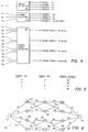
- Fig. 2 is a block diagram of modem apparatus.
- Fig. 3 is a diagram of a signal constellation in accordance with the preferred embodiment.
- Fig. 4 is a block diagram of the signal selection logic for the constellation of Fig. 3.
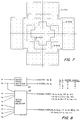
- Fig. 5 is a table showing the correspondence between input bits and signal subsets.
- Fig. 6 is a state-transition diagram (trellis) for use with the constellation of Fig. 3.
- Fig. 7 is a diagram of a family of four signal constellations in accordance with an alternate embodiment.
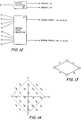
- Figs. 8, 12, 15, 17, and 20 are block diagrams of signal selection logic in accordance with alternate embodiments.
- Figs. 9, 10, 11, 14, 16, and 19 are diagrams of signal constellations in accordance with alternate embodiments.
- Figs. 18 and 21 are diagrams of the relationships of signal quadruplets in the constellations of Figs. 16 and 19, respectively.
- Figs. 13, 22, and 23 are trellises for use with alternate embodiments.
- 8-space block coded modulation systems an 8-space system sending 4 bits per modulation interval and achieving an asymptotic coding gain of 3.0 dB
- Alternative embodiments thereafter described are other decoding and encoding techniques for 8-space block coded modulation systems; 8-space block coded systems for sending any integral number of bits per modulation interval; multidimensional signal structures for sending a non-integral number of bits per modulation interval (useful in both coded and uncoded systems); 4-space, 16-space, 24-space, and 2m-space block coded systems; and other embodiments.
- an 8-space block coded modulation system for sending 4 bits per modulation interval
- a block of 16 bits is sent in each 4 modulation intervals using a signal constellation having 32 signals.
- the four subsets A0, A1, B0, B1 are arranged in two groups (A, comprising subsets A0 and A1, and B, comprising B0 and B1) of two subsets each.
- Signal selection logic 18 is arranged to select, for each block of input bits, a sequence of four signal points which are interdependent, i.e., the signal group and/or subset from which at least some of the signal points for a given block may be selected depends in part on at least one of the other signal points selected for that block.
- the code word set from among which the code word for a given block may be drawn is independent of the signal points selected for any other block.
- Each of the 32 constellation signals can be uniquely specified by a total of 5 bits: one bit naming the group from which it is taken, one bit naming the subset within that group, and three bits naming which of the eight signal points within the named subset is to be selected.
- the four signal points for a block could be uniquely specified by a total of 20 bits.
- the block has only 16 input bits on which to base the selections.
- the group, subset, and signal point selection information needed to select each of the four signal points for each block is derived from the 16 input bits (b1-b16) as follows.
- Group selector 32 uses bit b1 (called the group bit) to determine the one group from which all four signal points for a given block is to be drawn.
- group1 refers to the group from which the first signal point is selected; and so on.
- the subset bits can be viewed as coded bits derived by a (4, 3) single-parity-check code from the input bits b2-b4.
- the remaining bits (b5-b16) taken three at a time (called signal point bits) specify which particular four signal points (signal point1-signal point4) are to be drawn by signal point selector 36 from the selected 8-point subsets.
- group selector 32 and subset selector 34 assure that the group from which at least one of the signal points for a given block is selected depends on the group from which at least one of the other signal points for the block is selected (thereby reducing, after the first signal point, the number of groups from which later signal points for a block can be selected), and to assure that the subset from which at least one of the signal points is selected depends on the subset from which at least one of the other signal points is selected (thereby reducing, after the first signal point, the number of subsets from which later signal points for a block can be selected).
- the signal selection has been explained as the selection of four successive signal points from a 2-dimensional signal constellation, it could also be viewed as an 8-space block coded modulation technique in which a set of 216 code words are arranged on a lattice in 8-space, and coding consists of selecting one of the code words for each block. The eight coordinates of the selected code words could then be taken two at a time to specify the four two-dimensional signal points to be used for carrier modulation.
- That the minimum squared distance between code words in 8-space is 8 can be seen as follows. Two different code words which have the same group bit and the same subset bits must differ in at least one of their respective four signal points. Because those two different signal points must be drawn from the same subset, and signal points in the same subset have a minimum squared distance of 8 on the two-dimensional plane, the two code words in 8-space likewise have a minimum squared distance of 8.
- two code words which have the same group bit but different subset bits must differ in at least two of their subset bits (because the subset bits have even parity). At least two of their respective four signal points must therefore differ in each case by a minimum squared distance of 4 (the minimum squared distance on the two-dimensional plane between two signal points chosen from a given group) for a total minimum squared distance of 8.
- each code word has up to 240 nearest neighbors (16 which have the same group and subset bits, 96 which have the same group bits but different subset bits, and 128 which have different group and subset bits). But because code words near the outer boundary of the code word set have fewer neighbors, the average code word only has about 180 near neighbors.
- decoding of the four signal points into the corresponding bit stream is optimally done by maximum likelihood decoding, i.e., picking the one code word which is most likely to have been sent, given the 8-space received word determined by the four received two-dimensional signal points.
- the decoder tentatively finds (by conventional slicing in two-dimensional space) the closest (in Euclidean distance) signal from the A group and the closest signal from the B group to the received signal point, noting, on a running basis, which of the coordinates of the tentatively selected signals for each group is least reliable (i.e., has the greatest apparent error).
- the subset bits of the four tentatively selected A signals are checked for parity. If parity checks, then the four tentatively selected A signals define the closest code word in the A group to the received word.
- the closest A code word is found by changing the least reliable coordinate to the coordinate of the next closer A signal, which (because of the arrangement of the subset points in the constellation) will always cause a change of that signal from an A0 to an A1 signal (or vice versa), and thus yield a code word of correct parity.
- An analogous slicing and parity checking sequence finds the closest B code word to the received word.
- the final decoding decision entails choosing whether the previously determined closest A code word or closest B code word is closer (in overall Euclidean distance) to the received coordinates in 8-space.
- the choice may be made by computing the sum of the squared coordinate differences between each of the two code words and the received word and comparing the sums.
- Decoding thus requires only slicing (twice) in each coordinate, storing (for A and B code words respectively) the location and magnitude of the largest apparent error so far, accumulating the Euclidean distances for the best code words from each group, checking the parity of each best code word (and changing one coordinate in each code word, if needed, thereby changing the Euclidean distance for that word), and comparing the Euclidean distances for the resulting two best code words to select the better one.
- This decoding method may be readily and simply implemented (by conventional techniques) using a programmable microprocessor.
- the block coded modulation system can be made transparent to 90° phase rotations between the received carrier and the transmitted carrier using quadrantal differential coding on a block basis.
- the signal constellation of Fig. 3 is arranged in quadruplets of signals having the same radii but separated by 90° phase differences, each quadruplet having one signal from each subset, so that a 90° clockwise rotation translates, within each quadruplet, the A0 signal to the B0 signal, the B0 signal to the A1 signal, the A1 signal to the B1 signal, and the B1 signal to the A0 signal; and analogous translations occur for 180° and 270° rotations.
- the signals denoted 37 in Fig. 3 form such a quadruplet. Referring to Fig.
- Quadrantal differential coding can then be accomplished by assigning the same three signal point bits to all four of the signals within each quadruplet, and coding the subset and group bits for each signal point in a code word by differential four-phase coding, using for example the subset and group bits of the last signal point of the previous code word as the reference.
- (x1, x2) denotes the differentially encoded subset and group bits of the last signal point of the previous code word
- (y1, y2) denotes the subset and group bits of a signal point in the current code word (before differential encoding)
- both the previous and the current code words are correctly decoded (except for a possible phase rotation of an integral multiple of 90°).
- (y1, y2) is determined by subtracting (x1', x2') from (z1', z2') as two-bit integers, modulo four. The resulting (y1, y2) value will then be correct even if both (x1', x2') and (z1', z2') have been advanced by p modulo 4 as a result of a p x 90° phase rotation.
- transmission can begin as soon as five bits (b1, b2, b5, b6, b7) have been collected, thereby reducing the encoding delay which would exist for other kinds of block coding in which all of the bits of the block would have to be collected before encoding could begin.
- maximum likelihood decoding can be accomplished by applying the Viterbi algorithm (in a manner described in Forney's Viterbi article, cited above).
- the encoding process can be illustrated by a finite-length 4-state trellis 40.
- the trellis shows from left to right the state of the encoder at five successive times, beginning with a node 42 reflecting the time immediately before encoding of a new block begins and ending with a node 44 reflecting the time just after the encoding of that block has been completed.
- nodes 42, 44 In between nodes 42, 44 are shown four modulation intervals separated by three time instants, each such instant being represented by a column of four nodes 46 corresponding to the four states which the encoder can occupy at that instant.
- Branches 48 from each node to the next nodes to its right correspond to modulation intervals and reflect transitions of the state of the encoder which can occur as a signal point is selected.
- Each branch 48 is labeled with a letter to indicate the subset corresponding to the signal point associated with that modulation interval.
- the encoder begins at a common node 42 (reflecting that the encoder's state does not depend on historical information). From node 42 the encoder branches to one of four states depending on the group and subset bits of the first selected signal point. For example, if the first selected signal point is from subset A0, the next encoder state is at node 50. For the next two signal points, the encoder state stays in the half of the trellis defined by the group bit of the first signal point, but switches states (from one parity to the other) in accordance with the transitions shown. Only 16 of the 32 signals in the constellation are available for selection of the second and third signal.
- the transition to the final node 44 is determined by the parity state of the encoder (e.g., an A1 or B1 point is sent if the parity state is 1, otherwise an A0 or B0 point is sent).
- the parity state of the encoder e.g., an A1 or B1 point is sent if the parity state is 1, otherwise an A0 or B0 point is sent.
- Only a subset of 8 of the 32 signals in the constellation are available for selection of the fourth signal point, and that subset depends on the first three selected signal points.
- the paths through the trellis define the possible combinations of subsets from which the sequence of four signal points for each block can be chosen.
- each received word in accordance with the Viterbi algorithm, decisions are first made (using conventional slicing in two dimensions, with the coordinate axes rotated 45°) of which of the eight signals in each of the four subsets is closest to each received signal point.
- a branch in trellis 40 (corresponding to each subset) is then associated with the closest signal in its corresponding subset, and the so-called metric of each branch is the squared distance between the received signal point and the corresponding closest signal associated with that branch.
- the remaining steps of the Viterbi algorithm decoding proceed as described in Forney's Viterbi article, cited above.
- a final decoding decision is possible after four modulation intervals, at which time all trellis branches converge to a single node 44.
- the input bits may be coded (using a Hamming code) into coded bits which are used to select the subsets from which the signal points may be selected.
- the minimum squared distance between code words in 8-space is then 8.
- two code words correspond to different Hamming coded bits z1-z8, then these bits differ in at least 4 places, which (because the Hamming distance is half the subset distance, as just described) implies that the squared distance between the code words is at least 8.
- two code words corresponding to the same Hamming coded bits z1-z8 have signal points all in the same subsets in each modulation interval; in at least one interval the signal points must be different, and since they belong to the same subset the minimum squared distance between them is 8.
- the selection of the four subsets to be used in the four modulation intervals can be done by any method (in addition to the three already described) which produces minimum squared distance of 8 between code words (based on the distance properties of the subsets in 2-space).
- the 12 bits used to select the particular signal point for each modulation interval (or the original 16-bit block) can be arbitrarily transformed.
- the constellation can be any signal constellation that can be divided into four eight-point subsets with the required distance properties.
- any number of bits (N) per modulation interval can be sent by using a signal constellation on a rectangular grid having 2 N+1 signals (e.g., constellations such as the ones shown in Fig. 1), divided into four equal subsets (each having 2 N-1 signals) and arranging the signals so that alternate signals fall respectively in groups A and B, and alternate signals within each group fall respectively in subsets (A0, A1; B0, B1).
- Four bits of each block of 4N bits are used to select the four subsets by any method (including those described above) which assures a minimum squared distance between code words of 4d 2 o (where d 2 o is the minimum squared distance between signals in the constellation).
- the remaining 4 (N-1) bits are used to select which signals within the selected subsets are to be sent in each interval.
- Table II shows the required signal-to-noise ratios P ⁇ for values of N from 3 through 7 using the constellations of Fig. 1 with S signal points and the 8-space block coding system described above: Table II N S P ⁇ (dB) 3 16 2.5 4.0 4 32 5 7.0 5 64 10.5 10.2 6 128 20.5 13.1 7 256 42.5 16.3 Compared with the uncoded systems treated in Table I, about 3 dB of coding gain is achievable for any integer value of N, using a signal constellation of size 2 N+1 rather than 2 N .
- Such systems send blocks of bits (each block longer than one modulation interval), and are efficient for use in uncoded systems (as well as coded systems) because their required signal-to-noise ratio is only about fx3 dB more than for a comparable Fig. 1 signal constellation for sending r bits per modulation interval, and because the number of signals in the constellation is about (1+f)2 r .
- a first bit of the 2r+1 bits determines whether any outer signal is to be sent. If not, the remaining 2r bits taken r at a time determine the two inner signals for the two intervals. If so, a second bit determines whether the outer signal will be sent in the first or second modulation interval, r-1 bits determine which outer signal, and the remaining r bits determine which inner signal is sent in the other interval.
- the average power required to send both signal points will be 3/4 the average power required to send inner signals (which are sent on average 3/4 of the time) plus 1/4 the average Power required to send outer signals (which are sent on average 1/4 of the time).
- bit b1 is used by outer point selector 60 to determine whether none or one of the two selected signal points will be an outer signal. If one will be, then bit b2 is used by selector 60 to determine which interval it will be in, and bits b3-b9 are used by signal point selector 62 to select the outer and inner signals as shown in Fig. 8. If neither signal point is to be an outer signal, then bits b2-b5 and b6-b9 are used by signal point selector 62 to select respectively the two inner signals.
- the average power required to send inner points is 10.0, and to send outer points 26.0.
- the required signal-to-noise ratio is therefore 14 (11.5 dB), which is 1.5 dB more than the requirement for sending 4 bits per interval using the 16-signal constellation of Fig. 1.
- Table III shows the numbers of constellation signals S and the required signal-to-noise ratios P ⁇ for sending half-integer numbers N (between 4 1/2 and 7 1/2) of bits per interval using this system with the constellations of Fig. 7: Table III N S P ⁇ (dB) 4 1/2 24 14 11.5 5 1/2 48 28.5 14.5 6 1/2 96 57 17.6 7 1/2 192 116 20.6
- the input bits are taken in blocks of 2 t r+1 and determine 2 t signal points for transmission. Of the 2 t r+1 bits in each block, one bit determines whether any of the signal points should be an outer signal.
- t additional bits are used to determine in which of the 2 t intervals an outer signal will be sent, r-t bits determine which outer signal will be sent, and r(2 t -1) bits, taken r at a time, are used to select the inner signals to be sent in the other 2 t -1 intervals. If none of the signal points is to be an outer signal, the remaining 2 t r bits, taken r at a time, are used to select the inner signals to be sent in the 2 t intervals.
- the required signal-to-noise ratio for such a block coding system is about 3 x 2 -t dB greater than for an uncoded system in which a signal constellation having 2 r signals is used to send r bits per interval.
- a signal constellation having 16 inner signals and 4 outer signals is used.
- One input bit determines whether any of the four output signal points will be an outer signal. If so, two further bits determine in which of the four intervals the outer signal will be sent, two further bits select that outer signal, and 12 bits, taken 4 at a time, select the three inner signals. If no outer signal is to be sent, the remaining 16 bits, taken 4 at a time, are used to select the four inner signals.
- To the S original signals are added 2 -t S additional signals (assuming 2 -t S is an integer, and a multiple of 4 if quadrantal symmetry is to be maintained).
- These additional signals are further segmented into subgroups in the same proportion as in the unextended system; i.e., each subgroup is 2 -t as large as in the unextended system, and can therefore be specified by t fewer bits.
- Input bits are grouped into blocks of 2 t r+2 t f+1 bits (assuming 2 t f is an integer) and used to determine 2 t signal points.
- One of these bits determines whether any of the additional 2 -t S signals is to be used; if not, the remaining 2 t (r+f) bits are used to determine the 2 t signal points using the unextended system; if so, then t bits are used to determine which interval uses an additional signal and the remaining 2 t (r+f)-t are used to determine which signals, using the unextended system, except that in the selected interval one of the additional signals is used and is selected with t fewer bits because the corresponding subgroups are all a factor of 2 -t smaller.
- One bit from each block determines whether both signal points will be from group A or both from group B.
- the remaining 2 r bits taken r at a time determine which of the 2 r A points or B points is selected for each interval.
- the power used is only that required for sending r+1 bits per interval uncoded with a minimum squared distance of d 2 o , which is about the same as for an uncoded system sending r bits per interval with a minimum squared distance of 2d 2 o .
- 4-space coding allows sending r+1/2 bits per interval at about the same required signal-to-noise ratio as an uncoded system sending r bits per interval.
- the first input bit (b1) is used by group selector 40 to determine the groups (group1 and group2) from which both signal points will be selected, input bits b2 through b5 are used by signal point selector 42 to select signal point1 from the named group, and input bits b6 through b9 to select signal point2 from the named group.
- the minimum squared distance between code words is 4, and the required signal-to-noise ratio P ⁇ is 10, just as for the 16-signal uncoded Fig. 1 constellation.
- P ⁇ the required signal-to-noise ratio
- 4 1/2 bits per interval can be sent with the 4-space coded system at the same P ⁇ as 4 bits per interval uncoded.
- the received code word (i.e., the two received signal points for each block) may be decoded by determining the most likely two A signal points to have been sent and the most likely two B signal points to have been sent (using 2-dimensional slicing in each modulation interval), and choosing the pair (i.e., the code word) which has the minimum squared distance to the received word.
- decoding is accomplished by making a tentative decision (in each modulation interval) of the most likely signal point to have been sent in that interval (using two-dimensional slicing with the two-dimensional coordinates being rotated 45° with respect to the signal constellation). If the tentative decisions in both intervals are of signal points in the same group, those tentative decisions become the final decision. Otherwise, the tentative decision having the least reliable coordinate is changed to the next nearest signal point (which will be from the other group), and the new tentative decision becomes the final decision.
- maximum likelihood decoding can be accomplished by applying the Viterbi algorithm.
- the encoding process can be characterized by a finite-length 2-state trellis that determines the groups from which signal points are selected in two successive intervals in a manner analogous to Fig. 6.
- Viterbi algorithm decoding is essentially equivalent to the first decoding method for 4-space coded described above.
- Table IV shows the numbers of signals in the constellation and the required signal-to-noise ratios for sending half-integer numbers (between 3 1/2 and 7 1/2) of bits per interval using this 4-space coding system.
- Table IV N S P ⁇ (db) 3 1/2 16 5 7.0 4 1/2 32 10 10.0 5 1/2 64 21 13.2 6 1/2 128 41 16.1 7 1/2 256 85 19.3
- quadrantal differential coding on a block basis can be used in the same manner previously described for the 8-space system.
- the signal constellations for sending N+1/2 bits per interval described earlier in the section headed Multidimensional Signal Structures for Sending a Non-Integral Number of Bits per Modulation Interval are used.
- these constellations have 1.5x2 N signals, as shown in Fig. 7, for example. Because they are based on a rectangular grid, they may be divided into A and B groups of equal size (1.5x2 N-1 signals in each) by assigning alternate signals to the two groups. The minimum squared distance between signals in the same group is twice the minimum squared distance between signals in different groups.
- one input bit (the group bit) from a block of 2 N input bits determines whether A or B signals are to be used in both of two intervals.
- a second input bit determines whether an outer signal is to be used; if not, the remaining 2(N-1) bits (taken N-1 at a time) determine the two inner signals of the appropriate group; if so, a third bit determines which interval will contain an outer signal, N-2 bits select which outer signal of the appropriate group, and the remaining N-1 bits select the inner signal of the appropriate group in the other interval.
- the minimum squared distance between code words is 2d 2 o .
- the coding gain is about 1.5 dB. Any of the previously described decoding methods can be used.
- the 24-signal Fig. 7 constellation is rotated 45° and divided into A and B groups as well as into inner and outer signals, as shown in Fig. 14.
- Input bits are grouped into blocks of 8 bits each and each block determines two signal points. Referring to Fig. 15, in the signal selection logic, one bit (b1), the group bit in each block, is used by group selector 50 to specify the group from which both signal points are to be selected, and a second bit (b2) is used by outer point selector 52 to specify whether one of the signal points should be an outer signal.
- At most one of the signal points for each block may be an outer signal.
- the remaining 6 (i.e., 2(N-1)) bits (b3-b8) taken three at a time are used by signal point selector 54 to determine which of the eight inner signals of the selected group is to be selected for each modulation interval. If one signal point is to be an outer signal, the third bit, b3, determines which of the two signal points is to be an outer signal and the bits b4-b8 select the outer and inner signal as shown in Fig. 15.
- the average power required to send both signal points for a block is therefore 1/2(2 x P ⁇ inner ) + 1/2( P ⁇ inner + P ⁇ outer ) or 14.
- the required signal-to-noise ratio is then 7 (8.45 dB) per interval compared with 10 (10 dB) required for sending uncoded signal points using the 16-point signal constellation of Fig. 1, a 1.55 dB coding gain.
- the best known 4-space code for sending 4 bits per interval has a required signal-to-noise ratio of 6.75 (8.29 dB).
- the present embodiment which has a required signal-to-noise ratio of 7 (8.45 db) provides a simpler coding system at a cost of only 0.16 db compared with the best known code for the same parameters.
- quadrantal differential coding may be used (as described above) to obtain immunity to phase rotations of multiples of 90°.
- Table V shows the numbers of constellation signals S and the required signal-to-noise ratios P ⁇ for sending integer numbers N (from 4 to 7) of bits per interval using this system.
- the 4-dimensional signal structures with 2-dimensional constellations like those of Fig. 7 can also be used in 8-space block coded systems by dividing the signals into subsets A0, A1, B0, B1 in the manner described above.
- the resulting systems send half-integer numbers of bits per modulation interval with about 3.0 dB coding gain over the uncoded 4-dimensional signal structures.
- Table VI is an extension of Table II showing some of these half-integer systems in relation to the integer systems previously described.
- 16-space block coded modulation systems are used to send an integer number N of bits per modulation interval using Fig. 7-type constellations, or half-integer numbers using Fig. 1-type constellations.
- the constellation must be further partitioned into eight equal-sized classes A00, A01, A10, A11, B00, B01, B10, B11, after first being divided into equal-sized groups A and B and dividing each group into equal-sized subsets A0, A1, and B0, B1. At each step the division is made by taking alternate signals. Furthermore, subsets are divided into two classes with opposite subscripts; e.g., A0 is divided into A00 and A11, A1 into A01 and A10, and so forth.
- Fig. 16 shows the 48-signal constellation of Fig. 7 rotated 45° and partitioned in this way.
- one input bit of a block of 8N input bits determines the group (A or B) from which all 8 signal points will be selected.
- Eleven input bits are coded in a conventional (16, 11) Hamming code (with minimum Hamming distance equal to 4; see, e.g., Berlekamp , cited above) to give 16 coded bits, which are taken two at a time to determine the class subscripts for each signal point.
- the minimum squared distance of such 16-space block code words is 8d 2 o .
- Two code words with different group bits must differ by at least d 2 o in all 8 signal points.
- Two code words with the same group bit but different Hamming coded bits must differ in at least four class subscripts, so their squared distance is at least 4x2d 2 o .
- Two code words with the same group bit and Hamming coded bits have all signal points in the same classes, but must have in at least one interval two different signal points in the same class, which must therefore have squared distance 8d 2 o .
- the minimum squared distance between code words is therefore 8 times (or 9 dB) better than that of the uncoded constellation, but that constellation could without coding send 1 1/2 more bits per interval than it can with coding, which is equivalent to about 4.5 dB, so the net coding gain is about 4.5 dB.
- 32 input bits are used to select the 8 output signal points as follows.
- One bit is used by group selector 70 to the determine the group (A or B) from which all signal points will be selected.
- class selector 74 Taken in pairs, the 16 coded bits are used by class selector 74 to specify the subscripts of the classes from which the eight output signal points are respectively selected.
- the remaining 20 bits (taken 5 at a time) are used by signal point selector 76 to select pairs of signal points of appropriate classes, where each class comprises 6 signals, 4 inner and 2 outer, and selection between inner and outer signals is made in the same manner as previously described.
- Table VII shows the number of signals S in the constellation and the required signal-to-noise ratio P ⁇ for sending integer and half-integer numbers N (between 2 1/2 and 6 1/2) of bits per interval in blocks of 8 intervals each, using the 16-space coding system described above and the signal constellations of Figs. 1 and 7.
- each signal is a member of a quadruplet of signals at the same radius from the origin and separated by intervals of 90° about the origin.
- the points marked 60 and 62 in Fig. 16 form such quadruplets.
- quadrantal differential coding in the manner previously described can be used with the group bit and an appropriate one of the class subscript bits (in this case the second for A and the first for B, inverted) in place of the group and subset bits used in 8-space coding, but otherwise as previously described.
- 24-space block coded systems can be used to send an integer number of bits per interval using Fig. 1-type constellations, or a half-integer number of bits per interval using Fig. 7-type constellations.
- N an integer, a constellation of 2 N+2 signals on a rectangular grid (such as one of those of Fig. 1) is used.
- the minimum squared distance between signals in different groups is then d 2 o , between signals in the same group but different subsets is 2d 2 o , in the same subset but different classes is 4d 2 o , in the same class but different subclasses is 8d 2 o , and finally between signals in the same subclass is 16d 2 o .
- the 64-signal constellation of Fig. 1 has been partitioned into 16 4-point subclasses (for use with a 24-space block coding system).
- a partition of any rectangular-grid constellation into subclasses using the pattern of subscripts shown in Fig. 19 may be used.
- one input bit of a block of 12N bits determines the group (A or B) from which all 12 signal points will be selected. Twelve input bits are coded in the (24, 12) Golay code (which has minimum Hamming distance 8; see, e.g., Berlekamp , cited above) to give 24 coded bits, which are taken two at a time to give the (i, j) subscripts of the subclass from which each signal point is to be selected. Eleven input bits determine the k subscripts for the first 11 points, and the 12th k subscript is chosen so that the 12 k subscripts have even parity (an even number are equal to 1) for A code words and odd parity for B code words. The remaining 12N-24 bits are taken N-2 at a time to select one of the 2 N-2 signals of the selected subclass for each of the 12 intervals.
- the minimum squared distance between code words is 16d 2 o , where d 2 o is the minimum squared distance between signals in the constellation. This is 12 dB better than the uncoded constellation having 2 N+2 signals, but that constellation without coding could send 2 bits per interval more than with this coding, which is equivalent to about 6 dB, so the net coding gain is about 6 dB.
- subclass selector 86 Eleven bits and the group bit are used by subclass selector 86 to specify the k subscripts of the 12 points, with 11 subscripts equal to the corresponding bits, and the 12th subscript a parity check on these 11 bits plus the group bit.
- the remaining 24 bits, taken two at a time, are used by signal point selector 88 to select one of the four signals in each selected subclass.
- Table VIII shows the numbers of signals in the constellation and the required signal-to-noise ratios P ⁇ for sending integer numbers N (between 2 and 6) of bits per interval in blocks of 12 intervals, using the 24-space coding described above and the signal constellations of Fig. 1. (The constellations of Fig. 7 could be used to send half-integer numbers of bits per interval with similar coding gain.)
- each signal is a member of a quadruplet of signals of the same radius and separated by phase intervals of 90°.
- the signals marked 90, 92, 94, and 96 in Fig. 19 form such quadruplets, respectively.
- All such quadruplets are of one of the four types shown in Fig. 21, and therefore quadrantal differential coding (in the manner previously described) can be used with the group bit and an appropriate subscript bit (in this case the first for A; and the second for B, inverted) in place of the group and subset bits used in 8-space coding, but otherwise as previously described.
- block coded systems in 2m-space can be derived from the 4-space and 8-space block coded systems.
- N the signal constellation of size 2 N
- the constellation of 1.5x2 r signals divided into inner and outer signals as previously described.
- the constellation is divided into A and B groups as previously described.
- the encoder is arranged so that in the first m-1 intervals, either A or B signals may be sent, but in the last interval, the group must be constrained to satisfy a parity condition (e.g., that the total number of A signals be even).
- the groups may be selected by a two-state trellis encoder operating according to the m-interval trellis of Fig. 22. Otherwise selection of signals within the groups is as previously described. Decoding may be by the Viterbi algorithm.
- the minimum squared distance between code words remains 2d 2 o in this system because of the parity condition and the fact that the minimum squared distance between signals within the same group is at least twice the minimum squared distance between signals in different groups.
- the number of bits transmitted per interval is now only 1/m less than in an uncoded system using the same constellation, so that the coding gain is approximately 3(1-1/m) dB, which approaches 3 dB for m large.
- the 8-space system can be extended to a 2m-space system that sends N bits per interval for any m greater than or equal to 4 and any integer N, using a signal constellation of 2 N+1 signals divided into 4 equal-sized subsets as previously described.
- the encoder is arranged so that all m points are chosen from the same group, the first m-1 points being from either subset of that group, and the final point being chosen from a subset selected to satisfy a parity condition (e.g., that the total number of 1 subscripts be even).
- the subsets may be selected by a 4-state trellis encoder that operates according to the m-interval trellis of Fig. 23. Otherwise selection of signals within subsets is as previously described. Decoding may be done using the Viterbi algorithm using the Fig. 23 trellis.
- the minimum squared distance between code words remains 4d 2 o in this system because m is greater than or equal to 4, there is a parity condition on subsets combined with the between-subset distance of 2d 2 o , and there is a within-subset distance of 4d 2 o .
- the number of bits per interval is N for any value of m, so the coding gain remains about 3 dB.
- the number of near neighbors of any code word is reduced since code words of the opposite group have distance at least md 2 o and are thus no longer near neighbors, reducing the error event probability coefficient by about a factor of 2.
- the input bits can undergo any transformation which does not result in loss of information (such as scrambling, permutation, or binary linear transformations) before being encoded.
- the digital data to be sent can be in characters other than bits.
- the output signal points or indeed their coordinates can be arbitrarily permuted without loss of coding gain.
- the coordinates can be used individually in one-dimensional modulation systems (such as single side-band or vestigial-sideband modulation systems), or in groups of appropriate dimension in multidimensional modulation systems.
- Other signal constellations including ones not based on rectangular grids
- Quadrantal differential coding can be done using any method such that 90° rotations of code words change only quadrantal phase bits, and such phase bits are encoded differentially (mod 4) with reference to any previously transmitted quadrantal phase bits.
- Multidimensional signal constellations for any binary fractional numbers of bits per interval as described herein, may be used with the block coded modulation systems provided that parameters are consistent.
Abstract
Description
- This invention relates to high-speed data transmission over band-limited channels, such as telephone lines.
- Modulation systems for such channels commonly use two-dimensional carrier modulation, generically called double-sideband-quadrature-carrier (DSB-QC) modulation. Such modulation systems are discussed, for example, in U.S. Patent 3,887,768 (Forney/Gallager), incorporated herein by reference, which also shows an implementation of such a system.
- Conventional DSB-QC systems are used to send an integer number (N) of bits in each modulation interval of T seconds in a nominal bandwidth of 1/T Hz. For example, some telephone line modems send 4 bits per modulation interval of 1/2400 sec. within a nominal bandwidth of 2400 Hz, thus achieving a 9600 bits per second (bps) data transmission rate. Modems for sending 6 bits per modulation interval to achieve 14,400 bps in a nominal 2400 Hz bandwidth are also available.
- Such DSB-QC systems use signal constellations of 2N signals for sending N bits per modulation interval. A family of such constellations with signals arranged on a regular rectangular grid is described in Campopiano and Glazer, "A Coherent Digital Amplitude and Phase Modulation Scheme," IRE Transactions on Communication Systems, Vol. CS-9, pp. 90-95, March 1962, incorporated herein by reference.
- Fig. 1 shows the arrangement of signals in the Campopiano and Glazer constellations and the outer boundaries of those constellations for values of N from 4 through 8. Table I shows the so-called "required signal-to-noise ratio"


- For higher transmission speeds, so-called coded modulation techniques can provide improved resistance to noise and other channel impairments; that is, they can provide a reduction in required signal-to-noise ratio, or a so-called "coding gain".
- In such coded systems, to send N bits per modulation interval, signal constellations having more than 2N signals are used, and coding is used to introduce dependencies between modulation intervals so that the set of available signals from which a signal point can be selected in one modulation interval depends in general on the signal points selected for other modulation intervals.
- In one coding technique for getting a coding gain (disclosed in Csajka et al, U.S. Patent 4077021, and Ungerboeck, "Channel Coding with Multilevel/Phase Signals," IEEE Transactions on Information Theory, Vol. IT-28, pp. 55-67, January, 1982), the N bits appearing in each modulation interval are individually mapped into signal points selected from a constellation of 2N+1 signals. The signals in the constellation are organized into subsets such that the minimum distance between two signals belonging to one subset is greater than the minimum distance between any two signals in the constellation. The selection of the signal point for each N input bits is made to depend, in part, on the historical sequence of all previously selected signal points, as represented by the state of a finite state device in the encoder. This so-called trellis coding effectively permits only certain sequences of signal points to be transmitted, and the coded historical information carried by every signal point is exploited at the receiver by a maximum likelihood sequence estimation technique (e.g., one based on the Viterbi algorithm, as described in Forney, "The Viterbi Algorithm," Proceedings of the IEEE, Vol. 61, pp. 268-278, March, 1973, incorporated herein by reference).
- A coding gain can also be realized using a block coded modulation system in which blocks of n input bits are sent in m modulation intervals, so that N=n/m bits are sent per modulation interval. For each block, m signal points are selected from a constellation having more than 2N signals, a process which is equivalent to mapping each block into a code word selected from an available code word set of 2n code words arranged in 2m-dimensional space (called simply 2m-space), with the 2m coordinates of each code word, taken two at a time, defining the respective pair of coordinates in two-dimensional space of the m signal points to be selected. The code word set from which the code word for any block may be drawn is independent of the signal points selected for any other block. At the receiver, the decisions on which signal points were sent are based on the received signal points for each block (the so-called received word), preferably using maximum likelihood decoding.
- One method of block coding involves using a code word set arranged on a finite portion of a densely packed infinite geometrical lattice in 2m-space; see, for example, Conway and Sloane, "Fast Quantizing and Decoding Algorithms for Lattice Quantizers and Codes," IEEE Transactions on Information Theory, Vol. IT-28, pp. 227-232, March 1982, and the references cited therein, incorporated herein by reference. A representative system of this type is disclosed in "Block Coding for Improved Modem Performance," a Canadian contribution (Com XVII-No. 112) to Study Group XVII of the International Telegraph and Telephone Consultative Committee (C.C.I.T.T.), March 1983, incorporated herein by reference, which describes an 8-space code for sending 4 bits per modulation interval with an asymptotic coding gain of 3.4 dB over the uncoded Campopiano and Glazer 16-signal constellation (defined by the N=4 boundary in Fig. 1).
- The invention includes a family of block coded modulation systems of progressively greater complexity exhibiting progressively greater coding gain over uncoded systems.
- In general, in one aspect the invention features, in such block coded modulation systems, the improvement in which the signal constellation includes groups having equal numbers of signals, and the encoder is arranged so that the group from which at least one signal point for a block is drawn depends on the group from which at least one other signal point for the block is drawn, whereby a coding gain over uncoded systems is achieved.
- In preferred embodiments, the signals are arranged (e.g., on a rectangular grid) so that the minimum squared distance between two signals belonging to the same group is greater than (e.g., twice the distance) between two signals belonging to different groups; the signal points are two dimensional, the code words are 2m-dimensional, m being the number of signal points corresponding to each code word, and each block of digital data has mN bits; each block comprises a plurality of bits, and the groups from which the signal points for the block are drawn are determined by a single bit of the block; N is an integer, m is an even integer no smaller than 2, and the constellation has 1.5x2N signals; N=r+1/2, r being an integer, m is no smaller than 2, and the constellation comprises 2r+1 signals; the encoder is further arranged so that m-1 signal points for each block may be drawn from among all signals in the constellation, and the one remaining signal point for the block is drawn from a group that depends (e.g., by means of a single-parity-check code or a state-transition trellis) on the groups from which the m-1 signal points are drawn; m is 2; and N is 4 or 4 1/2.
- In other embodiments, the groups each have subsets having equal numbers of signals, and the encoder is further arranged so that the subset from which at least one signal point for the block is drawn depends on the subset from which at least one other signal point for the block is drawn; the signals are arranged (e.g., on a rectangular grid) so that the minimum squared distance between two signals belonging to one subset is greater than (e.g., twice the distance) between two signals belonging to different subsets within the same group; the subsets from which the signal points for a block are drawn are determined based on a plurality of bits representing less than all of the digital data of the block; N is an integer, m is at least 4, and the constellation has 2N+1 said signals; N=r+1/2, r being an integer, m is an even integer no smaller than 4, and the constellation has 1.5x2r+1 signals; the encoder is further arranged (e.g., by means of a single-parity-check code, a Hamming code, or a state-transition trellis) so that one signal point for each block may be drawn from among all signals in the constellation, m-2 of the signal points are drawn from groups that depend on the group from which that one signal point is drawn, and the single remaining signal point for the block is drawn from a subset that depends on the subsets from which the one signal point and the m-2 signal points are drawn; m is 4; and N is 4.
- In other embodiments, the subsets each comprise classes having equal numbers of signals, and the encoder is further arranged so that the class from which at least one signal point for the block is drawn depends on the class from which at least one other signal point for the block is drawn; the minimum squared distance between two signals belonging to one class is greater than between two signals belonging to different classes within the same subset; each block has a plurality of bits, and the classes from which the signal points for the block are drawn are determined based on a plurality of bits representing less than all of the digital data of the block; m is 8; N is an integer and the constellation has 1.5x2N+1 signals; N=r+1/2, r being an integer, m is 8, and the constellation comprises 2r+2 signals.
- In other embodiments, the classes each comprise subclasses having equal numbers of signals, and the encoder is further arranged so that the subclass from which at least one signal point for the block is drawn depends on the subclass from which at least one other signal point for the block is drawn; the minimum squared distance between two signals belonging to one subclass is greater than (e.g., twice the distance) between two signals belonging to different subclasses within the same class; m is 12; N is an integer and the constellation has 2N+2 signals; the subclasses from which the signal points for the block are drawn are determined by the encoder based on a Golay code applied to at least one of the bits; m is 12 and N is 4; and the subclasses from which the signal points for the block are drawn are determined based on a plurality of bits representing less than all of the digital data of the block.
- In other embodiments, there are means for selecting at least one signal point of a block on the basis of less than all digital data in the block; the constellation has quadruplets each having four signals located at the same distance from the origin but separated by 90° intervals about the origin, the digital data comprises bits, and at least two of the bits are quadrantally differentially encoded; the four signals belonging to each quadruplet are drawn from four different subsets; there is also a decoder arranged to decide which code word was sent based on maximum likelihood sequence estimation in accordance with the Viterbi algorithm; there is a demodulator having a decoder arranged to make tentative decisions about which signal point was sent prior to final decoding of all of the received signal points for a block, and the demodulator comprises adaptive control circuitry arranged to be responsive to the tentative decision; the signal points for each code word are drawn from the same group; the decoder is arranged to decide which code word was sent by first making a separate tentative decision based on code words whose signal points are drawn from each group, and thereafter a final decision based on the separate tentative decisions; selection of signal points for a block depends on a single-parity-check code based on at least one of the bits of the digital data; and the decoder is arranged to decide which code word was sent by first making a tentative decision as to each signal point in the code word without regard to whether the parity check is satisfied, and accepting the tentative decisions as the final decision, either without changes if the parity check is satisfied, or after changing the least reliable one of the tentative decisions if the parity check is not satisfied.
- In another aspect, the invention features, in a modulation system for sending a block of digital data bits over a band-limited channel using a plurality of modulation signal points drawn from a two-dimensional constellation of available signals, the improvement in which the constellation has a plurality of inner signals, and a plurality of outer signals further from the origin than the inner signals, one bit of the digital data determines whether any of the plurality of signal points will be drawn from the outer signals, and if an outer signal will be drawn, at least one other bit of the digital data determines which of the plurality of signal points will be an outer signal point.
- In preferred embodiments, there are 2t signal points, the digital data comprises at least t+1 bits, there are S inner signals and 2-tS outer signals, and t bits determine which signal point will be an outer signal point; t=1; the block has 2N+1 bits and S is 2N, N being an integer; N-1 of the bits determine which outer signal is drawn, and N bits determine which inner signal is drawn; N is 4; t is 2; each block has 4N+1 bits and S is 2N, N being an integer; and N-2 of the bits determine which outer signal is drawn and N bits determine which inner signal is drawn.
- The 4-space, 8-space, 16-space, and 24-space modulation systems of the invention respectively exhibit asymptotic coding gains of about 1.5, 3.0, 4.5, and 6.0 dB over uncoded systems that send the same number of bits per modulation interval through the same nominal bandwidth using DSB-QC modulation. The block coded systems of the invention are slightly inferior in performance to the best known prior art schemes (e.g., about .2 dB and .4 dB worse for 4-space and 8-space systems, respectively), but have substantial advantages in implementation. The invention uses constellations having relatively small numbers of signals. The encoding techniques are economical, simple, and easily implemented. Encoding delay is reduced because early signal points selected for a given block can be sent before encoding of the block has been completed. Decoding delay is small because received signal points can be finally decoded as soon as all signal points for a given block have been received. Useful tentative decoding decisions can be made even sooner. Non-integral numbers of bits per interval can be sent. Quadrantal differential encoding can be used to improve immunity to phase hits. Economical, simple, and easily implemented decoding techniques are made possible.
- The invention is hereinafter more particularly described by way of example only with reference to the accompanying drawings.
- We first briefly describe the drawings.
- Fig. 1 is a diagram of a family of five prior art signal constellations.
- Fig. 2 is a block diagram of modem apparatus.
- Fig. 3 is a diagram of a signal constellation in accordance with the preferred embodiment.
- Fig. 4 is a block diagram of the signal selection logic for the constellation of Fig. 3.
- Fig. 5 is a table showing the correspondence between input bits and signal subsets.
- Fig. 6 is a state-transition diagram (trellis) for use with the constellation of Fig. 3.
- Fig. 7 is a diagram of a family of four signal constellations in accordance with an alternate embodiment.
- Figs. 8, 12, 15, 17, and 20 are block diagrams of signal selection logic in accordance with alternate embodiments.
- Figs. 9, 10, 11, 14, 16, and 19 are diagrams of signal constellations in accordance with alternate embodiments.
- Figs. 18 and 21 are diagrams of the relationships of signal quadruplets in the constellations of Figs. 16 and 19, respectively.
- Figs. 13, 22, and 23 are trellises for use with alternate embodiments.
- In the following section, the preferred embodiment (an 8-space system sending 4 bits per modulation interval and achieving an asymptotic coding gain of 3.0 dB) is described first. Alternative embodiments thereafter described are other decoding and encoding techniques for 8-space block coded modulation systems; 8-space block coded systems for sending any integral number of bits per modulation interval; multidimensional signal structures for sending a non-integral number of bits per modulation interval (useful in both coded and uncoded systems); 4-space, 16-space, 24-space, and 2m-space block coded systems; and other embodiments.
- In the preferred embodiment (an 8-space block coded modulation system for sending 4 bits per modulation interval), a block of 16 bits is sent in each 4 modulation intervals using a signal constellation having 32 signals.
- Referring to Fig. 2, in
transmitter 10 the bits appearing in aninput bit stream 12 are grouped by serial/parallel converter 14 into 16-bit blocks 16 (i.e., n=16). Eachblock 16 is encoded by signalpoint selection logic 18 into a sequence of four (i.e., m=4) 2-dimensional signal points 20 (which are then used for conventional DSB-QC modulation bymodulator 22 for transmission over channel 24). - Referring to Fig. 3, the signal points are selected from a two-
dimensional signal constellation 30 having 32 signals (i.e., twice the number of signals (16) needed for uncoded modulation at 4 bits per modulation interval, as with the signal constellation shown within the N=4 boundary of Fig. 1). The 32 signals are arranged in a rectangular grid with integer coordinates, each signal point having one odd and one even coordinate (in an arrangement like the Campopiano and Glazer constellation shown within the N=5 boundary of Fig. 1, but rotated by 45°) and are divided into four disjoint subsets (A₀, A₁, B₀, B₁) each having eight signals. The four subsets A₀, A₁, B₀, B₁ are arranged in two groups (A, comprising subsets A₀ and A₁, and B, comprising B₀ and B₁) of two subsets each. The arrangement of signals in the subsets and groups is such that the minimum squared distance (d


-
Signal selection logic 18 is arranged to select, for each block of input bits, a sequence of four signal points which are interdependent, i.e., the signal group and/or subset from which at least some of the signal points for a given block may be selected depends in part on at least one of the other signal points selected for that block. The code word set from among which the code word for a given block may be drawn is independent of the signal points selected for any other block. - Each of the 32 constellation signals can be uniquely specified by a total of 5 bits: one bit naming the group from which it is taken, one bit naming the subset within that group, and three bits naming which of the eight signal points within the named subset is to be selected. Thus the four signal points for a block could be uniquely specified by a total of 20 bits. However, the block has only 16 input bits on which to base the selections.
- Referring to Fig. 4, the group, subset, and signal point selection information needed to select each of the four signal points for each block is derived from the 16 input bits (b₁-b₁₆) as follows.
-
Group selector 32 uses bit b₁ (called the group bit) to determine the one group from which all four signal points for a given block is to be drawn. (The designation group₁ refers to the group from which the first signal point is selected; and so on.) Group₁ through group₄ are therefore always the same group for a given block. For example, if b₁=0 all four signal points would be selected from group A; if b₁=1, all would be from group B. -
Subset selector 34 uses bits b₂, b₃, and b₄ to determine from which subsets of the selected group each of the four signal points is to be drawn. Bits b₂, b₃, and b₄ respectively determine subset₁, subset₂, and subset₃. For example, in a block for which the signal points are from group A, if b₂=0 the first signal point would be selected from subset A₀, otherwise (if b₂=1) from A₁. Subset₄ is a parity bit generated bysubset selector 34 such that bits b₁, b₂, b₃ and the parity bit (called subset bits) include an even number of 1 bits. Thus the subset bits can be viewed as coded bits derived by a (4, 3) single-parity-check code from the input bits b₂-b₄. The remaining bits (b₅-b₁₆) taken three at a time (called signal point bits) specify which particular four signal points (signal point₁-signal point₄) are to be drawn bysignal point selector 36 from the selected 8-point subsets. Thusgroup selector 32 andsubset selector 34 assure that the group from which at least one of the signal points for a given block is selected depends on the group from which at least one of the other signal points for the block is selected (thereby reducing, after the first signal point, the number of groups from which later signal points for a block can be selected), and to assure that the subset from which at least one of the signal points is selected depends on the subset from which at least one of the other signal points is selected (thereby reducing, after the first signal point, the number of subsets from which later signal points for a block can be selected). - Although the signal selection (coding) has been explained as the selection of four successive signal points from a 2-dimensional signal constellation, it could also be viewed as an 8-space block coded modulation technique in which a set of 2¹⁶ code words are arranged on a lattice in 8-space, and coding consists of selecting one of the code words for each block. The eight coordinates of the selected code words could then be taken two at a time to specify the four two-dimensional signal points to be used for carrier modulation.
- The required signal-to-noise power ratio for the 32-point signal constellation of Fig. 3 is

- That the minimum squared distance between code words in 8-space is 8 can be seen as follows. Two different code words which have the same group bit and the same subset bits must differ in at least one of their respective four signal points. Because those two different signal points must be drawn from the same subset, and signal points in the same subset have a minimum squared distance of 8 on the two-dimensional plane, the two code words in 8-space likewise have a minimum squared distance of 8.
- Similarly, two code words which have the same group bit but different subset bits must differ in at least two of their subset bits (because the subset bits have even parity). At least two of their respective four signal points must therefore differ in each case by a minimum squared distance of 4 (the minimum squared distance on the two-dimensional plane between two signal points chosen from a given group) for a total minimum squared distance of 8.
- Likewise, two code words which have different group bits differ in all four of their signal points, and the minimum squared distance between two signal points on the two-dimensional plane is 2 for a total minimum squared distance of 8. Thus, in all possible cases, the minimum squared distance is 8.
- The theoretical coding gain of 3.0 dB is partially offset by the effect of the error event probability coefficient (see Forney Viterbi article), which can be estimated as follows. In 8-space, each code word has up to 240 nearest neighbors (16 which have the same group and subset bits, 96 which have the same group bits but different subset bits, and 128 which have different group and subset bits). But because code words near the outer boundary of the code word set have fewer neighbors, the average code word only has about 180 near neighbors. The error event probability coefficient per modulation interval is therefore of the order of 180/4 = 45, corresponding to a fraction of a decibel of loss in performance for error probabilities of interest.
- At the receiver, decoding of the four signal points into the corresponding bit stream is optimally done by maximum likelihood decoding, i.e., picking the one code word which is most likely to have been sent, given the 8-space received word determined by the four received two-dimensional signal points.
- For each of the received two-dimensional signal points, the decoder tentatively finds (by conventional slicing in two-dimensional space) the closest (in Euclidean distance) signal from the A group and the closest signal from the B group to the received signal point, noting, on a running basis, which of the coordinates of the tentatively selected signals for each group is least reliable (i.e., has the greatest apparent error). The subset bits of the four tentatively selected A signals are checked for parity. If parity checks, then the four tentatively selected A signals define the closest code word in the A group to the received word. If parity fails to check, the closest A code word is found by changing the least reliable coordinate to the coordinate of the next closer A signal, which (because of the arrangement of the subset points in the constellation) will always cause a change of that signal from an A₀ to an A₁ signal (or vice versa), and thus yield a code word of correct parity. An analogous slicing and parity checking sequence finds the closest B code word to the received word.
- The final decoding decision entails choosing whether the previously determined closest A code word or closest B code word is closer (in overall Euclidean distance) to the received coordinates in 8-space. The choice may be made by computing the sum of the squared coordinate differences between each of the two code words and the received word and comparing the sums.
- Decoding thus requires only slicing (twice) in each coordinate, storing (for A and B code words respectively) the location and magnitude of the largest apparent error so far, accumulating the Euclidean distances for the best code words from each group, checking the parity of each best code word (and changing one coordinate in each code word, if needed, thereby changing the Euclidean distance for that word), and comparing the Euclidean distances for the resulting two best code words to select the better one. This decoding method may be readily and simply implemented (by conventional techniques) using a programmable microprocessor.
- The block coded modulation system can be made transparent to 90° phase rotations between the received carrier and the transmitted carrier using quadrantal differential coding on a block basis. The signal constellation of Fig. 3 is arranged in quadruplets of signals having the same radii but separated by 90° phase differences, each quadruplet having one signal from each subset, so that a 90° clockwise rotation translates, within each quadruplet, the A₀ signal to the B₀ signal, the B₀ signal to the A₁ signal, the A₁ signal to the B₁ signal, and the B₁ signal to the A₀ signal; and analogous translations occur for 180° and 270° rotations. For example, the signals denoted 37 in Fig. 3 form such a quadruplet. Referring to Fig. 5, if each signal's subset and group bits are taken together as a 2-bit integer, 90° clockwise rotation of any signal corresponds to an increment of 1 (modulo 4) in the value of that integer. Quadrantal differential coding can then be accomplished by assigning the same three signal point bits to all four of the signals within each quadruplet, and coding the subset and group bits for each signal point in a code word by differential four-phase coding, using for example the subset and group bits of the last signal point of the previous code word as the reference.
- If (x₁, x₂) denotes the differentially encoded subset and group bits of the last signal point of the previous code word, and (y₁, y₂) denotes the subset and group bits of a signal point in the current code word (before differential encoding), then (z₁, z₂), the differentially encoded subset and group bits of that signal point in the current code word, is determined by adding (x₁, x₂) to (y₁, y₂) as two-bit integers, modulo four. Because z₂=x₂ ⊕ y₂, the same differentially encoded group bit is used for all signal points in the block. At the receiver, assume that both the previous and the current code words are correctly decoded (except for a possible phase rotation of an integral multiple of 90°). If the received bits are denoted (x₁', x₂') and (z₁', z₂'), then (y₁, y₂) is determined by subtracting (x₁', x₂') from (z₁', z₂') as two-bit integers, modulo four. The resulting (y₁, y₂) value will then be correct even if both (x₁', x₂') and (z₁', z₂') have been advanced by p modulo 4 as a result of
a p x 90° phase rotation. - Because decoding of a code word can be finished as soon as all four received signal points are determined, the decoding delay and error propagation of this block coding system are strictly limited to four modulation intervals. Further, because tentative signal point decisions (made before all four signal points have been received) are only about 3 dB less reliable than in the uncoded 16-signal constellation of Fig. 1, those tentative decisions may be used to update adaptive equalizers and other tracking loops in the receiver without even waiting for all four signal points to be received. The tentative decisions are made by finding the closest signal on the constellation of Fig. 3 to each received signal point, which can be accomplished by rotating the coordinates 45° with respect to the signal constellation, followed by conventional slicing in each of the two rotated coordinates. At the transmitter, transmission can begin as soon as five bits (b₁, b₂, b₅, b₆, b₇) have been collected, thereby reducing the encoding delay which would exist for other kinds of block coding in which all of the bits of the block would have to be collected before encoding could begin.
- In another embodiment, maximum likelihood decoding can be accomplished by applying the Viterbi algorithm (in a manner described in Forney's Viterbi article, cited above).
- Referring to Fig. 6, in order to apply the Viterbi algorithm, the encoding process can be illustrated by a finite-length 4-
state trellis 40. The trellis shows from left to right the state of the encoder at five successive times, beginning with anode 42 reflecting the time immediately before encoding of a new block begins and ending with anode 44 reflecting the time just after the encoding of that block has been completed. In betweennodes nodes 46 corresponding to the four states which the encoder can occupy at that instant.Branches 48 from each node to the next nodes to its right correspond to modulation intervals and reflect transitions of the state of the encoder which can occur as a signal point is selected. Eachbranch 48 is labeled with a letter to indicate the subset corresponding to the signal point associated with that modulation interval. Eachnode 46 is marked with a two-bit value, the first bit reflecting the group bit for all signal points for that block (i.e., 0 = A, 1 = B), and the second bit reflecting the value of the accumulated parity check subset bit as of that time. - The encoder begins at a common node 42 (reflecting that the encoder's state does not depend on historical information). From
node 42 the encoder branches to one of four states depending on the group and subset bits of the first selected signal point. For example, if the first selected signal point is from subset A₀, the next encoder state is atnode 50. For the next two signal points, the encoder state stays in the half of the trellis defined by the group bit of the first signal point, but switches states (from one parity to the other) in accordance with the transitions shown. Only 16 of the 32 signals in the constellation are available for selection of the second and third signal. The transition to thefinal node 44 is determined by the parity state of the encoder (e.g., an A₁ or B₁ point is sent if the parity state is 1, otherwise an A₀ or B₀ point is sent). Only a subset of 8 of the 32 signals in the constellation are available for selection of the fourth signal point, and that subset depends on the first three selected signal points. Thus the paths through the trellis define the possible combinations of subsets from which the sequence of four signal points for each block can be chosen. - In decoding each received word, in accordance with the Viterbi algorithm, decisions are first made (using conventional slicing in two dimensions, with the coordinate axes rotated 45°) of which of the eight signals in each of the four subsets is closest to each received signal point. A branch in trellis 40 (corresponding to each subset) is then associated with the closest signal in its corresponding subset, and the so-called metric of each branch is the squared distance between the received signal point and the corresponding closest signal associated with that branch. The remaining steps of the Viterbi algorithm decoding proceed as described in Forney's Viterbi article, cited above. A final decoding decision is possible after four modulation intervals, at which time all trellis branches converge to a
single node 44. - In another embodiment, the input bits may be coded (using a Hamming code) into coded bits which are used to select the subsets from which the signal points may be selected.
- Four bits in each block, b₁-b₄, rather than being used in a group selector and subset selector (as shown in Fig. 4) to select the group and subset from which each signal point is to be selected, are encoded into 8 coded bits z₁-z₈ using the following conventional extended (8, 4) binary Hamming code (Hamming codes are discussed, e.g., in Berlekamp, Algebraic Coding Theory, McGraw-Hill, 1968, incorporated herein by reference):
z₁ = b₂
z₂ = b₁ ⊕ b₂
z₃ = b₃
z₄ = b₁ ⊕ b₃
z₅ = b₄
z₆ = b₁ ⊕ b₄
z₇ = b₂ ⊕ b₃ ⊕ b₄
z₈ = b₁ ⊕ b₂ ⊕ b₃ ⊕ b₄
which can be generated using, for example, the following generator matrix (having minimum Hamming distance 4):
01010101
11000011
00110011
00001111
Bits z₁ - z₈ are taken in pairs to select the subsets of Fig. 3 from which the four signal points are to be drawn in accordance with the following table:Bit Pair Subset 00 A₀ 01 B₀ 10 B₁ 11 A₁
The Hamming distance (dH) between bit pairs is then equal to half the minimum squared distance between signals in the corresponding subsets, i.e., d²(A₀, B₀) = d²(A₀, B₁) = d² (A₁, B₀) = d² (A₁, B₁) = 2, corresponding to dH (00, 01) = dH (00, 10) = dH (11, 01) = dH (11, 10) = 1; and d² (A₀, A₁) = d² (B₀, B₁) = 4, corresponding to dH (00, 11) = dH (01, 10) = 2. - The minimum squared distance between code words in 8-space is then 8. For if two code words correspond to different Hamming coded bits z₁-z₈, then these bits differ in at least 4 places, which (because the Hamming distance is half the subset distance, as just described) implies that the squared distance between the code words is at least 8. Alternatively, two code words corresponding to the same Hamming coded bits z₁-z₈ have signal points all in the same subsets in each modulation interval; in at least one interval the signal points must be different, and since they belong to the same subset the minimum squared distance between them is 8.
- In other embodiments, the selection of the four subsets to be used in the four modulation intervals can be done by any method (in addition to the three already described) which produces minimum squared distance of 8 between code words (based on the distance properties of the subsets in 2-space). The 12 bits used to select the particular signal point for each modulation interval (or the original 16-bit block) can be arbitrarily transformed. The constellation can be any signal constellation that can be divided into four eight-point subsets with the required distance properties.
- In other embodiments, any number of bits (N) per modulation interval can be sent by using a signal constellation on a rectangular grid having 2N+1 signals (e.g., constellations such as the ones shown in Fig. 1), divided into four equal subsets (each having 2N-1 signals) and arranging the signals so that alternate signals fall respectively in groups A and B, and alternate signals within each group fall respectively in subsets (A₀, A₁; B₀, B₁). Four bits of each block of 4N bits are used to select the four subsets by any method (including those described above) which assures a minimum squared distance between code words of 4d


- Table II shows the required signal-to-noise ratios

Table II N S 
(dB) 3 16 2.5 4.0 4 32 5 7.0 5 64 10.5 10.2 6 128 20.5 13.1 7 256 42.5 16.3
Compared with the uncoded systems treated in Table I, about 3 dB of coding gain is achievable for any integer value of N, using a signal constellation ofsize 2N+1 rather than 2N. - In other embodiments, signal systems of multiple (at least four) dimensions are used for sending a non-integral number (N) of bits per modulation interval, where N is of the form N=r+f (r an integer, f a fraction between 0 and 1). Such systems send blocks of bits (each block longer than one modulation interval), and are efficient for use in uncoded systems (as well as coded systems) because their required signal-to-noise ratio is only about fx3 dB more than for a comparable Fig. 1 signal constellation for sending r bits per modulation interval, and because the number of signals in the constellation is about (1+f)2r.
- Referring to Fig. 7, signal constellations for use in sending N=r+1/2 bits per modulation interval each comprise the 2r signals in the N=r constellation of Fig. 1 (called inner signals) plus an additional 2r-1 signals (called outer signals) generally arranged further from the origin, on the same grid, and with the same symmetries, as the inner signals.
- To send blocks of 2r+1 bits in two modulation intervals, a first bit of the 2r+1 bits determines whether any outer signal is to be sent. If not, the remaining 2r bits taken r at a time determine the two inner signals for the two intervals. If so, a second bit determines whether the outer signal will be sent in the first or second modulation interval, r-1 bits determine which outer signal, and the remaining r bits determine which inner signal is sent in the other interval. The average power required to send both signal points will be 3/4 the average power required to send inner signals (which are sent on average 3/4 of the time) plus 1/4 the average Power required to send outer signals (which are sent on average 1/4 of the time).
- For example, 4 1/2 bits per modulation interval (r=4) can be sent in 2 modulation intervals using the constellation having 24 signals (within the N=4 1/2 boundary of Fig. 7) divided into an inner group of 16 signals, arranged as shown in Fig. 1 (N=4) and an outer group of 8 signals, with the arrangement of signals exhibiting quadrantal symmetry.
- Referring to Fig. 8, in the signal selection logic, bit b₁ is used by
outer point selector 60 to determine whether none or one of the two selected signal points will be an outer signal. If one will be, then bit b₂ is used byselector 60 to determine which interval it will be in, and bits b₃-b₉ are used bysignal point selector 62 to select the outer and inner signals as shown in Fig. 8. If neither signal point is to be an outer signal, then bits b₂-b₅ and b₆-b₉ are used bysignal point selector 62 to select respectively the two inner signals. - The average power required to send inner points is 10.0, and to send outer points 26.0. The required signal-to-noise ratio is therefore 14 (11.5 dB), which is 1.5 dB more than the requirement for sending 4 bits per interval using the 16-signal constellation of Fig. 1.
- Table III shows the numbers of constellation signals S and the required signal-to-noise ratios

Table III N S 
(dB) 4 1/2 24 14 11.5 5 1/2 48 28.5 14.5 6 1/2 96 57 17.6 7 1/2 192 116 20.6 - In other embodiments, any number of bits per interval of the form N=r+2-t (t an integer) can be sent by adding to inner signals (consisting of the 2r signals in an uncoded signal constellation), outer signals (consisting of 2r-t signals located as close to the origin as possible consistent with maintaining an overall rectangular grid exhibiting quadrantal symmetry). The input bits are taken in blocks of 2tr+1 and determine 2t signal points for transmission. Of the 2tr+1 bits in each block, one bit determines whether any of the signal points should be an outer signal. If so, then t additional bits are used to determine in which of the 2t intervals an outer signal will be sent, r-t bits determine which outer signal will be sent, and r(2t-1) bits, taken r at a time, are used to select the inner signals to be sent in the other 2t-1 intervals. If none of the signal points is to be an outer signal, the remaining 2tr bits, taken r at a time, are used to select the inner signals to be sent in the 2t intervals. The required signal-to-noise ratio for such a block coding system is about 3 x 2-t dB greater than for an uncoded system in which a signal constellation having 2r signals is used to send r bits per interval.
- For example, referring to Fig. 9, to send 4 1/4 bits per interval, in 17-bit blocks each 4 intervals long (r=4, t=2), a signal constellation having 16 inner signals and 4 outer signals is used. One input bit determines whether any of the four output signal points will be an outer signal. If so, two further bits determine in which of the four intervals the outer signal will be sent, two further bits select that outer signal, and 12 bits, taken 4 at a time, select the three inner signals. If no outer signal is to be sent, the remaining 16 bits, taken 4 at a time, are used to select the four inner signals. The required signal-to-noise ratio to send 4 1/4 bits per interval is 7/8x10+1/8x26=12 (10.79 dB) or .79 dB more than to send 4 bits per interval in an uncoded system. (In this case, the outer signals might be moved to the axes to save a little more power, if maintenance of the grid is not required.)
- In other embodiments, a system that sends N=r+f bits per modulation interval using a constellation having S signals can be extended to one sending N'=r+f+2-t bits per interval using a constellation having (1+2-t)S signals. To the S original signals are added 2-tS additional signals (assuming 2-tS is an integer, and a multiple of 4 if quadrantal symmetry is to be maintained). These additional signals are further segmented into subgroups in the same proportion as in the unextended system; i.e., each subgroup is 2-t as large as in the unextended system, and can therefore be specified by t fewer bits. For example, if in the unextended system there are S=1.5x2r signals divided into 2r inner signals and 2r-1 outer signals, then in the extended system the 2-tS additional points are divided into 2r-t additional inner signals and 2r-t-1 additional outer signals.
- Input bits are grouped into blocks of 2tr+2tf+1 bits (assuming 2tf is an integer) and used to determine 2t signal points. One of these bits determines whether any of the additional 2-tS signals is to be used; if not, the remaining 2t(r+f) bits are used to determine the 2t signal points using the unextended system; if so, then t bits are used to determine which interval uses an additional signal and the remaining 2t(r+f)-t are used to determine which signals, using the unextended system, except that in the selected interval one of the additional signals is used and is selected with t fewer bits because the corresponding subgroups are all a factor of 2-t smaller.
- In this iterative fashion, systems that send N=r+f bits where f is any binary fraction of the form

can be built up, with signal constellations of
signals (provided that t₁+t₂+...+tk is less than or equal to r, or to r+2 if quadrantal symmetry is desired). - In other embodiments, 4-space block coded modulation systems send an integer number (N) of bits per modulation interval using signal constellations of the type of Fig. 7, or a half-integer number (N=r+1/2) bits per interval using constellations of the type of Fig. 1.
- To send a half-integer number of bits per interval, 2r+1 bits are grouped into a block which determines two signal points from a constellation having 2r+1 signals. The constellation is divided into two groups A and B of equal size, the two groups respectively containing alternate signals. For example, in Fig. 10 a constellation having 32 signals is divided into two 16-signal groups. As another example (not using a rectangular grid), Fig. 11 shows an 8-signal (8-phase) constellation divided into two 4-signal groups. The minimum squared distance between signals belonging to the same group (d²(A,A)=d²(B,B)) is at least twice as great as the minimum squared distance between signals belonging to different groups (d²(A,B)=d

- One bit from each block (the group bit) determines whether both signal points will be from group A or both from group B. The remaining 2r bits taken r at a time determine which of the 2r A points or B points is selected for each interval. The minimum squared distance between code words must be at least 2d


- An embodiment using the Fig. 10 32-signal constellation to send 4 1/2 bits per modulation interval is as follows.
- Referring to Fig. 12, in the signal selection logic, the first input bit (b₁) is used by
group selector 40 to determine the groups (group₁ and group₂) from which both signal points will be selected, input bits b₂ through b₅ are used bysignal point selector 42 to select signal point₁ from the named group, and input bits b₆ through b₉ to select signal point₂ from the named group. - The minimum squared distance between code words is 4, and the required signal-to-noise ratio


- At the receiver, the received code word (i.e., the two received signal points for each block) may be decoded by determining the most likely two A signal points to have been sent and the most likely two B signal points to have been sent (using 2-dimensional slicing in each modulation interval), and choosing the pair (i.e., the code word) which has the minimum squared distance to the received word.
- In other embodiments, decoding is accomplished by making a tentative decision (in each modulation interval) of the most likely signal point to have been sent in that interval (using two-dimensional slicing with the two-dimensional coordinates being rotated 45° with respect to the signal constellation). If the tentative decisions in both intervals are of signal points in the same group, those tentative decisions become the final decision. Otherwise, the tentative decision having the least reliable coordinate is changed to the next nearest signal point (which will be from the other group), and the new tentative decision becomes the final decision.
- In other embodiments, maximum likelihood decoding can be accomplished by applying the Viterbi algorithm. Referring to Fig. 13, the encoding process can be characterized by a finite-length 2-state trellis that determines the groups from which signal points are selected in two successive intervals in a manner analogous to Fig. 6. In this case Viterbi algorithm decoding is essentially equivalent to the first decoding method for 4-space coded described above.
- Table IV shows the numbers of signals in the constellation and the required signal-to-noise ratios for sending half-integer numbers (between 3 1/2 and 7 1/2) of bits per interval using this 4-space coding system.
Table IV N S 
(db) 3 1/2 16 5 7.0 4 1/2 32 10 10.0 5 1/2 64 21 13.2 6 1/2 128 41 16.1 7 1/2 256 85 19.3 - By dividing the groups of signals of the 4-space block coded system into subsets (in the manner previously described), quadrantal differential coding on a block basis can be used in the same manner previously described for the 8-space system.
- To send an integral number N bits per interval using 4-space coding, the signal constellations for sending N+1/2 bits per interval described earlier in the section headed Multidimensional Signal Structures for Sending a Non-Integral Number of Bits per Modulation Interval, are used. In two dimensions, these constellations have 1.5x2N signals, as shown in Fig. 7, for example. Because they are based on a rectangular grid, they may be divided into A and B groups of equal size (1.5x2N-1 signals in each) by assigning alternate signals to the two groups. The minimum squared distance between signals in the same group is twice the minimum squared distance between signals in different groups. In coding, one input bit (the group bit) from a block of 2N input bits determines whether A or B signals are to be used in both of two intervals. A second input bit determines whether an outer signal is to be used; if not, the remaining 2(N-1) bits (taken N-1 at a time) determine the two inner signals of the appropriate group; if so, a third bit determines which interval will contain an outer signal, N-2 bits select which outer signal of the appropriate group, and the remaining N-1 bits select the inner signal of the appropriate group in the other interval. For the same reasons as before, the minimum squared distance between code words is 2d

- To send 4 bits per interval, the 24-signal Fig. 7 constellation is rotated 45° and divided into A and B groups as well as into inner and outer signals, as shown in Fig. 14. Input bits are grouped into blocks of 8 bits each and each block determines two signal points. Referring to Fig. 15, in the signal selection logic, one bit (b₁), the group bit in each block, is used by
group selector 50 to specify the group from which both signal points are to be selected, and a second bit (b₂) is used byouter point selector 52 to specify whether one of the signal points should be an outer signal. (At most one of the signal points for each block may be an outer signal.) If neither signal point is to be an outer signal, the remaining 6 (i.e., 2(N-1)) bits (b₃-b₈) taken three at a time are used bysignal point selector 54 to determine which of the eight inner signals of the selected group is to be selected for each modulation interval. If one signal point is to be an outer signal, the third bit, b₃, determines which of the two signal points is to be an outer signal and the bits b₄-b₈ select the outer and inner signal as shown in Fig. 15. - The average power required to transmit inner signals is


- Theoretically, as shown by Conway and Sloane, the best known 4-space code for sending 4 bits per interval has a required signal-to-noise ratio of 6.75 (8.29 dB). The present embodiment which has a required signal-to-noise ratio of 7 (8.45 db) provides a simpler coding system at a cost of only 0.16 db compared with the best known code for the same parameters. Further, because the code word set has quadrantal symmetry, quadrantal differential coding may be used (as described above) to obtain immunity to phase rotations of multiples of 90°.
- Table V shows the numbers of constellation signals S and the required signal-to-noise ratios

Table V N S 
(dB) 4 24 7 8.45 5 48 14.25 11.54 6 96 28.5 14.5 7 192 58 17.6 - It can be seen that a coding gain of about 1.5 dB is obtained for all values of N with a signal constellation only 1.5 times the size of that needed for an uncoded system.
- The 4-dimensional signal structures with 2-dimensional constellations like those of Fig. 7 can also be used in 8-space block coded systems by dividing the signals into subsets A₀, A₁, B₀, B₁ in the manner described above. The resulting systems send half-integer numbers of bits per modulation interval with about 3.0 dB coding gain over the uncoded 4-dimensional signal structures. Table VI is an extension of Table II showing some of these half-integer systems in relation to the integer systems previously described.
Table VI N S 
(dB) 3 16 2.5 4.00 3 1/2 24 3.5 5.45 4 32 5.0 7.00 4 1/2 48 7.125 8.54 5 64 10.5 10.22 5 1/2 96 14.125 11.51 - In other embodiments, 16-space block coded modulation systems are used to send an integer number N of bits per modulation interval using Fig. 7-type constellations, or half-integer numbers using Fig. 1-type constellations.
- The constellation must be further partitioned into eight equal-sized classes A₀₀, A₀₁, A₁₀, A₁₁, B₀₀, B₀₁, B₁₀, B₁₁, after first being divided into equal-sized groups A and B and dividing each group into equal-sized subsets A₀, A₁, and B₀, B₁. At each step the division is made by taking alternate signals. Furthermore, subsets are divided into two classes with opposite subscripts; e.g., A₀ is divided into A₀₀ and A₁₁, A₁ into A₀₁ and A₁₀, and so forth. The result is that if the minimum squared distance between constellation signals is d


and the minimum squared distance between signals in the same class is 8d
- In coding, one input bit of a block of 8N input bits determines the group (A or B) from which all 8 signal points will be selected. Eleven input bits are coded in a conventional (16, 11) Hamming code (with minimum Hamming distance equal to 4; see, e.g., Berlekamp, cited above) to give 16 coded bits, which are taken two at a time to determine the class subscripts for each signal point. The remaining 8N-12 input bits select which signal points are used; if N is an integer, by using the 4-dimensional system signal constellations of 1.5x2N-1 signals and taking the bits 2N-3 at a time to determine pairs of signal points as described above; if N is a half-integer (N=r+1/2), then by using 2-dimensional signal constellations of 2r+2 signals and taking bits N-3/2=r-1 at a time to determine signal points from the selected classes.
- The minimum squared distance of such 16-space block code words is 8d


- An embodiment using the Fig. 16 48-signal constellation to send 4 bits per interval is as follows.
- Referring to Fig. 17, 32 input bits are used to select the 8 output signal points as follows. One bit is used by
group selector 70 to the determine the group (A or B) from which all signal points will be selected. Eleven bits are coded byHamming coder 72 using a conventional (16,11) extended Hamming code (with Hamming distance dH=4) into 16 coded bits. Taken in pairs, the 16 coded bits are used byclass selector 74 to specify the subscripts of the classes from which the eight output signal points are respectively selected. The remaining 20 bits (taken 5 at a time) are used bysignal point selector 76 to select pairs of signal points of appropriate classes, where each class comprises 6 signals, 4 inner and 2 outer, and selection between inner and outer signals is made in the same manner as previously described. - The required signal-to-noise ratio is 3.5625 or 5.5dB, a 4.5dB gain over the uncoded N=4 constellation of Fig. 1.
- Table VII shows the number of signals S in the constellation and the required signal-to-noise ratio

Table VII N S 
(dB) 2 1/2 16 1.25 1.0 3 24 1.75 2.5 3 1/2 32 2.5 4.0 4 48 3.56 5.5 4 1/2 64 5.25 7.2 5 96 7.13 8.5 5 1/2 128 8.25 10.1 6 192 14.5 11.6 6 1/2 256 21.25 13.3 - In the signal constellations for the 16-space block coding systems, each signal is a member of a quadruplet of signals at the same radius from the origin and separated by intervals of 90° about the origin. (For example, the points marked 60 and 62 in Fig. 16 form such quadruplets.) Because all such quadruplets are of one or the other forms shown in Fig. 18, quadrantal differential coding (in the manner previously described) can be used with the group bit and an appropriate one of the class subscript bits (in this case the second for A and the first for B, inverted) in place of the group and subset bits used in 8-space coding, but otherwise as previously described.
- In other embodiments, 24-space block coded systems can be used to send an integer number of bits per interval using Fig. 1-type constellations, or a half-integer number of bits per interval using Fig. 7-type constellations.
- To send N bits per interval, N an integer, a constellation of 2N+2 signals on a rectangular grid (such as one of those of Fig. 1) is used. The constellation is divided into 16 subclasses Aijk, Bijk (i,j,k=0 or 1) by further subdivision of the classes Aij and Bij defined in the previous section by taking alternate signals in accordance with a pattern defined below. The minimum squared distance between signals in different groups is then d


- Referring to Fig. 19, the 64-signal constellation of Fig. 1 has been partitioned into 16 4-point subclasses (for use with a 24-space block coding system). In general, a partition of any rectangular-grid constellation into subclasses using the pattern of subscripts shown in Fig. 19 may be used.
- In coding, one input bit of a block of 12N bits determines the group (A or B) from which all 12 signal points will be selected. Twelve input bits are coded in the (24, 12) Golay code (which has
minimum Hamming distance 8; see, e.g., Berlekamp, cited above) to give 24 coded bits, which are taken two at a time to give the (i, j) subscripts of the subclass from which each signal point is to be selected. Eleven input bits determine the k subscripts for the first 11 points, and the 12th k subscript is chosen so that the 12 k subscripts have even parity (an even number are equal to 1) for A code words and odd parity for B code words. The remaining 12N-24 bits are taken N-2 at a time to select one of the 2N-2 signals of the selected subclass for each of the 12 intervals. - With this construction, the minimum squared distance between code words is 16d


- One embodiment, using the Fig. 19 constellation to send 4 bits per interval, is as follows. Referring to Fig. 20, 48 input bits are used to select 12 output signal points as shown. One bit is used by
group selector 80 to determine the group (A or B) from which all signal points will be selected. Twelve bits are coded byGolay coder 82 using a conventional (24, 12) Golay code (with Hamming distance dH=8) into 24 coded bits. Taken in pairs, the 24 coded bits are used byclass selector 84 to specify the (i, j) subscripts of the 12 signals to be selected. Eleven bits and the group bit are used bysubclass selector 86 to specify the k subscripts of the 12 points, with 11 subscripts equal to the corresponding bits, and the 12th subscript a parity check on these 11 bits plus the group bit. The remaining 24 bits, taken two at a time, are used bysignal point selector 88 to select one of the four signals in each selected subclass. - The required signal-to-noise ratio with this system is 2.625 or 4.2dB, 5.8dB better than with the uncoded N=4 constellation of Fig. 1.
- Table VIII shows the numbers of signals in the constellation and the required signal-to-noise ratios

Table VIII N S 
(dB) 2 16 .625 -2.0 3 32 1.255 1.0 4 64 2.625 4.2 5 128 5.125 7.1 6 256 10.625 10.3 - In the signal constellations for these 24-space block coded modulation systems, each signal is a member of a quadruplet of signals of the same radius and separated by phase intervals of 90°. (For example, the signals marked 90, 92, 94, and 96 in Fig. 19 form such quadruplets, respectively.) All such quadruplets are of one of the four types shown in Fig. 21, and therefore quadrantal differential coding (in the manner previously described) can be used with the group bit and an appropriate subscript bit (in this case the first for A; and the second for B, inverted) in place of the group and subset bits used in 8-space coding, but otherwise as previously described.
- In other embodiments, block coded systems in 2m-space can be derived from the 4-space and 8-space block coded systems.
- The 4-space system can be extended to a 2m-space system that sends N-1/m bits per interval or mN-1 bits per block (for any m greater than or equal to 2) if N is an integer, or for any even m greater than or equal to 2 if N=r+1/2 is a half-integer number. In the former case the signal constellation of
size 2N is used, and in the latter the constellation of 1.5x2r signals divided into inner and outer signals as previously described. In either case the constellation is divided into A and B groups as previously described. The encoder is arranged so that in the first m-1 intervals, either A or B signals may be sent, but in the last interval, the group must be constrained to satisfy a parity condition (e.g., that the total number of A signals be even). For example, the groups may be selected by a two-state trellis encoder operating according to the m-interval trellis of Fig. 22. Otherwise selection of signals within the groups is as previously described. Decoding may be by the Viterbi algorithm. - The minimum squared distance between code words remains 2d

- The 8-space system can be extended to a 2m-space system that sends N bits per interval for any m greater than or equal to 4 and any integer N, using a signal constellation of 2N+1 signals divided into 4 equal-sized subsets as previously described. The encoder is arranged so that all m points are chosen from the same group, the first m-1 points being from either subset of that group, and the final point being chosen from a subset selected to satisfy a parity condition (e.g., that the total number of 1 subscripts be even). For example, the subsets may be selected by a 4-state trellis encoder that operates according to the m-interval trellis of Fig. 23. Otherwise selection of signals within subsets is as previously described. Decoding may be done using the Viterbi algorithm using the Fig. 23 trellis.
- The minimum squared distance between code words remains 4d


- Other embodiments are within the following claims. For instance, the input bits can undergo any transformation which does not result in loss of information (such as scrambling, permutation, or binary linear transformations) before being encoded. The digital data to be sent can be in characters other than bits. The output signal points or indeed their coordinates can be arbitrarily permuted without loss of coding gain. The coordinates can be used individually in one-dimensional modulation systems (such as single side-band or vestigial-sideband modulation systems), or in groups of appropriate dimension in multidimensional modulation systems. Other signal constellations (including ones not based on rectangular grids) can be used provided that their signals can be partitioned into equal-sized groups (subsets, classes, subclasses) having at least approximately the desired distance properties described earlier. Any 2m-dimensional orthogonal linear transformation of output signal points may be made without affecting relative distance properties in 2m-space. Quadrantal differential coding can be done using any method such that 90° rotations of code words change only quadrantal phase bits, and such phase bits are encoded differentially (mod 4) with reference to any previously transmitted quadrantal phase bits. Multidimensional signal constellations for any binary fractional numbers of bits per interval as described herein, may be used with the block coded modulation systems provided that parameters are consistent.
Claims (13)
- A method for sending a block of digital data bits over a band-limited channel using a plurality of modulation signal points drawn from a two-dimensional constellation of available signals, characterised in that said constellation comprises a plurality of inner signals, and a plurality of outer signals located farther from the origin than said inner signals, in that one bit of said digital data determines whether any of said plurality of signal points will be drawn from said outer signals, and in that if an outer signal will be drawn, at least one other bit of said digital data determines which of said plurality of signal points will be an outer signal point.
- A method according to Claim 1, further characterised in that there are 2t said signal points, said digital data comprises at least t+1 bits, there are S said inner signals and 2-tS said outer signals, and t said bits determine which of said plurality of signal points will be an outer signal point.
- A method according to Claims 1 or 2, further characterized in that said signals of said constellation are arranged on a rectangular grid.
- A method according to any of Claims 1 to 3, further characterised in that said constellation comprises quadruplets each having four said signals, the signals belonging to each said quadruplet being located at the same distance from the origin but separated by 90o intervals about the origin of a signal plane, and at least two of said bits are quadrantally differentially encoded.
- A method according to Claim 2, further characterised in that t=1.
- A method according to Claim 5, further characterised in that said block comprises 2N+1 said bits and S is 2N.
- A method according to Claim 6, further characterised in that N of said bits determine which inner signal is drawn.
- A method according to Claim 2, further characterised in that t is 2.
- A method according to Claim 8, further characterised in that said block comprises 4N+1 bits and S is 2N, N being an integer.
- A method according to Claim 8, further characterised in that said block comprises 4N+3 bits and S is 1.5x2N, N being an integer.
- A method according to Claim 9, further characterised in that N-2 of said bits determine which said outer signal is drawn and in that N of said bits determine which inner signal is drawn.
- A method according to any of Claims 6, 7, 9, 10 or 11, further characterised in that N is 4.
- Apparatus for sending a block of digital data bits over a band-limited channel, said apparatus being characterised in that it comprises means for drawing a plurality of modulation signal points from a two-dimensional constellation of available signals which comprises a plurality of inner signals and a plurality of outer signals located further from the origin than said inner signals, and in that said apparatus comprises means responsive to one bit of said digital data for determining whether any of said plurality of signal points will be drawn from said outer signals, and in that said apparatus includes means for determining on the basis of at least one other bit of said digital data, if an outer signal will be drawn, which of said plurality of signal points will be an outer signal point.
Applications Claiming Priority (3)
| Application Number | Priority Date | Filing Date | Title |
|---|---|---|---|
| US06/485,069 US4597090A (en) | 1983-04-14 | 1983-04-14 | Block coded modulation system |
| US485069 | 1983-04-14 | ||
| EP84302588A EP0122805A3 (en) | 1983-04-14 | 1984-04-16 | Block coded modulation system |
Related Parent Applications (2)
| Application Number | Title | Priority Date | Filing Date |
|---|---|---|---|
| EP84302588A Division EP0122805A3 (en) | 1983-04-14 | 1984-04-16 | Block coded modulation system |
| EP84302588.3 Division | 1984-04-16 |
Publications (3)
| Publication Number | Publication Date |
|---|---|
| EP0475464A2 true EP0475464A2 (en) | 1992-03-18 |
| EP0475464A3 EP0475464A3 (en) | 1992-04-01 |
| EP0475464B1 EP0475464B1 (en) | 1997-03-12 |
Family
ID=23926814
Family Applications (2)
| Application Number | Title | Priority Date | Filing Date |
|---|---|---|---|
| EP84302588A Withdrawn EP0122805A3 (en) | 1983-04-14 | 1984-04-16 | Block coded modulation system |
| EP91119521A Expired - Lifetime EP0475464B1 (en) | 1983-04-14 | 1984-04-16 | Block coded modulation system |
Family Applications Before (1)
| Application Number | Title | Priority Date | Filing Date |
|---|---|---|---|
| EP84302588A Withdrawn EP0122805A3 (en) | 1983-04-14 | 1984-04-16 | Block coded modulation system |
Country Status (5)
| Country | Link |
|---|---|
| US (1) | US4597090A (en) |
| EP (2) | EP0122805A3 (en) |
| JP (1) | JPH0657021B2 (en) |
| CA (1) | CA1217530A (en) |
| HK (1) | HK1008718A1 (en) |
Cited By (1)
| Publication number | Priority date | Publication date | Assignee | Title |
|---|---|---|---|---|
| DE19612648C2 (en) * | 1996-03-29 | 2001-12-06 | Dietmar A Kumm | Bracket systems for acetabular endoprostheses |
Families Citing this family (76)
| Publication number | Priority date | Publication date | Assignee | Title |
|---|---|---|---|---|
| US4933956A (en) * | 1983-04-14 | 1990-06-12 | Codex Corporation | Simplified decoding of lattices and codes |
| US4713817A (en) * | 1985-04-25 | 1987-12-15 | Codex Corporation | Multidimensional, convolutionally coded communication systems |
| US4721928A (en) * | 1985-11-21 | 1988-01-26 | Nec Corporation | Multilevel modulator capable of producing a multilevel quadrature amplitude modulated signal having (2n +α) output signal points |
| US4761784A (en) * | 1987-01-15 | 1988-08-02 | Racal Data Communications Inc. | Modem and method using multidimensional coded modulation |
| US4788694A (en) * | 1987-02-20 | 1988-11-29 | American Telephone And Telegraph Company, At&T Bell Laboratories | Trellis coding with substrates |
| US5040191A (en) * | 1987-02-24 | 1991-08-13 | Codex Corporation | Partial response channel signaling systems |
| US4882733A (en) * | 1987-03-13 | 1989-11-21 | Ford Aerospace Corporation | Method and apparatus for combining encoding and modulation |
| US4873701A (en) * | 1987-09-16 | 1989-10-10 | Penril Corporation | Modem and method for 8 dimensional trellis code modulation |
| US4924492A (en) * | 1988-03-22 | 1990-05-08 | American Telephone And Telegraph Company | Method and apparatus for wideband transmission of digital signals between, for example, a telephone central office and customer premises |
| JPH0795762B2 (en) * | 1988-06-14 | 1995-10-11 | 日本電信電話株式会社 | Multilevel QAM communication system |
| DE3891419T1 (en) * | 1988-10-21 | 1990-11-22 | Nikolaj Ivanovic Krasnyanskij | MACHINE TOOL FOR GRINDING CLAMPING GROOVES OF A CLAMPING TOOL |
| US5050189A (en) * | 1988-11-14 | 1991-09-17 | Datapoint Corporation | Multibit amplitude and phase modulation transceiver for LAN |
| US5034967A (en) * | 1988-11-14 | 1991-07-23 | Datapoint Corporation | Metastable-free digital synchronizer with low phase error |
| JPH02217045A (en) * | 1989-02-17 | 1990-08-29 | Fujitsu Ltd | Signal point arranging system |
| US5159610A (en) * | 1989-05-12 | 1992-10-27 | Codex Corporation | Trellis precoding for modulation systems |
| US4941154A (en) * | 1989-05-30 | 1990-07-10 | At&T Bell Laboratories | Trellis coding method and arrangement for fractional bit rates |
| EP0406507B1 (en) * | 1989-07-07 | 1994-06-01 | International Business Machines Corporation | Block coding scheme for fractional-bit transmission |
| US5029185A (en) * | 1989-07-28 | 1991-07-02 | At&T Bell Laboratories | Coded modulation for mobile radio |
| US5056112A (en) * | 1989-07-28 | 1991-10-08 | At&T Bell Laboratories | Interleaving in coded modulation for mobile radio |
| JPH03195129A (en) * | 1989-12-22 | 1991-08-26 | Mitsubishi Electric Corp | Maximum likelihood series estimating device |
| US5048056A (en) * | 1990-06-08 | 1991-09-10 | General Datacomm, Inc. | Method and apparatus for mapping an eight dimensional constellation of a convolutionally coded communication system |
| US5113412A (en) * | 1990-06-08 | 1992-05-12 | General Datacomm, Inc. | Method and apparatus for mapping an eight dimensional constellation of a convolutionally coded communication system |
| CA2021744C (en) * | 1990-07-23 | 1998-05-12 | The Centre For Research In Earth And Space Technology | Fast maximum likelihood decoder |
| GB9016420D0 (en) * | 1990-07-26 | 1990-09-12 | British Telecomm | Block coded modulation |
| US5115453A (en) * | 1990-10-01 | 1992-05-19 | At&T Bell Laboratories | Technique for designing a multidimensional signaling scheme |
| US5164963A (en) | 1990-11-07 | 1992-11-17 | At&T Bell Laboratories | Coding for digital transmission |
| US5105442A (en) * | 1990-11-07 | 1992-04-14 | At&T Bell Laboratories | Coded modulation with unequal error protection |
| US5500875A (en) * | 1990-12-12 | 1996-03-19 | Signal Processing Associates Pty Limited | QAM encoding |
| US5214656A (en) * | 1990-12-13 | 1993-05-25 | At&T Bell Laboratories | Multiplexed coded modulation with unequal error protection |
| US5600672A (en) | 1991-03-27 | 1997-02-04 | Matsushita Electric Industrial Co., Ltd. | Communication system |
| USRE39890E1 (en) | 1991-03-27 | 2007-10-23 | Matsushita Electric Industrial Co., Ltd. | Communication system |
| KR960002703B1 (en) * | 1991-03-27 | 1996-02-24 | 마쯔시다덴기산교 가부시기가이샤 | Signal transmission system |
| EP0975174B1 (en) * | 1991-03-27 | 2003-08-27 | Matsushita Electric Industrial Co., Ltd. | Signal transmission system |
| USRE42643E1 (en) | 1991-03-27 | 2011-08-23 | Panasonic Corporation | Communication system |
| USRE40241E1 (en) | 1991-03-27 | 2008-04-15 | Matsushita Electric Industrial Co., Ltd. | Communication system |
| CA2106848C (en) * | 1991-03-28 | 1998-12-01 | John David Brownlie | Frame synchronisation for qam |
| DK0577672T3 (en) * | 1991-03-28 | 1999-04-26 | British Telecomm | TCM scheme with fraction bit rates, frame signals and constellation formation |
| US5305352A (en) * | 1991-10-31 | 1994-04-19 | At&T Bell Laboratories | Coded modulation with unequal error protection |
| US7158577B1 (en) | 1992-03-26 | 2007-01-02 | Matsushita Electric Industrial Co., Ltd. | Communication system |
| US6728467B2 (en) * | 1992-03-26 | 2004-04-27 | Matsushita Electric Industrial Co., Ltd. | Communication system |
| US7894541B2 (en) * | 1992-03-26 | 2011-02-22 | Panasonic Corporation | Communication system |
| US6724976B2 (en) * | 1992-03-26 | 2004-04-20 | Matsushita Electric Industrial Co., Ltd. | Communication system |
| US5802241A (en) | 1992-03-26 | 1998-09-01 | Matsushita Electric Industrial Co., Ltd. | Communication system |
| US5892879A (en) | 1992-03-26 | 1999-04-06 | Matsushita Electric Industrial Co., Ltd. | Communication system for plural data streams |
| USRE38513E1 (en) | 1992-03-26 | 2004-05-11 | Matsushita Electric Industrial Co., Ltd. | Communication system |
| CN1032099C (en) | 1992-03-26 | 1996-06-19 | 松下电器产业株式会社 | System of communication |
| US5315617A (en) * | 1992-05-29 | 1994-05-24 | General Electric Company | QAM encoding for high-definition television system |
| US5428641A (en) * | 1993-07-23 | 1995-06-27 | Motorola, Inc. | Device and method for utilizing zero-padding constellation switching with frame mapping |
| JPH07274346A (en) * | 1994-03-29 | 1995-10-20 | Mirai Ind Co Ltd | Dust-proof packing for box |
| EP0677967A3 (en) * | 1994-04-12 | 1997-07-23 | Gold Star Co | Viterbi decoder for a high definition television. |
| US5657354A (en) * | 1995-05-15 | 1997-08-12 | Thesling, Iii; William H. | Planar approximating method for computing the log-likelihood ratio optimal signal metric of each component code decoder in 8-PSK block coded modulation systems |
| CA2252664C (en) | 1996-04-26 | 2002-04-02 | At&T Corp. | Method and apparatus for data transmission using multiple transmit antennas |
| FR2764751A1 (en) * | 1997-06-13 | 1998-12-18 | Canon Kk | QAM coding/decoding apparatus |
| EP0884879A3 (en) | 1997-06-13 | 1999-03-17 | Canon Kabushiki Kaisha | QAM transmission using spread spectrum and sequence estimation |
| US6009120A (en) * | 1997-06-26 | 1999-12-28 | Rockwell Science Center, Inc. | Multi-dimensional combined equalizer and decoder |
| US6067326A (en) * | 1997-09-08 | 2000-05-23 | Conexant Systems, Inc. | 4 x 4 dimensional block modulation code for a PAM-5 constellation |
| US6031874A (en) * | 1997-09-26 | 2000-02-29 | Ericsson Inc. | Unequal error protection in coded modulation schemes |
| US6088408A (en) | 1998-11-06 | 2000-07-11 | At & T Corp. | Decoding for generalized orthogonal designs for space-time codes for wireless communication |
| EP1056251A4 (en) * | 1998-02-12 | 2002-11-06 | Fujitsu Ltd | Multi-dimensional coding, and method and device for the code |
| US6085340A (en) * | 1998-06-12 | 2000-07-04 | The United States Of America As Represented By The National Security Agency | Method of lattice quantization that minimizes storage requirements and computational complexity |
| RU2144264C1 (en) | 1998-11-05 | 2000-01-10 | ЯН Давид Евгеньевич | Method and portable computer for remote wireless transmission and reception of coded information (options) |
| US6700926B1 (en) * | 1999-12-10 | 2004-03-02 | Nokia Corporation | Method and apparatus providing bit-to-symbol mapping for space-time codes |
| JP2001251200A (en) * | 2000-03-03 | 2001-09-14 | Nec Corp | Encoding method |
| US6598203B1 (en) | 2000-06-28 | 2003-07-22 | Northrop Grumman Corporation | Parallel punctured convolutional encoder |
| FR2900934B1 (en) | 2006-05-09 | 2012-09-21 | Inst Francais Du Petrole | PROCESS FOR COPRODUCTION OF ELECTRICITY AND HYDROGEN-RICH GAS BY VAPOREFORMING HYDROCARBON CUTTING WITH CALORIES BY IN SITU HYDROGEN COMBUSTION |
| US8014436B2 (en) | 2008-07-02 | 2011-09-06 | Telefonaktiebolaget L M Ericsson (Publ) | Multi-dimensional signal of reduced peak-to-RMS ratio |
| US8059697B2 (en) * | 2008-07-02 | 2011-11-15 | Telefonaktiebolaget L M Ericsson (Publ) | Reduced peak-to-RMS ratio multicode signal |
| US9010639B2 (en) | 2009-04-10 | 2015-04-21 | Gmedia Technology (Beijing) Co., Ltd. | System and method for reading a two-dimensional array code |
| CN101859398B (en) * | 2009-04-10 | 2014-10-29 | 银河联动信息技术(北京)有限公司 | Two-dimensional array code |
| US10506004B2 (en) | 2014-12-05 | 2019-12-10 | Facebook, Inc. | Advanced comfort noise techniques |
| US9667801B2 (en) * | 2014-12-05 | 2017-05-30 | Facebook, Inc. | Codec selection based on offer |
| US9729601B2 (en) | 2014-12-05 | 2017-08-08 | Facebook, Inc. | Decoupled audio and video codecs |
| US9729726B2 (en) | 2014-12-05 | 2017-08-08 | Facebook, Inc. | Seamless codec switching |
| US9729287B2 (en) | 2014-12-05 | 2017-08-08 | Facebook, Inc. | Codec with variable packet size |
| US10469630B2 (en) | 2014-12-05 | 2019-11-05 | Facebook, Inc. | Embedded RTCP packets |
| US10102064B1 (en) * | 2015-10-27 | 2018-10-16 | Everspin Technologies, Inc. | Two layer quad bit error correction |
Citations (2)
| Publication number | Priority date | Publication date | Assignee | Title |
|---|---|---|---|---|
| US3955141A (en) * | 1974-10-18 | 1976-05-04 | Intertel, Inc. | Synchronizing circuit for modems in a data communications network |
| EP0052463A1 (en) * | 1980-11-14 | 1982-05-26 | Plessey Overseas Limited | Soft decision convolutional code transmission system |
Family Cites Families (10)
| Publication number | Priority date | Publication date | Assignee | Title |
|---|---|---|---|---|
| US3427444A (en) * | 1965-02-15 | 1969-02-11 | Ibm | Coding circuits for data transmission systems |
| US3887768A (en) * | 1971-09-14 | 1975-06-03 | Codex Corp | Signal structures for double side band-quadrature carrier modulation |
| CH609510A5 (en) * | 1976-06-18 | 1979-02-28 | Ibm | |
| US4076021A (en) * | 1976-07-28 | 1978-02-28 | Thompson Harris A | Positive pressure respiratory apparatus |
| US4084137A (en) * | 1976-08-24 | 1978-04-11 | Communications Satellite Corporation | Multidimensional code communication systems |
| JPS5481706A (en) * | 1977-12-13 | 1979-06-29 | Hiroshi Miyagawa | Data transmission system using quadrature am modulation wave |
| JPS555516A (en) * | 1978-06-27 | 1980-01-16 | Shiro Okamura | Code transmission system |
| US4404532A (en) * | 1978-09-29 | 1983-09-13 | Communications Satellite Corporation | Modulator having improved bandwidth and power requirements |
| US4312069A (en) * | 1980-02-07 | 1982-01-19 | Bell Telephone Laboratories, Incorporated | Serial encoding-decoding for cyclic block codes |
| US4442530A (en) * | 1981-09-21 | 1984-04-10 | Racal Data Communications Inc. | Digital transmitter with vector component addressing |
-
1983
- 1983-04-14 US US06/485,069 patent/US4597090A/en not_active Expired - Lifetime
-
1984
- 1984-04-13 CA CA000451966A patent/CA1217530A/en not_active Expired
- 1984-04-14 JP JP59075691A patent/JPH0657021B2/en not_active Expired - Lifetime
- 1984-04-16 EP EP84302588A patent/EP0122805A3/en not_active Withdrawn
- 1984-04-16 EP EP91119521A patent/EP0475464B1/en not_active Expired - Lifetime
-
1998
- 1998-06-27 HK HK98107184A patent/HK1008718A1/en not_active IP Right Cessation
Patent Citations (2)
| Publication number | Priority date | Publication date | Assignee | Title |
|---|---|---|---|---|
| US3955141A (en) * | 1974-10-18 | 1976-05-04 | Intertel, Inc. | Synchronizing circuit for modems in a data communications network |
| EP0052463A1 (en) * | 1980-11-14 | 1982-05-26 | Plessey Overseas Limited | Soft decision convolutional code transmission system |
Non-Patent Citations (2)
| Title |
|---|
| ELECTRONICS LETTERS vol. 20, no. 2, 19 January 1984, STEVENAGE, GB pages 62 - 63; E L CUSACK: 'Error control codes for QAM signalling' * |
| IEEE TRANSACTIONS ON INFORMATION THEORY vol. IT-28, no. 1, January 1982, NEW YORK, US pages 57 - 61; UNGERBOECK: 'Channel coding with multilevel/phase signals' * |
Cited By (1)
| Publication number | Priority date | Publication date | Assignee | Title |
|---|---|---|---|---|
| DE19612648C2 (en) * | 1996-03-29 | 2001-12-06 | Dietmar A Kumm | Bracket systems for acetabular endoprostheses |
Also Published As
| Publication number | Publication date |
|---|---|
| HK1008718A1 (en) | 1999-05-14 |
| JPS59205860A (en) | 1984-11-21 |
| JPH0657021B2 (en) | 1994-07-27 |
| EP0122805A2 (en) | 1984-10-24 |
| CA1217530A (en) | 1987-02-03 |
| EP0475464B1 (en) | 1997-03-12 |
| EP0475464A3 (en) | 1992-04-01 |
| US4597090A (en) | 1986-06-24 |
| EP0122805A3 (en) | 1986-05-07 |
Similar Documents
| Publication | Publication Date | Title |
|---|---|---|
| EP0475464A2 (en) | Block coded modulation system | |
| EP0200505B1 (en) | Apparatus for transmitting streams of information bits and methods for estimating the most likely sequence sent | |
| EP0237186B1 (en) | Decoding of lattices and codes | |
| US5548615A (en) | Methods and apparatus for rotationally invariant multilevel coding | |
| Forney et al. | Efficient modulation for band-limited channels | |
| Calderbank | Multilevel codes and multistage decoding | |
| US4873701A (en) | Modem and method for 8 dimensional trellis code modulation | |
| US4700349A (en) | Coded modulation system | |
| CA2115946C (en) | Multidimensional trellis-coded communication system | |
| EP0206770B1 (en) | Coded modulation system with a simplified decoder capable of reducing the effects of channel distortion | |
| CN100375394C (en) | System and method performing quadrature amplitude modulation by combining co-sets and strongly coded co-set identifiers | |
| US5774500A (en) | Multi-channel trellis shaper | |
| US5301209A (en) | Multidimensional trellis-coded modulation for fading channels | |
| EP0406507B1 (en) | Block coding scheme for fractional-bit transmission | |
| US4562426A (en) | Symbol coding apparatus | |
| CA2203899A1 (en) | Cyclic trellis coded modulation | |
| US4755998A (en) | Coded modulation system | |
| CN1162238A (en) | Lattice image-removing device of convolutional decoder of voice lattice code in multi-channel receiver | |
| Wei | Coded M-DPSK with built-in time diversity for fading channels | |
| US4894844A (en) | Signal constellations | |
| US5805613A (en) | Methods for efficient bounded-distance decoding of the Hexacode and associated decoders for the Leech Lattice and the Golay code | |
| US5428641A (en) | Device and method for utilizing zero-padding constellation switching with frame mapping | |
| EP0397536A2 (en) | Apparatus for generating sequences of digital signals | |
| CN1117246A (en) | Method and apparatus for decoding trellis coded qam signals | |
| Wu et al. | Combination of block-coded modulation and trellis-coded modulation |
Legal Events
| Date | Code | Title | Description |
|---|---|---|---|
| PUAI | Public reference made under article 153(3) epc to a published international application that has entered the european phase |
Free format text: ORIGINAL CODE: 0009012 |
|
| PUAL | Search report despatched |
Free format text: ORIGINAL CODE: 0009013 |
|
| 17P | Request for examination filed |
Effective date: 19911115 |
|
| AC | Divisional application: reference to earlier application |
Ref document number: 122805 Country of ref document: EP |
|
| AK | Designated contracting states |
Kind code of ref document: A2 Designated state(s): BE CH FR GB LI NL SE |
|
| AK | Designated contracting states |
Kind code of ref document: A3 Designated state(s): BE CH FR GB LI NL SE |
|
| EL | Fr: translation of claims filed | ||
| 17Q | First examination report despatched |
Effective date: 19941216 |
|
| GRAG | Despatch of communication of intention to grant |
Free format text: ORIGINAL CODE: EPIDOS AGRA |
|
| GRAH | Despatch of communication of intention to grant a patent |
Free format text: ORIGINAL CODE: EPIDOS IGRA |
|
| RAP1 | Party data changed (applicant data changed or rights of an application transferred) |
Owner name: MOTOROLA, INC. |
|
| GRAH | Despatch of communication of intention to grant a patent |
Free format text: ORIGINAL CODE: EPIDOS IGRA |
|
| GRAA | (expected) grant |
Free format text: ORIGINAL CODE: 0009210 |
|
| AC | Divisional application: reference to earlier application |
Ref document number: 122805 Country of ref document: EP |
|
| AK | Designated contracting states |
Kind code of ref document: B1 Designated state(s): BE CH FR GB LI NL SE |
|
| REG | Reference to a national code |
Ref country code: CH Ref legal event code: EP Ref country code: CH Ref legal event code: NV Representative=s name: TROESCH SCHEIDEGGER WERNER AG |
|
| PG25 | Lapsed in a contracting state [announced via postgrant information from national office to epo] |
Ref country code: BE Effective date: 19970430 |
|
| ET | Fr: translation filed | ||
| BERE | Be: lapsed |
Owner name: MOTOROLA INC. Effective date: 19970430 |
|
| PG25 | Lapsed in a contracting state [announced via postgrant information from national office to epo] |
Ref country code: NL Effective date: 19971101 |
|
| REG | Reference to a national code |
Ref country code: CH Ref legal event code: PL |
|
| NLV4 | Nl: lapsed or anulled due to non-payment of the annual fee |
Effective date: 19971101 |
|
| PLBE | No opposition filed within time limit |
Free format text: ORIGINAL CODE: 0009261 |
|
| STAA | Information on the status of an ep patent application or granted ep patent |
Free format text: STATUS: NO OPPOSITION FILED WITHIN TIME LIMIT |
|
| PG25 | Lapsed in a contracting state [announced via postgrant information from national office to epo] |
Ref country code: FR Free format text: LAPSE BECAUSE OF NON-PAYMENT OF DUE FEES Effective date: 19980227 |
|
| REG | Reference to a national code |
Ref country code: CH Ref legal event code: AEN Free format text: LE BREVET A ETE REACTIVE SELON LA DEMANDE DE POURSUITE DE LA PROCEDURE DU 03.02.1998. |
|
| 26N | No opposition filed | ||
| PGFP | Annual fee paid to national office [announced via postgrant information from national office to epo] |
Ref country code: FR Payment date: 19980407 Year of fee payment: 15 |
|
| REG | Reference to a national code |
Ref country code: FR Ref legal event code: ST |
|
| PGFP | Annual fee paid to national office [announced via postgrant information from national office to epo] |
Ref country code: CH Payment date: 19980422 Year of fee payment: 15 |
|
| REG | Reference to a national code |
Ref country code: FR Ref legal event code: ST |
|
| PG25 | Lapsed in a contracting state [announced via postgrant information from national office to epo] |
Ref country code: LI Free format text: LAPSE BECAUSE OF NON-PAYMENT OF DUE FEES Effective date: 19990430 Ref country code: CH Free format text: LAPSE BECAUSE OF NON-PAYMENT OF DUE FEES Effective date: 19990430 |
|
| REG | Reference to a national code |
Ref country code: CH Ref legal event code: PL |
|
| REG | Reference to a national code |
Ref country code: GB Ref legal event code: IF02 |
|
| PGFP | Annual fee paid to national office [announced via postgrant information from national office to epo] |
Ref country code: GB Payment date: 20030313 Year of fee payment: 20 |
|
| PGFP | Annual fee paid to national office [announced via postgrant information from national office to epo] |
Ref country code: SE Payment date: 20030407 Year of fee payment: 20 |
|
| PG25 | Lapsed in a contracting state [announced via postgrant information from national office to epo] |
Ref country code: SE Free format text: LAPSE BECAUSE OF NON-PAYMENT OF DUE FEES Effective date: 20031116 |
|
| PG25 | Lapsed in a contracting state [announced via postgrant information from national office to epo] |
Ref country code: GB Free format text: LAPSE BECAUSE OF EXPIRATION OF PROTECTION Effective date: 20040415 |
|
| REG | Reference to a national code |
Ref country code: GB Ref legal event code: PE20 |
|
| EUG | Se: european patent has lapsed |