EP0475449B1 - Method and apparatus for sintering operation - Google Patents
Method and apparatus for sintering operation Download PDFInfo
- Publication number
- EP0475449B1 EP0475449B1 EP91115595A EP91115595A EP0475449B1 EP 0475449 B1 EP0475449 B1 EP 0475449B1 EP 91115595 A EP91115595 A EP 91115595A EP 91115595 A EP91115595 A EP 91115595A EP 0475449 B1 EP0475449 B1 EP 0475449B1
- Authority
- EP
- European Patent Office
- Prior art keywords
- sintering
- sintered cakes
- sintered
- cakes
- magnetic
- Prior art date
- Legal status (The legal status is an assumption and is not a legal conclusion. Google has not performed a legal analysis and makes no representation as to the accuracy of the status listed.)
- Expired - Lifetime
Links
Images





Classifications
-
- C—CHEMISTRY; METALLURGY
- C22—METALLURGY; FERROUS OR NON-FERROUS ALLOYS; TREATMENT OF ALLOYS OR NON-FERROUS METALS
- C22B—PRODUCTION AND REFINING OF METALS; PRETREATMENT OF RAW MATERIALS
- C22B1/00—Preliminary treatment of ores or scrap
- C22B1/14—Agglomerating; Briquetting; Binding; Granulating
- C22B1/16—Sintering; Agglomerating
-
- C—CHEMISTRY; METALLURGY
- C22—METALLURGY; FERROUS OR NON-FERROUS ALLOYS; TREATMENT OF ALLOYS OR NON-FERROUS METALS
- C22B—PRODUCTION AND REFINING OF METALS; PRETREATMENT OF RAW MATERIALS
- C22B1/00—Preliminary treatment of ores or scrap
- C22B1/14—Agglomerating; Briquetting; Binding; Granulating
- C22B1/16—Sintering; Agglomerating
- C22B1/20—Sintering; Agglomerating in sintering machines with movable grates
-
- F—MECHANICAL ENGINEERING; LIGHTING; HEATING; WEAPONS; BLASTING
- F27—FURNACES; KILNS; OVENS; RETORTS
- F27B—FURNACES, KILNS, OVENS OR RETORTS IN GENERAL; OPEN SINTERING OR LIKE APPARATUS
- F27B21/00—Open or uncovered sintering apparatus; Other heat-treatment apparatus of like construction
- F27B21/06—Endless-strand sintering machines
-
- F—MECHANICAL ENGINEERING; LIGHTING; HEATING; WEAPONS; BLASTING
- F27—FURNACES; KILNS; OVENS; RETORTS
- F27D—DETAILS OR ACCESSORIES OF FURNACES, KILNS, OVENS OR RETORTS, IN SO FAR AS THEY ARE OF KINDS OCCURRING IN MORE THAN ONE KIND OF FURNACE
- F27D19/00—Arrangements of controlling devices
-
- F—MECHANICAL ENGINEERING; LIGHTING; HEATING; WEAPONS; BLASTING
- F27—FURNACES; KILNS; OVENS; RETORTS
- F27D—DETAILS OR ACCESSORIES OF FURNACES, KILNS, OVENS OR RETORTS, IN SO FAR AS THEY ARE OF KINDS OCCURRING IN MORE THAN ONE KIND OF FURNACE
- F27D3/00—Charging; Discharging; Manipulation of charge
- F27D2003/0034—Means for moving, conveying, transporting the charge in the furnace or in the charging facilities
- F27D2003/0039—Means for moving, conveying, transporting the charge in the furnace or in the charging facilities comprising magnetic means
-
- F—MECHANICAL ENGINEERING; LIGHTING; HEATING; WEAPONS; BLASTING
- F27—FURNACES; KILNS; OVENS; RETORTS
- F27D—DETAILS OR ACCESSORIES OF FURNACES, KILNS, OVENS OR RETORTS, IN SO FAR AS THEY ARE OF KINDS OCCURRING IN MORE THAN ONE KIND OF FURNACE
- F27D19/00—Arrangements of controlling devices
- F27D2019/0028—Regulation
- F27D2019/0071—Regulation using position sensors
Definitions
- This invention relates to a method and an apparatus for producing sintered iron ores by a sintering machine of downward air suction flow type such as a DL (Dwight-Lloyd) type sintering machine, a GW (Greenawalt) type sintering machine, etc.
- a sintering machine of downward air suction flow type such as a DL (Dwight-Lloyd) type sintering machine, a GW (Greenawalt) type sintering machine, etc.
- sintering reaction proceeds while drawing air downward through the sintering bed and combusting coke breeze contained in the raw materials in the sintering bed, thereby moving a combustion-melting zone having a thickness of a few mn to a few tens mm in the thickness direction of the raw materials in the sintering bed in the pallet downwards, as disclosed in Tekko Binran (Iron & Steel Handbook) II, Seisen Seiko (Pig Iron & Steel Making), third edition, page 106 et seq., compiled by Nihon Tekko Kyokai (Association of Iron and Steel of Japan) and published on October 15, 1979.
- sintering proceeds in the combustion-melting zone of the sintering bed with the air preheated through the already sintered cakes in the upper level region, and thus the raw materials are liable to undergo sintering in a heat excess state in the combustion-melting zone, whereas the raw materials are liable to undergo sintering in a heat deficient state in the upper level region.
- an amount of liquid meltings is increased in the combustion-melting zone in accordance with a heat gradient in the thickness of the layer of raw materials.
- the sintered cakes in the upper level region give a pressing load to the combustion-melting zone by applying a load from the gravitation of the formed sinter cakes and a downward force on the sinter cakes by the suction of a blower. That is, the liquid meltings under the load are highly liable to clog the pores in the sintering bed, and the necessary permeability conditions for stable combustion of the coke breeze contained in the layer of raw materials are deteriorated in the combustion-melting zone of the sintering bed, resulting in a decrease in the sintering speed. Simultaneously, a lower yield and an increasing NOx results by the deterioration of coke breeze combustion. Besides, qualitatively the strength of sintered ores is lowered and the number of pores is reduced, resulting in poor reducibility.
- Japanese Patent Application Kokai (Laid-open) No. 2-254125 discloses an effective method for preventing the decrease in yield and quality at a low cost by supporting sintered cakes with use of stand materials.
- the proposed method still has such problems as necessity for periodic replacement of stand materials used for the supporting due to abrasion of the stand materials.
- the reference Transactions ISIJ, vol. 24, 1984, page B-35 discloses a method for detecting a state of a sintering reaction by measuring a change of the magnetic permeability by analysing the FeO content in the sintered cakes.
- the sintering operation is controlled by other means.
- An object of the present invention is to provide a method and an apparatus for sintering operation in which the load on the combustion-melting zone in the sintering bed is reduced and which is capable of stable production of sintered ores of good quality by securing a high productivity and in a high yield, while solving the problems of the prior art.
- the productivity is greatly elevated and the quality can be improved and power consumption can be reduced due to reduction in air suction pressure when applied to a sintering machine with the blower drived by variable voltage and variable frequency motor.
- the sintering bed thickness can be ccnsisterably increased by virtue of improved permeability so that the present invention can attain a considerable energy saving by increasing yield with increasing bed thickness.
- sintered cakes of the surface layer of the sintering bed are peeled and floated from the sintering bed by magnetic means, and thereby sintering is carried out in the combustion-melting zone of the sintering bed with air preheated through sintered cakes. And thereby the sintering is continued in a load-reduced state, and a thoroughly heat-effective state and well permeability is maintained to advance the reaction efficiently at an accelerated sintering rate without lowering the yield and strength and to enable production of sintered ores with a good reducibility.
- NOx generation can be reduced by virtue of improved permeability and stabilized combustion of coke breeze.
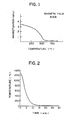
- the present inventors have found that it is an effective means to reduce a load on the combustion-melting zone in the sintering bed without any use of a mechanical means such as stand materials. Accordingly, as a result of further studies based on the foregoing finding, the present inventors have found that load reduction by a magnetic means is most suitable for actual operation. That is, the present inventors conducted detailed tests on the magnetic property of sintered cakes, and found that magnetism is substantially lost at 600°C or higher, but a weak magnetism was found to exist below 600°C in such an order as to allow floating by a commercial magnetizing apparatus, as shown in Fig. 1.
- the surface layer region of the sintering bed had a magnetism when quenched and even if combustion was under way in the combustion-melting zone of the sintering bed. That is, the present inventors conceived from their finding that the sintering reaction could be carried out while floating the sintered cakes, and have established the present invention.
- the present invention is also applicable to a method for sintering other ores than iron ores, based on a downward air suction flow, so long as the sintered cakes have a magnetism.
- the magnetic floating force can be applied in two ways, that is, by applying a magnetic floating force so as to reduce the downward force of sintered cakes within a range of the downward resultant force from the gravitation and a suction pressure, on one hand, and by applying a magnetic floating force layer as large as the downward resultant force from the gravitation and a suction pressure.
- the objects of the present invention can be attained by a method and an apparatus for sintering operation, characterized by igniting a layer of raw materials, thereby continuing sintering, then applying a magnetic field to sintered cakes when the sintered cakes have a predetermined thickness as the sintering proceeds, applying to the sintered cakes a magnetic floating force larger than a resultant force from the load of the sintered cakes and a downward force on the sintered cakes due to the suction pressure of a blower, thereby peeling the sintered cakes from the sintering bed below the sintered cakes, and then continuing the sintering, while applying a magnetic field to the peeled sintered cakes, thereby maintaining the peeled sintered cakes in a floating state, and thereby continuing the sintering.
- Fig. 1 is a diagram showing relations between a magnetization of sintered cakes, when a magnetic field of 10 kOe is applied to the sintered cakes, and a temperature (dependency of magnetic permeability on temperature).
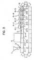
- Fig. 2 is a diagram showing relations between time and cooling temperature at a level of 100 mm from the surface of sintering bed (changes in the surface layer temperature of sintering bed).
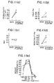
- Fig. 3 is a view showing one embodiment of an apparatus in the case of carrying out the present method for sintering operation by using a DL type sintering machine.
- Fig. 4 is a schematic perspective view of a magnetic floating apparatus according to the present invention, where magnets are provided over a pallet.
- Fig. 5(a) is an enlarged schematic plan view showing one embodiment of the structure of the magnet according to the present invention shown in Fig. 4, and Fig. 5(b) is a cross-sectional view along the line V(b)-V(b) of Fig. 5(a).
- Fig. 6 is a view showing one embodiment of the structure of an entire selectrical system of an apparatus for carrying out the present process for sintering operation.
- Fig. 7 is a schematic perspective view showing a second embodiment of a magnetic floating apparatus according to the present invention, where magnets are provided above and aside a pallet.
- Fig. 8 is a schematic perspective view showing a third embodiment of a magnetic floating apparatus according to the present invention, where a permanent magnet is provided above a pallet.
- Fig. 9(a) is a schematic perspective view showing a fourth embodiment of a magnetic floating apparatus according to the present invention, where a set of catapillar magnets are provided above pallets, and Fig. 9(b) is a cross-sectional view along the line IV(b)-IV(b) of Fig. 9(a).
- Fig. 10(a) is a diagram showing one example of relations between the depth of a sintering bed (thickness of sintered cakes formed with progress of sintering) and the load thereof on the combustion-melting zone in a conventional sintering process without any step for reducing the load of sintered cakes.
- Fig. 10(b) is a diagram showing one example showing relations between the depth of a sintering bed and the load thereof on the combustion-melting zone according to a first mode of the present process for sintering operation, where the load of sintered cakes is reduced at a constant rate.
- Fig. 10(c) is a diagram showing another example showing relations between the depth of a sintering bed and the load thereof on the combustion-melting zone in a second mode of the present process for sintering operation, where the magnetic floating force is increased according to the increment of the load of the sintered cakes, and a constant load of the sintered cakes is given in any situation in the lower layer of the sintering bed.
- Fig. 10(d) is a diagram showing a further example of relations between the depth of a sintering bed and the load thereof on the combustion-melting zone according to a forth mode of the present process, for sintering operation where a certain amount of the load of sintered cakes is reduced by peeling sintered cake and then by maintaining the peeled sintered cakes in a floating state.
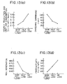
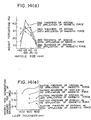
- Figs. 11(a) to 11(e) are diagrams showing sintering results obtained by sintering according to Figs. 10(a) to 10 (d), where marks ⁇ , ⁇ , ⁇ and ⁇ show sintering processes based on Figs. 10(a), 10(b), 10(c) and 10(d), respectively.
- Fig. 12(a) is a diagram showing one example of relations between the depth of a sintering bed and the load thereof on the combustion-melting zone as a resultant force from the load of sintered cakes and the suction pressure of a blower.
- Fig. 12(b) is a diagram showing another example of relations between the depth of a sintering bed and the load thereof on the combustion-melting zone according to a third mode of the present process for sintering operation, where the load of sintered cakes given to the combustion-melting zone in a certain depth of a sintering bed in a pallet is made to zero.
- Fig. 12(c) is a diagram showing other example of relations between the depth of a sintering bed and the load thereof on the combustion-melting zone according to the second mode of the present process for sintering operation, where a half amount of the load of sintered cakes, which are produced in a certain depth of a sintering bed in a pallet without any application of a magnetic floating force, is reduced.
- Figs. 13(a) to 13(b) are diagrams showing sintering results obtained according to Figs. 12(a) to 12(c), where "base (full load)", “half load” and “no load” show sintering processes conducted according to Fig. 12(a), Fig. 12(c) and Fig. 12(b), respectively.
- Figs. 14(a) to 14(e) are diagrams showing sintering results obtained by changing the thickness of sintering bed and the suction presssure by a blower as shown in Table 3, where O shows a case where the suction pressure is 1,000 mm aq. without any application of a magnetic force, ⁇ shows a case where the suction pressure is 1,000 mm aq. with application of a magnetic force, ⁇ shows a case where the suction pressure is 2,000 mm aq. without any application of a magnetic force, and ⁇ shows a case where the suction pressure is 2,000 mm aq. with application of a magnetic force. Moreover, the magnetic force was applied in such a strength that the load given to the combustion-melting zone becomes zero.
- a magnetic floating force can be applied to any part at any location, but cooling proceeds continuously from the surface layer of the formed sintered cakes, and, as shown in Fig. 2, the surface layer region is cooled within a short time after the ignition, and thus a magnetic field is applied to the upper level region of sintered cakes to develop a floating force also in view of the characteristics of sintered cakes, that is, better magnetic characteristics at a lower temperature, as shown in Fig. 1.
- the present invention is not applied to the very former half part of sintered part of strand in the upper level region of sintering bed, where combustion is in progress. But this is not a handicap for the present invention, because the magnetic floating of the upper level region is not originally effective.
- the magnetic floating force can be applied in two ways, that is, by applying a magnetic floating force so as to reduce the downward force of sintered cakes within a range of the downward resultant force from the gravitation and a suction pressure, on one hand, and by applying a magnetic floating force larger than the downward resultant force from the gravitation and a suction pressure.
- FIG. 3 one embodiment of an apparatus for carrying out the present process for sintering operation by using a DL type sintering machine is shown.
- Sintering raw materials stored in a surge hopper 1 for sintering raw materials are charged to pallets of a sintering machine 2 through a raw material charger 3 and then ignited by an ignition furnace 4. Sintering proceeds while the combustion-melting zone is gradually migrated downwards from the surface region toward the lower level region. After passage through the ignition furnace 4, sintering completes from the upper level region of sintering bed with the progress of the strand to form solidified and cooled sintered cakes.
- FIG. 3 the mode of gradual downward migration of the combustion-melting zone (sintering reaction zone) through the layer of raw materials on pallets 2-2 to 2-9 is shown by an alternate long and short dash line 5.
- the sintered zone In the region above the line 5, that is, the sintered zone, there are the so called sintered cakes which have finished the sintering reaction, whereas in the region below the line 5, there are raw materials to be sintered.
- Point 8 is a point of completion of sintering at which the sintered cakes are discharged at the location of pallet 2-10.
- a magnetic field is applied from magnetic floating apparatuses 6-1 to 6-5, provided above the pallets 2-5 to 2-9 by mounting supports 7 while controlling the electric current through magnetic coils and gap sizes between the magnetic pole end and the surface of sintering layer to predetermined ranges, respectively, thereby adjusting the magnetic floating force.
- a load on combustion-melting zone and on the layer of raw materials lower than the combustion-melting zone 5 can be made zero or reduced.
- the air permeability through the combustion-melting zone can be improved, resulting in stabilization of combustion of coke breeze in the raw materials and acceleratation of combustion speed.
- sintering is carried out while applying to sintered cakes in the upper level region, that is, the combustion-completed portion a magnetic floating force of given magnitude within such a range as not to exceed the resultant force from the gravitation of sintered cakes and a downward force on the sintered cakes by a suction pressure of a blower from a location where the sintered cakes come to have a given thickness with progress of sintering after the ignition of the layer of raw materials.
- the force was larger at a lower level.
- the downward force is made lower by a given magnitude than that in the conventional method without any application of the magnetic force.
- a magnetic field is applied to the sintered cakes formed by sintering when the sintered cakes come to have a given thickness with progress of sintering after the ignition of the layer of raw materials, and sintering is continued while applying a magnetic force to the sintered cakes by increasing a magnetic floating force so as to correspond to an increasing load of the sintered cakes due to the increasing thickness of the sintered cakes with progress of sintering.
- the magnetic floating force must be increased as the combustion-melting zone goes to a lower level, thereby to control the downward force on the combustion-melting zone to a constant level. In this case, as compared with the conventional method, the productivity and yield can be improved and the qualities (reducibility and particle size distribution) can be also considerably improved.
- a magnetic force equal to the resultant force from the gravitation of formed sintered cakes and a downward force on the sintered cakes by the suction pressure of a blower is applied to the sintered cakes from a location where the sintered cakes come to have a given thickness with progress of sintering after ignition of the layer of raw materials, and thus sintering is continued in the resulting load-free state. That is, the sintered cakes are maintained under a magnetic floating force equal to the downward froce on the combustion-melting zone.
- the combustion-melting zone expands or shrinks to some extent between the sintered cakes and the layer of raw materials below the sintered cakes, a magnetic floating force substantially equal to the resulting force may be applied.
- the productivity and yield can be improved, and the qualities (reducibility and particle size distribution) can be remarkably improved.
- sintering is carried out while maintaining a gap between the magnetic pole end and the surface of the sintering bed, for example, in a range of 10 to 50 mm, though dependent on compositions of sintering raw materials, and smoothness of sinter bed surface, etc.
- a magnetic floating force is made to act on the sintered cakes by controlling an electric current through electromagnetic coils, for example, to apply a magnetic field of not less than 0.3T (Tesla) to sintered cakes.
- a magnetic force larger than the resultant force from the gravitation of formed sintered cakes and a downward force on the sintered cakes by the suction pressure of a blower is drastically applied to the sintered cakes when the sintered cakes come to have a given thickness with progress of sintering after ignition of the layer of raw materials, thereby peeling sintered cakes off the sintering bed below the sintered cakes.
- Sintering is continued while continuously applying a magnetic force to the peeled sintered cakes to maintain the sintered cakes in a floated state with a constant gap range between the magnetic pole end and the surface of the sintering bed or with zero gap therebetween to attract the sintered cakes to the magnetic pole end.
- the sintered cakes are made to peel off from the sintering bed below the sintered cakes, for example, when the temperature of sintered cakes is brought into a range of room temperature to 500°C, preferably room temperature 413°C in a range of 50 to 150 mm from the surface of sintered cakes with progress of sintering, and/or when the sintered cakes come to have a thickness ranging from 200 to 400 mm.
- a magnetic field is applied to the sintered cakes by controlling an electric current through electromagnetic coils, thereby making a magnetic floating force to act on the sintered cakes, and sintering is continued while keeping the peeled sintered cakes in a floating state and while maintaining a gap between the magnetic pole end and the surface of the sintering bed within, for example, a range of 10 to 50 mm.
- a magnetic field is applied to the sintered cakes by controlling an electric current through electro-magnetic coils, thereby to make a magnetic floating force to act on the sintered cakes as attracted to the magnetic pole end, and sintering is continued while keeping the gap between the magnetic pole end and the surface of the sintering bed zero and while keeping the peeled sintered cakes in a floating state.
- Fig. 4 shows one embodiment of the structure of a magnetic floating apparatus 6-1 according to the present invention, which comprises magnets 11 each comprising a magnetic coil 9 and an iron core frame 10 provided above a pallet 2-5 and supported by a mounting frame 7, a laser-type or ultrasonic type gap sensor 17 for measuring a gap size between a magnetic pole end and the surface of sintering bed formed in the pallet 2-5, and a manually operable, electrically movable level controller 13 capable of adjusting the gap size, where a magnetic floating force can be adjusted by controlling an electric current through the magnetic coil 9 and the mounting position to the pallet 2-5, particularly the gap between the magnetic pole end and the surface of sintered cakes.
- power for the magnetic floating apparatus 6-1 is made within the resultant force from the graviation of formed sintered cakes and a downward force on the sintered cakes by suction pressure of a blower.
- Power for the magnetic floating apparatus 6-1 for conducting peeling of sintered cakes is made larger than that for other magnetic floating apparatuses 6-2 to 6-5. After the peeling of sintered cakes, the magnetic floating force is satisfactory for only maintaining the sintered cakes in a floating state, and thus power for magnetic floating apparatuses 6-2 to 6-5 other than 6-1 can be smaller than that for peeling the sintered cakes
- Numeral 14 are rollers for moving the pallet 2-4.
- an electromagnet is used in the present invention as the magnet
- a compound magnet comprising an electromagnet and a permanent magnet partially integrated in the electromagnet can be also used in the present invention.
- a superconducting magnet can be used to attain a lower cost, a smaller size and a lighter weight.
- a permanent magnet can be also used, if it has a high magnetism.
- cooling system of coil with water is used.
- Fig. 5(a) is an enlarged schematic plan view of a magnet 11 comprising a magnetic coil 9 and an iron core frame 10 in Fig. 4, and Fig. 5(b) is a cross-sectional view along the line V(b)-V(b) of Fig. 5(a).
- the lower end 16 at the center of the iron core frame 10 will be an N pole, and a magnetic field is applied to the sintered cakes from pairs of each of S pole and N pole to make a magnetic floating force to act on the sintered cakes.
- a magnetic field can be applied to both sides and/or the upper side of the sintered cakes.
- Fig. 6 is a view showing one embodiment of an electrical structure of entire system according to the present invention, where at least one apparatus for sintering operation, which comprises a magnetic floating apparatus 6-1 comprising at least one magnet 11 provided above a pallet of a sintering machine by a mounting frame 7 and arranged to direct a magnetic pole end toward the pallet and a magnet level controller 13 for controlling a gap size between the magnetic pole end and the surface of sintering bed formed in the pallet, and a gap sensor 17 for measuring a gap size is prepared, the magnetic floating apparatus 6-1 and the gap sensor 17 being provided in the longitudinal direction of the sintering machine in a magnetizing region extending from the outlet of an ignition furnace to the inlet to a sintered ore discharge section.
- a magnetic floating apparatus 6-1 comprising at least one magnet 11 provided above a pallet of a sintering machine by a mounting frame 7 and arranged to direct a magnetic pole end toward the pallet and a magnet level controller 13 for controlling a gap size between the magnetic pole end and the surface of
- a necessary magnetic floating force for the position of at least one magnet 11 in the longitudinal direction of the sintering machine is input to a controller 18 as data to enable selection of individual magnetization patterns.
- the controller 18 computes an electric current from a set electromagnetic force and the gap to control an electric current to the magnet 11 through a main power source 20, thereby controlling the set electromagnetic force and also control the gap size by the magnet level controller 13, thereby controlling the magnetic floating force.
- the magnet level controller 13 can be manually operated through an operating board 21 to control the gap size.
- Control of the magnetic floating force by the controller 18 is to control the electric current at a constant gap size in principle.
- the floating force is decreased with increasing gap size due to the sintering shrinkage and thus there is a fear of failure to apply a necessary floating force for the magnetization of the lower level region.
- the gap size must be maintained constant, for example, in a range of 10 to 50 mm, preferably 20 to 30 mm by manual level control of the magnet.
- An electromagnet and/or a permanent magnet is used as the magnet 11 to apply a magnetic field to the sintered cakes. Only the electromagnetic coil may be used, but electric power can be saved by combined use of the permanet magnet.
- Fig. 7 shows another embodiment of the structure of a magnetic floating apparatus according to the present invention, which is directed to practice the foregoing first to fourth modes of the present invention, where a magnet 11 comprising a magnetic coil 9 and an iron core frame 10 is provided above a pallet 2-1 of a sintering machine by a mounting frame 7.
- a permanent magnet 11 can be provided above a pallet 2-1 of a sintering machine by a mounting frame 7, as shown in Fig. 8 as a magnetic floating apparatus 6, whereby the same effect as above can be obtained to some extent.
- FIGs. 9(a) and 9(b) show other embodiment of a magnetic floating type apparatus for sintering operation according to the present invention, which is directed to practice the foregoing fourth mode of the present invention, where an magnetic floating type apparatus for sintering operation, which comprises a rotatable catapillar belt comprising a plurality of magnets 11 each having magnet pole ends, provided above a set of pallets of a sintering machine and arranged outwards from the catapillar belt and which is provided in the longitudinal direction of the sintering machine in a magnetizing region extending from the outlet of an ignition furnace to the inlet to a 'sintered ore discharge section, is used.
- an magnetic floating type apparatus for sintering operation which comprises a rotatable catapillar belt comprising a plurality of magnets 11 each having magnet pole ends, provided above a set of pallets of a sintering machine and arranged outwards from the catapillar belt and which is provided in the longitudinal direction of the sintering machine in
- a method for controlling a magnetic floating apparatus 6 shown in Figs. 9(a) and 9(b) will be explained, referring to Fig. 6. That is, a magnetic floating apparatus 6 shown in Figs. 9(a) and 9(b) is used, and a necessary magnetic floating force for the position of at least one magnet 11 in the longitudinal direction of the sintering machine is input to a controller 18 as data to enable selection of individual magnetization patterns.
- the controller 18 computes an electric current from a set electromagnetic force to control an electric current to the magnet 11 through a main power source 20, thereby controlling the magnetic floating force.
- the magnets 11 reach the sintered ore discharge section, that is, sintered cake discharge section, and when the magnets 11 as transferred so far as the underlayer 22-1 of the catapillar belt are changed to an upper 22-2 of the catapillar belt by rotation, the passage of the electric current to the electromagnetic coils of the magnets is discontinued, thereby making the magnets to proceed as the upper layer 22-2 without any application of a magnetic field. In this manner, the magnetic floating force is controlled.
- a magnetic floating type apparatus for sintering operation shown in Figs. 3 to 6, was used.
- Electric power consumption / electromagnet was 70 kWwith a coil turning of 250, an electric current of 350 A and a voltage of 200 V.
- the magnetizing region extending from the outlet of an ignition furnace 4 to the inlet 8 of sintered ore discharge section was 35 m long and the gap sensor 17 was of ultrasonic type.
- a manually operable, electrically movable magnet level controller was used as 13.
- a necessary magnetic floating force for the position of at least one magnet 11 in the longitudinal direction of the sintering machine was input to the controller 18 to enable selection of the following magnetization pattern.
- the controller 18 computed an electric current from a set electromagnetic force and the gap to control an electric current to the magnet 11 through the main power source 20, thereby controlling the set electromagnetic force and also control the gap size by the magnet level controller 13, thereby controlling the magnetic floating force.
- sintering was carried out while reducing the load of sintered cakes on the combustion-melting zone 5.
- An electric current of 120 A was passed to the individual magnetic floating apparatuses while controlling the gap between the magnetic pole ends and tile surface of the sintered cakes to 30 mm, and a magnetic floating force corresponding to one half of total (700 kg/m 2 ) of the suction pressure on the combusion-melting zone 5 by a blower and the load of formed sintered cakes was applied to the sintered cakes formed with progress of sintering in the region extending from the point, about 15 m far from the outlet of the ignition furnace 4 to BTP to reduce the load of sintered cakes on the combustion-melting zone 5. Sintering was carried out in this manner.
- the thickness of the sintering bed from the ignition furnace 4 is decreased by shrinkage with progress of sintering and the sintering bed is shrunk by about 100 mm at a point near the sintered ore discharge section, whereas the shrinkage of this example 1 was about 45 mm.
- Magnetic floating type apparatus for sintering operation as in Example 1 was used.
- magnetic floating apparatus 6-1 to 6-5 as shown in Fig. 4 were provided at a distance of 1 m in a region extending from a point, about 15 m far from the ignition furnace 4 (temperature at a level of 240 mm from the surface of sintered cakes: 600°C, thickness of sintered cakes: 200 mm) to BTP, about 50 m far from the ignition furnace 4, as shown in Fig. 3.
- sintering was carried out while reducing the load of sintered cakes on the combustion-melting zone 5 in the region extending from the point, about 15 m far from the ignition furnace 4 to BTP with progress of sintering.
- an electric current was passed to the individual magnetic floating apparatuses while controlliny the gap between the magnetic pole ends and the surface of sintered cakes to 30 mm, and increasing continuously the electric current to the individual magnetic floating apparatuses from zero A at the position with a sintered cake layer thickness of 200 mm to 150 A at the position with a sintered cake layer thickness of 600 mm, thereby applying to the sintered cakes a magnetic force corresponding to an increase in the load of increasing sintered cakes resulting from the increasing sinter cake layer thickness in the region extending from the point, about 15 m far from the ignition furnace to BTP with progress of sintering.
- the thickness of the sintering bed from the ignition furnace 4 is decreased by shrinkage with progress of sintering and the sintering bed is shrunk by about 100 mm at a point near the sintered ore discharge section, whereas the shrinkage of this example was about 48 mm.
- Magnetic floating type apparatus for sintering operation as in Example 1 was used.
- magnetic floating apparatuses 6-1 to 6-5 as shown in Fig. 4 were provided at a distance of 1 m in a region extending from a point, about 15 m far from the ignition furnace 4 (temperature at a level of 240 mm from the surface of sintered cakes: 600°C; thickness of sintered cakes: 200 mm)to BTP, about 50 m far from the ignition furnace 4, as shown in Fig. 3.
- Fig. 10(d) sintering was carried out while reducing the load of sintered cakes on the combustion-melting zone.
- sintering was carried out without passing an electric current to the magnetic floating apparatuses 6-1 to 6-2 in the region from the sintered cake layer thickness of zero mm to that of 200 mm, and then an electric current of 300 A was passed to the magnetic floating apparatuses 6-1 to 6-2 in the region from the sintered cake layer thickness of 200 mm, that is, the region of about 20 m far from the ignition furnace 4, thereby applying to the sintered cakes a larger magnetic force (700 kg/m 2 ) than the resultant force(i.e. a magnetic force as a total of the blower suction pressure and the load of the sintered cakes) to peel the sintered cakes off the sintering bed below the sintered cakes.
- a larger magnetic force 700 kg/m 2
- the resultant force i.e. a magnetic force as a total of the blower suction pressure and the load of the sintered cakes
- an electric current of 100A was passed to the individual magnetic floating apparatuses 6-3 to 6-5 while controlling the gap between the magnetic pole ends and the surface of sintered cakes to 20 mm in the region from the sintered cake layer thickness of 400 mm to that of 600 mm, i.e. the region at the point of peeling of the sintered cakes to BTP, thereby applying to the peeled sintered cakes a magnetic force (700 kg/m 2 ) corresponding to the resultant force from the blower suction pressure and the load of the peeled sintered cakes.
- sintering was carried out while maintaining the peeled sintered cakes in a floating state.
- the thickness of the sintering bed from the ignition, furnace 4 is decreased by shri.nkage with progress of sintering and the sintering bed is shrunk by about 100 mm at a point near the sintered ore discharge section, whereas shrinkage of this example was about 20mm.
- sintering was carried out without passing an electric current to the magnetic floating apparatus 6-1 to 6-2 in the region from the sintered cake layer thickness of 0 mm to that of 180 mm, and then an electric current of 160 to 330 A was passed to the individual magnetic floating apparatuses 6-3 to 6-5 while controlling the gap between the magnetic pole ends and the surface of sintered cakes to 30 mm in the region from the sintered cake layer thickness of 180 mm to that of 600 mm, that is, the region from a point, about 20 m far from the ignition furnace 4 to BTP, thereby preventing peeling of the sintered cakes from the combustion-melting zone and the layer of raw materials.
- the thickness of the sintering bed from the ignition furnace 4 is decreased by shrinkage with progress of sintering and the sintering bed is shrunk by about 100 mm at a point near the sintered ore discharge section. It was found that the shrinkage of this example was about 35 mm.
- base full load
- half load means a case where the resultant force on the combustion-melting zone was reduced to about one half by application of a magnetic force, as shown in Fig. 12(c); and "no load” means a case where sintering was carried out while making the resultant force on the combustion-melting zone 5 zero in this Example.
- the productivity was increased by approximately 30% in the case with application of the magnetic force, as compared with the case without any application of the magnetic force. This seems to be the largest effect of this Example.
- the yield was on the same level as in the case without any application of the magnetic force, but usually an increase in the productivity lowers the yield and thus the yield is substantially improved by the corresponding increase in the productivity.
- the reducibility was improved by 8%, and a sharp particle size distribution was obtained and uniform particle sizes were obtained. Thus, the qualities were considerably improved.
- the sintering time was shortened from 47 minutes to 34 minutes, and the hourly production per unit air consumption was increased from 2.74 (t/h/m 2 )/Nm 3 to 3.58 (t/h/m 2 )/Nm 3 , while the sintering shrinkage was decreased from 115 mm to 35 mm and total NOx generation was reduced by 30%. Further, although the coke combustion speed was about 2 times increased, any change was not caused in the combustion effect. Hourly generation of NOx was very low. In addition, SOx generation was in an increasing tendency, but was more concentrated toward the sintered ore discharge section.
- magnetic floating apparatuses 6-1 to 6-5 shown in Fig. 7 were provided at a distance of 1.5 m in a region extending from a point, about 20 m far from the ignition furnace 4 to BTP 8, about 100 m far from the ignition furnace 4, as shown in Fig. 3, and an electric current was passed to the individual magnetic floating apparatuses to float sintered cakes.
- the thickness of the sintering bed from the ignition furnace 4 is decreased by shrinkage with progress of sintering and the sintering bed is shrunk by about 150 mm at a point near the sintered ore discharge section.
- the shrinkage of this Example was found to be about one half.
- the productivity was improved from 35 t/d/m 2 to 42 t/d/m 2 .
- magnetic floating apparatuses 6-1 to 6-5 shown in Fig. 7 were provided at a distance of 1.5 m in the strand direction in a region from a point, 2 m far from the ignition furnace 4 to BTP 8, 50 m far from the ignition furnace 4 to conduct sintering operation while floating the sintered cakes.
- a catapillar type, magnetic floating apparatus for sintering operation as shown in Figs. 9(a) and 9(b) was used.
- a set of magnets were rotatably and movably provided in the longitudinal direction of the sintering machine in a region extending from a point, about 20 m far from the ignition furnace 4 (temperature at a level of 240 mm from the surface of sintered cake: 600°C; thickness of sintered cakes: 220 mm) to BTP, about 50 m far from the ignition furnace 4, so that the set of magnets constituting the underlayer 22-1 of a catapillar may be counter-posed to a set of pallets.
- sintering was carried out in a mode shown in Fig. 10(d) while reducing the weight of sintered cakes on the combustion-melting zone 5. That is, sintering was carried out without passing an electric current to the magnets in the region from the sintered cake layer thickness of 0 mm to that of 220 mm, and an electric current of 300 A was passed to the magnets in the region from the sintered cake layer thickness of 220 mm, that is, the region from a point, about 20 m far from the ignition furnace 4, thereby applying to the sintered cakes a larger magnetic force (700 kg/m 2 ) than the resultant force from the blower suction pressure on the combustion-melting zone 5 and the load of formed sintered cakes, to peel the sintered cakes from the sintering bed below the sintered cakes.
- a larger magnetic force 700 kg/m 2
- the magnetic field was applied to the peeled sintered cakes and then the magnetic field-applied magnets proceeded in the direction of the strand while holding the peeled sintered cakes as attracted to the magnets.
- an electric current of 30 A was passed to the magnets in a region from the sintered cake layer thickness of 220 mm to that of 600 mm, i.e. the region from the point of peeling completion to BTP, to make the gap between the magnetic pole ends and the surface of the sintered cakes zero, thereby carrying out sintering while maintaining the peeled sintered cakes in a floating state as attracted to the magnets.
- the productivity was improved by 12% in the case with application of the magnetic force, as compared with the case without any application of the magnetic force, but the yield was found to be in the same level as in the case without any application of the magnetic force.
- Usually an increase in the productivity lowers the yield, and thus the yield is substantially improved by the corresponding increase in the productivity.
- the reducibility was improved by 6%, and a good particle size distribution and unform particle sizes were obtained. Thus, the qualities were considerably improved.
- magnetic floating apparatuses 6-1 to 6-5 shown in Fig. 4 were provided at a distance of 1.5 m in a region extending from a point, about 20 m far from the ignition furnace 4 to BTP 8, about 110 m far from the ignition furnace 4, as shown in Fig.
- Example 3 The same magnetic floating type apparatus for sintering operation as in Example 1 was used.
- the sintering bed thickness and the blower suction pressure were changed as shown in Table 3 to conduct sintering with no load in the DL sintering machine in the same manner as in Example 4, thereby examining the novel process for sintering operation according to the present invention.
- Table 3 Sintering bed thickness (mm) 400 600 800 Suction pressure (mm aq.) 1,000 magnet force applied - ⁇ ⁇ no magnet force ⁇ ⁇ - 2,000 magnet force applied - ⁇ ⁇ no magnet force - ⁇ -
- Results are shown in Figs. 14(a) to 14(e), where ⁇ shows a case without any application of a magnetic force at a suction pressure of 1,000 mm aq., ⁇ shows a case With an application of a magnetic force at a suction pressure of 1,000 mm aq.; ⁇ shows a case without any application of a magnetic force at a suction pressure of 2,000 mm aq.; and ⁇ shows a case with application of a magnetic force at a suction pressure of 2,000 mm aq.
- sintering operation can be carried out at a suction pressure of 1,000 mm aq. when magnetic floating is applied to a large scale, sintering machine operable at a suction pressure of 2,000 mm aq.
- a main blower provided with VVVF (Variable Voltage Variable Frequency) requires 20 kW/ton-sinter usually, and thus 8 kW/tons sinter can be reduced by using the present invention.
- 3 kW/ton-sinter is required for the magnetic floating apparatuses.
- sintering bed thickness can increase the yield, but the bed thickness can be increased only to the order of 600 mm owing to the permeability as a bottleneck.
- sintering can be carried out in a higher sintering bed thickness than 700 mm, which has been difficult in the conventional method.
- the yield can be also improved by maximum 5%.
Landscapes
- Engineering & Computer Science (AREA)
- Mechanical Engineering (AREA)
- Chemical & Material Sciences (AREA)
- General Engineering & Computer Science (AREA)
- Life Sciences & Earth Sciences (AREA)
- General Life Sciences & Earth Sciences (AREA)
- Geochemistry & Mineralogy (AREA)
- Geology (AREA)
- Manufacturing & Machinery (AREA)
- Environmental & Geological Engineering (AREA)
- Materials Engineering (AREA)
- Metallurgy (AREA)
- Organic Chemistry (AREA)
- Manufacture And Refinement Of Metals (AREA)
Description
- This invention relates to a method and an apparatus for producing sintered iron ores by a sintering machine of downward air suction flow type such as a DL (Dwight-Lloyd) type sintering machine, a GW (Greenawalt) type sintering machine, etc.
- In a DL sintering process, sintering reaction proceeds while drawing air downward through the sintering bed and combusting coke breeze contained in the raw materials in the sintering bed, thereby moving a combustion-melting zone having a thickness of a few mn to a few tens mm in the thickness direction of the raw materials in the sintering bed in the pallet downwards, as disclosed in Tekko Binran (Iron & Steel Handbook) II, Seisen Seiko (Pig Iron & Steel Making), third edition, page 106 et seq., compiled by Nihon Tekko Kyokai (Association of Iron and Steel of Japan) and published on October 15, 1979.
- In the DL sintering process, sintering proceeds in the combustion-melting zone of the sintering bed with the air preheated through the already sintered cakes in the upper level region, and thus the raw materials are liable to undergo sintering in a heat excess state in the combustion-melting zone, whereas the raw materials are liable to undergo sintering in a heat deficient state in the upper level region. Thus, an amount of liquid meltings is increased in the combustion-melting zone in accordance with a heat gradient in the thickness of the layer of raw materials.
- In addition, the sintered cakes in the upper level region give a pressing load to the combustion-melting zone by applying a load from the gravitation of the formed sinter cakes and a downward force on the sinter cakes by the suction of a blower. That is, the liquid meltings under the load are highly liable to clog the pores in the sintering bed, and the necessary permeability conditions for stable combustion of the coke breeze contained in the layer of raw materials are deteriorated in the combustion-melting zone of the sintering bed, resulting in a decrease in the sintering speed. Simultaneously, a lower yield and an increasing NOx results by the deterioration of coke breeze combustion. Besides, qualitatively the strength of sintered ores is lowered and the number of pores is reduced, resulting in poor reducibility.
- To solve these problems, it was proposed to improve the permeability by decreasing the layer thickness to reduce the permeability resistance or by using an increased amount of quick lime to intensify granulation of raw materials. However, the former means lower the yield and strength and the latter means require expensive quick lime.
- Japanese Patent Application Kokai (Laid-open) No. 2-254125 discloses an effective method for preventing the decrease in yield and quality at a low cost by supporting sintered cakes with use of stand materials. However, the proposed method still has such problems as necessity for periodic replacement of stand materials used for the supporting due to abrasion of the stand materials.
- The reference Transactions ISIJ, vol. 24, 1984, page B-35 discloses a method for detecting a state of a sintering reaction by measuring a change of the magnetic permeability by analysing the FeO content in the sintered cakes. The sintering operation is controlled by other means.
- An object of the present invention is to provide a method and an apparatus for sintering operation in which the load on the combustion-melting zone in the sintering bed is reduced and which is capable of stable production of sintered ores of good quality by securing a high productivity and in a high yield, while solving the problems of the prior art.
- This object is solved with the features of the claims. According to the invention a method and an apparatus for sintering operation capable of weight-reduced operation in a non-contact state by magnetically floating sintered cakes are provided.
- As a result, first, the productivity is greatly elevated and the quality can be improved and power consumption can be reduced due to reduction in air suction pressure when applied to a sintering machine with the blower drived by variable voltage and variable frequency motor.
- On the other hand, when the elevation of the productivity is not needed, the sintering bed thickness can be ccnsisterably increased by virtue of improved permeability so that the present invention can attain a considerable energy saving by increasing yield with increasing bed thickness.
- Second, sintered cakes of the surface layer of the sintering bed are peeled and floated from the sintering bed by magnetic means, and thereby sintering is carried out in the combustion-melting zone of the sintering bed with air preheated through sintered cakes. And thereby the sintering is continued in a load-reduced state, and a thoroughly heat-effective state and well permeability is maintained to advance the reaction efficiently at an accelerated sintering rate without lowering the yield and strength and to enable production of sintered ores with a good reducibility.
- Further, NOx generation can be reduced by virtue of improved permeability and stabilized combustion of coke breeze.
- In addition, when this invented technology is used, conventional quick lime addition, so far used when it is hard to ensure the production of desired level due to deterioration in the permeability through the layer of raw materials in the sintering bed, can be unnecessitated.
- As a result of extensive studies based on experiments to solve the problems of the prior art as mentioned above, the present inventors have found that it is an effective means to reduce a load on the combustion-melting zone in the sintering bed without any use of a mechanical means such as stand materials. Accordingly, as a result of further studies based on the foregoing finding, the present inventors have found that load reduction by a magnetic means is most suitable for actual operation. That is, the present inventors conducted detailed tests on the magnetic property of sintered cakes, and found that magnetism is substantially lost at 600°C or higher, but a weak magnetism was found to exist below 600°C in such an order as to allow floating by a commercial magnetizing apparatus, as shown in Fig. 1. It was also found that the surface layer region of the sintering bed had a magnetism when quenched and even if combustion was under way in the combustion-melting zone of the sintering bed. That is, the present inventors conceived from their finding that the sintering reaction could be carried out while floating the sintered cakes, and have established the present invention.
- The present invention is also applicable to a method for sintering other ores than iron ores, based on a downward air suction flow, so long as the sintered cakes have a magnetism.
- These objects of the present invention can be attained by a method and an apparatus for sintering operation based on a downward air suction flow, characterized by igniting a layer of raw materials, applying a magnetic field to sintered cakes after sintering starts in the upper level region of raw materials, and continuing the sintering while applying a magnetic floating force to the sintering completed upper level region.
- The magnetic floating force can be applied in two ways, that is, by applying a magnetic floating force so as to reduce the downward force of sintered cakes within a range of the downward resultant force from the gravitation and a suction pressure, on one hand, and by applying a magnetic floating force layer as large as the downward resultant force from the gravitation and a suction pressure.
- Furthermore, the objects of the present invention can be attained by a method and an apparatus for sintering operation, characterized by igniting a layer of raw materials, thereby continuing sintering, then applying a magnetic field to sintered cakes when the sintered cakes have a predetermined thickness as the sintering proceeds, applying to the sintered cakes a magnetic floating force larger than a resultant force from the load of the sintered cakes and a downward force on the sintered cakes due to the suction pressure of a blower, thereby peeling the sintered cakes from the sintering bed below the sintered cakes, and then continuing the sintering, while applying a magnetic field to the peeled sintered cakes, thereby maintaining the peeled sintered cakes in a floating state, and thereby continuing the sintering.
- A method and an apparatus for sintering operation according to the present invention will be explained in detail below, in connection with the drawings.
- Fig. 1 is a diagram showing relations between a magnetization of sintered cakes, when a magnetic field of 10 kOe is applied to the sintered cakes, and a temperature (dependency of magnetic permeability on temperature).
- Fig. 2 is a diagram showing relations between time and cooling temperature at a level of 100 mm from the surface of sintering bed (changes in the surface layer temperature of sintering bed).
- Fig. 3 is a view showing one embodiment of an apparatus in the case of carrying out the present method for sintering operation by using a DL type sintering machine.
- Fig. 4 is a schematic perspective view of a magnetic floating apparatus according to the present invention, where magnets are provided over a pallet.
- Fig. 5(a) is an enlarged schematic plan view showing one embodiment of the structure of the magnet according to the present invention shown in Fig. 4, and Fig. 5(b) is a cross-sectional view along the line V(b)-V(b) of Fig. 5(a).
- Fig. 6 is a view showing one embodiment of the structure of an entire selectrical system of an apparatus for carrying out the present process for sintering operation.
- Fig. 7 is a schematic perspective view showing a second embodiment of a magnetic floating apparatus according to the present invention, where magnets are provided above and aside a pallet.
- Fig. 8 is a schematic perspective view showing a third embodiment of a magnetic floating apparatus according to the present invention, where a permanent magnet is provided above a pallet.
- Fig. 9(a) is a schematic perspective view showing a fourth embodiment of a magnetic floating apparatus according to the present invention, where a set of catapillar magnets are provided above pallets, and Fig. 9(b) is a cross-sectional view along the line IV(b)-IV(b) of Fig. 9(a).
- Fig. 10(a) is a diagram showing one example of relations between the depth of a sintering bed (thickness of sintered cakes formed with progress of sintering) and the load thereof on the combustion-melting zone in a conventional sintering process without any step for reducing the load of sintered cakes.
- Fig. 10(b) is a diagram showing one example showing relations between the depth of a sintering bed and the load thereof on the combustion-melting zone according to a first mode of the present process for sintering operation, where the load of sintered cakes is reduced at a constant rate.
- Fig. 10(c) is a diagram showing another example showing relations between the depth of a sintering bed and the load thereof on the combustion-melting zone in a second mode of the present process for sintering operation, where the magnetic floating force is increased according to the increment of the load of the sintered cakes, and a constant load of the sintered cakes is given in any situation in the lower layer of the sintering bed.
- Fig. 10(d) is a diagram showing a further example of relations between the depth of a sintering bed and the load thereof on the combustion-melting zone according to a forth mode of the present process, for sintering operation where a certain amount of the load of sintered cakes is reduced by peeling sintered cake and then by maintaining the peeled sintered cakes in a floating state.
- Figs. 11(a) to 11(e) are diagrams showing sintering results obtained by sintering according to Figs. 10(a) to 10 (d), where marks ●, □, △ and ○ show sintering processes based on Figs. 10(a), 10(b), 10(c) and 10(d), respectively.
- Fig. 12(a) is a diagram showing one example of relations between the depth of a sintering bed and the load thereof on the combustion-melting zone as a resultant force from the load of sintered cakes and the suction pressure of a blower.
- Fig. 12(b) is a diagram showing another example of relations between the depth of a sintering bed and the load thereof on the combustion-melting zone according to a third mode of the present process for sintering operation, where the load of sintered cakes given to the combustion-melting zone in a certain depth of a sintering bed in a pallet is made to zero.
- Fig. 12(c) is a diagram showing other example of relations between the depth of a sintering bed and the load thereof on the combustion-melting zone according to the second mode of the present process for sintering operation, where a half amount of the load of sintered cakes, which are produced in a certain depth of a sintering bed in a pallet without any application of a magnetic floating force, is reduced.
- Figs. 13(a) to 13(b) are diagrams showing sintering results obtained according to Figs. 12(a) to 12(c), where "base (full load)", "half load" and "no load" show sintering processes conducted according to Fig. 12(a), Fig. 12(c) and Fig. 12(b), respectively.
- Figs. 14(a) to 14(e) are diagrams showing sintering results obtained by changing the thickness of sintering bed and the suction presssure by a blower as shown in Table 3, where O shows a case where the suction pressure is 1,000 mm aq. without any application of a magnetic force, ● shows a case where the suction pressure is 1,000 mm aq. with application of a magnetic force, □ shows a case where the suction pressure is 2,000 mm aq. without any application of a magnetic force, and ■ shows a case where the suction pressure is 2,000 mm aq. with application of a magnetic force. Moreover, the magnetic force was applied in such a strength that the load given to the combustion-melting zone becomes zero.
- A method and an appratus for sintering operation according to the present invention will be explained in detail below.
- At first, the zonal structure of sintering reaction in a sintering machine will be explained. In the sintering bed, sintering reaction proceeds downward gradually while pallets move in the advancing direction of strand. Reaction-completed portion of the raw materials is called "sintered cakes" and is entirely in a state of one rock bed in the sintering machine. Right below the sintered cakes there is a combustion-melting zone, where cokes are combusted and ores are partially molten by the heat of combustion and powdery ores are joined together by the partial melting to form sintered cakes. At that time, sintered cakes are formed while the combustion-melting zone keeps joining with the solidification-completed portion (sintered cakes) in the upper level region.
- Below the combustion-melting zone there is a layer of raw materials, whose cokes are combusted down to the bottom by the heat transferred from the combustion-melting zone above the layer of raw materials to promote formation of sintered cakes, and the sintering reaction is thus completed when the layer of raw material becomes a layer of sintered cakes.
- Since the sintered cakes are positioned above the combustion-melting layer, a magnetic floating force can be applied to any part at any location, but cooling proceeds continuously from the surface layer of the formed sintered cakes, and, as shown in Fig. 2, the surface layer region is cooled within a short time after the ignition, and thus a magnetic field is applied to the upper level region of sintered cakes to develop a floating force also in view of the characteristics of sintered cakes, that is, better magnetic characteristics at a lower temperature, as shown in Fig. 1. Thus, the present invention is not applied to the very former half part of sintered part of strand in the upper level region of sintering bed, where combustion is in progress. But this is not a handicap for the present invention, because the magnetic floating of the upper level region is not originally effective.
- The magnetic floating force can be applied in two ways, that is, by applying a magnetic floating force so as to reduce the downward force of sintered cakes within a range of the downward resultant force from the gravitation and a suction pressure, on one hand, and by applying a magnetic floating force larger than the downward resultant force from the gravitation and a suction pressure.
- In the former way, sintered cakes take a state of one rock bed as it is without any peeling, whereas in the latter way sintered cakes are peeled from the combustion-melting zone at the moment when a floating force larger than the downward force is applied, so that sintering proceeds in such a manner that two separate pieces of sintered cakes are formed.
- The present invention will be explained below, referring to the accompanying drawings.
- In Fig. 3, one embodiment of an apparatus for carrying out the present process for sintering operation by using a DL type sintering machine is shown.
- Sintering raw materials stored in a
surge hopper 1 for sintering raw materials are charged to pallets of asintering machine 2 through araw material charger 3 and then ignited by anignition furnace 4. Sintering proceeds while the combustion-melting zone is gradually migrated downwards from the surface region toward the lower level region. After passage through theignition furnace 4, sintering completes from the upper level region of sintering bed with the progress of the strand to form solidified and cooled sintered cakes. - In Fig. 3, the mode of gradual downward migration of the combustion-melting zone (sintering reaction zone) through the layer of raw materials on pallets 2-2 to 2-9 is shown by an alternate long and
short dash line 5. In the region above theline 5, that is, the sintered zone, there are the so called sintered cakes which have finished the sintering reaction, whereas in the region below theline 5, there are raw materials to be sintered.Point 8 is a point of completion of sintering at which the sintered cakes are discharged at the location of pallet 2-10. - When the temperature of sintered cakes is brought to 600°C or lower, preferably a range of room temperature to 500°C, more preferably a range of room temperature to 345°C in a range of 50 to 150 mm from the surface layer of sintered cakes, a magnetic field is applied from magnetic floating apparatuses 6-1 to 6-5, provided above the pallets 2-5 to 2-9 by mounting
supports 7 while controlling the electric current through magnetic coils and gap sizes between the magnetic pole end and the surface of sintering layer to predetermined ranges, respectively, thereby adjusting the magnetic floating force. - Thus, by making a magnetic floating force act on the sintered cakes, a load on combustion-melting zone and on the layer of raw materials lower than the combustion-
melting zone 5 can be made zero or reduced. And by making the load on the layer of raw materials zero or reducing the load, the air permeability through the combustion-melting zone can be improved, resulting in stabilization of combustion of coke breeze in the raw materials and acceleratation of combustion speed. - The modes of applying a magnetic force in the present invention will be explained below.
- According to the first mode of the present invention, as shown in Fig. 10(b), sintering is carried out while applying to sintered cakes in the upper level region, that is, the combustion-completed portion a magnetic floating force of given magnitude within such a range as not to exceed the resultant force from the gravitation of sintered cakes and a downward force on the sintered cakes by a suction pressure of a blower from a location where the sintered cakes come to have a given thickness with progress of sintering after the ignition of the layer of raw materials. Conventionally the force was larger at a lower level. The downward force is made lower by a given magnitude than that in the conventional method without any application of the magnetic force.
- Even if the magnitude of the magnetic floating force is small, if it is applied, it is effective. In this case, as compared with the conventional method, the productivity and yield can be improved, and qualities (reducibility and particle size distribution) can be improved to some extent.
- According to the second mode of the present invention, as shown in Fig. 10(c) or Fig. 12(c), a magnetic field is applied to the sintered cakes formed by sintering when the sintered cakes come to have a given thickness with progress of sintering after the ignition of the layer of raw materials, and sintering is continued while applying a magnetic force to the sintered cakes by increasing a magnetic floating force so as to correspond to an increasing load of the sintered cakes due to the increasing thickness of the sintered cakes with progress of sintering. The magnetic floating force must be increased as the combustion-melting zone goes to a lower level, thereby to control the downward force on the combustion-melting zone to a constant level. In this case, as compared with the conventional method, the productivity and yield can be improved and the qualities (reducibility and particle size distribution) can be also considerably improved.
- According to the third mode of the present invention, as shown in Fig. 12(b), a magnetic force equal to the resultant force from the gravitation of formed sintered cakes and a downward force on the sintered cakes by the suction pressure of a blower is applied to the sintered cakes from a location where the sintered cakes come to have a given thickness with progress of sintering after ignition of the layer of raw materials, and thus sintering is continued in the resulting load-free state. That is, the sintered cakes are maintained under a magnetic floating force equal to the downward froce on the combustion-melting zone. Since the combustion-melting zone expands or shrinks to some extent between the sintered cakes and the layer of raw materials below the sintered cakes, a magnetic floating force substantially equal to the resulting force may be applied. In this case, as compared with the conventional method, the productivity and yield can be improved, and the qualities (reducibility and particle size distribution) can be remarkably improved.
- In the foregoing first to third modes of the present invention, sintering is carried out while maintaining a gap between the magnetic pole end and the surface of the sintering bed, for example, in a range of 10 to 50 mm, though dependent on compositions of sintering raw materials, and smoothness of sinter bed surface, etc. Furthermore, a magnetic floating force is made to act on the sintered cakes by controlling an electric current through electromagnetic coils, for example, to apply a magnetic field of not less than 0.3T (Tesla) to sintered cakes.
- According to the fourth mode of the present invention, a magnetic force larger than the resultant force from the gravitation of formed sintered cakes and a downward force on the sintered cakes by the suction pressure of a blower is drastically applied to the sintered cakes when the sintered cakes come to have a given thickness with progress of sintering after ignition of the layer of raw materials, thereby peeling sintered cakes off the sintering bed below the sintered cakes. Sintering is continued while continuously applying a magnetic force to the peeled sintered cakes to maintain the sintered cakes in a floated state with a constant gap range between the magnetic pole end and the surface of the sintering bed or with zero gap therebetween to attract the sintered cakes to the magnetic pole end. In this case, a floating force larger than the downward force on the combustion-melting zone is applied and then the sintered cakes are maintained in a floating state. Thus as compared with the conventional method, the productivity and yield can be improved, and the qualities (reducibility and particle size distribution) can be considerably improved.
- In the foregoing fourth mode, the sintered cakes are made to peel off from the sintering bed below the sintered cakes, for example, when the temperature of sintered cakes is brought into a range of room temperature to 500°C, preferably room temperature 413°C in a range of 50 to 150 mm from the surface of sintered cakes with progress of sintering, and/or when the sintered cakes come to have a thickness ranging from 200 to 400 mm. After the peeling of sintered cakes from the sintering bed below the sintered cakes, a magnetic field is applied to the sintered cakes by controlling an electric current through electromagnetic coils, thereby making a magnetic floating force to act on the sintered cakes, and sintering is continued while keeping the peeled sintered cakes in a floating state and while maintaining a gap between the magnetic pole end and the surface of the sintering bed within, for example, a range of 10 to 50 mm. Or, a magnetic field is applied to the sintered cakes by controlling an electric current through electro-magnetic coils, thereby to make a magnetic floating force to act on the sintered cakes as attracted to the magnetic pole end, and sintering is continued while keeping the gap between the magnetic pole end and the surface of the sintering bed zero and while keeping the peeled sintered cakes in a floating state.
- in the conventional method, permeability is not good in the lower level region in the combustion-melting zone, resulting in excess melting and clogging pores easily and thereby resulting in uneven sintering (due to uneven combustion of cakes). This leads to a lower yield and fluctuation in the qualities. However, in the present invention, good permeability can be maintained throughout the sintering bed and even in the combustion-melting zone, and thus coke breeze can be combusted in a thermally efficient state. That is, efficient reaction can proceed at a higher sintering speed. Thus, the yield can be improved and qualities of sintered ores can be stabilized in a higher level. At the same time a problem of low reducibility due to pore clogging can be also improved.
- Fig. 4 shows one embodiment of the structure of a magnetic floating apparatus 6-1 according to the present invention, which comprises
magnets 11 each comprising a magnetic coil 9 and aniron core frame 10 provided above a pallet 2-5 and supported by a mountingframe 7, a laser-type or ultrasonictype gap sensor 17 for measuring a gap size between a magnetic pole end and the surface of sintering bed formed in the pallet 2-5, and a manually operable, electricallymovable level controller 13 capable of adjusting the gap size, where a magnetic floating force can be adjusted by controlling an electric current through the magnetic coil 9 and the mounting position to the pallet 2-5, particularly the gap between the magnetic pole end and the surface of sintered cakes. - In the forgoing first and third mode, power for the magnetic floating apparatus 6-1 is made within the resultant force from the graviation of formed sintered cakes and a downward force on the sintered cakes by suction pressure of a blower.
- Power for the magnetic floating apparatus 6-1 for conducting peeling of sintered cakes is made larger than that for other magnetic floating apparatuses 6-2 to 6-5. After the peeling of sintered cakes, the magnetic floating force is satisfactory for only maintaining the sintered cakes in a floating state, and thus power for magnetic floating apparatuses 6-2 to 6-5 other than 6-1 can be smaller than that for peeling the sintered
cakes Numeral 14 are rollers for moving the pallet 2-4. Generally, an electromagnet is used in the present invention as the magnet, and a compound magnet comprising an electromagnet and a permanent magnet partially integrated in the electromagnet can be also used in the present invention. Furthermore, a superconducting magnet can be used to attain a lower cost, a smaller size and a lighter weight. A permanent magnet can be also used, if it has a high magnetism. - In some case, cooling system of coil with water is used.
- Fig. 5(a) is an enlarged schematic plan view of a
magnet 11 comprising a magnetic coil 9 and aniron core frame 10 in Fig. 4, and Fig. 5(b) is a cross-sectional view along the line V(b)-V(b) of Fig. 5(a). When lower ends 15 at both sides of theiron core frame 10 are S pole thelower end 16 at the center of theiron core frame 10 will be an N pole, and a magnetic field is applied to the sintered cakes from pairs of each of S pole and N pole to make a magnetic floating force to act on the sintered cakes. - In the foregoing first to fourth modes, a magnetic field can be applied to both sides and/or the upper side of the sintered cakes.
- Fig. 6 is a view showing one embodiment of an electrical structure of entire system according to the present invention, where at least one apparatus for sintering operation, which comprises a magnetic floating apparatus 6-1 comprising at least one
magnet 11 provided above a pallet of a sintering machine by a mountingframe 7 and arranged to direct a magnetic pole end toward the pallet and amagnet level controller 13 for controlling a gap size between the magnetic pole end and the surface of sintering bed formed in the pallet, and agap sensor 17 for measuring a gap size is prepared, the magnetic floating apparatus 6-1 and thegap sensor 17 being provided in the longitudinal direction of the sintering machine in a magnetizing region extending from the outlet of an ignition furnace to the inlet to a sintered ore discharge section. And a necessary magnetic floating force for the position of at least onemagnet 11 in the longitudinal direction of the sintering machine is input to acontroller 18 as data to enable selection of individual magnetization patterns. Thecontroller 18 computes an electric current from a set electromagnetic force and the gap to control an electric current to themagnet 11 through amain power source 20, thereby controlling the set electromagnetic force and also control the gap size by themagnet level controller 13, thereby controlling the magnetic floating force. When required, themagnet level controller 13 can be manually operated through an operatingboard 21 to control the gap size. - Control of the magnetic floating force by the
controller 18 is to control the electric current at a constant gap size in principle. In case of a pattern with a small electromagnetic force, the floating force is decreased with increasing gap size due to the sintering shrinkage and thus there is a fear of failure to apply a necessary floating force for the magnetization of the lower level region. To overcome such a fear, the gap size must be maintained constant, for example, in a range of 10 to 50 mm, preferably 20 to 30 mm by manual level control of the magnet. - An electromagnet and/or a permanent magnet is used as the
magnet 11 to apply a magnetic field to the sintered cakes. Only the electromagnetic coil may be used, but electric power can be saved by combined use of the permanet magnet. - Fig. 7 shows another embodiment of the structure of a magnetic floating apparatus according to the present invention, which is directed to practice the foregoing first to fourth modes of the present invention, where a
magnet 11 comprising a magnetic coil 9 and aniron core frame 10 is provided above a pallet 2-1 of a sintering machine by a mountingframe 7. - In the foregoing first and second modes of the present invention, a
permanent magnet 11 can be provided above a pallet 2-1 of a sintering machine by a mountingframe 7, as shown in Fig. 8 as a magnetic floatingapparatus 6, whereby the same effect as above can be obtained to some extent. - Figs. 9(a) and 9(b) show other embodiment of a magnetic floating type apparatus for sintering operation according to the present invention, which is directed to practice the foregoing fourth mode of the present invention, where an magnetic floating type apparatus for sintering operation, which comprises a rotatable catapillar belt comprising a plurality of
magnets 11 each having magnet pole ends, provided above a set of pallets of a sintering machine and arranged outwards from the catapillar belt and which is provided in the longitudinal direction of the sintering machine in a magnetizing region extending from the outlet of an ignition furnace to the inlet to a 'sintered ore discharge section, is used. - A method for controlling a magnetic floating
apparatus 6 shown in Figs. 9(a) and 9(b) will be explained, referring to Fig. 6. That is, a magnetic floatingapparatus 6 shown in Figs. 9(a) and 9(b) is used, and a necessary magnetic floating force for the position of at least onemagnet 11 in the longitudinal direction of the sintering machine is input to acontroller 18 as data to enable selection of individual magnetization patterns. Thecontroller 18 computes an electric current from a set electromagnetic force to control an electric current to themagnet 11 through amain power source 20, thereby controlling the magnetic floating force. - When the
magnets 11 constituting the rotatable catapillar belt are transferred as an underlayer 22-1 of the catapillar belt to counterpose a set of pallets by rotation, an electric current is passed through the electromagnetic coils of themagnets 11 to develop a magnetic field in the magnets, thereby peeling sintered cakes off the sintering bed below the sintered cakes. Then, the magnetic field-developedmagnets 11 proceed while holding the peeled sintered cakes as attracted to the magnetic pole ends. And when themagnets 11 reach the sintered ore discharge section, that is, sintered cake discharge section, and when themagnets 11 as transferred so far as the underlayer 22-1 of the catapillar belt are changed to an upper 22-2 of the catapillar belt by rotation, the passage of the electric current to the electromagnetic coils of the magnets is discontinued, thereby making the magnets to proceed as the upper layer 22-2 without any application of a magnetic field. In this manner, the magnetic floating force is controlled. - Examples of the present invention will be explained in detail below, referring to the accompanying drawings.
- Raw materials having the following composition were used in the following Examples: T.Fe: 52.47%, CaO: 7.35%, SiO2: 5.27%, Al2O3: 2.33%, MgO: 1.04% and C: 2.89%.
- A magnetic floating type apparatus for sintering operation, shown in Figs. 3 to 6, was used. Sets of 4 magnets (electromagnets) 11 having a floating capacity of 750 kg/magnet at a gap size of 30 mm, each magnet comprising a magnetic coil 9 and an
iron core frame 10, were provided above pallets (2-1 etc.) of a sintering machine, one for one, by mountingframes 7, as shown in Fig. 3. Electric power consumption / electromagnet was 70 kWwith a coil turning of 250, an electric current of 350 A and a voltage of 200 V. The magnetizing region extending from the outlet of anignition furnace 4 to theinlet 8 of sintered ore discharge section was 35 m long and thegap sensor 17 was of ultrasonic type. A manually operable, electrically movable magnet level controller was used as 13. A necessary magnetic floating force for the position of at least onemagnet 11 in the longitudinal direction of the sintering machine was input to thecontroller 18 to enable selection of the following magnetization pattern. Thecontroller 18 computed an electric current from a set electromagnetic force and the gap to control an electric current to themagnet 11 through themain power source 20, thereby controlling the set electromagnetic force and also control the gap size by themagnet level controller 13, thereby controlling the magnetic floating force. - During the sintering operation of a DL sintering machine with a sintering area of 180 m2 (3m wide x 60 m in strand length) and a sintering bed thickness of 600 mm at a suction pressure of 1,600 mm aq. by a blower, magnetic floating apparatuses 6-1, 6-5, as shown in Fig. 4, were provided at a distance of 1 m in a region extending from a point of about 15 m far from the ignition furnace 4 (temperature at a level of 240 mm from the surface of sintered cakes: 600°C; thickness of sintered cakes: 240 mm) to a burn-through-point (BTP: point of sintering combustion completion) of about 50 m far from the
ignition furnace 4, as shown in Fig. 3. - As shown in Fig. 10(b), sintering was carried out while reducing the load of sintered cakes on the combustion-
melting zone 5. An electric current of 120 A was passed to the individual magnetic floating apparatuses while controlling the gap between the magnetic pole ends and tile surface of the sintered cakes to 30 mm, and a magnetic floating force corresponding to one half of total (700 kg/m2) of the suction pressure on the combusion-melting zone 5 by a blower and the load of formed sintered cakes was applied to the sintered cakes formed with progress of sintering in the region extending from the point, about 15 m far from the outlet of theignition furnace 4 to BTP to reduce the load of sintered cakes on the combustion-melting zone 5. Sintering was carried out in this manner. - Usually the thickness of the sintering bed from the
ignition furnace 4 is decreased by shrinkage with progress of sintering and the sintering bed is shrunk by about 100 mm at a point near the sintered ore discharge section, whereas the shrinkage of this example 1 was about 45 mm. - As a result, as shown in Figs. 11(a) to 11(d), where a case without any application of the magnetism (magnetic force) is plotted by ●, and 2 case with application of the magnetic force by Δ, the productivity was 28.4 t/d/m2 in the case without any application of the magnetism (magnetic force), whereas in the case with application of the magnetism (magnetic force), the productivity was increased to 32.2 t/d/m2, whereby the productivity was improved by 13%. the yield of 86.25% was changed to 86.5%. Usually, an increase in the productivity lowers the yield, and thus the yield was substantially improved by about 2%. RDI was not changed However, the percent reducibility was improved from 62.4% to 64.0%.
- The same magnetic floating type apparatus for sintering operation as in Example 1 was used. During the sintering operation in the same DL sintering machine with a sintering bed thickness of 600 mm at a suction pressure of 1,600 mm aq. by the blower in the same manner as in Example 1, magnetic floating apparatus 6-1 to 6-5 as shown in Fig. 4 were provided at a distance of 1 m in a region extending from a point, about 15 m far from the ignition furnace 4 (temperature at a level of 240 mm from the surface of sintered cakes: 600°C, thickness of sintered cakes: 200 mm) to BTP, about 50 m far from the
ignition furnace 4, as shown in Fig. 3. - As shown in Fig. 10(c), sintering was carried out while reducing the load of sintered cakes on the combustion-
melting zone 5 in the region extending from the point, about 15 m far from theignition furnace 4 to BTP with progress of sintering. That is, an electric current was passed to the individual magnetic floating apparatuses while controlliny the gap between the magnetic pole ends and the surface of sintered cakes to 30 mm, and increasing continuously the electric current to the individual magnetic floating apparatuses from zero A at the position with a sintered cake layer thickness of 200 mm to 150 A at the position with a sintered cake layer thickness of 600 mm, thereby applying to the sintered cakes a magnetic force corresponding to an increase in the load of increasing sintered cakes resulting from the increasing sinter cake layer thickness in the region extending from the point, about 15 m far from the ignition furnace to BTP with progress of sintering. - Usually, the thickness of the sintering bed from the
ignition furnace 4 is decreased by shrinkage with progress of sintering and the sintering bed is shrunk by about 100 mm at a point near the sintered ore discharge section, whereas the shrinkage of this example was about 48 mm. - As a result, as shown in Figs. 11(a) to 11(d), where a case without any application of the magnetism is plotted by ● and a case with application of the magnetism by ○, the productivity was improved by 9% and the yield was also improved by 1.2% in the case with application of the magnetism, as compared with the case without any application of the magnetism. Furthermore, the reduction susceptibility was improved by 8% and a good particle size distribution was obtained. Thus, the qualities were improved.
- The same magnetic floating type apparatus for sintering operation as in Example 1 was used. During the sintering operation in the same DL sintering machine in the same manner as in Example 1, magnetic floating apparatuses 6-1 to 6-5 as shown in Fig. 4 were provided at a distance of 1 m in a region extending from a point, about 15 m far from the ignition furnace 4 (temperature at a level of 240 mm from the surface of sintered cakes: 600°C; thickness of sintered cakes: 200 mm)to BTP, about 50 m far from the
ignition furnace 4, as shown in Fig. 3. As shown in Fig. 10(d), sintering was carried out while reducing the load of sintered cakes on the combustion-melting zone. - That is, sintering was carried out without passing an electric current to the magnetic floating apparatuses 6-1 to 6-2 in the region from the sintered cake layer thickness of zero mm to that of 200 mm, and then an electric current of 300 A was passed to the magnetic floating apparatuses 6-1 to 6-2 in the region from the sintered cake layer thickness of 200 mm, that is, the region of about 20 m far from the
ignition furnace 4, thereby applying to the sintered cakes a larger magnetic force (700 kg/m2) than the resultant force(i.e. a magnetic force as a total of the blower suction pressure and the load of the sintered cakes) to peel the sintered cakes off the sintering bed below the sintered cakes. Then, an electric current of 100A was passed to the individual magnetic floating apparatuses 6-3 to 6-5 while controlling the gap between the magnetic pole ends and the surface of sintered cakes to 20 mm in the region from the sintered cake layer thickness of 400 mm to that of 600 mm, i.e. the region at the point of peeling of the sintered cakes to BTP, thereby applying to the peeled sintered cakes a magnetic force (700 kg/m2) corresponding to the resultant force from the blower suction pressure and the load of the peeled sintered cakes. Thus, sintering was carried out while maintaining the peeled sintered cakes in a floating state. - Usually, the thickness of the sintering bed from the ignition,
furnace 4 is decreased by shri.nkage with progress of sintering and the sintering bed is shrunk by about 100 mm at a point near the sintered ore discharge section, whereas shrinkage of this example was about 20mm. - As a result, as shown in Figs. 11(a) to 11(d), where a case without any application of the magnetism is plotted by ● and a case with application of the magnetism by □, the productivity was improved by 9% and the yield was on the same level in the case with application of the magnetism, as compared with the case without any application of the magnetism. Usually an increase in the productivity lowers the yield, and thus the yield was substantially improved by the corresponding increase in the productivity. Furthermore, the reducibility was improved by 7%, and a good particle size distribution was obtained. Thus, the qualities were considerably improved.
- The same magnetic floating type apparatus for sintering operation as in Example 1 was used. During the sintering operation in the same DL sintering machine with a sintering bed thickness of 600 mm at a suction pressure of 1,600 mm aq. by the blower, magnetic floating apparatuses 6-1 to 6-5, shown in Fig. 4 were provided at a distance of 1.0 m in a region extending from a point, about 20 m far from the ignition furnace 4 (temperature at a level of 200 mm from the surface of sintered cakes: 600°C; thickness of sintered cakes: 180 mm) to BTP, about 50 m far from the
ignition furnace 4, as shown in Fig. 3. As shown in Fig. 12 (b), sintering was carried cut while maintaining the load, of sintered cakes on the combustion-melting zone 5 at zero in a given region. - That is, sintering was carried out without passing an electric current to the magnetic floating apparatus 6-1 to 6-2 in the region from the sintered cake layer thickness of 0 mm to that of 180 mm, and then an electric current of 160 to 330 A was passed to the individual magnetic floating apparatuses 6-3 to 6-5 while controlling the gap between the magnetic pole ends and the surface of sintered cakes to 30 mm in the region from the sintered cake layer thickness of 180 mm to that of 600 mm, that is, the region from a point, about 20 m far from the
ignition furnace 4 to BTP, thereby preventing peeling of the sintered cakes from the combustion-melting zone and the layer of raw materials. Thus, sintering was carried out while applying to sintered cakes formed with progress of sintering a magnetic force corresponding to the resultant force (560 to 1,200 kg/m2) from the blower suction pressure on the combustion-melting zone 5 and the load of sintered cakes, thereby making the resulting force on the combustion-melting zone 5 zero. - Usually, the thickness of the sintering bed from the
ignition furnace 4 is decreased by shrinkage with progress of sintering and the sintering bed is shrunk by about 100 mm at a point near the sintered ore discharge section. It was found that the shrinkage of this example was about 35 mm. The sintering results are shown in Figs. 13(a) to 13(h), where "base (full load)" means a case where only a resultant force from the blower suction pressure and the weight of formed sintered cakes was applied on the combustion-melting zone without any application of a magnetic force, as shown in Fig. 12(a); "half load" means a case where the resultant force on the combustion-melting zone was reduced to about one half by application of a magnetic force, as shown in Fig. 12(c); and "no load" means a case where sintering was carried out while making the resultant force on the combustion-melting zone 5 zero in this Example. - As shown in Figs 13(a) to 13(h), the productivity was increased by approximately 30% in the case with application of the magnetic force, as compared with the case without any application of the magnetic force. This seems to be the largest effect of this Example. The yield was on the same level as in the case without any application of the magnetic force, but usually an increase in the productivity lowers the yield and thus the yield is substantially improved by the corresponding increase in the productivity. in addition, the reducibility was improved by 8%, and a sharp particle size distribution was obtained and uniform particle sizes were obtained. Thus, the qualities were considerably improved. The sintering time was shortened from 47 minutes to 34 minutes, and the hourly production per unit air consumption was increased from 2.74 (t/h/m2)/Nm3 to 3.58 (t/h/m2)/Nm3, while the sintering shrinkage was decreased from 115 mm to 35 mm and total NOx generation was reduced by 30%. Further, although the coke combustion speed was about 2 times increased, any change was not caused in the combustion effect. Hourly generation of NOx was very low. In addition, SOx generation was in an increasing tendency, but was more concentrated toward the sintered ore discharge section.
- In Figs. 13(a) to 13(h), the effect was gradually improved from the full load to the half load, and from the half load to the no load. That is, the better effect was obtained by decreasing the load. In view of the load conditions, it was found that the magnetic floating effect was significant in the present invention.
- During the sintering operation of a DL sintering machine with a sintering area of 600 m2 (5 m wide x 120 m in the strand length) with a sintering bed thickness of 600 mm at a suction pressure of 1,800 mm aq., magnetic floating apparatuses 6-1 to 6-5 shown in Fig. 7 were provided at a distance of 1.5 m in a region extending from a point, about 20 m far from the
ignition furnace 4 toBTP 8, about 100 m far from theignition furnace 4, as shown in Fig. 3, and an electric current was passed to the individual magnetic floating apparatuses to float sintered cakes. Usually, the thickness of the sintering bed from theignition furnace 4 is decreased by shrinkage with progress of sintering and the sintering bed is shrunk by about 150 mm at a point near the sintered ore discharge section. The shrinkage of this Example was found to be about one half. The productivity was improved from 35 t/d/m2 to 42 t/d/m2. - During the sintering operation in a DL sintering machine with a sintering area of 280 m2 (4 m wide x 70 m in the strand length) with an ordinary sintering bed thickness of 500 mm at a suction pressure of 1,500 mm aq., magnetic floating apparatuses 6-1 to 6-5 shown in Fig. 7 were provided at a distance of 1.5 m in the strand direction in a region from a point, 2 m far from the
ignition furnace 4 toBTP 8, 50 m far from theignition furnace 4 to conduct sintering operation while floating the sintered cakes. As result, a speed of downward movement of the combustion reaction zone was much accelerated and even where the sintering bed thickness was ultimately increased to 650 mm, productivity was not reduced. With the increase in the sintering bed thickness, the yield was improved from 82% to 87%, and coke consumption per ton of sintered product was reduced by about 3 kg and gas consumption per ton of sintered product was reduced by 0.5 Nm3. - 3 minutes after ignition to start sintering in a GW sintering machine with a sintering area of 21 m2 (3 m wide x 7 m long) with a sintering bed thickness of 500 mm at a suction pressure of 1,200 mm aq., magnetic floating apparatuses 6-1 to 6-5 shown in Fig. 8 were provided above a pan for sintering tests, and sintering was carried out while floating the sintered cakes. As a result, it was found that the yield was not lowered and the productivity was improved from 30 t/d/m2 to 35 t/d/m2.
- A catapillar type, magnetic floating apparatus for sintering operation as shown in Figs. 9(a) and 9(b) was used. During the sintering operation in the same DL sintering machine as Example 1 with a sintering bed thickness of 600 mm at a blower suction pressure of 1,600 mm aq., a set of magnets were rotatably and movably provided in the longitudinal direction of the sintering machine in a region extending from a point, about 20 m far from the ignition furnace 4 (temperature at a level of 240 mm from the surface of sintered cake: 600°C; thickness of sintered cakes: 220 mm) to BTP, about 50 m far from the
ignition furnace 4, so that the set of magnets constituting the underlayer 22-1 of a catapillar may be counter-posed to a set of pallets. - In this example, sintering was carried out in a mode shown in Fig. 10(d) while reducing the weight of sintered cakes on the combustion-
melting zone 5. That is, sintering was carried out without passing an electric current to the magnets in the region from the sintered cake layer thickness of 0 mm to that of 220 mm, and an electric current of 300 A was passed to the magnets in the region from the sintered cake layer thickness of 220 mm, that is, the region from a point, about 20 m far from theignition furnace 4, thereby applying to the sintered cakes a larger magnetic force (700 kg/m2) than the resultant force from the blower suction pressure on the combustion-melting zone 5 and the load of formed sintered cakes, to peel the sintered cakes from the sintering bed below the sintered cakes. - Then, the magnetic field was applied to the peeled sintered cakes and then the magnetic field-applied magnets proceeded in the direction of the strand while holding the peeled sintered cakes as attracted to the magnets. Then, an electric current of 30 A was passed to the magnets in a region from the sintered cake layer thickness of 220 mm to that of 600 mm, i.e. the region from the point of peeling completion to BTP, to make the gap between the magnetic pole ends and the surface of the sintered cakes zero, thereby carrying out sintering while maintaining the peeled sintered cakes in a floating state as attracted to the magnets. When the
magnets 11 as transferred so far as the underlayer 22-1 of the catapillar was changed to an upperlayer 22-2 of the catapillar by rotation and movement, the passage of electric current to the magnetic coils 9 ofmagnets 11 was discontinued, thereby making themagnets 11 to proceed as the upper layer 22-2 without any application of magnetic field. In this manner, the magnetic floating force was controlled. - The productivity was improved by 12% in the case with application of the magnetic force, as compared with the case without any application of the magnetic force, but the yield was found to be in the same level as in the case without any application of the magnetic force. Usually an increase in the productivity lowers the yield, and thus the yield is substantially improved by the corresponding increase in the productivity. The reducibility was improved by 6%, and a good particle size distribution and unform particle sizes were obtained. Thus, the qualities were considerably improved.
- During the sintering operation in a DL sintering machine with a sintering area of 600 m2 (5 m wide x 120 m in the strand length) with a sintering bed thickness of 600 mm at a suction pressure of 1,500 mm aq., magnetic floating apparatuses 6-1 to 6-5 shown in Fig. 4 were provided at a distance of 1.5 m in a region extending from a point, about 20 m far from the
ignition furnace 4 toBTP 8, about 110 m far from theignition furnace 4, as shown in Fig. 3, and an electric current was passed to the magnetic floating apparatus 6-1 so as to develop a larger floating force than the load as a total of the pressure loss down to the combustion-melting zone and the load of sintered cakes at a position, 30 m far from theignition furnace 4, and at a suction pressure of 1,500 mm aq. thereby floating the sintered cakes. And then sintering was carried out with such a floating force as to enable supporting of the load of sintered cakes in the successive magnetic floating apparatuses 6-2 to 6-5. - Effect of operation improvements are shown in Table 1. The productivity was improved from 30 t/d/m2 to 37 t/d/m2, and the yield was not lowered inspite of the increase in the productivity. The reducibility was increased from 67 to 72 according to JIS-RI. Characteristic was slight reduction in the NOx generation inspite of the increase in the productivity. Results of conventional operation for improving the permeability by decreasing the thickness of the sintering bed to increase the productivity are also shown in Table 1.
Table 1 Ordinary operation Operation by the invention Conventional operation for improving the productivity Operating conditions Bed thickness (mm) 600 600 500 magnetic peeling none done none Results of operation Productivity (t/d/m2) 30.0 37 36 yield (+5 mm%) 84.2 85.7 81.7 Strength (JIS SI, + 10 mm%) 90.1 90.1 87.6 Reducibility (JIS RI value) 67.5 72.3 68.1 NOx. (ppm) 204 197 209 - Sintering operation was carried out in a DL sintering machine with a sintering area of 280 m2 (4 m wide x 70 in in the strand length) with an ordinary sintering bed thickness of 500 mm at a suction pressure of 1,000 mm aq., but the size of the grain of the raw materials becomes finer, so that productivity could not be maintained. Then, magnetic floating apparatuses 6-1 to 6-5 were provided in the strand direction at a distance of 1.5 m in a region extending from a point, 20 m far from the
ignition furnace 4 toBTP 8, a point about 60 m far from theignition furnace 4, as shown in Fig. 3, and an electric current was passed to the magnetic floating apparatus 6-1 so as to develop a larger floating force than the load as a total of the pressure loss down to the combustion-melting zone and the load of the sintered cake at a position, 20 m far from theignition furnace 4 at a suction pressure of 1,000 mm aq., thereby floating the sintered cakes, and sintering was continued while floating the sintered cakes. The results are shown in Table 2. As shown in Table 2, downward movement of combustion-melting zone was much accelerated and the productivity could be recovered without any decrease in the yield. Expensive quick lime was inevitably added in the conventional method in such a case to ensure the production, whereas in the present invention sintering could be carried out without any addition of such quick lime.Table 2 Ordinary operation Operation with raw materials with finer grains Operation by the invention Conventional improved operation Operating conditions Bed thickness (mm) 500 480 500 500 Quick lime 0 0 0 1.5 Magnetic peeling none none done none Results of operation Productivity (t/d/m2) 40.5 37.3 41.2 39.4 Yield(+5 mm%) 85.6 85.1 86.3 85.7 Strength (JIS SI +10 mm%) 89.8 89.7 89.9 89.9 Reducibility (JIS RI value) 68.2 68.4 72.2 69.3 NOx (ppm) 193 206 191 193 - The same magnetic floating type apparatus for sintering operation as in Example 1 was used. The sintering bed thickness and the blower suction pressure were changed as shown in Table 3 to conduct sintering with no load in the DL sintering machine in the same manner as in Example 4, thereby examining the novel process for sintering operation according to the present invention.
Table 3 Sintering bed thickness (mm) 400 600 800 Suction pressure (mm aq.) 1,000 magnet force applied - ● ● no magnet force ○ ○ - 2,000 magnet force applied - ■ ■ no magnet force - □ - - Results are shown in Figs. 14(a) to 14(e), where ○ shows a case without any application of a magnetic force at a suction pressure of 1,000 mm aq., ● shows a case With an application of a magnetic force at a suction pressure of 1,000 mm aq.; □ shows a case without any application of a magnetic force at a suction pressure of 2,000 mm aq.; and ■ shows a case with application of a magnetic force at a suction pressure of 2,000 mm aq.
- As shown in Fig. 14(a), sintering operation can be carried out at a suction pressure of 1,000 mm aq. when magnetic floating is applied to a large scale, sintering machine operable at a suction pressure of 2,000 mm aq. A main blower provided with VVVF (Variable Voltage Variable Frequency) requires 20 kW/ton-sinter usually, and thus 8 kW/tons sinter can be reduced by using the present invention. However, 3 kW/ton-sinter is required for the magnetic floating apparatuses.
- First, as shown in Fig. 14(b), it is known that an increase in the sintering bed thickness can increase the yield, but the bed thickness can be increased only to the order of 600 mm owing to the permeability as a bottleneck. According to the present invention, sintering can be carried out in a higher sintering bed thickness than 700 mm, which has been difficult in the conventional method. The yield can be also improved by maximum 5%.
- In addition, as shown in Fig. 14(c), it seems that the yield per sintering time (that is, under a constant productivity condition) is improved over that in the conventional method.
- Further, as shown in the diagram of particle size distribution of Fig. 14(d), an effect of obtaining uniform particle sizes which is a general characteristic of the magnetic floating sintering, can be obtained, and at the same time an average particle size can be widely changed according to the sintering bed thickness. There has so far been no art of freely changing the particle sizes. It seems that a novel process for sintering operation combined with a blast furnace is possible.
- From combination of the diagram of Fig. 14(e) showing NOx generation per ton of sintered ores with the diagram of Fig. 14(a) showing the productivity, it is apparent that NOx generation can be considerably reduced when the present magnetic floating apparatus are used for producing the same amount of sintered ores.
Claims (20)
- A method for sintering operation based on a downward air suction flow, which comprises igniting a layer of raw materials,applying a magnetic field to sintered cakes after sintering starts in the upper level region of the layer of raw materials, and continuing the sintering while reducing the load on the combustion-melting zone in the sintering bed by applying a magnetic floating force to sintered cakes of the sintering-completed upper level region.
- A method according to claim 1, where the magnetic field is applied to the sintered cakes from the time when the temperature of the sintered cakes becomes not more than 600°C in a level region of 50 to 150 mm from the surface of the sintered cakes.
- A method according to claim 2, wherein the magnetic field is applied to the sintered cakes from the time when the temperature of the sintered cakes becomes in a range of room temperature to 500°C in a level region of 50 to 150 mm from the surface of the sintered cakes.
- A method according to any one of claims 1 to 3, wherein an electric current through an electromagentic coil and a gap size between a magnetic pole end and the surface of a sintering bed are controlled, thereby adjusting the magnetic floating force.
- A method according to any one of claims 1 to 4, wherein the magnetic field is applied to the sintered cakes in the sintering-completed region as an upper level region after ignition of the layer of raw materials and the sintering is continued while applying to the sintered cakes the magnetic floating force with a given magnitude within a range of not more than a resultant force from load of the sintered cakes and a downward force on the sintered cakes due to a blower suction pressure.
- A method according to any one of claims 1 to 4, wherein the magnetic field is applied to the sintered cakes in the sintering-completed region as an upper level region after ignition of the layer of raw materials, and the sintering is continued while applying to the sintered cakes the magnetic floating force in a mode of increasing the magnetic floating force in accordance with increasing load of the sintered cakes due to increaing thickness of the sintered cakes with progress of the sintering by the magnitude corresponding to said increasing load of the sintered cakes.
- A method according to any one of claims 1 to 4, wherein the magnetic field is applied to the sintered cakes in the sintering-completed region as an upper level region after ignition of the layer of raw materials and the sintering is continued in a load-free state established by applying to the sintered cakes a magnetic floating force with a magnitude equal to the resultant force from the load of thee sintered cakes and a downward force on the sintered cakes due to a blower suction pressure.
- A method according to any one of claims 5 to 7, wherein an electric current through the electromagnetic coil is controlled while maintaining the gap between the magnet pole end and the surface of the sintering bed in a range of 10 to 50 mm, thereby applying the magnetic floating force to the sintered cakes.
- A method according to any one of claims 1 to 4, wherein the layer of raw materials is ignited to continue the sintering, then a magnetic field is applied to the sintered cakes when the sintered cakes come to have a given thickness with progress of the sintering, thereby applying to the sintered cakes a larger magnetic floating force than a resultant force from the load of the sintered cakes and a downward force on the sintered cakes due to a blower suction pressure and thereby peeling the sintered cakes from the sintering bed below the sintered cakes, and then a magnetic field is applied to the peeled sintered cakes, thereby maintaining the peeled sintered cakes in a floating state, and then continuing the sintering while maintaining the peeled sintered cakes in a floating state.
- A method according to claim 9, wherein the sintered cakes are peeled from the sintering bed below the sintered cakes when the sintered cakes come to have a thickness ranging from 1/5 to 5/5 of the thickness of the layer of raw materials with progress of the sintering.
- A method according to claim 9, wherein the sintered cakes are peeled from the sintering bed below the sintered cakes when the sintered cakes come to have a thickness ranging from 200 to 400 mm.
- A method according to claim 9, wherein the sintered cakes are peeled from the sintering bed below the sintered cakes when the temperature of the sintered cakes is brought into a range of room temperature to 500°C in a level range from 50 to 150 mm from the surface of the sintered cakes with progress of the sintering.
- A method according to claim 9, wherein the sintering is continued while maintaining the gap between the magnetic pole end and the surface of the sintering bed in a range of 10 to 50 mm after the ignition of the layer of raw materials and then an electric current through the electromagnetic coil is controlled, thereby applying a magnetic floating force to the sintered cakes and thereby peeling the sintered cakes from the sintering bed below the sintered cakes.
- A method according to claim 9, wherein an electric current through the electromagnetic coil is controlled while maintaining the gap between the magnetic pole end and the surface of the sintering bed at zero, thereby applying a magnetic floating force to the sintered cakes, and the sintering is continued while maintaining the peeled sintered cakes in a floating state.
- A method according to any one of claims 1 to 14, wherein the magnetic field is applied to at least one of both sides and/or upper side of the sintered cakes.
- An apparatus for sintering operation, which comprises at least one magnetic floating apparatus comprising at least one magnet provided above a pallet of a sintering machine by a mounting frame and arranged to direct a magnetic pole end toward the pallet, and a magnet level controller for controlling a gap size between the magnetic pole end and the surface of sintered cakes formed in the pallet, and a gap sensor for measuring a gap size, the magnetic floating device and the gap sensor being provided in the longitudinal direction of the sintering machine in a magnetizing region extending from the outlet of an ignition furnace to the inlet to a sintered ore discharge section.
- An apparatus according to claim 16, which further comprises a controller to which a necessary magnetic floating force for the position of at least one magnet in the longitudinal direction of the sintering machine is input as data to enable selection of individual magnetization patterns, and which computes an electric current from a set electromagnetic force and the gap to control an electric current to the magnet through a main power source, thereby controlling the set electromagnetic force and also control the gap size by the magnet level controller, thereby controlling the magnetic floating force.
- An apparatus according to claim 16 or 17, wherein at least one of an electromagnet, a permanent magnet, a superconducting magnet, and a compound magnet is used as the magnet.
- A floating type apparatus for sintering operation, which comprises a magnetic floating apparatus comprising a rotatable caterpillar belt comprising a plurality of magnets each having magnet pole ends, provided above a set of pallets of a sintering machine by a mounting frame and arranged outwards from the surface of the caterpillar belt and a magnet level controller for controlling a gap size between the magnetic pole ends and the surface of the sintered cakes formed in the pallets, and a gap sensor for measuring the gap size, the magnetic floating apparatus and the gap sensor being provided in the longitudinal direction of the sintering machine in a magnetizing region extending from the outlet of an ignition furnace to the inlet to a sintered ore discharge section.
- An apparatus according to claim 19, which further comprises a controller to which anecessary magnetic floating force for the position of at least one magnet in the longitudinal direction of the sintering machine is input as data to enable selection of individual magnetization patterns, and which computes an electric current from a set electromagnetic force and the gap to control an electric current to the magnet through a main power source, thereby controlling the set electromagnetic force, and applying a magnetic field to the sintered cakes by passing an electric current through the electromagnetic coile of the magnet, when the magnets consituting the rotatable caterpillar belt are transferred as an underlayer of the caterpillar belt to counterpose a set of the pallet by rotation, and then discontinuing the passage of the electric current to the electromagnetic coils of the magnets when tne magnets reach the sintered cake discharge section and when the magnets as transferred so far as the underlayer of the caterpillar belt are changed to an upper layer of the caterpillar belt by rotation, tnereby making the magnets to proceed as the upper layer in such a manner that the magnets do not apply a magnet field to the sintered cakes.
Applications Claiming Priority (4)
| Application Number | Priority Date | Filing Date | Title |
|---|---|---|---|
| JP24254490A JPH0689416B2 (en) | 1990-09-14 | 1990-09-14 | Sintering operation method |
| JP242544/90 | 1990-09-14 | ||
| JP124532/91 | 1991-04-30 | ||
| JP3124532A JP2523415B2 (en) | 1991-04-30 | 1991-04-30 | Sintering operation method |
Publications (2)
| Publication Number | Publication Date |
|---|---|
| EP0475449A1 EP0475449A1 (en) | 1992-03-18 |
| EP0475449B1 true EP0475449B1 (en) | 1996-12-18 |
Family
ID=26461213
Family Applications (1)
| Application Number | Title | Priority Date | Filing Date |
|---|---|---|---|
| EP91115595A Expired - Lifetime EP0475449B1 (en) | 1990-09-14 | 1991-09-13 | Method and apparatus for sintering operation |
Country Status (6)
| Country | Link |
|---|---|
| US (1) | US5223019A (en) |
| EP (1) | EP0475449B1 (en) |
| KR (1) | KR930012178B1 (en) |
| CN (1) | CN1023903C (en) |
| AU (1) | AU631504B2 (en) |
| DE (1) | DE69123669T2 (en) |
Families Citing this family (7)
| Publication number | Priority date | Publication date | Assignee | Title |
|---|---|---|---|---|
| AU668756B2 (en) * | 1992-08-20 | 1996-05-16 | Nippon Steel Corporation | Method and apparatus for producing sintered ores |
| JP4256471B2 (en) * | 1994-04-05 | 2009-04-22 | エヌエックスピー ビー ヴィ | Interlace-to-sequential scan conversion method and apparatus |
| AU700063B2 (en) * | 1995-12-22 | 1998-12-17 | Kawasaki Steel Corporation | Method of the magnetic loading of a sintering material |
| TW200948631A (en) * | 2008-05-26 | 2009-12-01 | San Fang Chemical Industry Co | Resin cover layer, method for manufacturing the same, composite material having the same and method for manufacturing the composition material |
| CN109533058A (en) * | 2019-01-23 | 2019-03-29 | 李青荣 | Vehicle wheel component and vehicle |
| CN110726306B (en) * | 2019-10-22 | 2021-03-30 | 湖南理工学院 | High-utilization-rate belt type sintering machine |
| CN113865359A (en) * | 2021-08-30 | 2021-12-31 | 中信重工机械股份有限公司 | A kind of sintered ore magnetic suspension cooling device and waste heat recovery process |
Family Cites Families (5)
| Publication number | Priority date | Publication date | Assignee | Title |
|---|---|---|---|---|
| US1508101A (en) * | 1924-09-09 | Geniorsbyran h | ||
| DE680722C (en) * | 1937-09-08 | 1939-09-06 | Josef Altmaier Mouget | Method and device for sintering and roasting ores u. like |
| US2911296A (en) * | 1957-01-07 | 1959-11-03 | Jr Charles A Long | Process and apparatus for treating iron ore |
| NL7405639A (en) * | 1973-05-11 | 1974-11-13 | ||
| JPH02254125A (en) * | 1989-03-29 | 1990-10-12 | Nippon Steel Corp | Sintering operation |
-
1991
- 1991-09-13 EP EP91115595A patent/EP0475449B1/en not_active Expired - Lifetime
- 1991-09-13 DE DE69123669T patent/DE69123669T2/en not_active Expired - Fee Related
- 1991-09-13 AU AU83894/91A patent/AU631504B2/en not_active Ceased
- 1991-09-14 KR KR1019910016088A patent/KR930012178B1/en not_active Expired - Fee Related
- 1991-09-14 CN CN91108935A patent/CN1023903C/en not_active Expired - Fee Related
- 1991-09-16 US US07/760,351 patent/US5223019A/en not_active Expired - Fee Related
Non-Patent Citations (1)
| Title |
|---|
| TRANSACTIONS ISIJ vol. 24, 1984, page B-35, JP; S. UNO et al.: "Application of Magnetic Type FeO-meter to Sintering Operation" * figure 4 * * |
Also Published As
| Publication number | Publication date |
|---|---|
| DE69123669D1 (en) | 1997-01-30 |
| AU8389491A (en) | 1992-06-04 |
| KR920006517A (en) | 1992-04-27 |
| DE69123669T2 (en) | 1997-07-17 |
| KR930012178B1 (en) | 1993-12-24 |
| AU631504B2 (en) | 1992-11-26 |
| US5223019A (en) | 1993-06-29 |
| CN1023903C (en) | 1994-03-02 |
| CN1060312A (en) | 1992-04-15 |
| EP0475449A1 (en) | 1992-03-18 |
Similar Documents
| Publication | Publication Date | Title |
|---|---|---|
| DE69932357T2 (en) | PROCESS FOR PRODUCING IRON MELTS IN DUPLEX OVEN | |
| EP0969105B1 (en) | Method of operating a movable hearth furnace for reducing oxides | |
| AU718478B2 (en) | Production method of metallic iron | |
| CA2108816A1 (en) | Process for producing molten pig iron or molten steel pre-products | |
| EP0741801A1 (en) | Fluidized bed type reduction apparatus for iron ores and method for reducing iron ores using the apparatus | |
| EP0475449A1 (en) | Method and apparatus for sintering operation | |
| US6349833B1 (en) | Method of feeding sintering material by use of magnetic forces | |
| JP2914674B2 (en) | Heat dissolution method | |
| EP0608436A1 (en) | Method and apparatus for producing sintered ore | |
| KR101587602B1 (en) | Electric furnace for producing molten metal having material recycling capability | |
| EP0391335B1 (en) | Process for production of grain oriented electrical steel sheet having superior magnetic properties | |
| EP0969106A1 (en) | Rotary hearth furnace and its operating method | |
| JP2523415B2 (en) | Sintering operation method | |
| JPH09302422A (en) | Method of charging sintering raw material using magnetic force | |
| JPS57192228A (en) | Production of sintered ore | |
| JPH04124225A (en) | Operating method for sintering | |
| JPH07278684A (en) | Sintered ore manufacturing method | |
| JP2627125B2 (en) | Method and apparatus for producing sintered ore | |
| SU1171531A1 (en) | Method of roasting ore in step-suspended layer | |
| JP2000018837A (en) | Method and apparatus for charging sintering raw material | |
| JPS57158311A (en) | Method and device for production of nickel chromium stainless steel ingot | |
| JPH10251725A (en) | Production of metallic iron and producing equipment thereof | |
| JPH01104724A (en) | Method for charging sintering raw material | |
| JP2003049229A (en) | Loading method of sintering raw material by magnet brake method | |
| Hauk | Method for Producing Molten Pig Iron or Steel Pre-Material |
Legal Events
| Date | Code | Title | Description |
|---|---|---|---|
| PUAI | Public reference made under article 153(3) epc to a published international application that has entered the european phase |
Free format text: ORIGINAL CODE: 0009012 |
|
| AK | Designated contracting states |
Kind code of ref document: A1 Designated state(s): DE FR GB IT |
|
| 17P | Request for examination filed |
Effective date: 19920206 |
|
| 17Q | First examination report despatched |
Effective date: 19931203 |
|
| GRAH | Despatch of communication of intention to grant a patent |
Free format text: ORIGINAL CODE: EPIDOS IGRA |
|
| GRAH | Despatch of communication of intention to grant a patent |
Free format text: ORIGINAL CODE: EPIDOS IGRA |
|
| GRAA | (expected) grant |
Free format text: ORIGINAL CODE: 0009210 |
|
| ITF | It: translation for a ep patent filed | ||
| AK | Designated contracting states |
Kind code of ref document: B1 Designated state(s): DE FR GB IT |
|
| REF | Corresponds to: |
Ref document number: 69123669 Country of ref document: DE Date of ref document: 19970130 |
|
| ET | Fr: translation filed | ||
| PLBE | No opposition filed within time limit |
Free format text: ORIGINAL CODE: 0009261 |
|
| STAA | Information on the status of an ep patent application or granted ep patent |
Free format text: STATUS: NO OPPOSITION FILED WITHIN TIME LIMIT |
|
| 26N | No opposition filed | ||
| PGFP | Annual fee paid to national office [announced via postgrant information from national office to epo] |
Ref country code: GB Payment date: 19980907 Year of fee payment: 8 |
|
| PGFP | Annual fee paid to national office [announced via postgrant information from national office to epo] |
Ref country code: FR Payment date: 19980909 Year of fee payment: 8 |
|
| PGFP | Annual fee paid to national office [announced via postgrant information from national office to epo] |
Ref country code: DE Payment date: 19980921 Year of fee payment: 8 |
|
| PG25 | Lapsed in a contracting state [announced via postgrant information from national office to epo] |
Ref country code: GB Free format text: LAPSE BECAUSE OF NON-PAYMENT OF DUE FEES Effective date: 19990913 |
|
| GBPC | Gb: european patent ceased through non-payment of renewal fee |
Effective date: 19990913 |
|
| PG25 | Lapsed in a contracting state [announced via postgrant information from national office to epo] |
Ref country code: FR Free format text: LAPSE BECAUSE OF NON-PAYMENT OF DUE FEES Effective date: 20000531 |
|
| PG25 | Lapsed in a contracting state [announced via postgrant information from national office to epo] |
Ref country code: DE Free format text: LAPSE BECAUSE OF NON-PAYMENT OF DUE FEES Effective date: 20000701 |
|
| REG | Reference to a national code |
Ref country code: FR Ref legal event code: ST |
|
| PG25 | Lapsed in a contracting state [announced via postgrant information from national office to epo] |
Ref country code: IT Free format text: LAPSE BECAUSE OF NON-PAYMENT OF DUE FEES;WARNING: LAPSES OF ITALIAN PATENTS WITH EFFECTIVE DATE BEFORE 2007 MAY HAVE OCCURRED AT ANY TIME BEFORE 2007. THE CORRECT EFFECTIVE DATE MAY BE DIFFERENT FROM THE ONE RECORDED. Effective date: 20050913 |