EP0474232B1 - Transparent touch-sensitive panel - Google Patents
Transparent touch-sensitive panel Download PDFInfo
- Publication number
- EP0474232B1 EP0474232B1 EP91115018A EP91115018A EP0474232B1 EP 0474232 B1 EP0474232 B1 EP 0474232B1 EP 91115018 A EP91115018 A EP 91115018A EP 91115018 A EP91115018 A EP 91115018A EP 0474232 B1 EP0474232 B1 EP 0474232B1
- Authority
- EP
- European Patent Office
- Prior art keywords
- sensors
- area
- input device
- input
- signal input
- Prior art date
- Legal status (The legal status is an assumption and is not a legal conclusion. Google has not performed a legal analysis and makes no representation as to the accuracy of the status listed.)
- Expired - Lifetime
Links
- 239000011521 glass Substances 0.000 claims description 38
- 238000001514 detection method Methods 0.000 claims description 14
- 230000000644 propagated effect Effects 0.000 claims description 7
- 230000001902 propagating effect Effects 0.000 claims description 4
- 238000000034 method Methods 0.000 description 22
- 239000011159 matrix material Substances 0.000 description 4
- 230000008569 process Effects 0.000 description 4
- 239000004973 liquid crystal related substance Substances 0.000 description 3
- 230000035939 shock Effects 0.000 description 3
- CDBYLPFSWZWCQE-UHFFFAOYSA-L Sodium Carbonate Chemical compound [Na+].[Na+].[O-]C([O-])=O CDBYLPFSWZWCQE-UHFFFAOYSA-L 0.000 description 2
- 230000006870 function Effects 0.000 description 2
- 230000000873 masking effect Effects 0.000 description 2
- 238000009966 trimming Methods 0.000 description 2
- 238000003491 array Methods 0.000 description 1
- 230000015572 biosynthetic process Effects 0.000 description 1
- 230000010485 coping Effects 0.000 description 1
- 230000007812 deficiency Effects 0.000 description 1
- 238000011161 development Methods 0.000 description 1
- 230000018109 developmental process Effects 0.000 description 1
- 238000010586 diagram Methods 0.000 description 1
- 238000007599 discharging Methods 0.000 description 1
- 230000009977 dual effect Effects 0.000 description 1
- 230000000694 effects Effects 0.000 description 1
- 238000004519 manufacturing process Methods 0.000 description 1
- 239000000463 material Substances 0.000 description 1
- 230000007246 mechanism Effects 0.000 description 1
- 230000004044 response Effects 0.000 description 1
- 239000000126 substance Substances 0.000 description 1
Images


Classifications
-
- G—PHYSICS
- G06—COMPUTING; CALCULATING OR COUNTING
- G06F—ELECTRIC DIGITAL DATA PROCESSING
- G06F3/00—Input arrangements for transferring data to be processed into a form capable of being handled by the computer; Output arrangements for transferring data from processing unit to output unit, e.g. interface arrangements
- G06F3/01—Input arrangements or combined input and output arrangements for interaction between user and computer
- G06F3/03—Arrangements for converting the position or the displacement of a member into a coded form
- G06F3/033—Pointing devices displaced or positioned by the user, e.g. mice, trackballs, pens or joysticks; Accessories therefor
-
- G—PHYSICS
- G03—PHOTOGRAPHY; CINEMATOGRAPHY; ANALOGOUS TECHNIQUES USING WAVES OTHER THAN OPTICAL WAVES; ELECTROGRAPHY; HOLOGRAPHY
- G03G—ELECTROGRAPHY; ELECTROPHOTOGRAPHY; MAGNETOGRAPHY
- G03G15/00—Apparatus for electrographic processes using a charge pattern
- G03G15/50—Machine control of apparatus for electrographic processes using a charge pattern, e.g. regulating differents parts of the machine, multimode copiers, microprocessor control
- G03G15/5016—User-machine interface; Display panels; Control console
-
- G—PHYSICS
- G06—COMPUTING; CALCULATING OR COUNTING
- G06F—ELECTRIC DIGITAL DATA PROCESSING
- G06F3/00—Input arrangements for transferring data to be processed into a form capable of being handled by the computer; Output arrangements for transferring data from processing unit to output unit, e.g. interface arrangements
- G06F3/01—Input arrangements or combined input and output arrangements for interaction between user and computer
- G06F3/03—Arrangements for converting the position or the displacement of a member into a coded form
- G06F3/041—Digitisers, e.g. for touch screens or touch pads, characterised by the transducing means
- G06F3/043—Digitisers, e.g. for touch screens or touch pads, characterised by the transducing means using propagating acoustic waves
Definitions
- the present invention relates to a signal input device which comprises an operation panel including an input area in which data are input by touching a point on the operation panel and a plurality of sensors located at different places on the operation panel for receiving vibrations propagated from a touched point on the operation panel, respectively.
- Such a signal input device is known from JP-A-63244068.
- One method is to use a key board on which data are input by keys. Each key is provided with a sensor (e.g. a contact switch) for detecting the input. This method is mainly used in electronic appliances. Another method is to use, in addition to the key board, a signal input device designed to designate an image-reading area or an image-non-reading area. This type of signal input devices adopt the following methods:
- One method is for an operator to overlap a copying image on a lattice-scaled transparent sheet, and read the scales on the X-axis and Y-axis so as to input point by point through a ten-key key board.
- a third method is to provide arrays of switches equally spaced along the X-axis and Y-axis, respectively on an original glass plate and enable an operator to input a coordinate designated by switches.
- a fourth method is to provide a planar matrix array sensor on a cover covering an original, and to input into the sensor by an input pen.
- the first and second methods can be economically achieved, but are not efficient in operation.
- the third method is also inefficient because of the dual operations of the X-axis and Y-axis.
- the fourth method is more efficient than the other methods but disadvantageously costly because of the expensive matrix array.
- the glass plate must be completely transparent and exactly flat so as to avoid erroneous readings, and therefore, a special tray or the like must be used for supporting the matrix array sensor. The original must be shifted from the glass plate to the tray.
- the above mentioned JP-A-63244068 proposes a device which is used in cooperation with a ready-made original glass plate so as to designate copying parts of the original placed on the glass plate.
- This device includes an input pen incorporating an oscillator and at least three vibration detectors around the glass plate. When an operator touches the original glass plate with the input pen, the three detectors detect time intervals on the basis of reception of signals from the touching point so as to evaluate the location of the touching points.
- the above mentioned JP-A-63244068 does not disclose a means or structure for identifying the touched points in detail but it is presumed that the cost will be reduced because a ready-made glass plate is used, and no key input device or matrix array is required.
- the first and fourth method require an extra input device for inputting copying data in addition to a key input device for designating the inputting areas.
- the JP-A-63244068 discloses the designation of an inputting area but fails to disclose that the glass plate is used as the input device.
- JP-A-63244068 describes that the input pen is electrically connected to the driving circuit of the input device which drives the oscillating element.
- a signal input device comprising:
- the invention described herein makes possible the objectives of (1) providing a signal input device which eliminates the necessity of providing switches and/or sensors corresponding to operation keys, (2) providing a planar type of signal input device, and (3) providing a signal input device which can easily be attached to a copying machine.
- a transparent glass panel 1 having a first area 2 in which an original 3 can be copied. If the original 3 is placed out of the first area 2, it cannot be copied.
- a designating area 4 is provided, having diagonals 5 and 5'.
- the reference numeral 6 designates a reference line along which the forward end of the original 3 is placed, and the reference numeral 7 designates an index which indicates the center line of an image to be reproduced as the origin (0, 0).
- An input panel 8 is located on the right side of the copying machine, through which various copying data and other necessary data are input.
- the input panel 8 is provided by printing on the top surface or the back surface of the glass panel 1. Necessary items are printed thereon.
- the input panel 8 can include several sections depending upon functions, such as sections A and B both for designating input points, sections C to F for designating treating modes, such as trimming, masking, centering, color designation, and section G for selecting color in accordance with the designation of a mode by the section F.
- sections A and B both for designating input points
- sections C to F for designating treating modes, such as trimming, masking, centering, color designation
- section G for selecting color in accordance with the designation of a mode by the section F.
- the glass panel 1 is additionally provided with reference scales 12 and 13 along the Y-axis and X-axis.
- Sensors S1 to S4 are directly stuck to the front surface or the back surface of the glass panel 1 at each corner. These sensors S1 to S4 are to detect touched points by sensing vibrations propagated from the touched point; more specifically, the sensors detect the times for receiving signals.
- any point is touched on the glass panel 1, from which vibrations are propagated to each sensors S1 to S4.
- the sensors S1 to S4 detect or receive the vibrations at different times depending upon the distances from the touched points.
- the position of a touched point can be calculated by reference to a reference point; for example, the index 7. In this way, it is possible to recognize whether it is a touched point entered in the input panel 8 or the first area 2.
- the input panel 8 enables the operator to identify the particular position in the input panel 8 to be input by touching.
- Step 1 An original 3 is placed in the first area 2 with the center line thereof aligned with the index 7 and with one edge thereof lying along the reference line 6.
- Step 2 The start area in the section A is touched by a pen, and then a state is reached in which the position of the original 3 can be designated.
- the designated area 4 is set by touching the two points 5 and 5'. When a plurality of designated areas are to be set, the above-mentioned procedure is repeated.
- Step 3 When the designation is finished, the section B is touched so as to input the data obtained by Step 2 to the copying machine.
- Step 4 Various treating modes such as trimming, masking, centering, color designating, etc, are operable on the original 3 after the position is designated by the above-mentioned procedure. These modes can be input in the respective sections C to F.
- the original 3 is turned upside down on the copiable area 2.
- the turned original 3 is set by being placed alongside the reference line 6, and then the print switch on the copying machine is pressed. In this way the copying is carried out in an input mode.
- the sensors S1 to S4 are provided at the center of each side of the first area 2, slightly spaced outside the respective sides.
- Two input panels 8 and 9 are provided on two sides (in Figure 2, the lower and the right sides) by printing so as to enable an operator to input by key. These two input panels 8 and 9 are provided on the same glass panel 1.
- the sensors S1 and S3 are on the X-axis and the sensors S2 and S4 are on the Y-axis, so as to locate the origin (0, 0) at the center of the first area 2.
- the copying machine is equipped with an input section on the glass panel I through which required copying data are input, and a liquid crystal display section 10 is also provided. By touching the display, desired data can be input as displayed.
- the input panel 9 includes a sections 9-1 and 9-2 for inputting digital data and starting the copying operation, respectively.
- the sections 9-1 and 9-2 are printed on the glass panel 1.
- the input data are displayed on the liquid crystal display section 10.
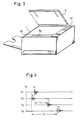
- Figure 3 is a perspective view showing a copying machine equipped with the input device shown in Figure 2, wherein a cover 11 is opened.
- the input device shown in Figure 2 is operated by touching a designated point P (X, Y) on the glass panel 1 with a pen or the like, the shock waves are propagated on the surface of the glass panel I or through it, and reach the respective sensors S1 to S4.
- the resulting timing chart is shown in the graph.
- t0 shows a time when a designated point is touched
- t1 to t4 show times when the sensors S1 to S4 detect the shock waves.
- T1 and T2 show time differences in detection between the sensors S1 and S3, and between the sensors S2 and S4.
- the sensors S1 to S4 convert the vibrations into electrical signals, and if this function is performed, any device such as piezo sensors, strain sensors, or mini-microphones can be used.
- the sensor S1 constitutes part of a detector circuit C1 which includes an amplifier 41, a filter 42, a comparator 43 and a latch 44.
- the vibrations detected by the sensor S1 are converted into electrical signals, and amplified into a predetermined voltage by the amplifier 41.
- the amplified voltage is trimmed by the filter 42 so as to remove unnecessary frequencies.
- the voltage is compared by the comparator 43 and when it reaches a predetermined value or exceeds it, it is detected as an effective signal, which is immediately sent to the latch 44.
- the time at which the effective signal comes out from the latch 44 is detected by a microcomputer (CPU) 45 which generates a reset signal R1, thereby holding the output of the latch 44.
- the circuit C1 is a detector circuit which comprises the arrangement from the sensor S1 to the latch 44.
- circuits C2 to C4 are detector circuits including the sensors S2 to S4, respectively.
- the CPU 45 is connected to a read-only memory (ROM) 46 which stores a required set of programs based on the data required to effect arithmetic calculation for identifying the designated point or points 4 and to execute the copying, the data being received from the input panels 8 and 9.
- the CPU 45 is also connected to a random access memory (RAM) 47 which temporarily stores the detected time of the sensors S1 to S4, the results of the arithmetic calculation for identifying the touched points, the copying data, and the copying state, an input/output port 48 which is used in increasing the number of input and output terminals and controlling same.
- RAM random access memory
- a sensor group 49 including sensors S5 to S x , a key board 50, several driving elements 51, several control elements 52, an aural transmitter 54, and a driver 53 for driving the driving elements 51, the control elements 52 and the aural transmitter 54, and a display device (the liquid crystal display section 10) 55 are connected to the input/output port 48.
- the CPU 45 outputs a signal which latches the latch 44 in the detection circuit C I only when the copying machine is “ready” but does not output when the coping machine is in operation or at a rise-up or warm-up time, herinafter called “rise-up", after it is switched on. During this period of time, even if the sensors S1 to S4 detect vibrations and the effective signals are output by the comparator 43, these signals are ignored. While the copying machine is at a rise-up time or in operation, the sensors S1 to S4 indiscriminately detect every vibration such as vibrations inherent to the copying machine which are caused by the rotation of the photosensitive drum and the operation of various driving mechanism. To avoid detecting unnecessary vibrations, it is devised so that the signal detected by the CPU 45 is detected only at the "ready” state, and found to be effective, and then the arithmetic operation is started so as to identify touched points.
- the program for this arithmetic operation is stored in the ROM 46, wherein the arithmetic operation is conducted by calculating time differences (shown in Figure 4) in detecting vibrations by the sensors S1 to S4.
- the propagating speed of vibrations through the glass panel depends upon the material and the manufacturing method of the glass panel 1, normally 3,000 to 4,500 m/sec, and in soda glass, it is about 4,300 m/sec.
- Time difference T1 in signal reception between the sensors S1 and S3 on the X-axis is equal to a value obtained by dividing the linear distances from the point P to the sensors S1 and S3 by the speed v.
- time difference T2 in signal reception between the sensors S2 and S4 on the Y-axis is equal to a value obtained by dividing the linear distances from the point P to the sensors S1 and S3 by the speed v.
- the coordinate (x, y) of the point P designated by touching can be sought by arithmetic calculation.
- the arithmetic operation is effected by detecting the times t1 to t4 of the sensors S1 to S4 by the CPU 45 in accordance with the program stored in the ROM 46.
- the detection is ignored when the copying machine is at the rise-up time and in operation, and the arithmetic operation on the basis of vibration detection is not executed.
- the copying machine is switched on (start), and the rise-up or warm-up process starts at Flag F1, continuing until the copying machine comes into the "ready" state, where, for example, the fixing section is energized, the photosensitive drum is put into idle rotation (for electrical charging or discharging) and any other preparatory operations are performed (toward the "ready” state). During this period, "Wait” is displayed, and inputs of any touched point are ignored.
- Step 01 is possible to start only when the operation panel is ready to be operated; for example, the copying operation is ready. This corresponds to Flag F2 where a touched input is processed.
- a timer TM starts, which counts by 0.1 ⁇ sec so as to allow an error in the range of ⁇ 1 mm for identifying the position of a touched point.
- the tolerance is reduced to 1 mm or less. This allows a count unit of about 0.1 ⁇ sec.
- Step 02 decides whether or not an effective signal I1 comes from the sensor S1.
- This effective signal means a signal which is recognized by the CPU 45 when it is input from the latch 44 in the detection circuit C1 in Figure 5.
- Step 03 decides whether a detecting Flag F1 is on or not when the signal I1 is detected.
- Step 04 switches on Flag F1 upon detection of the signal I1, and the time of a timer TM is stored in a memory area M1 of the RAM 47 as a detecting time t1. Then, in order to fix the output of the latch 44 to "low", the output R1 of the CPU 45 is turned on.
- Steps 05 to 07 if the signal I1 is not detected at Step 02 or Flag F1 is already on at Step 03 or all proceses at Step 04 are finished, the sequence proceeds to Step 05.
- the time t2 of the sensor S2 is detected by the same procedures followed from Steps 02 to 04.
- Steps 08 to 13 the times t3 and t4 of the sensors S3 and S4 are detected by the same manner.
- Steps 14 judges Flags F1 to F4 as being on, if the detection of all the times t1 to t4 is finished from Steps 02 to 13, the sequence proceeds to Step 15. If any of the times t1 to t4 is not detected, the sequence returns to Step 20, and the time detecting program resumes from Steps 02 to 14.
- Step 15 turns on the aural transmitter 54 when the detection of all the times t1 to t4 are finished, thereby informing the operator of the completion of the signal inputs.
- the CPU 45 executes the process shown in the flowchart of Figure 7, and arithmetically processes the time t1 in accordance with the equations (3) and (4). Thus, the coordinate (x, y) of the point P designated by touching is obtained.
- Step 16 the time t3 stored in the RAM 47 is deducted from time t1, and a time difference T1 in detection between the sensors S1 and S3 on the X-axis is obtained, and the results are stored in a memory area M5 of the RAM 47.
- Step 17 a time difference T2 in detection between the sensors S2 and S4 on the Y-axis is obtained, and the results are stored in a memory area M6 of the RAM 47.
- Step 18 x is calculated by equation (3) and at Step 19 y is calculated by equation (4).
- Step 20 it is judged to decide which is earlier detected, the time t1 or t3. If the time t1 is earlier detected, the calculated value x is stored as a plus value in a memory area M x of the RAM 47. If the time t3 is earlier detected, the x is stored as a minus value in a memory area M x of the RAM 47.
- Step 23 decides which is earlier detected, the time t2 or t4. If the time t2 is earlier detected, at Step 25 the calculated value y is stored as a plus value in a memory area M y of the RAM 47. If the time t4 is earlier detected, at Step 25 the calculated value y is stored as a minus value in a memory area M y of the RAM 47.
- the coordinate (x, y) of the point P designated by touching is determined, and is stored in a memory area of the RAM 47.
- the position of the point P is identified on the glass panel 1 by reference to the program whereby the input comes from the input panels 8, 9 or from the first area 2.
- the last-mentioned determination is effected; for example, by setting the center of the first area 2 as the origin 0 (0, 0), and detecting whether the touching occurs within the coordinates (-X10 to X10, -Y n-1 to Y10). If it is found to originate from within these coordinate, it is judged that it comes from the first area 2.
- the input panels 8 and 9 are printed at places away from the first area 2, that is, at the right side of the sensor S1 (L ⁇ X10, where L is on the X-axis), and downward of the sensor S1 (-L ⁇ -Y n , where -L is on the Y-axis).
- the K1 to X n on the input panel 8 are input keys whereby copying data such as the designation of a designated area for an original and the selection of copying modes, are input, wherein the key K n is allotted to the operation of the copyings. Therefore, K1 can optionally allocated to regions Y10, and K2 is allocated to regions Y9 to Y8.
- the value 1 corresponds to a region -X2 to -X1
- the value 2 corresponds to a region -X1 to
- the value 3 corresponds to a region 0 to X1 and so on.
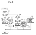
- Figure 9 shows a flowchart whereby it is judged which region in the RAM 47 the position calculated in Figure 7 belongs to, thereby detecting whether the signal is input as a key input from the input panels 8 and 9 or else as a designation of area. Moreover, the input key is also identified in the memory.
- the value of the counter i is set to 1.
- This counter i shows an area within the input panel 8, and corresponds to the number of keys in the input panel 8.
- the counter has a range from 1 to n so as to correspond to the keys K1 to K n of the input panel 8 allotted to the coordinates Y10 to Y n .
- the ROM 46 reads the coordinates Y10 to Y n which correspond to the number of the counter i.
- Step 31 decides whether the M x on the X-axis for the detected point P is larger than the X10 stored in the ROM 46. If it is found to be larger, Step 32 decides whether the M y on the Y-axis is between the Y10 and Y9 stored in the ROM 46.
- Step 35 decides whether the counter i exceeds the number of keys. If it does not exceed it, the sequence returns to Step 32 where it is decided whether it is between Y9 and Y8. If it is between Y9 and Y8, Step 33 decides that it is key K2.
- Step 36 decides that an exact region has not been designated if the counter i exceeds, and displays "input again” through the display 55.
- Steps 37 to 42 shows a flowchart whereby it is detected that the ten-key key board 9-1 and the display 10 are designated. In the same manner as Steps 32 and 36 any of the keys KY1 to KY m has been designated.
- Step 43 if the values of M x and M y are found to be below X10 and Y10 at Steps 31 and 37, the coordinate (M x , M y ) of the point P designated by touching is displayed on the display 55 as numerals corresponding to the scales 13 and 14 printed along the glass panel 1, wherein the point, P is evidently designated by touching in the first area 2. If two touched points are found, the rectangle having a diagonal as shown in Figure 1 is input as a signal area.
- the signal input device can perform level inputting, that is, input data about an image area of an original and other copying data to the copying machine from surface to surface.
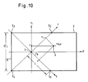
- Figure 10 shows a further example 14 which sensors S3 and S4 located adjacent to each end of the reference line 6 of the glass panel 1, which are boundaries of the first area 2), and S1 and S2 located at two apexes of a square with a side extending from S3 to S4 and arranged in a counter-clockwise direction.
- the origin is placed at the center of this square, and the OS1 is the X-axis, and OS2 is the Y-axis.
- a touched point P has the coordinate (x, y).
- the sensors in which they are arranged on the boundaries of an image area, so that they do not prevent the formation of an image.
- the sensors are located on the boundaries of the first area 2 on the glass panel 1, precision is achieved.
Description
- The present invention relates to a signal input device which comprises an operation panel including an input area in which data are input by touching a point on the operation panel and a plurality of sensors located at different places on the operation panel for receiving vibrations propagated from a touched point on the operation panel, respectively.
- Such a signal input device is known from JP-A-63244068.
- Various methods are in use for inputting data as signals:
- One method is to use a key board on which data are input by keys. Each key is provided with a sensor (e.g. a contact switch) for detecting the input. This method is mainly used in electronic appliances. Another method is to use, in addition to the key board, a signal input device designed to designate an image-reading area or an image-non-reading area. This type of signal input devices adopt the following methods:
- One method is for an operator to overlap a copying image on a lattice-scaled transparent sheet, and read the scales on the X-axis and Y-axis so as to input point by point through a ten-key key board.
- Another is to mark scales along the X-axis and Y-axis on a glass plate on which an original is placed, and read the scales so as to enable an operator to input in response to points designated through a ten-key key board.
- A third method is to provide arrays of switches equally spaced along the X-axis and Y-axis, respectively on an original glass plate and enable an operator to input a coordinate designated by switches.
- A fourth method is to provide a planar matrix array sensor on a cover covering an original, and to input into the sensor by an input pen.
- The first and second methods can be economically achieved, but are not efficient in operation. The third method is also inefficient because of the dual operations of the X-axis and Y-axis.
- The fourth method is more efficient than the other methods but disadvantageously costly because of the expensive matrix array. In addition, the glass plate must be completely transparent and exactly flat so as to avoid erroneous readings, and therefore, a special tray or the like must be used for supporting the matrix array sensor. The original must be shifted from the glass plate to the tray.
- The above mentioned JP-A-63244068 proposes a device which is used in cooperation with a ready-made original glass plate so as to designate copying parts of the original placed on the glass plate. This device includes an input pen incorporating an oscillator and at least three vibration detectors around the glass plate. When an operator touches the original glass plate with the input pen, the three detectors detect time intervals on the basis of reception of signals from the touching point so as to evaluate the location of the touching points. The above mentioned JP-A-63244068 does not disclose a means or structure for identifying the touched points in detail but it is presumed that the cost will be reduced because a ready-made glass plate is used, and no key input device or matrix array is required.
- The first and fourth method require an extra input device for inputting copying data in addition to a key input device for designating the inputting areas. The JP-A-63244068 discloses the designation of an inputting area but fails to disclose that the glass plate is used as the input device. In particular JP-A-63244068 describes that the input pen is electrically connected to the driving circuit of the input device which drives the oscillating element.
- Also Research Disclosure No. 291, July 1988, Havant GB, page 494, XP000005104 NN "Document view screen" describes the use of a Sonic pen which is electrically connected to the input device by means of a connecting wire. Also this document does not refer as to how the coordinate values of the touched points are obtained.
- It is an object of the present invention to provide a signal input device which overcomes the above-discussed and numerous other disadvantages and deficiencies of the prior art.
- This object is solved in accordance with the invention by a signal input device comprising:
- an operation panel including an input area in which data are input by touching a point on the operation panel, and
- a plurality of sensors located at different places on the operation panel for receiving vibrations propagated from a touched point on the operation panel, respectively, and which is characterized by a time counting means which starts to count time when one of the sensors receives the respective vibration;
- a detection means for detecting times at which the sensors receive the vibrations and for obtaining time differences between the detected times by using the time counting means;
- an arithmetic means for identifying the position of the touched point on the basis of the time differences;
- a memory means for storing data of numerical values whereby the input area is divided into a plurality of minor areas; and
- a means for judging, to which one of the minor areas the touched points belongs on the basis of the arithmetic results indication the positions of the touched point and data of the numerical values (claim 1).
- Depending
claims 2 to 8 are each specifying advantageous developments thereof. - Thus, the invention described herein makes possible the objectives of (1) providing a signal input device which eliminates the necessity of providing switches and/or sensors corresponding to operation keys, (2) providing a planar type of signal input device, and (3) providing a signal input device which can easily be attached to a copying machine.
- This invention may be better understood and its numerous objects and advantages will become apparent to those skilled in the art by reference to the accompanying drawings as follows:
- Figure 1 is a plan view showing a copying machine equipped with a signal input device of the present invention on the original glass plate thereof;
- Figure 2 is a plan view showing another example of the signal input device of the present invention;
- Figure 3 is a perspective view showing a copying machine equipped with the signal input device of Figure 2;
- Figure 4 is a timing chart showing the operation of the signal input device of Figure 2, particularly to show shock waves being transmitted through the surface of a table glass or the substance thereof and reaching sensors;
- Figure 5 is a block diagram used for the signal input device and the circuit of a copying machine;
- Figure 6 is a flowchart exemplifying the steps of timing detection in the range of t₁ to t₄ in Figure 4;
- Figure 7 is a flowchart showing the steps for seeking coordinates (X, Y) of designated points through arithmetic operation of the times t₁ to t₄ obtained from the flowchart of Figure 6;
- Figure 8 is a flowchart showing the steps to be taken for detecting designated points prior to signal inputting;
- Figure 9 is a flowchart showing the steps for checking areas where the detected input points are situated; and
- Figure 10 is a top surface view showing another method of detecting input points.
- Referring to Figure 1, there is provided a
transparent glass panel 1 having afirst area 2 in which an original 3 can be copied. If the original 3 is placed out of thefirst area 2, it cannot be copied. A designatingarea 4 is provided, havingdiagonals 5 and 5'. Thereference numeral 6 designates a reference line along which the forward end of the original 3 is placed, and thereference numeral 7 designates an index which indicates the center line of an image to be reproduced as the origin (0, 0). - An
input panel 8 is located on the right side of the copying machine, through which various copying data and other necessary data are input. Theinput panel 8 is provided by printing on the top surface or the back surface of theglass panel 1. Necessary items are printed thereon. Theinput panel 8 can include several sections depending upon functions, such as sections A and B both for designating input points, sections C to F for designating treating modes, such as trimming, masking, centering, color designation, and section G for selecting color in accordance with the designation of a mode by the section F. In addition, it is possible to provide a ten-key key board for inputting digital data by a printing method. Theglass panel 1 is additionally provided withreference scales - Sensors S₁ to S₄ are directly stuck to the front surface or the back surface of the
glass panel 1 at each corner. These sensors S₁ to S₄ are to detect touched points by sensing vibrations propagated from the touched point; more specifically, the sensors detect the times for receiving signals. - An original is placed on the glass panel I whereby a designated
point 5 of the original is input as a position signal to the copying machine. In this way a copying area is designated. Apart from this manner of designation, it is also possible to input copying data to the copying machine through theinput panel 8, as follows: - Any point is touched on the
glass panel 1, from which vibrations are propagated to each sensors S₁ to S₄. The sensors S₁ to S₄ detect or receive the vibrations at different times depending upon the distances from the touched points. The position of a touched point can be calculated by reference to a reference point; for example, theindex 7. In this way, it is possible to recognize whether it is a touched point entered in theinput panel 8 or thefirst area 2. In addition, theinput panel 8 enables the operator to identify the particular position in theinput panel 8 to be input by touching. - An operation of the signal input device of the present invention will be described as an example when it is used in a copying machine:
- Step 1: An original 3 is placed in the
first area 2 with the center line thereof aligned with theindex 7 and with one edge thereof lying along thereference line 6. - Step 2: The start area in the section A is touched by a pen, and then a state is reached in which the position of the original 3 can be designated. The designated
area 4 is set by touching the twopoints 5 and 5'. When a plurality of designated areas are to be set, the above-mentioned procedure is repeated. - Step 3: When the designation is finished, the section B is touched so as to input the data obtained by
Step 2 to the copying machine. - Step 4: Various treating modes such as trimming, masking, centering, color designating, etc, are operable on the original 3 after the position is designated by the above-mentioned procedure. These modes can be input in the respective sections C to F.
- Then, the original 3 is turned upside down on the
copiable area 2. The turned original 3 is set by being placed alongside thereference line 6, and then the print switch on the copying machine is pressed. In this way the copying is carried out in an input mode. - Referring to Figure 2, a modified example of the embodiment will be described:
- The sensors S₁ to S₄ are provided at the center of each side of the
first area 2, slightly spaced outside the respective sides. Twoinput panels 8 and 9 are provided on two sides (in Figure 2, the lower and the right sides) by printing so as to enable an operator to input by key. These twoinput panels 8 and 9 are provided on thesame glass panel 1. The sensors S₁ and S₃ are on the X-axis and the sensors S₂ and S₄ are on the Y-axis, so as to locate the origin (0, 0) at the center of thefirst area 2. - The copying machine is equipped with an input section on the glass panel I through which required copying data are input, and a liquid
crystal display section 10 is also provided. By touching the display, desired data can be input as displayed. - The input panel 9 includes a sections 9-1 and 9-2 for inputting digital data and starting the copying operation, respectively. The sections 9-1 and 9-2 are printed on the
glass panel 1. The input data are displayed on the liquidcrystal display section 10. - Figure 3 is a perspective view showing a copying machine equipped with the input device shown in Figure 2, wherein a
cover 11 is opened. - Referring to Figure 4, the input device shown in Figure 2 is operated by touching a designated point P (X, Y) on the
glass panel 1 with a pen or the like, the shock waves are propagated on the surface of the glass panel I or through it, and reach the respective sensors S₁ to S₄. The resulting timing chart is shown in the graph. t₀ shows a time when a designated point is touched, and t₁ to t₄ show times when the sensors S₁ to S₄ detect the shock waves. T₁ and T₂ show time differences in detection between the sensors S₁ and S₃, and between the sensors S₂ and S₄. - Referring to Figure 5, a circuit included in & copying machine equipped with the input device of the present invention will be described:
- The sensors S₁ to S₄ convert the vibrations into electrical signals, and if this function is performed, any device such as piezo sensors, strain sensors, or mini-microphones can be used.
- The sensor S₁ constitutes part of a detector circuit C₁ which includes an
amplifier 41, afilter 42, acomparator 43 and alatch 44. The vibrations detected by the sensor S₁ are converted into electrical signals, and amplified into a predetermined voltage by theamplifier 41. The amplified voltage is trimmed by thefilter 42 so as to remove unnecessary frequencies. Then the voltage is compared by thecomparator 43 and when it reaches a predetermined value or exceeds it, it is detected as an effective signal, which is immediately sent to thelatch 44. The time at which the effective signal comes out from thelatch 44 is detected by a microcomputer (CPU) 45 which generates a reset signal R₁, thereby holding the output of thelatch 44. The circuit C₁ is a detector circuit which comprises the arrangement from the sensor S₁ to thelatch 44. Likewise, circuits C₂ to C₄ are detector circuits including the sensors S₂ to S₄, respectively. - In addition, the
CPU 45 is connected to a read-only memory (ROM) 46 which stores a required set of programs based on the data required to effect arithmetic calculation for identifying the designated point or points 4 and to execute the copying, the data being received from theinput panels 8 and 9. TheCPU 45 is also connected to a random access memory (RAM) 47 which temporarily stores the detected time of the sensors S₁ to S₄, the results of the arithmetic calculation for identifying the touched points, the copying data, and the copying state, an input/output port 48 which is used in increasing the number of input and output terminals and controlling same. Asensor group 49 including sensors S₅ to Sx, akey board 50, several drivingelements 51,several control elements 52, anaural transmitter 54, and adriver 53 for driving the drivingelements 51, thecontrol elements 52 and theaural transmitter 54, and a display device (the liquid crystal display section 10) 55 are connected to the input/output port 48. - The
CPU 45 outputs a signal which latches thelatch 44 in the detection circuit CI only when the copying machine is "ready" but does not output when the coping machine is in operation or at a rise-up or warm-up time, herinafter called "rise-up", after it is switched on. During this period of time, even if the sensors S₁ to S₄ detect vibrations and the effective signals are output by thecomparator 43, these signals are ignored. While the copying machine is at a rise-up time or in operation, the sensors S₁ to S₄ indiscriminately detect every vibration such as vibrations inherent to the copying machine which are caused by the rotation of the photosensitive drum and the operation of various driving mechanism. To avoid detecting unnecessary vibrations, it is devised so that the signal detected by theCPU 45 is detected only at the "ready" state, and found to be effective, and then the arithmetic operation is started so as to identify touched points. - Any point P designated by touching is identified by arithmetic calculation in the following manner:
- The program for this arithmetic operation is stored in the
ROM 46, wherein the arithmetic operation is conducted by calculating time differences (shown in Figure 4) in detecting vibrations by the sensors S₁ to S₄. - In Figure 2, suppose that the coordinates of the sensors S₁ to S₄ are respectively (L, O), (O, L), (-L, O) and (O, -L), and that the coordinate of the designated point is (x, y). Vibrations are supposed to propagate through the
glass panel 1 at a speed of v m/sec. - The propagating speed of vibrations through the glass panel depends upon the material and the manufacturing method of the
glass panel 1, normally 3,000 to 4,500 m/sec, and in soda glass, it is about 4,300 m/sec. - Time difference T₁ in signal reception between the sensors S₁ and S₃ on the X-axis is equal to a value obtained by dividing the linear distances from the point P to the sensors S₁ and S₃ by the speed v. This relationship is expressed by the following equation:

- Likewise, time difference T₂ in signal reception between the sensors S₂ and S₄ on the Y-axis is equal to a value obtained by dividing the linear distances from the point P to the sensors S₁ and S₃ by the speed v. This relationship is expressed by the following equation:

- The equations (1) and (2) are simplified as follows:


- From the equations (3) and (4), x and y are expressed by the following equations (5) and (6):


- In the equations (5) and (6)

- On the basis of the above-mentioned equations, the coordinate (x, y) of the point P designated by touching can be sought by arithmetic calculation. The arithmetic operation is effected by detecting the times t₁ to t₄ of the sensors S₁ to S₄ by the
CPU 45 in accordance with the program stored in theROM 46. - Referring to Figures 6 to 8, the manner of detecting the times t₁ to t₄ will be described:
- As described above, the detection is ignored when the copying machine is at the rise-up time and in operation, and the arithmetic operation on the basis of vibration detection is not executed.
- In Figure 8, the copying machine is switched on (start), and the rise-up or warm-up process starts at Flag F₁, continuing until the copying machine comes into the "ready" state, where, for example, the fixing section is energized, the photosensitive drum is put into idle rotation (for electrical charging or discharging) and any other preparatory operations are performed (toward the "ready" state). During this period, "Wait" is displayed, and inputs of any touched point are ignored.
- When the copying operation is ready, "Ready" is displayed, and the sequence proceeds to the next Flag F₂. When a touched input is detected, it is judged to see if it arises in the printer start section. If it is not, the touching input is again detected. If any area designation or copying data are input, the corresponding process is executed, and a touching input is detected. When the touching input is judged to be the printer start signal, Flag F₃ is executed so as to start the copying operation under the previously input copying data and the point designation. At this stage and thereafter until the copying operation is finished and the "Ready" state is restored, any touching input is ignored.
- The treatment of a touched input at Flag F₂ will be described in detail by reference to Figure 6:
- Step 01 is possible to start only when the operation panel is ready to be operated; for example, the copying operation is ready. This corresponds to Flag F₂ where a touched input is processed.
- When the sequence is started, a timer TM starts, which counts by 0.1 µsec so as to allow an error in the range of ± 1 mm for identifying the position of a touched point. The reason is as follows:

- If the times sensed by the sensors are detected at two or more cycles, the tolerance is reduced to 1 mm or less. This allows a count unit of about 0.1 µsec.
- Step 02 decides whether or not an effective signal I₁ comes from the sensor S₁. This effective signal means a signal which is recognized by the
CPU 45 when it is input from thelatch 44 in the detection circuit C₁ in Figure 5. - Step 03 decides whether a detecting Flag F₁ is on or not when the signal I₁ is detected.
- Step 04 switches on Flag F₁ upon detection of the signal I₁, and the time of a timer TM is stored in a memory area M₁ of the
RAM 47 as a detecting time t₁. Then, in order to fix the output of thelatch 44 to "low", the output R₁ of theCPU 45 is turned on. - At Steps 05 to 07, if the signal I₁ is not detected at Step 02 or Flag F₁ is already on at Step 03 or all proceses at Step 04 are finished, the sequence proceeds to Step 05. The time t₂ of the sensor S₂ is detected by the same procedures followed from Steps 02 to 04.
- At Steps 08 to 13, the times t₃ and t₄ of the sensors S₃ and S₄ are detected by the same manner.
-
Steps 14 judges Flags F₁ to F₄ as being on, if the detection of all the times t₁ to t₄ is finished from Steps 02 to 13, the sequence proceeds to Step 15. If any of the times t₁ to t₄ is not detected, the sequence returns to Step 20, and the time detecting program resumes from Steps 02 to 14. -
Step 15 turns on theaural transmitter 54 when the detection of all the times t₁ to t₄ are finished, thereby informing the operator of the completion of the signal inputs. - In this way the times t₁ to t₄ at which the sensors S₁ to S₄ detect vibrations propagated from a touched point on the glass table 1 are recognized by the
CPU 45, and the detected time t₄ is stored in theRAM 47. - The
CPU 45 executes the process shown in the flowchart of Figure 7, and arithmetically processes the time t₁ in accordance with the equations (3) and (4). Thus, the coordinate (x, y) of the point P designated by touching is obtained. - At
Step 16, the time t₃ stored in theRAM 47 is deducted from time t₁, and a time difference T₁ in detection between the sensors S₁ and S₃ on the X-axis is obtained, and the results are stored in a memory area M₅ of theRAM 47. - At Step 17, a time difference T₂ in detection between the sensors S₂ and S₄ on the Y-axis is obtained, and the results are stored in a memory area M₆ of the
RAM 47. - At Step 18 x is calculated by equation (3) and at Step 19 y is calculated by equation (4). At
Step 20 it is judged to decide which is earlier detected, the time t₁ or t₃. If the time t₁ is earlier detected, the calculated value x is stored as a plus value in a memory area Mx of theRAM 47. If the time t₃ is earlier detected, the x is stored as a minus value in a memory area Mx of theRAM 47. - Step 23 decides which is earlier detected, the time t₂ or t₄. If the time t₂ is earlier detected, at
Step 25 the calculated value y is stored as a plus value in a memory area My of theRAM 47. If the time t₄ is earlier detected, atStep 25 the calculated value y is stored as a minus value in a memory area My of theRAM 47. - In this way, the coordinate (x, y) of the point P designated by touching is determined, and is stored in a memory area of the
RAM 47. The position of the point P is identified on theglass panel 1 by reference to the program whereby the input comes from theinput panels 8, 9 or from thefirst area 2. The last-mentioned determination is effected; for example, by setting the center of thefirst area 2 as the origin 0 (0, 0), and detecting whether the touching occurs within the coordinates (-X₁₀ to X₁₀, -Yn-1 to Y₁₀). If it is found to originate from within these coordinate, it is judged that it comes from thefirst area 2. - The
input panels 8 and 9 are printed at places away from thefirst area 2, that is, at the right side of the sensor S₁ (L < X₁₀, where L is on the X-axis), and downward of the sensor S₁ (-L < -Yn, where -L is on the Y-axis). The K₁ to Xn on theinput panel 8 are input keys whereby copying data such as the designation of a designated area for an original and the selection of copying modes, are input, wherein the key Kn is allotted to the operation of the copyings. Therefore, K₁ can optionally allocated to regions Y₁₀, and K₂ is allocated to regions Y₉ to Y₈. - In the input panel 9, it is arranged that the
value 1 corresponds to a region -X₂ to -X₁, thevalue 2 corresponds to a region -X₁ to 0, thevalue 3 corresponds to aregion 0 to X₁ and so on. These regions are previously stored in theROM 46, in which items corresponding to the respective regions are stored. - Referring to Figure 9, a signal input will be described at a point P designated by touching. Figure 9 shows a flowchart whereby it is judged which region in the
RAM 47 the position calculated in Figure 7 belongs to, thereby detecting whether the signal is input as a key input from theinput panels 8 and 9 or else as a designation of area. Moreover, the input key is also identified in the memory. - At
Step 30 the value of the counter i is set to 1. This counter i shows an area within theinput panel 8, and corresponds to the number of keys in theinput panel 8. The counter has a range from 1 to n so as to correspond to the keys K₁ to Kn of theinput panel 8 allotted to the coordinates Y₁₀ to Yn. TheROM 46 reads the coordinates Y₁₀ to Yn which correspond to the number of the counter i. - Step 31 decides whether the Mx on the X-axis for the detected point P is larger than the X₁₀ stored in the
ROM 46. If it is found to be larger, Step 32 decides whether the My on the Y-axis is between the Y₁₀ and Y₉ stored in theROM 46. - At Step 34, if it is found to be between the Y₁₀ and Y₉, Step 33 decides that it is the
key 1. If it is not between the Y₁₀ and Y₉, Step 33 adds "1" to the counter i so as to achieve (i = 2). -
Step 35 decides whether the counter i exceeds the number of keys. If it does not exceed it, the sequence returns to Step 32 where it is decided whether it is between Y₉ and Y₈. If it is between Y₉ and Y₈, Step 33 decides that it is key K₂. - The above-mentioned judgement is repeated until the counter i becomes n, thereby enabling any of the keys K₁ to Kn to be designated.
- Step 36 decides that an exact region has not been designated if the counter i exceeds, and displays "input again" through the
display 55. - Steps 37 to 42 shows a flowchart whereby it is detected that the ten-key key board 9-1 and the
display 10 are designated. In the same manner as Steps 32 and 36 any of the keys KY₁ to KYm has been designated. - At
Step 43, if the values of Mx and My are found to be below X₁₀ and Y₁₀ at Steps 31 and 37, the coordinate (Mx, My) of the point P designated by touching is displayed on thedisplay 55 as numerals corresponding to thescales glass panel 1, wherein the point, P is evidently designated by touching in thefirst area 2. If two touched points are found, the rectangle having a diagonal as shown in Figure 1 is input as a signal area. - In this way the position of the glass panel is identified by a point designated by touching the glass panel, and a signal is input corresponding to the designated area. The signal input device can perform level inputting, that is, input data about an image area of an original and other copying data to the copying machine from surface to surface.
- Figure 10 shows a further example 14 which sensors S₃ and S₄ located adjacent to each end of the
reference line 6 of theglass panel 1, which are boundaries of the first area 2), and S₁ and S₂ located at two apexes of a square with a side extending from S₃ to S₄ and arranged in a counter-clockwise direction. The origin is placed at the center of this square, and the OS₁ is the X-axis, and OS₂ is the Y-axis. In the coordinates a touched point P has the coordinate (x, y). The direction from a middle point between the sensors S₃ and S₄ to theorigin 0 is X', and the direction perpendicular to the X'-axis and extending from theorigin 0 to a middle point between the sensors S₂ and S₃ is Y'-axis. Suppose that the coordinate of the point P on the X' and Y' axes is (X, Y). Then, an angle XOX' θ becomes 45°, and the following equations are established, which can be used for converting the coordinate in Figure 2:

- By using these equations (8) and (9), the position of the point P can be calculated in the same arithmetic manner as described with respect to Figure 2.
- Under this arrangement of the sensors, in which they are arranged on the boundaries of an image area, so that they do not prevent the formation of an image. In addition, since the sensors are located on the boundaries of the
first area 2 on theglass panel 1, precision is achieved.
Claims (9)
- A signal input device comprising:an operation panel including an input area (2) in which data are input by touching a point on the operation panel, anda plurality of sensors (S1-S4) located at different places on the operation panel for receiving vibrations propagated from a touched point on the operation panel, respectively, characterized by a time counting means (TM) which starts to count time when one of the sensors receives the respective vibration;a detection means for detecting times at which the sensors receive the vibrations and for obtaining time differences between the detected times by using the time counting means;an arithmetic means (45) for identifying the position of the touched point on the basis of the time differences;a memory means (46, 47) for storing data of numerical values whereby the input area (2) is divided into a plurality of minor areas; anda means for judging, to which one of the minor areas the touched points belongs on the basis of the arithmetic results indication the positions of the touched point and data of the numerical values.
- The signal input device for use in a copying machine according to claim 1, wherein said operation panel comprises a transparent glass panel (1), and said input area (2) has a first area (2) in which an original (3) is placed and a second area in which the original (3) is not placed;said plurality of sensors (S1-S4) are located at the second area, the second area of the glass panel being defined as an input area for allowing copying data to be input;said judging means are deciding whether the position of a touched point identified by the arithmetic means is in the first area or not, on the basis of the data stored in the memory means (46, 47); anda control means for using the result obtained by the judging means as input about the original when it originates from the first area and as input of copying data when it originates from the second area.
- The signal input device according to claims 1 or 2, wherein the operation panel has a front surface and a back surface, and the sensors (S1-S4) are located at the front surface.
- The signal input device according to claims 1 or 2, wherein the operation panel has a front surface and a back surface, and the sensors (S1-S4) are located at the back surface.
- The signal input device according to claims 1 or 2, wherein the sensors (S1-S4) are located adjacent to boundaries (6) of the first area (2).
- The signal input device according to claims 1 or 2, wherein the touched point is designated by a pen.
- The signal input device according to claims 1 or 2, wherein the memory means (46, 47) stores a propagating speed of the vibration through the operation glass panel and distances between two respective sensors, and the propagating speed and the distances are used for identifying the position of the touched point by the arithmetic means.
- The signal input device according to one of the preceding claims, wherein the operation panel is rectangular, the sensors (S1-S4) comprise a first, a second, a third and a fourth sensor, which are arranged in the vicinity of corners of the operation panel in a counterclockwise direction, and the detection means obtains the time differences between the detected times of the first and the third sensors and between the detected times of the second and the fourth sensors.
- The signal input device in accordance with claim 2, wherein the arithmetic means comprises a means for starting the arithmetic operation by treating the detected times as effective when the copying machine is in a stable operation state.
Applications Claiming Priority (4)
| Application Number | Priority Date | Filing Date | Title |
|---|---|---|---|
| JP23878890 | 1990-09-06 | ||
| JP238788/90 | 1990-09-06 | ||
| JP188650/91 | 1991-07-29 | ||
| JP18865091A JP3111087B2 (en) | 1990-09-06 | 1991-07-29 | Signal input device |
Publications (3)
| Publication Number | Publication Date |
|---|---|
| EP0474232A2 EP0474232A2 (en) | 1992-03-11 |
| EP0474232A3 EP0474232A3 (en) | 1993-02-24 |
| EP0474232B1 true EP0474232B1 (en) | 1996-04-24 |
Family
ID=26505055
Family Applications (1)
| Application Number | Title | Priority Date | Filing Date |
|---|---|---|---|
| EP91115018A Expired - Lifetime EP0474232B1 (en) | 1990-09-06 | 1991-09-05 | Transparent touch-sensitive panel |
Country Status (4)
| Country | Link |
|---|---|
| US (1) | US5717432A (en) |
| EP (1) | EP0474232B1 (en) |
| JP (1) | JP3111087B2 (en) |
| DE (1) | DE69119001T2 (en) |
Families Citing this family (34)
| Publication number | Priority date | Publication date | Assignee | Title |
|---|---|---|---|---|
| JPH05265636A (en) * | 1992-03-17 | 1993-10-15 | Sharp Corp | Device for compensating plotting input |
| FR2697935B1 (en) * | 1992-11-12 | 1995-01-13 | Sextant Avionique | Compact and ergonomic communication terminal with proximity detection surfaces. |
| JPH09114591A (en) * | 1995-10-12 | 1997-05-02 | Semiconductor Energy Lab Co Ltd | Liquid crystal display and its display method |
| JP3551591B2 (en) * | 1995-12-27 | 2004-08-11 | 富士ゼロックス株式会社 | Pen input device |
| JPH1091316A (en) * | 1996-09-17 | 1998-04-10 | Sharp Corp | Coordinate input device and program recording medium therefor |
| FR2755269B1 (en) * | 1996-10-25 | 1998-12-04 | Asulab Sa | DEVICE FOR IDENTIFYING A MANUAL ACTION ON A SURFACE, ESPECIALLY FOR A WATCHMAKING PIECE |
| JP3624070B2 (en) * | 1997-03-07 | 2005-02-23 | キヤノン株式会社 | Coordinate input device and control method thereof |
| SE9800427D0 (en) * | 1998-02-16 | 1998-02-16 | Lennart Christensson | Easy entry for GPS navigation system |
| GB9928682D0 (en) | 1999-12-06 | 2000-02-02 | Electrotextiles Comp Ltd | Input apparatus and a method of generating control signals |
| US7157649B2 (en) * | 1999-12-23 | 2007-01-02 | New Transducers Limited | Contact sensitive device |
| GB0116310D0 (en) | 2001-07-04 | 2001-08-29 | New Transducers Ltd | Contact sensitive device |
| ATE557337T1 (en) | 2002-02-06 | 2012-05-15 | Soundtouch Ltd | TOUCH PAD |
| FR2841022B1 (en) | 2002-06-12 | 2004-08-27 | Centre Nat Rech Scient | METHOD FOR LOCATING AN IMPACT ON A SURFACE AND DEVICE FOR IMPLEMENTING SAID METHOD |
| US6871149B2 (en) * | 2002-12-06 | 2005-03-22 | New Transducers Limited | Contact sensitive device |
| US7573466B1 (en) * | 2003-09-17 | 2009-08-11 | Rockwell Collins, Inc. | Method and apparatus for data entry for a liquid crystal display |
| US7309287B2 (en) * | 2003-12-10 | 2007-12-18 | Nintendo Co., Ltd. | Game machine having display screen with touch panel |
| US7578742B2 (en) * | 2004-03-26 | 2009-08-25 | Nintendo Co., Ltd. | Recording medium storing video game program and video game device |
| JP4574441B2 (en) * | 2004-06-07 | 2010-11-04 | キヤノン株式会社 | Image forming apparatus and control method thereof |
| US20060073891A1 (en) * | 2004-10-01 | 2006-04-06 | Holt Timothy M | Display with multiple user privacy |
| US8106888B2 (en) * | 2004-10-01 | 2012-01-31 | 3M Innovative Properties Company | Vibration sensing touch input device |
| US20060139339A1 (en) * | 2004-12-29 | 2006-06-29 | Pechman Robert J | Touch location determination using vibration wave packet dispersion |
| US7499039B2 (en) * | 2005-01-10 | 2009-03-03 | 3M Innovative Properties Company | Iterative method for determining touch location |
| US7683890B2 (en) * | 2005-04-28 | 2010-03-23 | 3M Innovative Properties Company | Touch location determination using bending mode sensors and multiple detection techniques |
| ITTO20050569A1 (en) * | 2005-08-09 | 2007-02-10 | St Microelectronics Srl | DEVICE AND METHOD OF DETERMINING THE CONTACT POSITION AND CONTACT SENSITIVE ELECTRONIC DEVICE |
| WO2010024030A1 (en) * | 2008-08-29 | 2010-03-04 | 日本電気株式会社 | Information input device, information input method, and information input program |
| US8842097B2 (en) | 2008-08-29 | 2014-09-23 | Nec Corporation | Command input device, mobile information device, and command input method |
| JP5407384B2 (en) * | 2009-02-06 | 2014-02-05 | 富士ゼロックス株式会社 | Image forming apparatus |
| US8525784B2 (en) * | 2009-02-20 | 2013-09-03 | Seiko Epson Corporation | Input device for use with a display system |
| EP2417514A1 (en) * | 2009-04-06 | 2012-02-15 | 3M Innovative Properties Company | Touch sensor with modular sensing components |
| TWI448931B (en) * | 2009-10-16 | 2014-08-11 | Casio Computer Co Ltd | Indicated position detecting apparatus and indicated position detecting method |
| JP5639489B2 (en) * | 2011-01-25 | 2014-12-10 | キヤノン株式会社 | Information processing apparatus, control method therefor, program, and storage medium |
| JP2015089673A (en) * | 2013-11-07 | 2015-05-11 | キヤノン株式会社 | Image formation apparatus |
| EP3117879A1 (en) | 2015-07-14 | 2017-01-18 | Haute Ecole d'Ingénierie et de Gestion du Canton de Vaud (HEIG-VD) | Ball game training system |
| GB2574144B (en) | 2017-02-22 | 2022-06-29 | Beacon Street Innovations Llc | Refreshable braille display |
Family Cites Families (11)
| Publication number | Priority date | Publication date | Assignee | Title |
|---|---|---|---|---|
| JPS62284419A (en) * | 1986-05-31 | 1987-12-10 | Toshiba Corp | Input device |
| JPS63182731A (en) * | 1987-01-26 | 1988-07-28 | Canon Inc | Input device for electronic equipment |
| JPH07121059B2 (en) * | 1987-03-03 | 1995-12-20 | キヤノン株式会社 | Image processing device |
| DE3809677A1 (en) * | 1987-03-19 | 1988-12-01 | Toshiba Kk | DISPLAY AND INPUT DEVICE |
| JP2658039B2 (en) * | 1987-03-20 | 1997-09-30 | キヤノン株式会社 | Information processing device |
| JPS63244068A (en) * | 1987-03-31 | 1988-10-11 | Canon Inc | Digitizer |
| DE3885521T2 (en) * | 1987-07-01 | 1994-03-17 | Canon Kk | Coordinate input device. |
| JPH01114926A (en) * | 1987-10-28 | 1989-05-08 | Canon Inc | Coordinate input device |
| JP2522514B2 (en) * | 1988-03-10 | 1996-08-07 | シャープ株式会社 | Operation input device |
| US5070325A (en) * | 1988-03-18 | 1991-12-03 | Canon Kabushiki Kaisha | Coordinate input apparatus |
| US5049933A (en) * | 1989-01-27 | 1991-09-17 | Minolta Camera Kabushiki Kaisha | Image edit input device for use in copying machine |
-
1991
- 1991-07-29 JP JP18865091A patent/JP3111087B2/en not_active Expired - Fee Related
- 1991-09-05 DE DE69119001T patent/DE69119001T2/en not_active Expired - Lifetime
- 1991-09-05 EP EP91115018A patent/EP0474232B1/en not_active Expired - Lifetime
-
1995
- 1995-01-20 US US08/376,066 patent/US5717432A/en not_active Expired - Lifetime
Also Published As
| Publication number | Publication date |
|---|---|
| JP3111087B2 (en) | 2000-11-20 |
| EP0474232A2 (en) | 1992-03-11 |
| US5717432A (en) | 1998-02-10 |
| EP0474232A3 (en) | 1993-02-24 |
| DE69119001D1 (en) | 1996-05-30 |
| DE69119001T2 (en) | 1996-12-12 |
| JPH0511919A (en) | 1993-01-22 |
Similar Documents
| Publication | Publication Date | Title |
|---|---|---|
| EP0474232B1 (en) | Transparent touch-sensitive panel | |
| EP1408397A2 (en) | Electronic equipment | |
| EP0561339A1 (en) | Input device and method for calibration thereof | |
| JP2000284911A (en) | Touch panel | |
| JPH04278627A (en) | Touch panel device | |
| US5748182A (en) | Coordinates input apparatus connected to image processing system | |
| EP0274832B1 (en) | Designating means for an image processing apparatus | |
| EP0560260B1 (en) | An input device and a method of inputting data | |
| JP2582094B2 (en) | Operation display control device for copier | |
| JP2981335B2 (en) | RBI input device | |
| JPH07143340A (en) | Image processor | |
| JPH05189126A (en) | Dotting input device | |
| JPH06102721A (en) | Image forming device | |
| JP7103075B2 (en) | Input device and image processing device | |
| JP2621961B2 (en) | Document detection device | |
| JP2736193B2 (en) | Copying machine with dot input device | |
| JP2683357B2 (en) | Data input device | |
| JPH05307435A (en) | Picture area input device | |
| JPH0627777A (en) | Copying device | |
| JPS60146321A (en) | Picture reader | |
| JPH0991095A (en) | Display device with optical touch sensor | |
| JPH03138633A (en) | Image forming device | |
| JPH0981304A (en) | Image processor | |
| JPH03264964A (en) | Copying device | |
| JPH1042104A (en) | Image input device |
Legal Events
| Date | Code | Title | Description |
|---|---|---|---|
| PUAI | Public reference made under article 153(3) epc to a published international application that has entered the european phase |
Free format text: ORIGINAL CODE: 0009012 |
|
| AK | Designated contracting states |
Kind code of ref document: A2 Designated state(s): DE FR GB |
|
| PUAL | Search report despatched |
Free format text: ORIGINAL CODE: 0009013 |
|
| AK | Designated contracting states |
Kind code of ref document: A3 Designated state(s): DE FR GB |
|
| 17P | Request for examination filed |
Effective date: 19930527 |
|
| K1C1 | Correction of patent application (title page) published |
Effective date: 19920311 |
|
| 17Q | First examination report despatched |
Effective date: 19941103 |
|
| GRAA | (expected) grant |
Free format text: ORIGINAL CODE: 0009210 |
|
| AK | Designated contracting states |
Kind code of ref document: B1 Designated state(s): DE FR GB |
|
| REF | Corresponds to: |
Ref document number: 69119001 Country of ref document: DE Date of ref document: 19960530 |
|
| ET | Fr: translation filed | ||
| PLBE | No opposition filed within time limit |
Free format text: ORIGINAL CODE: 0009261 |
|
| STAA | Information on the status of an ep patent application or granted ep patent |
Free format text: STATUS: NO OPPOSITION FILED WITHIN TIME LIMIT |
|
| 26N | No opposition filed | ||
| REG | Reference to a national code |
Ref country code: GB Ref legal event code: IF02 |
|
| PGFP | Annual fee paid to national office [announced via postgrant information from national office to epo] |
Ref country code: GB Payment date: 20090902 Year of fee payment: 19 |
|
| PGFP | Annual fee paid to national office [announced via postgrant information from national office to epo] |
Ref country code: DE Payment date: 20090903 Year of fee payment: 19 |
|
| PGFP | Annual fee paid to national office [announced via postgrant information from national office to epo] |
Ref country code: FR Payment date: 20091012 Year of fee payment: 19 |
|
| GBPC | Gb: european patent ceased through non-payment of renewal fee |
Effective date: 20100905 |
|
| REG | Reference to a national code |
Ref country code: FR Ref legal event code: ST Effective date: 20110531 |
|
| REG | Reference to a national code |
Ref country code: DE Ref legal event code: R119 Ref document number: 69119001 Country of ref document: DE Effective date: 20110401 |
|
| PG25 | Lapsed in a contracting state [announced via postgrant information from national office to epo] |
Ref country code: DE Free format text: LAPSE BECAUSE OF NON-PAYMENT OF DUE FEES Effective date: 20110401 Ref country code: FR Free format text: LAPSE BECAUSE OF NON-PAYMENT OF DUE FEES Effective date: 20100930 |
|
| PG25 | Lapsed in a contracting state [announced via postgrant information from national office to epo] |
Ref country code: GB Free format text: LAPSE BECAUSE OF NON-PAYMENT OF DUE FEES Effective date: 20100905 |