EP0474218A1 - Medical paste syringe, filling method and paste injecting device - Google Patents
Medical paste syringe, filling method and paste injecting device Download PDFInfo
- Publication number
- EP0474218A1 EP0474218A1 EP91114947A EP91114947A EP0474218A1 EP 0474218 A1 EP0474218 A1 EP 0474218A1 EP 91114947 A EP91114947 A EP 91114947A EP 91114947 A EP91114947 A EP 91114947A EP 0474218 A1 EP0474218 A1 EP 0474218A1
- Authority
- EP
- European Patent Office
- Prior art keywords
- paste
- cylinder
- injector
- medical
- syringe cylinder
- Prior art date
- Legal status (The legal status is an assumption and is not a legal conclusion. Google has not performed a legal analysis and makes no representation as to the accuracy of the status listed.)
- Withdrawn
Links
- 238000000034 method Methods 0.000 title claims description 8
- 230000008878 coupling Effects 0.000 description 7
- 238000010168 coupling process Methods 0.000 description 7
- 238000005859 coupling reaction Methods 0.000 description 7
- 210000003813 thumb Anatomy 0.000 description 7
- 238000002347 injection Methods 0.000 description 5
- 239000007924 injection Substances 0.000 description 5
- 238000007373 indentation Methods 0.000 description 4
- 239000000463 material Substances 0.000 description 3
- 210000003708 urethra Anatomy 0.000 description 3
- 239000000853 adhesive Substances 0.000 description 2
- 230000001070 adhesive effect Effects 0.000 description 2
- 210000003811 finger Anatomy 0.000 description 2
- 238000003780 insertion Methods 0.000 description 2
- 230000037431 insertion Effects 0.000 description 2
- 239000007788 liquid Substances 0.000 description 2
- 239000002184 metal Substances 0.000 description 2
- 210000003205 muscle Anatomy 0.000 description 2
- 239000004033 plastic Substances 0.000 description 2
- 229920000642 polymer Polymers 0.000 description 2
- 229920001343 polytetrafluoroethylene Polymers 0.000 description 2
- 239000004810 polytetrafluoroethylene Substances 0.000 description 2
- 210000005070 sphincter Anatomy 0.000 description 2
- 239000004809 Teflon Substances 0.000 description 1
- 229920006362 Teflon® Polymers 0.000 description 1
- 230000000994 depressogenic effect Effects 0.000 description 1
- 238000010999 medical injection Methods 0.000 description 1
- 238000004806 packaging method and process Methods 0.000 description 1
- 238000000926 separation method Methods 0.000 description 1
- 229910001220 stainless steel Inorganic materials 0.000 description 1
- 239000010935 stainless steel Substances 0.000 description 1
Images


Classifications
-
- A—HUMAN NECESSITIES
- A61—MEDICAL OR VETERINARY SCIENCE; HYGIENE
- A61M—DEVICES FOR INTRODUCING MEDIA INTO, OR ONTO, THE BODY; DEVICES FOR TRANSDUCING BODY MEDIA OR FOR TAKING MEDIA FROM THE BODY; DEVICES FOR PRODUCING OR ENDING SLEEP OR STUPOR
- A61M5/00—Devices for bringing media into the body in a subcutaneous, intra-vascular or intramuscular way; Accessories therefor, e.g. filling or cleaning devices, arm-rests
- A61M5/178—Syringes
- A61M5/31—Details
- A61M5/315—Pistons; Piston-rods; Guiding, blocking or restricting the movement of the rod or piston; Appliances on the rod for facilitating dosing ; Dosing mechanisms
- A61M5/31565—Administration mechanisms, i.e. constructional features, modes of administering a dose
- A61M5/31576—Constructional features or modes of drive mechanisms for piston rods
- A61M5/31578—Constructional features or modes of drive mechanisms for piston rods based on axial translation, i.e. components directly operatively associated and axially moved with plunger rod
- A61M5/31581—Constructional features or modes of drive mechanisms for piston rods based on axial translation, i.e. components directly operatively associated and axially moved with plunger rod performed by rotationally moving or pivoting actuator operated by user, e.g. an injection lever or handle
-
- A—HUMAN NECESSITIES
- A61—MEDICAL OR VETERINARY SCIENCE; HYGIENE
- A61M—DEVICES FOR INTRODUCING MEDIA INTO, OR ONTO, THE BODY; DEVICES FOR TRANSDUCING BODY MEDIA OR FOR TAKING MEDIA FROM THE BODY; DEVICES FOR PRODUCING OR ENDING SLEEP OR STUPOR
- A61M5/00—Devices for bringing media into the body in a subcutaneous, intra-vascular or intramuscular way; Accessories therefor, e.g. filling or cleaning devices, arm-rests
- A61M5/178—Syringes
- A61M5/31—Details
- A61M5/315—Pistons; Piston-rods; Guiding, blocking or restricting the movement of the rod or piston; Appliances on the rod for facilitating dosing ; Dosing mechanisms
- A61M5/31565—Administration mechanisms, i.e. constructional features, modes of administering a dose
- A61M5/31566—Means improving security or handling thereof
- A61M5/31573—Accuracy improving means
- A61M5/31575—Accuracy improving means using scaling up or down transmissions, e.g. gearbox
-
- A—HUMAN NECESSITIES
- A61—MEDICAL OR VETERINARY SCIENCE; HYGIENE
- A61M—DEVICES FOR INTRODUCING MEDIA INTO, OR ONTO, THE BODY; DEVICES FOR TRANSDUCING BODY MEDIA OR FOR TAKING MEDIA FROM THE BODY; DEVICES FOR PRODUCING OR ENDING SLEEP OR STUPOR
- A61M5/00—Devices for bringing media into the body in a subcutaneous, intra-vascular or intramuscular way; Accessories therefor, e.g. filling or cleaning devices, arm-rests
- A61M5/178—Syringes
- A61M5/31—Details
- A61M5/315—Pistons; Piston-rods; Guiding, blocking or restricting the movement of the rod or piston; Appliances on the rod for facilitating dosing ; Dosing mechanisms
- A61M5/31565—Administration mechanisms, i.e. constructional features, modes of administering a dose
- A61M5/3159—Dose expelling manners
- A61M5/31593—Multi-dose, i.e. individually set dose repeatedly administered from the same medicament reservoir
- A61M5/31595—Pre-defined multi-dose administration by repeated overcoming of means blocking the free advancing movement of piston rod, e.g. by tearing or de-blocking
Definitions
- the present invention relates generally to medical devices and procedures, and more particularly, relates to packaging techniques for medical paste and to devices for injecting such paste.
- a catheter is advanced in the urethra to a position adjacent the sphincter muscle.
- a desired amount of a paste such as PTFE paste is pumped under high pressure to the treatment area near the distal end of the catheter.
- the outside dimensions of the catheter are established by the necessity to traverse the urethra.
- US-A-4 551 135 describes an injection syringe which provides for the mixing of two different materials at the time of injection.
- US-A-4 820 287 shows a thumb operated pump for medical paste.
- the emphasis of the disclosure is a safety feature for pressure control.
- a thumb-operated Teflon syringe is commercially available from the German Company of Karl Storz as Model 27200 A.
- This device uses a disposable syringe cylinder to hold the medical paste during the dispensing operation.
- the disposable syringe cylinder is loaded from a tube of sterile medical paste in accordance with the manufacturer's instructions.
- the Karl Storz device along with the other prior art devices, lack the ability for consistent and precise injection coupled with one hand operation and ease of replacement of sterile medical paste.
- the present invention overcomes the disadvantages of the prior art in providing a disposable syringe cylinder which is preloaded with sterile medical paste.
- the disposable syringe cylinder is similar to that commonly found in the art, except that it contains no thumb knob or dispensing rod.
- the outer cylinder is filled with the medical paste, and a flexible piston is positioned in the proximal end.
- the flexible piston provides separation of the sterile medical paste from the external environment.
- the flexible piston requires no engagement means at its proximal surface.
- the present invention further provides for an injector adapted for use with such a disposable syringe cylinder.
- the syringe is easily inserted into and removed from the injector.
- the flexible piston of the syringe is employed to propel the medical paste from the syringe and into the catheter. Utilization of the flexible piston in this way preserves the sterile field with a readily disposable element. Except for the disposable syringe cylinder and flexible piston, the remainder of the injector is metal and sterilizable in an autoclave.
- the injector provides for pistol grip operation for single hand use. It employs a highly graduated and accurate ratchet for precise dispensing of the desired volume.
- the ratchet gives aural feedback to indicate the dispensed volume.
- a special stop rod limits the travel of the pistol grip such that a small (e.g. 0.2 cm3) volume is precisely delivered with each manual stroke.
- the distal end of the syringe is coupled to the proximal end of the catheter with a standard Luer coupling.
- the catheter is of an appropriate length and diameter for use in the urethra.
- the catheter must have sufficient strength to accommodate the relatively high pressures associated with dispensing of the semi-plastic material.
- Fig. 1 is a plan view of the components of the prior art system.
- Tube 10 contains the sterile medical paste to be injected using an injection tool. Typically this may be a PTFE paste available from the assignee of the present invention.
- Tube 10 contains standard flexible envelope 12 having distal connector 14 and evacuation port 16.
- Syringe 20 is a standard disposable syringe. It typically has a main cylinder 25 of a polymer. Interior bore 38 has a constant diameter from proximal to distal end except for distal port 40. Ordinarily distal port 40 is coupled using a standard Luer coupling to a hollow stainless steel needle (not shown). When used to dispense medical paste, distal port 40 is typically coupled to a catheter for remote placement.
- Flexible piston 30 is typically an element of generally cylindrical shape of soft rubber. The diameter of flexible piston 30 is chosen to snugly fit interior bore 38. At the proximal end of flexible piston 30 is located a central indentation 32. It is structured to have a smaller proximal bore and a relatively larger more distal bore. However, central indentation 32 does not extend through the distal surface of flexible piston 30.
- Central indentation 32 of flexible piston 30 is press fit on to coupling point 36 of evacuation rod 22. This permits evacuation rod 22 to move flexible piston 30 proximally and distally within interior bore 38.
- Evacuation rod 22 has a generally cruciform shape for strength having rib 28 and three other similar ribs. Thumb knob 24 is appended to the proximal end of evacuation rod 22 for ease of use by the operator. Wings 26 provide for ease in grasping the proximal end of syringe 20.
- interior bore 38 is vacuum filled with a liquid by manually pulling thumb know 24 and hence flexible piston 30 proximally.
- the liquid is then dispensed by pushing thumb knob 24 distally.
- the index and middle finger of the operator grasp wings 26 to permit ease in exerting the desired force.
- the medical paste to be dispensed is too thick to be dispensed in this manner.
- Fig. 2 is an exploded view of prior art syringe 20. All referenced elements are as previously described.
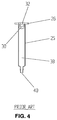
- Fig. 3 is a view of the prior art method of filling syringe 20 with medical paste from tube 10. After flexible piston 30 and evacuation rod 22 are completely removed (see also Fig. 2), distal connector 14 is attached to the proximal end of syringe 20 and intermediate wings 26. The medical paste is squeezed from flexible envelope 12 and into interior bore 38 in the direction of arrow 42. All other elements are as previously descriped.
- Fig. 4 is a sectioned view of the prior art syringe cylinder as completely filled. After tube 10 is emptied (see also Fig. 3), flexible piston 30 is reinserted to seal the proximal end of interior bore 38. The filled syringe cylinder may now be inserted into an injector tool such as is described in more detail below, or in Karl Storz Model 27200 A medical paste injector. Such tools are required to multiply the manual force to overcome the resistance of the thick medical paste.
- Fig. 5 is a sectioned view of a syringe cylinder 60 according to the present invention.
- Cylinder body 68 is made of a disposable polymer. Except for distal port 80 at distal end 66 suitable for a standard Luer coupling, it has a substantially constant diameter along its interior bore or lumen 70. Wing tabs 62 and 64 are located at the proximal end of cylinder body 68.
- Interior bore 70 is provided completely filled with medical adhesive by the supplier.
- the proximal end of interior bore 70 including proximal orifice 74 is sealed with flexible piston 78 which is similar to flexible piston 30 except that it preferably has a flat proximal surface.
- This flat proximal surface permits flexible piston 78 to be moved distally by force supplied from a similarly flat surface.
- proximal surfaces which ar not flat, but also have no means to engage an evacuation rod for pulling flexible piston 78 in a proximal direction. This is important to provide for rapid change of disposable syringe cylinder 60.
- Fig. 6 is a top view of the syringe cylinder 60 of the present invention shown inserted into semi-cylinder 136 of medical paste injector 110 according to the present invention.
- medical adhesive is dispensed from distal port 80 by the force applied to flexible piston 78 from rigid cylinder 154 which is attached via rod 156 to rod 130.
- medical paste is dispensed from distal port 80.
- Fig. 7 is a side view of the medical paste injector 110 employing the present invention.
- the main body 114 of injector 110 is cast of an autoclavable metal having fixed handle 112 configured to fit into the palm of the user's hand.
- a movable handle 120 having surface ridges 122 is configured to fit the user's fingers. Movable handle 120 pivots at axis 124.
- the medical paste is propelled by the work performed by the user as movable handle 120 is pulled toward fixed handle 112 as is discussed in further detail below.
- Pawl 126 is rotatably coupled to movable handle 120 at axis 128. For this reason, as the user pulls movable handle 120 at surface ridges 122 toward fixed handle 112, movable handle 120 pivots at axis 124 and pushes pawl 126 in the opposite direction (i.e. away from fixed handle 112). The forward edge of pawl 126 engages in ratchet edges 132 of ratchet rod 130 to propel rod 130 toward the left of the drawing.
- Ratchet engagement latch 118 is slidably held in jig 116. As rod 130 is advanced, latch 118 engages successive ones of ratchet edges 132 preventing movement of rod 130 to the right. In this way, rod 130 is advanced through rod bearing 142.
- Rod 130 has knob 134 as its proximal end. Knob 134 is attached via threads (not shown) to stop ring 133. Knob 134 performs two separate functions. It is of sufficient diameter as to prevent rod 130 from advancing to the left any further than the engagement of knob 134 with jig 116. Knob 134 also serves as a convenient place to grasp rod 130. This grasping permits the user to manually pull rod 130 to the right, if button 119 attached to latch 118 is simultaneously depressed manually. This operation resets injector 110 for the insertion of a syringe cylinder as explained in further detail below.
- the syringe cylinder (not shown) is inserted into semi-cylinder 136, which is open at the top.
- the distal end of the syringe cylinder is inserted into cylindrical holder 148.
- the distal tip of the syringe cylinder exits via coupling 138 which is tapered at incline 139 from cylindrical holder 148.
- the wing tabs of the syringe cylinder are inserted into slot 140, thus securing the syringe cylinder.
- the medical paste is propelled by the leftward movement of rod 130 through rod bearing 142 and cylinder housing 117.
- Fig. 8 is a front view of injector 110.
- Orifice 144 is the interior lumen of coupling 138. All other referenced elements are as previously described.
- Fig. 9 is a close-up top view of syringe cylinder 60 as positioned within injector 110.
- Syringe cylinder 60 is supplied as prefilled with flexible piston 78 properly positioned.
- Rod 156 is the distal extension of rod 130. As can be seen in the drawing, rod 156 is smooth and has no ratchet edges 132. At the distal end of rod 156 is located cylinder 154. Cylinder 154 pushes on the flexible piston 78 of the syringe cylinder 60. Because flexible piston 78 need only move in a single direction (i.e. distally) during the medical procedure, no piston grip nor corresponding slot in flexible piston 78 is required. All other referenced elements are as previously described.
- Fig. 10 is a side view of injector 110 showing a partial cut-away of main body 114.
- Travel stop pin 180 is fixedly mounted in travel stop pin seat 182. It is the function of travel stop pin 180 to stop the travel of movable handle 120 at point 184 as shown. Limiting the travel of movable handle 120 at this precise point 184 limits the volume to be dispensed to a known small amount. In one preferred embodiment, this corresponds to 0.2 cm3.
- Aural feedback is also provided to the user by coordinating the specific number of ratchet edges 132 passing latch 118 before travel stop pin 180 contacts point 184. In the preferred embodiment, this is precisely three. Therefore, the user hears three clicks of latch 118 acknowledging the maximum travel of one pull on movable handle 120 and the delivery of 0.2 cm3 of medical paste.
- Fig. 11 is top view of an embodiment of injector 110 adapted for use with syringe cylinder 25 of standard syringe 20 shown in Figs. 1 to 3.
- rod 152 having piston grip 150 is located at the distal end of cylinder 154.
- Piston grip 150 is adapted to engage the flexible piston 30 as explained in more detail below. All other referenced elements are as previously described.
- Fig. 12 is a top view of injector 110 shown partially in phantom with syringe cylinder 25 in place.
- the distal end of cylinder 25 is inserted into coupling 138.
- the cylinder body is inserted into semi-cylinder 136.
- Wings 26 are inserted into slot 140.
- Flexible piston 30 slides downwardly to propel the medical paste from inner lumen 38 as cylinder 154 pushes on flexible piston 30 through the proximal orifice of cylinder 25.
- Piston grip 150 is engaged into indentation or slot 32 of flexible piston 30.
- Syringe cylinder 25 is filled by the user with the medicla paste. To do so, flexible piston 30 and the thumb actuator and rod 22, 24 are removed and inner lumen 38 is filled from a tube of sterile medical paste. The thumb actuator 24 and rod 22 (Fig. 2) are discarded and flexible piston 30 is replaced through the proximal orifice of cylinder 25 to occlude the proximal end of inner lumen 38. All referenced elements are as previously described.
- Fig. 13 is a close-up top view of syringe cylinder 25 within injector 110 as partially emptied. All referenced elements are as previously described.
Landscapes
- Health & Medical Sciences (AREA)
- Vascular Medicine (AREA)
- Engineering & Computer Science (AREA)
- Anesthesiology (AREA)
- Biomedical Technology (AREA)
- Heart & Thoracic Surgery (AREA)
- Hematology (AREA)
- Life Sciences & Earth Sciences (AREA)
- Animal Behavior & Ethology (AREA)
- General Health & Medical Sciences (AREA)
- Public Health (AREA)
- Veterinary Medicine (AREA)
- Infusion, Injection, And Reservoir Apparatuses (AREA)
Abstract
A disposable syringe cylinder (60) and a medical paste injector (110) into which the cylinder (60) may be easily inserted. The cylinder (60) is prefilled by the supplier with a medical paste. A flexible piston (78) having a flat proximal surface is inserted by the supplier into the proximal end of the cylinder (60). The piston (78) serves as a seal between the paste and the outer environment. Proximal-to-distal force applied on the piston (78) by the injector (110) propels paste from the cylinder (60). The direction of travel of the flexible piston (78) is only proximal-to-distal, and the disposable syringe cylinder (60) is discarded when empty. The injector (110) includes an injector pump which is manually actuated by a pistol grip. A highly precise ratchet mechanism, along with an accurately positioned stop on the travel of the pistol grip, permits the attending medical personnel to deliver the exact volume of paste required.
Description
- The present invention relates generally to medical devices and procedures, and more particularly, relates to packaging techniques for medical paste and to devices for injecting such paste.
- It has been known for some time to inject a paste or semi-plastic material to reinforce a muscle, such as the urethral sphincter. In this procedure, a catheter is advanced in the urethra to a position adjacent the sphincter muscle. A desired amount of a paste such as PTFE paste is pumped under high pressure to the treatment area near the distal end of the catheter. The outside dimensions of the catheter are established by the necessity to traverse the urethra.
- Medical injection pumps suitable to this task have been available for some time. US-A-4 551 135 describes an injection syringe which provides for the mixing of two different materials at the time of injection.
- A pistol grip style injection syringe is discussed in US-A- 4,276,878. This particular pump employs a flexible piston rod with a series of ball-shaped pistons along its length.
- US-A-4 820 287 shows a thumb operated pump for medical paste. The emphasis of the disclosure is a safety feature for pressure control.
- A thumb-operated Teflon syringe is commercially available from the German Company of Karl Storz as Model 27200 A. This device uses a disposable syringe cylinder to hold the medical paste during the dispensing operation. The disposable syringe cylinder is loaded from a tube of sterile medical paste in accordance with the manufacturer's instructions.
- The Karl Storz device, along with the other prior art devices, lack the ability for consistent and precise injection coupled with one hand operation and ease of replacement of sterile medical paste.
- The present invention overcomes the disadvantages of the prior art in providing a disposable syringe cylinder which is preloaded with sterile medical paste. The disposable syringe cylinder is similar to that commonly found in the art, except that it contains no thumb knob or dispensing rod. The outer cylinder is filled with the medical paste, and a flexible piston is positioned in the proximal end. The flexible piston provides separation of the sterile medical paste from the external environment. The flexible piston requires no engagement means at its proximal surface.
- The present invention further provides for an injector adapted for use with such a disposable syringe cylinder. The syringe is easily inserted into and removed from the injector. The flexible piston of the syringe is employed to propel the medical paste from the syringe and into the catheter. Utilization of the flexible piston in this way preserves the sterile field with a readily disposable element. Except for the disposable syringe cylinder and flexible piston, the remainder of the injector is metal and sterilizable in an autoclave.
- The injector provides for pistol grip operation for single hand use. It employs a highly graduated and accurate ratchet for precise dispensing of the desired volume. The ratchet gives aural feedback to indicate the dispensed volume. A special stop rod limits the travel of the pistol grip such that a small (e.g. 0.2 cm³) volume is precisely delivered with each manual stroke.
- The distal end of the syringe is coupled to the proximal end of the catheter with a standard Luer coupling. The catheter is of an appropriate length and diameter for use in the urethra. The catheter must have sufficient strength to accommodate the relatively high pressures associated with dispensing of the semi-plastic material.
- Other objects of the present invention and many of the attendant advantages of the present invention will be readily appreciated as the same becomes better understood by reference to the following detailed description when considered in connection with the accompanying drawings, in which like reference numerals designate like parts throughout the figures thereof and wherein:
- Fig. 1
- is a plan view of the components of the prior art system;
- Fig. 2
- is an exploded view of the prior art syringe cylinder;
- Fig. 3
- is an operational view of the prior art method of filling the syringe cylinder;
- Fig. 4
- is a sectioned view of the completely filled prior art syringe cylinder;
- Fig. 5
- is a plan view of a syringe cylinder employing the present invention;
- Fig. 6
- is a top view of a medical paste injector employing a syringe cylinder according to the present invention;
- Fig. 7
- is a side view of the main body of an injector incorporating the present invention and adapted for use with a syringe cylinder employing the present invention;
- Fig. 8
- is a front end view of the injector assembly;
- Fig. 9
- is an enlarged view of the distal portion of the arrangement of Fig. 6 including the medical paste injector and syringe cylinder according to the present invention;
- Fig. 10
- is a side view of the injector cut-away showing the stop rod;
- Fig. 11
- is a view of an alternative embodiment of the injector;
- Fig. 12
- is a top view of the injector assembly of Fig. 11 after insertion of a prior art syringe cylinder; and
- Fig. 13
- is a close-up view of the injector and syringe cylinder of Fig. 12 with the disposable syringe cylinder being illustrated in partial phantom showing the dispensing operation.
- Fig. 1 is a plan view of the components of the prior art system.
Tube 10 contains the sterile medical paste to be injected using an injection tool. Typically this may be a PTFE paste available from the assignee of the present invention.Tube 10 contains standardflexible envelope 12 havingdistal connector 14 andevacuation port 16. -
Syringe 20 is a standard disposable syringe. It typically has amain cylinder 25 of a polymer. Interior bore 38 has a constant diameter from proximal to distal end except fordistal port 40. Ordinarilydistal port 40 is coupled using a standard Luer coupling to a hollow stainless steel needle (not shown). When used to dispense medical paste,distal port 40 is typically coupled to a catheter for remote placement. -
Flexible piston 30 is typically an element of generally cylindrical shape of soft rubber. The diameter offlexible piston 30 is chosen to snugly fitinterior bore 38. At the proximal end offlexible piston 30 is located acentral indentation 32. It is structured to have a smaller proximal bore and a relatively larger more distal bore. However,central indentation 32 does not extend through the distal surface offlexible piston 30. -
Central indentation 32 offlexible piston 30 is press fit on tocoupling point 36 ofevacuation rod 22. This permitsevacuation rod 22 to moveflexible piston 30 proximally and distally withininterior bore 38.Evacuation rod 22 has a generally cruciform shape forstrength having rib 28 and three other similar ribs.Thumb knob 24 is appended to the proximal end ofevacuation rod 22 for ease of use by the operator.Wings 26 provide for ease in grasping the proximal end ofsyringe 20. - In normal use, interior bore 38 is vacuum filled with a liquid by manually pulling thumb know 24 and hence
flexible piston 30 proximally. The liquid is then dispensed by pushingthumb knob 24 distally. The index and middle finger of theoperator grasp wings 26 to permit ease in exerting the desired force. However, the medical paste to be dispensed is too thick to be dispensed in this manner. - Fig. 2 is an exploded view of
prior art syringe 20. All referenced elements are as previously described. - Fig. 3 is a view of the prior art method of filling
syringe 20 with medical paste fromtube 10. Afterflexible piston 30 andevacuation rod 22 are completely removed (see also Fig. 2),distal connector 14 is attached to the proximal end ofsyringe 20 andintermediate wings 26. The medical paste is squeezed fromflexible envelope 12 and into interior bore 38 in the direction ofarrow 42. All other elements are as previously descriped. - Fig. 4 is a sectioned view of the prior art syringe cylinder as completely filled. After
tube 10 is emptied (see also Fig. 3),flexible piston 30 is reinserted to seal the proximal end ofinterior bore 38. The filled syringe cylinder may now be inserted into an injector tool such as is described in more detail below, or in Karl Storz Model 27200 A medical paste injector. Such tools are required to multiply the manual force to overcome the resistance of the thick medical paste. - Fig. 5 is a sectioned view of a
syringe cylinder 60 according to the present invention.Cylinder body 68 is made of a disposable polymer. Except fordistal port 80 atdistal end 66 suitable for a standard Luer coupling, it has a substantially constant diameter along its interior bore orlumen 70.Wing tabs cylinder body 68. - Interior bore 70 is provided completely filled with medical adhesive by the supplier. The proximal end of interior bore 70 including
proximal orifice 74 is sealed withflexible piston 78 which is similar toflexible piston 30 except that it preferably has a flat proximal surface. This flat proximal surface permitsflexible piston 78 to be moved distally by force supplied from a similarly flat surface. Embodiments are envisioned with proximal surfaces which ar not flat, but also have no means to engage an evacuation rod for pullingflexible piston 78 in a proximal direction. This is important to provide for rapid change ofdisposable syringe cylinder 60. - Fig. 6 is a top view of the
syringe cylinder 60 of the present invention shown inserted intosemi-cylinder 136 ofmedical paste injector 110 according to the present invention. In operation, medical adhesive is dispensed fromdistal port 80 by the force applied toflexible piston 78 fromrigid cylinder 154 which is attached viarod 156 torod 130. Asrod 130 is advanced, medical paste is dispensed fromdistal port 80. - Fig. 7 is a side view of the
medical paste injector 110 employing the present invention. Themain body 114 ofinjector 110 is cast of an autoclavable metal having fixed handle 112 configured to fit into the palm of the user's hand. Amovable handle 120 havingsurface ridges 122 is configured to fit the user's fingers.Movable handle 120 pivots ataxis 124. The medical paste is propelled by the work performed by the user asmovable handle 120 is pulled toward fixedhandle 112 as is discussed in further detail below. -
Pawl 126 is rotatably coupled tomovable handle 120 ataxis 128. For this reason, as the user pullsmovable handle 120 atsurface ridges 122 toward fixedhandle 112,movable handle 120 pivots ataxis 124 and pushespawl 126 in the opposite direction (i.e. away from fixed handle 112). The forward edge ofpawl 126 engages in ratchet edges 132 ofratchet rod 130 to propelrod 130 toward the left of the drawing.Ratchet engagement latch 118 is slidably held injig 116. Asrod 130 is advanced,latch 118 engages successive ones of ratchet edges 132 preventing movement ofrod 130 to the right. In this way,rod 130 is advanced throughrod bearing 142. -
Rod 130 hasknob 134 as its proximal end.Knob 134 is attached via threads (not shown) to stopring 133.Knob 134 performs two separate functions. It is of sufficient diameter as to preventrod 130 from advancing to the left any further than the engagement ofknob 134 withjig 116.Knob 134 also serves as a convenient place to grasprod 130. This grasping permits the user to manually pullrod 130 to the right, ifbutton 119 attached to latch 118 is simultaneously depressed manually. This operation resetsinjector 110 for the insertion of a syringe cylinder as explained in further detail below. - The syringe cylinder (not shown) is inserted into
semi-cylinder 136, which is open at the top. The distal end of the syringe cylinder is inserted intocylindrical holder 148. The distal tip of the syringe cylinder exits viacoupling 138 which is tapered atincline 139 fromcylindrical holder 148. The wing tabs of the syringe cylinder are inserted intoslot 140, thus securing the syringe cylinder. The medical paste is propelled by the leftward movement ofrod 130 through rod bearing 142 andcylinder housing 117. - Fig. 8 is a front view of
injector 110.Orifice 144 is the interior lumen ofcoupling 138. All other referenced elements are as previously described. - Fig. 9 is a close-up top view of
syringe cylinder 60 as positioned withininjector 110.Syringe cylinder 60 is supplied as prefilled withflexible piston 78 properly positioned.Rod 156 is the distal extension ofrod 130. As can be seen in the drawing,rod 156 is smooth and has no ratchet edges 132. At the distal end ofrod 156 is locatedcylinder 154.Cylinder 154 pushes on theflexible piston 78 of thesyringe cylinder 60. Becauseflexible piston 78 need only move in a single direction (i.e. distally) during the medical procedure, no piston grip nor corresponding slot inflexible piston 78 is required. All other referenced elements are as previously described. - Fig. 10 is a side view of
injector 110 showing a partial cut-away ofmain body 114.Travel stop pin 180 is fixedly mounted in travelstop pin seat 182. It is the function oftravel stop pin 180 to stop the travel ofmovable handle 120 atpoint 184 as shown. Limiting the travel ofmovable handle 120 at thisprecise point 184 limits the volume to be dispensed to a known small amount. In one preferred embodiment, this corresponds to 0.2 cm³. - Aural feedback is also provided to the user by coordinating the specific number of ratchet edges 132 passing
latch 118 beforetravel stop pin 180contacts point 184. In the preferred embodiment, this is precisely three. Therefore, the user hears three clicks oflatch 118 acknowledging the maximum travel of one pull onmovable handle 120 and the delivery of 0.2 cm³ of medical paste. - Fig. 11 is top view of an embodiment of
injector 110 adapted for use withsyringe cylinder 25 ofstandard syringe 20 shown in Figs. 1 to 3. In thisembodiment rod 152 havingpiston grip 150 is located at the distal end ofcylinder 154.Piston grip 150 is adapted to engage theflexible piston 30 as explained in more detail below. All other referenced elements are as previously described. - Fig. 12 is a top view of
injector 110 shown partially in phantom withsyringe cylinder 25 in place. The distal end ofcylinder 25 is inserted intocoupling 138. The cylinder body is inserted intosemi-cylinder 136.Wings 26 are inserted intoslot 140.Flexible piston 30 slides downwardly to propel the medical paste frominner lumen 38 ascylinder 154 pushes onflexible piston 30 through the proximal orifice ofcylinder 25.Piston grip 150 is engaged into indentation or slot 32 offlexible piston 30. -
Syringe cylinder 25 is filled by the user with the medicla paste. To do so,flexible piston 30 and the thumb actuator androd inner lumen 38 is filled from a tube of sterile medical paste. Thethumb actuator 24 and rod 22 (Fig. 2) are discarded andflexible piston 30 is replaced through the proximal orifice ofcylinder 25 to occlude the proximal end ofinner lumen 38. All referenced elements are as previously described. - Fig. 13 is a close-up top view of
syringe cylinder 25 withininjector 110 as partially emptied. All referenced elements are as previously described. - Having thus described the preferred embodiments of the present invention, those of skill in the art will readily appreciate the many other embodiments which can be employed within the scope of the claims hereto attached.
Claims (4)
- An apparatus comprising:(a) a syringe cylinder (60) having a substantially constant interior diameter;(b) a distal port (74) at a distal end of said syringe cylinder;(c) a medical paste filling said syringe cylinder; and(d) a flexible piston (72) having a substantially flat proximal surface frictionally engaged within said substantial constant interior diameter.
- A method of supplying a medical paste comprising:(a) filling a syringe cylinder (60) with said medical paste; and(b) securing a proximal end of said syringe cylinder with a flexible piston (72) having a substantially flat proximal surface.
- A medical paste injector (110) comprising:(a) a main body (114);(b) a fixed handle (112) attached to said main body;(c) a movable handle (120) rotatably attached to said main body (114);(d) means (60) removably attached to said main body (114) for holding said medical paste;(e) means (126, 130, 154, 156) attached to said movable handle (120) and said main body (114) such that movement of said movable handle (120) relative to said fixed handle (112) dispenses said medical paste from said holding means (60); and(f) means (180, 182) attached to said main body (114) for limiting said dispensing of said medical paste to a fixed volume.
- An injector according to claim 3 further comprising means (118, 132) coupled to said main body (114) for providing an aural indication of said fixed volume.
Applications Claiming Priority (4)
| Application Number | Priority Date | Filing Date | Title |
|---|---|---|---|
| US57711690A | 1990-09-04 | 1990-09-04 | |
| US577116 | 1990-09-04 | ||
| US58235390A | 1990-09-14 | 1990-09-14 | |
| US582353 | 1990-09-14 |
Publications (1)
| Publication Number | Publication Date |
|---|---|
| EP0474218A1 true EP0474218A1 (en) | 1992-03-11 |
Family
ID=27077156
Family Applications (1)
| Application Number | Title | Priority Date | Filing Date |
|---|---|---|---|
| EP91114947A Withdrawn EP0474218A1 (en) | 1990-09-04 | 1991-09-04 | Medical paste syringe, filling method and paste injecting device |
Country Status (2)
| Country | Link |
|---|---|
| EP (1) | EP0474218A1 (en) |
| AU (1) | AU8362391A (en) |
Cited By (9)
| Publication number | Priority date | Publication date | Assignee | Title |
|---|---|---|---|---|
| WO1999008735A3 (en) * | 1997-08-14 | 1999-04-15 | Nycomed Imaging As | Hand-held manual injector |
| WO2004062713A1 (en) * | 2003-01-16 | 2004-07-29 | Konica Minolta Medical & Graphic, Inc. | Injection auxiliary tool |
| US7988677B2 (en) | 2001-05-24 | 2011-08-02 | Covidien Ag | Hand-held, hand-operated power syringe and methods |
| US8539644B2 (en) | 2006-10-24 | 2013-09-24 | Mallinckrodt Llc | Hinge assembly for an injector |
| US8672893B2 (en) | 2007-10-23 | 2014-03-18 | Control Medical Technology, Llc | Syringe with rotatable element, aspiration systems including the syringe, and associated methods |
| US10058656B2 (en) | 2006-10-24 | 2018-08-28 | Pmt Partners, Llc | Syringe with rotatable element, systems including the syringe, and associated methods |
| CN112535778A (en) * | 2020-12-08 | 2021-03-23 | 中国医学科学院整形外科医院 | Boosting cap and injector |
| US10987469B2 (en) | 2014-09-25 | 2021-04-27 | Pmt Partners, Llc | Rotatable finger loop for syringe, syringe configured to receive the rotatable finger loop and associated methods |
| US11191931B2 (en) | 2007-10-01 | 2021-12-07 | Pmt Partners, Llc | Methods for manually injecting/aspirating fluids through small diameter catheters and needles and manual injection/aspiration systems including small diameter catheters and needles |
Citations (6)
| Publication number | Priority date | Publication date | Assignee | Title |
|---|---|---|---|---|
| US3517668A (en) * | 1967-10-16 | 1970-06-30 | Bio Neering Inc | Multiple dosage veterinary injection gun |
| GB2142245A (en) * | 1981-10-26 | 1985-01-16 | Dr William B Dragan | Multi-purpose dental syringe |
| US4551135A (en) * | 1981-06-22 | 1985-11-05 | Sterling Drug Inc. | Syringe for extrusion of semi-plastic material |
| US4710172A (en) * | 1986-11-24 | 1987-12-01 | John Jacklich | High pressure syringe with pressure indicator |
| WO1988000843A1 (en) * | 1986-07-30 | 1988-02-11 | Mate Robert | Self-injection device, with doser for throw-away medical syringes |
| FR2630330A1 (en) * | 1988-04-22 | 1989-10-27 | Hoepfner Jean Paul | Syringe for injecting medicinal or other materials contained in a carpule |
-
1991
- 1991-09-04 EP EP91114947A patent/EP0474218A1/en not_active Withdrawn
- 1991-09-04 AU AU83623/91A patent/AU8362391A/en not_active Abandoned
Patent Citations (6)
| Publication number | Priority date | Publication date | Assignee | Title |
|---|---|---|---|---|
| US3517668A (en) * | 1967-10-16 | 1970-06-30 | Bio Neering Inc | Multiple dosage veterinary injection gun |
| US4551135A (en) * | 1981-06-22 | 1985-11-05 | Sterling Drug Inc. | Syringe for extrusion of semi-plastic material |
| GB2142245A (en) * | 1981-10-26 | 1985-01-16 | Dr William B Dragan | Multi-purpose dental syringe |
| WO1988000843A1 (en) * | 1986-07-30 | 1988-02-11 | Mate Robert | Self-injection device, with doser for throw-away medical syringes |
| US4710172A (en) * | 1986-11-24 | 1987-12-01 | John Jacklich | High pressure syringe with pressure indicator |
| FR2630330A1 (en) * | 1988-04-22 | 1989-10-27 | Hoepfner Jean Paul | Syringe for injecting medicinal or other materials contained in a carpule |
Cited By (12)
| Publication number | Priority date | Publication date | Assignee | Title |
|---|---|---|---|---|
| WO1999008735A3 (en) * | 1997-08-14 | 1999-04-15 | Nycomed Imaging As | Hand-held manual injector |
| US7988677B2 (en) | 2001-05-24 | 2011-08-02 | Covidien Ag | Hand-held, hand-operated power syringe and methods |
| US8672900B2 (en) | 2001-05-24 | 2014-03-18 | Mallinckrodt Llc | Hand-held, hand-operated power syringe and methods |
| WO2004062713A1 (en) * | 2003-01-16 | 2004-07-29 | Konica Minolta Medical & Graphic, Inc. | Injection auxiliary tool |
| US8539644B2 (en) | 2006-10-24 | 2013-09-24 | Mallinckrodt Llc | Hinge assembly for an injector |
| US10058656B2 (en) | 2006-10-24 | 2018-08-28 | Pmt Partners, Llc | Syringe with rotatable element, systems including the syringe, and associated methods |
| US10207057B2 (en) | 2006-10-24 | 2019-02-19 | Control Medical Technology, Llc | Syringe with rotatable element, systems including the syringe, and associated methods |
| US11071827B2 (en) | 2006-10-24 | 2021-07-27 | Pmt Partners, Llc | Syringe with rotatable element, systems including the syringe, and associated methods |
| US11191931B2 (en) | 2007-10-01 | 2021-12-07 | Pmt Partners, Llc | Methods for manually injecting/aspirating fluids through small diameter catheters and needles and manual injection/aspiration systems including small diameter catheters and needles |
| US8672893B2 (en) | 2007-10-23 | 2014-03-18 | Control Medical Technology, Llc | Syringe with rotatable element, aspiration systems including the syringe, and associated methods |
| US10987469B2 (en) | 2014-09-25 | 2021-04-27 | Pmt Partners, Llc | Rotatable finger loop for syringe, syringe configured to receive the rotatable finger loop and associated methods |
| CN112535778A (en) * | 2020-12-08 | 2021-03-23 | 中国医学科学院整形外科医院 | Boosting cap and injector |
Also Published As
| Publication number | Publication date |
|---|---|
| AU8362391A (en) | 1992-03-12 |
Similar Documents
| Publication | Publication Date | Title |
|---|---|---|
| EP0810890B1 (en) | Electronic syringe | |
| CA2236049C (en) | Syringe with detachable syringe barrel | |
| EP1351732B2 (en) | Automatic injection device with reset feature | |
| US6616634B2 (en) | Ergonomic syringe | |
| EP0080793B1 (en) | A dental syringe | |
| US8672900B2 (en) | Hand-held, hand-operated power syringe and methods | |
| US5830194A (en) | Power syringe | |
| US5807340A (en) | Self refilling I.V. syringe | |
| AU2001261790B2 (en) | Fluid material dispensing syringe | |
| US7022112B2 (en) | High pressure syringe | |
| US4925449A (en) | Manually driven syringe | |
| CZ144796A3 (en) | Portable hand-held mechanical injector | |
| EA003077B1 (en) | Injector device and method for its operation | |
| HU215073B (en) | Portable powered, manual injection device | |
| AU2001261790A1 (en) | Fluid material dispensing syringe | |
| WO1989009071A1 (en) | Disposable control syringe | |
| EP0474218A1 (en) | Medical paste syringe, filling method and paste injecting device | |
| CN215018481U (en) | Thrombolysis system | |
| JPH0584295A (en) | Medical pasta syringe | |
| AU749369B2 (en) | Electronic syringe | |
| IL278534A (en) | A syringe aid device | |
| JPH0592037A (en) | Therapeutic paste injector and its filling method | |
| WO1999047193A1 (en) | High pressure syringe |
Legal Events
| Date | Code | Title | Description |
|---|---|---|---|
| PUAI | Public reference made under article 153(3) epc to a published international application that has entered the european phase |
Free format text: ORIGINAL CODE: 0009012 |
|
| AK | Designated contracting states |
Kind code of ref document: A1 Designated state(s): BE DE ES FR GB IT NL |
|
| STAA | Information on the status of an ep patent application or granted ep patent |
Free format text: STATUS: THE APPLICATION IS DEEMED TO BE WITHDRAWN |
|
| 18D | Application deemed to be withdrawn |
Effective date: 19920912 |