EP0473283B1 - Reinforcements for flexible strips - Google Patents
Reinforcements for flexible strips Download PDFInfo
- Publication number
- EP0473283B1 EP0473283B1 EP91306722A EP91306722A EP0473283B1 EP 0473283 B1 EP0473283 B1 EP 0473283B1 EP 91306722 A EP91306722 A EP 91306722A EP 91306722 A EP91306722 A EP 91306722A EP 0473283 B1 EP0473283 B1 EP 0473283B1
- Authority
- EP
- European Patent Office
- Prior art keywords
- slots
- carrier
- channel
- side wall
- wall
- Prior art date
- Legal status (The legal status is an assumption and is not a legal conclusion. Google has not performed a legal analysis and makes no representation as to the accuracy of the status listed.)
- Expired - Lifetime
Links
- 230000002787 reinforcement Effects 0.000 title description 2
- 239000000463 material Substances 0.000 claims description 7
- 230000003014 reinforcing effect Effects 0.000 claims description 2
- 238000007789 sealing Methods 0.000 description 17
- 239000002184 metal Substances 0.000 description 8
- 238000000034 method Methods 0.000 description 4
- 238000001125 extrusion Methods 0.000 description 3
- 238000005452 bending Methods 0.000 description 2
- 239000000969 carrier Substances 0.000 description 2
- 238000004519 manufacturing process Methods 0.000 description 2
- 239000000853 adhesive Substances 0.000 description 1
- 230000001070 adhesive effect Effects 0.000 description 1
- 230000001413 cellular effect Effects 0.000 description 1
- 238000010276 construction Methods 0.000 description 1
- 230000000694 effects Effects 0.000 description 1
- 239000003000 extruded plastic Substances 0.000 description 1
- 238000010348 incorporation Methods 0.000 description 1
- 239000004033 plastic Substances 0.000 description 1
- 229920003023 plastic Polymers 0.000 description 1
- 229920002994 synthetic fiber Polymers 0.000 description 1
- 238000009966 trimming Methods 0.000 description 1
Images


Classifications
-
- B—PERFORMING OPERATIONS; TRANSPORTING
- B60—VEHICLES IN GENERAL
- B60J—WINDOWS, WINDSCREENS, NON-FIXED ROOFS, DOORS, OR SIMILAR DEVICES FOR VEHICLES; REMOVABLE EXTERNAL PROTECTIVE COVERINGS SPECIALLY ADAPTED FOR VEHICLES
- B60J10/00—Sealing arrangements
- B60J10/20—Sealing arrangements characterised by the shape
- B60J10/24—Sealing arrangements characterised by the shape having tubular parts
-
- B—PERFORMING OPERATIONS; TRANSPORTING
- B60—VEHICLES IN GENERAL
- B60J—WINDOWS, WINDSCREENS, NON-FIXED ROOFS, DOORS, OR SIMILAR DEVICES FOR VEHICLES; REMOVABLE EXTERNAL PROTECTIVE COVERINGS SPECIALLY ADAPTED FOR VEHICLES
- B60J10/00—Sealing arrangements
- B60J10/15—Sealing arrangements characterised by the material
- B60J10/18—Sealing arrangements characterised by the material provided with reinforcements or inserts
Definitions
- the invention relates to a generally channel-shaped carrier for reinforcing a channel-shaped flexible strip, comprising in each side wall of the channel a respective series of slots arranged side-by-side along the length of the carrier, the slots being of two different types, each slot through one of the side walls being displaced along the length of the carrier with respect to a respective one of the slots of the same type in the other side wall of the channel.
- Such a carrier is known from GB-A-2 181 698.
- the slots of one type are all arranged along one of the side walls of the carrier and the slots of the other type are all arranged along the other side wall of the carrier, and each slot opens into the free edge of the respective side wall.
- the slots in the two side walls are of respectively different types, they can be configured to render the carrier more easily bendable in one direction (with respect to an axis normal to the base of the channel) than in the opposite direction.
- This is advantageous when the carrier is incorporated into sealing strips for particular sealing applications (such as for sealing around luggage compartment openings in motor vehicle bodies).
- this asymetric bendability of the carrier is disadvantageous in certain other applications.
- each of the slots opens into a respective one of the free edges of the channel
- the carrier is significantly flexible; this may be disadvantageous in certain applications where a semi-rigid form of carrier is more suitable because of its ability to retain or substantially retain a particular bent configuration.
- each of the two series of slots includes slots of both said types alternating with each other along the respective side wall, in that each of the slots of one said type is a short slot open to the longitudinally extending free edge of the respective wall and extends in that wall from that edge to terminate in the same wall, and in that each of the slots of the other said type is a respective closed long slot extending from a point within the respective side wall to terminate at a point in the base of the channel.
- the sealing strip comprises a channel-shaped gripping part 4 and a tubular sealing part 5.
- the gripping part 4 is made of channel-shaped extruded plastics material 6 which is extruded over a channel-shaped metal reinforcement or carrier 8 to be described in more detail below.
- the extrusion process may use a cross-head extruder.
- a flexible substantially inextensible tape 9 made of synthetic material may be embedded within the plastics material 6 during the extrusion process.
- the extrusion process is such as to form gripping lips 10 on the inside of the channel and facing each other.
- the sealing part 5 is made of extruded rubber material, preferably of cellular construction and is of hollow tubular form. It is secured to the side of the gripping part 4 as by adhesive.
- the gripping part 4 is used to secure the sealing strip on a flange surrounding a door or similar opening in a motor vehicle body, the channel of the part 4 embracing the flange so that the lips 10 make tight frictional engagement with the flange and support the sealing part 5 to run around the periphery of the door opening so as to be sealingly compressed by the closing door.
- the gripping action of the gripping part 4 is enhanced by the resilience of the metal carrier 8.
- the tape 9 helps to prevent stretching of the strip, particularly when it is being applied to the flange.
- the form of the strip illustrated in Figure 1 is merely by way of example and may be varied in many different ways. For example, there may be more or fewer lips 10 and they may have different shapes.
- the extruded material of the gripping part 4 and the sealing part 5 may be integral and extruded in a single operation; for example, both may be made of extruded rubber, which again is extruded over the metal carrier 8 using a cross-head extruder.
- Figure 2 shows a slightly different form of sealing strip mounted on a flange 12. Parts in Figure 2 corresponding to parts in Figure 1 are similarly referenced. In this case, the extruded material of the gripping part 4 is integrally extruded with the extruded material of the sealing part 5.
- the metal carrier 8 needs to be sufficiently resilient to enable it to assist in firmly retaining the gripping part 4 on the flange. In addition, however, it must be sufficiently flexible to enable the strip to be bent to follow curves in the flange. For example, the door surround will contain bends or corners, often of quite small radius and the carrier must permit the strip to be bent accordingly.
- such pre-formed lengths of sealing strip are in the form of closed rings with appropriately pre-formed bends or corners and which are delivered to the vehicle manufacturer ready for assembly (manually or by robot) onto the appropriate flange.
- the metal carrier 8 has to be sufficiently flexible to enable it to be bent to match the bends or corners but sufficiently rigid to maintain the bends or corners thereafter.
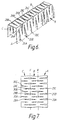
- Figure 3 shows a perspective view of one form of the metal carrier. As shown, it is of channel-shaped configuration and provided with a series of side-by-side slots. Each slot is either a long slot or a short slot. Side wall A of the channel is formed with short slots 20A,20B,20C... . Each of these slots opens into a narrow slit 22A,22B,22C..., the slits being formed in and through a narrow marginal portion 24.
- the short slots 20A,20B,20C terminate approximately three quarters of the distance up the side wall A.
- a respective long slot 26A,26B,26C... is formed between each pair of short slots 20A,20B,20C..., each such long slot 26A,26B,26C commencing about midway up the side wall A and extending into the base B and terminating more than half way across the base B.
- the side wall C is formed with short slots (not visible in Figure 3) corresponding to the short slots 20A,20B and 20C.
- the short slots in the side wall C are staggered in relation to the short slots 20A,20B,20C..., each of the short slots in the side wall C being positioned in alignment with a respective one of the long slots 26A,26B,26C.
- Each of the short slots in the side wall C is in alignment with a respective slit similar to the slits 22A,22B,22C... and which extends in and through a marginal portion 27.
- each of the long slots 28A,28B,28C commences slightly below the middle of the side wall C and extends (as shown) into the base B and terminates more than half way across the base B. Furthermore, each of the long slots 28A,28B,28C... is in alignment with a respective one of the short slots 20A,20B,20C... .
- Figure 4 shows a plan view of the carrier 8 of Figure 3 but during a stage in its manufacture when it is in a flat form, and items in Figure 4 corresponding to those in Figure 3 are similarly referenced.
- the short slots in the side wall C which are not visible in Figure 3, are referenced 30A,30B,30C... and their slits corresponding to the slits 22A,22B,22C are referenced 32A,32B,32C... .
- Lines X and Y in Figure 4 show the lines along which the flat carrier is subsequently bent to form the channel-shape shown in Figure 3.
- Figure 5 shows at A a side view of the side wall A (taken from outside the channel) and of course shows the slots 20A,20B,20C..., the slits 22A,22B,22C... and part of the long slots 26A,26B,26C, and at C shows the corresponding view of the side wall C (viewed in the same direction as side wall A - that is, from the inside of the channel) with its short slots 30A,30B,30C... and its slits 32A,32B,32C..., together with part of the long slots 28A,28B,28C.
- the side walls A and C shown in Figure 5 are shown in the exact relationship which they have in the carrier, and this emphasises how the slots through one of the side walls are offset, along the length of the carrier, in relation to the slots through the other side wall. Therefore, when the strip, with the carrier embedded within it, is bent to follow a curve or corner, such bending will be resisted by the asymetric arrangement of the slots in the two side walls.
- the manner in which the configuration of the carrier changes at such a bend is shown at P and Q in Figure 5.
- a slot 20N opens up in side wall A (as do its neighbouring similar slots).
- Slot 20N is not positioned in alignment with a similarly opening short slot in side C but with part of a long slot 28N - which does not open up during the bending operation. Because of this asymetric arrangement of slots, a certain amount of strain is created in the metal when bends occur. This strain has the effect of making the carrier semi-rigid in form. In other words, although it may be bent to follow curves or corners, once bent it retains its bent shape. It is thus able to preserve a predetermined configuration for a closed ring of sealing strip.
- the semi-rigidity of the carrier also comes into operation if the carrier (embedded in a strip) is bent about an axis passing vertically through the inverted base C of the carrier (so as to follow sinuous variations in the path of the flange).
- the tape 9 may not be necessary in order to prevent stretching. Furthermore, the characteristics of the carrier help it to resist stretching during the process in which it is passed through the extruder and also ensure that the strip in which it is embedded has very good clamping efficiency on the mounting flange.
- Figures 6 and 7 correspond to Figures 3 and 4 and show a modified design for the carrier in which items corresponding to those in Figures 3 and 4 are correspondingly referenced.
- the narrow slits 22A,22B,22C... and 32A,32B,32C... are omitted.
Landscapes
- Engineering & Computer Science (AREA)
- Mechanical Engineering (AREA)
- Seal Device For Vehicle (AREA)
- Containers Opened By Tearing Frangible Portions (AREA)
Description
- The invention relates to a generally channel-shaped carrier for reinforcing a channel-shaped flexible strip, comprising in each side wall of the channel a respective series of slots arranged side-by-side along the length of the carrier, the slots being of two different types, each slot through one of the side walls being displaced along the length of the carrier with respect to a respective one of the slots of the same type in the other side wall of the channel.
- Such a carrier is known from GB-A-2 181 698. In this carrier the slots of one type are all arranged along one of the side walls of the carrier and the slots of the other type are all arranged along the other side wall of the carrier, and each slot opens into the free edge of the respective side wall. Because the slots in the two side walls are of respectively different types, they can be configured to render the carrier more easily bendable in one direction (with respect to an axis normal to the base of the channel) than in the opposite direction. This is advantageous when the carrier is incorporated into sealing strips for particular sealing applications (such as for sealing around luggage compartment openings in motor vehicle bodies). However, this asymetric bendability of the carrier is disadvantageous in certain other applications. Furthermore, because each of the slots opens into a respective one of the free edges of the channel, the carrier is significantly flexible; this may be disadvantageous in certain applications where a semi-rigid form of carrier is more suitable because of its ability to retain or substantially retain a particular bent configuration. These are the problems which the invention aims to overcome.
- Accordingly, the carrier as first set forth above is characterised in that each of the two series of slots includes slots of both said types alternating with each other along the respective side wall, in that each of the slots of one said type is a short slot open to the longitudinally extending free edge of the respective wall and extends in that wall from that edge to terminate in the same wall, and in that each of the slots of the other said type is a respective closed long slot extending from a point within the respective side wall to terminate at a point in the base of the channel.
- Metal carriers embodying the invention, and for incorporation in flexible trimming, finishing and sealing strips, will now be described, by way of example only, with reference to the accompanying diagrammatic drawings in which:
- Figure 1 is a perspective sectioned view of one of the sealing strips;
- Figure 2 is a cross-sectional view of a slightly different form of sealing strip, mounted on a flange;
- Figure 3 is a perspective view of one of the carriers;
- Figure 4 is a view of the carrier of Figure 3 at a stage during its manufacture;
- Figure 5 shows side views of opposite sides of the carrier of Figure 3, illustrating how the two sides are aligned with each other in the carrier; and
- Figures 6 and 7 correspond to Figures 3 and 4 but show a modified form of the carrier.
- As shown in Figure 1, the sealing strip comprises a channel-shaped gripping part 4 and a
tubular sealing part 5. The gripping part 4 is made of channel-shaped extruded plastics material 6 which is extruded over a channel-shaped metal reinforcement or carrier 8 to be described in more detail below. The extrusion process may use a cross-head extruder. A flexible substantially inextensible tape 9 made of synthetic material may be embedded within the plastics material 6 during the extrusion process. The extrusion process is such as to form grippinglips 10 on the inside of the channel and facing each other. - The sealing
part 5 is made of extruded rubber material, preferably of cellular construction and is of hollow tubular form. It is secured to the side of the gripping part 4 as by adhesive. - In use, the gripping part 4 is used to secure the sealing strip on a flange surrounding a door or similar opening in a motor vehicle body, the channel of the part 4 embracing the flange so that the
lips 10 make tight frictional engagement with the flange and support the sealingpart 5 to run around the periphery of the door opening so as to be sealingly compressed by the closing door. The gripping action of the gripping part 4 is enhanced by the resilience of the metal carrier 8. - The tape 9 helps to prevent stretching of the strip, particularly when it is being applied to the flange.
- The form of the strip illustrated in Figure 1 is merely by way of example and may be varied in many different ways. For example, there may be more or
fewer lips 10 and they may have different shapes. The extruded material of the gripping part 4 and the sealingpart 5 may be integral and extruded in a single operation; for example, both may be made of extruded rubber, which again is extruded over the metal carrier 8 using a cross-head extruder. - Figure 2 shows a slightly different form of sealing strip mounted on a
flange 12. Parts in Figure 2 corresponding to parts in Figure 1 are similarly referenced. In this case, the extruded material of the gripping part 4 is integrally extruded with the extruded material of the sealingpart 5. - In each case, the metal carrier 8 needs to be sufficiently resilient to enable it to assist in firmly retaining the gripping part 4 on the flange. In addition, however, it must be sufficiently flexible to enable the strip to be bent to follow curves in the flange. For example, the door surround will contain bends or corners, often of quite small radius and the carrier must permit the strip to be bent accordingly. In addition, it is desirable in many applications to produce lengths of sealing strip to suit particular door openings, that is, pre-formed with bends and curves in the appropriate places to match the door opening. Preferably, such pre-formed lengths of sealing strip are in the form of closed rings with appropriately pre-formed bends or corners and which are delivered to the vehicle manufacturer ready for assembly (manually or by robot) onto the appropriate flange. To meet such a requirement, the metal carrier 8 has to be sufficiently flexible to enable it to be bent to match the bends or corners but sufficiently rigid to maintain the bends or corners thereafter.
- Figure 3 shows a perspective view of one form of the metal carrier. As shown, it is of channel-shaped configuration and provided with a series of side-by-side slots. Each slot is either a long slot or a short slot. Side wall A of the channel is formed with
short slots narrow slit marginal portion 24. Theshort slots long slot short slots long slot - The side wall C is formed with short slots (not visible in Figure 3) corresponding to the
short slots short slots long slots - Each of the short slots in the side wall C is in alignment with a respective slit similar to the
slits marginal portion 27. - Finally, further
long slots long slots long slots long slots short slots - Figure 4 shows a plan view of the carrier 8 of Figure 3 but during a stage in its manufacture when it is in a flat form, and items in Figure 4 corresponding to those in Figure 3 are similarly referenced. In Figure 4, the short slots in the side wall C, which are not visible in Figure 3, are referenced 30A,30B,30C... and their slits corresponding to the
slits - It will be apparent that the form of carrier illustrated is such that, although the slots and slits formed through each of the side walls A and C are configured similarly, the slots in one side wall are offset in relation to those in the other wall. Thus, Figure 5 shows at A a side view of the side wall A (taken from outside the channel) and of course shows the
slots slits long slots short slots slits long slots - The side walls A and C shown in Figure 5 are shown in the exact relationship which they have in the carrier, and this emphasises how the slots through one of the side walls are offset, along the length of the carrier, in relation to the slots through the other side wall. Therefore, when the strip, with the carrier embedded within it, is bent to follow a curve or corner, such bending will be resisted by the asymetric arrangement of the slots in the two side walls. The manner in which the configuration of the carrier changes at such a bend is shown at P and Q in Figure 5. Thus, at such a bend, a slot 20N opens up in side wall A (as do its neighbouring similar slots). Slot 20N, however, is not positioned in alignment with a similarly opening short slot in side C but with part of a
long slot 28N - which does not open up during the bending operation. Because of this asymetric arrangement of slots, a certain amount of strain is created in the metal when bends occur. This strain has the effect of making the carrier semi-rigid in form. In other words, although it may be bent to follow curves or corners, once bent it retains its bent shape. It is thus able to preserve a predetermined configuration for a closed ring of sealing strip. - The semi-rigidity of the carrier also comes into operation if the carrier (embedded in a strip) is bent about an axis passing vertically through the inverted base C of the carrier (so as to follow sinuous variations in the path of the flange).
- Because of the characteristics of the carrier as described, the tape 9 may not be necessary in order to prevent stretching. Furthermore, the characteristics of the carrier help it to resist stretching during the process in which it is passed through the extruder and also ensure that the strip in which it is embedded has very good clamping efficiency on the mounting flange.
- Figures 6 and 7 correspond to Figures 3 and 4 and show a modified design for the carrier in which items corresponding to those in Figures 3 and 4 are correspondingly referenced. In the carrier of Figures 6 and 7, the
narrow slits
Claims (4)
- A generally channel-shaped carrier (8) for reinforcing a channel-shaped flexible strip (4), comprising in each side wall (A,C) of the channel a respective series of slots (20,26;30,28) arranged side-by-side along the length of the carrier (8), the slots being of two different types (20,30;26,28), each slot (20,26) through one of the side walls (A) being displaced along the length of the carrier (8) with respect to a respective one of the slots (30,28) of the same type in the other side wall (C) of the channel, characterised in that each of the two series of slots (20,26;30,28) includes slots of both said types alternating with each other along the respective side wall (A,C), in that each of the slots (20,30) of one said type is a short slot open to the longitudinally extending free edge of the respective wall (A,C) and extends in that wall (A,C) from that edge to terminate in the same wall, and in that each of the slots (26,28) of the other said type is a respective closed long slot extending from a point within the respective side wall (A,C) to terminate at a point in the base (B) of the channel.
- A carrier according to claim 1, characterised in that each long slot (26,28) extends approximately three-quarters of the distance across the base (B) of the channel.
- A carrier according to claim 1 or 2, characterised in that each short slot (20,30) is opened into the respective free edge of the corresponding side wall (A,C) via a short slit (22,32) extending through a narrow longitudinally extending marginal edge portion (24,27) of the wall.
- A carrier according to any preceding claim, characterised in that it is embedded in extruded material (6).
Applications Claiming Priority (2)
| Application Number | Priority Date | Filing Date | Title |
|---|---|---|---|
| GB9018796 | 1990-08-28 | ||
| GB9018796A GB2247487B (en) | 1990-08-28 | 1990-08-28 | Reinforcements for flexible strips |
Publications (2)
| Publication Number | Publication Date |
|---|---|
| EP0473283A1 EP0473283A1 (en) | 1992-03-04 |
| EP0473283B1 true EP0473283B1 (en) | 1994-10-05 |
Family
ID=10681301
Family Applications (1)
| Application Number | Title | Priority Date | Filing Date |
|---|---|---|---|
| EP91306722A Expired - Lifetime EP0473283B1 (en) | 1990-08-28 | 1991-07-23 | Reinforcements for flexible strips |
Country Status (4)
| Country | Link |
|---|---|
| EP (1) | EP0473283B1 (en) |
| DE (1) | DE69104445T2 (en) |
| ES (1) | ES2061185T3 (en) |
| GB (1) | GB2247487B (en) |
Cited By (1)
| Publication number | Priority date | Publication date | Assignee | Title |
|---|---|---|---|---|
| WO2025016912A1 (en) * | 2023-07-14 | 2025-01-23 | STG Stanztechnik GmbH & Co. KG | Insert for a moulding made from an injection-mouldable compound, moulding and also method for producing an insert |
Families Citing this family (8)
| Publication number | Priority date | Publication date | Assignee | Title |
|---|---|---|---|---|
| ES2114275T3 (en) | 1994-10-20 | 1998-05-16 | Draftex Ind Ltd | REINFORCEMENT FOR SEAL STRIPS, GUIDE AND GARNISH. |
| GB9421182D0 (en) * | 1994-10-20 | 1994-12-07 | Draftex Ind Ltd | Reinforcement for sealing, guiding and trimming strips |
| GB2304772B (en) * | 1995-09-08 | 1998-10-07 | Draftex Ind Ltd | Reinforcing carriers for sealing trimming and finishing strips |
| GB2343906B (en) | 1998-11-18 | 2003-02-12 | Draftex Ind Ltd | Reinforcements for sealing,finishing and trimming strips |
| DE10247678B4 (en) * | 2002-10-12 | 2004-09-23 | Saargummi Gmbh | Alternating cut tape as carrier tape for body seals |
| WO2007119166A1 (en) | 2006-04-18 | 2007-10-25 | Gdx North America Inc. | Reinforced sealing, trimming or guiding strips |
| DE202022100638U1 (en) | 2022-02-03 | 2023-05-09 | STG Stanztechnik GmbH & Co. KG | Reinforcing strip for a molded body made from an injectable molding compound and molded body with such a reinforcing strip |
| DE202022100637U1 (en) | 2022-02-03 | 2023-05-05 | STG Stanztechnik GmbH & Co. KG | Reinforcing strip for a molded body made from an injectable molding compound and molded body with such a reinforcing strip |
Family Cites Families (5)
| Publication number | Priority date | Publication date | Assignee | Title |
|---|---|---|---|---|
| US3145434A (en) * | 1961-05-04 | 1964-08-25 | Gen Motors Corp | Weatherstrip assembly |
| FR2452643A1 (en) * | 1979-03-30 | 1980-10-24 | Mesnel Sa Ets | IMPROVEMENTS ON COMPLEX, METALLIC-REINFORCED JOINTS, PARTICULARLY FOR SEALING AUTOMOBILE BODIES |
| GB2181698B (en) * | 1985-10-17 | 1990-01-24 | Draftex Ind Ltd | Reinforcing carriers for trimming and sealing strips and the like |
| GB2209045B (en) * | 1987-08-25 | 1991-06-05 | Silent Channel Prod Ltd | A core for a strip structure |
| US4830898A (en) * | 1987-12-16 | 1989-05-16 | Sterling Engineered Products Inc. | Extruded vinyl molding incorporating a stiffener |
-
1990
- 1990-08-28 GB GB9018796A patent/GB2247487B/en not_active Expired - Fee Related
-
1991
- 1991-07-23 ES ES91306722T patent/ES2061185T3/en not_active Expired - Lifetime
- 1991-07-23 DE DE69104445T patent/DE69104445T2/en not_active Expired - Fee Related
- 1991-07-23 EP EP91306722A patent/EP0473283B1/en not_active Expired - Lifetime
Cited By (1)
| Publication number | Priority date | Publication date | Assignee | Title |
|---|---|---|---|---|
| WO2025016912A1 (en) * | 2023-07-14 | 2025-01-23 | STG Stanztechnik GmbH & Co. KG | Insert for a moulding made from an injection-mouldable compound, moulding and also method for producing an insert |
Also Published As
| Publication number | Publication date |
|---|---|
| GB2247487B (en) | 1994-02-09 |
| GB2247487A (en) | 1992-03-04 |
| DE69104445T2 (en) | 1995-03-23 |
| GB9018796D0 (en) | 1990-10-10 |
| ES2061185T3 (en) | 1994-12-01 |
| DE69104445D1 (en) | 1994-11-10 |
| EP0473283A1 (en) | 1992-03-04 |
Similar Documents
| Publication | Publication Date | Title |
|---|---|---|
| US4749203A (en) | Reinforcing carriers for trimming and sealing strips and the like | |
| EP0996552B1 (en) | Sealing strips | |
| US4042741A (en) | Channel-shaped flexible sealing strips | |
| US4800681A (en) | Sealing and guiding element for flush mounted movable automobile window | |
| US4304816A (en) | Channel-shaped strip structures | |
| US5072546A (en) | Weather strip for use in automobile | |
| US4708898A (en) | Sealing strips | |
| EP0998402B1 (en) | Sealing strips | |
| US8033057B2 (en) | Sealing arrangement for sealing and guiding a powered window pane, particularly of a motor vehicle | |
| US5055335A (en) | Weatherstrip for a jamb and closure member | |
| KR950008187A (en) | Flush glass sealing system | |
| PL177225B1 (en) | Reinforcement for sealing, guiding and equalising tapes | |
| US12043092B2 (en) | Vehicular rear slider window assembly with upper rail filler having at least one angled end | |
| EP0473283A1 (en) | Reinforcements for flexible strips | |
| GB2115042A (en) | Channel-shaped strips | |
| EP0586073B1 (en) | A hollow extrudate and the production method thereof | |
| EP1016558B1 (en) | Flexible channel-shaped strip structures | |
| EP0049409B1 (en) | Channel-shaped sealing and guiding strips | |
| EP0368521B1 (en) | Vehicle trim | |
| US8807641B2 (en) | Roof weather strip for motor vehicle | |
| CA2001885C (en) | Window molding member for automobiles | |
| CN214267333U (en) | Sealing structure for opening of vehicle | |
| US20050144849A1 (en) | Weatherstrip having hybrid carrier | |
| GB1597141A (en) | Channel-shaped sealing trimming and guiding strips | |
| GB2199066A (en) | Elongate carrier strip |
Legal Events
| Date | Code | Title | Description |
|---|---|---|---|
| PUAI | Public reference made under article 153(3) epc to a published international application that has entered the european phase |
Free format text: ORIGINAL CODE: 0009012 |
|
| AK | Designated contracting states |
Kind code of ref document: A1 Designated state(s): DE ES FR IT |
|
| 17P | Request for examination filed |
Effective date: 19920619 |
|
| 17Q | First examination report despatched |
Effective date: 19931222 |
|
| ITF | It: translation for a ep patent filed | ||
| GRAA | (expected) grant |
Free format text: ORIGINAL CODE: 0009210 |
|
| AK | Designated contracting states |
Kind code of ref document: B1 Designated state(s): DE ES FR IT |
|
| REF | Corresponds to: |
Ref document number: 69104445 Country of ref document: DE Date of ref document: 19941110 |
|
| REG | Reference to a national code |
Ref country code: ES Ref legal event code: FG2A Ref document number: 2061185 Country of ref document: ES Kind code of ref document: T3 |
|
| ET | Fr: translation filed | ||
| PLBE | No opposition filed within time limit |
Free format text: ORIGINAL CODE: 0009261 |
|
| STAA | Information on the status of an ep patent application or granted ep patent |
Free format text: STATUS: NO OPPOSITION FILED WITHIN TIME LIMIT |
|
| 26N | No opposition filed | ||
| REG | Reference to a national code |
Ref country code: FR Ref legal event code: CA |
|
| REG | Reference to a national code |
Ref country code: ES Ref legal event code: PC2A |
|
| REG | Reference to a national code |
Ref country code: FR Ref legal event code: TP |
|
| PGFP | Annual fee paid to national office [announced via postgrant information from national office to epo] |
Ref country code: FR Payment date: 20030702 Year of fee payment: 13 |
|
| PGFP | Annual fee paid to national office [announced via postgrant information from national office to epo] |
Ref country code: ES Payment date: 20030721 Year of fee payment: 13 |
|
| PGFP | Annual fee paid to national office [announced via postgrant information from national office to epo] |
Ref country code: DE Payment date: 20030731 Year of fee payment: 13 |
|
| PG25 | Lapsed in a contracting state [announced via postgrant information from national office to epo] |
Ref country code: ES Free format text: LAPSE BECAUSE OF NON-PAYMENT OF DUE FEES Effective date: 20040724 |
|
| PG25 | Lapsed in a contracting state [announced via postgrant information from national office to epo] |
Ref country code: DE Free format text: LAPSE BECAUSE OF NON-PAYMENT OF DUE FEES Effective date: 20050201 |
|
| PG25 | Lapsed in a contracting state [announced via postgrant information from national office to epo] |
Ref country code: FR Free format text: LAPSE BECAUSE OF NON-PAYMENT OF DUE FEES Effective date: 20050331 |
|
| REG | Reference to a national code |
Ref country code: FR Ref legal event code: ST |
|
| PG25 | Lapsed in a contracting state [announced via postgrant information from national office to epo] |
Ref country code: IT Free format text: LAPSE BECAUSE OF NON-PAYMENT OF DUE FEES;WARNING: LAPSES OF ITALIAN PATENTS WITH EFFECTIVE DATE BEFORE 2007 MAY HAVE OCCURRED AT ANY TIME BEFORE 2007. THE CORRECT EFFECTIVE DATE MAY BE DIFFERENT FROM THE ONE RECORDED. Effective date: 20050723 |
|
| REG | Reference to a national code |
Ref country code: ES Ref legal event code: FD2A Effective date: 20040724 |