EP0472691B1 - Steam and fuel oil supply and purge valve with cooling steam feature - Google Patents
Steam and fuel oil supply and purge valve with cooling steam feature Download PDFInfo
- Publication number
- EP0472691B1 EP0472691B1 EP91905741A EP91905741A EP0472691B1 EP 0472691 B1 EP0472691 B1 EP 0472691B1 EP 91905741 A EP91905741 A EP 91905741A EP 91905741 A EP91905741 A EP 91905741A EP 0472691 B1 EP0472691 B1 EP 0472691B1
- Authority
- EP
- European Patent Office
- Prior art keywords
- steam
- valve
- oil
- passageway
- purge
- Prior art date
- Legal status (The legal status is an assumption and is not a legal conclusion. Google has not performed a legal analysis and makes no representation as to the accuracy of the status listed.)
- Expired - Lifetime
Links
Images


Classifications
-
- F—MECHANICAL ENGINEERING; LIGHTING; HEATING; WEAPONS; BLASTING
- F23—COMBUSTION APPARATUS; COMBUSTION PROCESSES
- F23K—FEEDING FUEL TO COMBUSTION APPARATUS
- F23K5/00—Feeding or distributing other fuel to combustion apparatus
- F23K5/02—Liquid fuel
- F23K5/14—Details thereof
- F23K5/18—Cleaning or purging devices, e.g. filters
-
- Y—GENERAL TAGGING OF NEW TECHNOLOGICAL DEVELOPMENTS; GENERAL TAGGING OF CROSS-SECTIONAL TECHNOLOGIES SPANNING OVER SEVERAL SECTIONS OF THE IPC; TECHNICAL SUBJECTS COVERED BY FORMER USPC CROSS-REFERENCE ART COLLECTIONS [XRACs] AND DIGESTS
- Y10—TECHNICAL SUBJECTS COVERED BY FORMER USPC
- Y10T—TECHNICAL SUBJECTS COVERED BY FORMER US CLASSIFICATION
- Y10T137/00—Fluid handling
- Y10T137/8593—Systems
- Y10T137/86928—Sequentially progressive opening or closing of plural valves
- Y10T137/87016—Lost motion
- Y10T137/8704—First valve actuates second valve
-
- Y—GENERAL TAGGING OF NEW TECHNOLOGICAL DEVELOPMENTS; GENERAL TAGGING OF CROSS-SECTIONAL TECHNOLOGIES SPANNING OVER SEVERAL SECTIONS OF THE IPC; TECHNICAL SUBJECTS COVERED BY FORMER USPC CROSS-REFERENCE ART COLLECTIONS [XRACs] AND DIGESTS
- Y10—TECHNICAL SUBJECTS COVERED BY FORMER USPC
- Y10T—TECHNICAL SUBJECTS COVERED BY FORMER US CLASSIFICATION
- Y10T137/00—Fluid handling
- Y10T137/8593—Systems
- Y10T137/87249—Multiple inlet with multiple outlet
Definitions
- US-A-4454 892 shows a device which operates according to these lines. However, this valve operates in such a way that it takes an infinite number of positions and thus not meaningful control could be obtained.
- an improved combination steam and fuel oil supply and purge valve comprising a valve body defining steam and oil inlet ports and at least one discharge port.
- An oil recirculation port is also provided.
- a steam purge passageway interconnects the steam inlet and the discharge port and an oil supply passageway interconnects the oil inlet port and the discharge port.
- An oil recirculation passageway interconnects the oil inlet port and the oil recirculation port.
- a cooling steam passageway interconnects the steam inlet port and the discharge port.
- a steam valve and actuator member is movable between first, second, third, and fourth positions in the valve body and is operable to open and close the steam purge and cooling steam passageways.
- An oil valve member which is movable between first and second positions respectively to open and close the oil supply passageway and to close and open the oil recirculation passageway has an associated biasing means which urges the same toward its second position.
- the steam valve and actuator member in its first and second positions respectively closes and opens the steam purge passageway.
- the steam valve and actuator member closes the steam purge passageway and actuates the oil valve member whereby to urge the latter to its first position in opposition to its biasing means and thereby to open the oil supply passageway and close the oil recirculation passageway.
- the oil recirculation passageway has a normally open condition when the oil valve member is in its closed position. In its fourth position the steam valve and actuator member allows the oil valve member to close the oil supply passageway and opens the cooling steam passageway.
- the valve body includes opposed spaced apart first and second valve seats each with a valve opening respectively for the control of supply and recirculation oil flow.
- the oil inlet port and the oil valve member are disposed between the first and second seats in the valve and the valve member is movable in one and an opposite direction between said first and second positions respectively.
- the first and second positions respectively represent engagement with the second and first seats whereby to open the oil passageway and close the recirculation passageway and to close the oil supply passageway and open the oil recirculation passageway.
- the actuator portion of the steam valve and actuator member preferably takes the form of an elongated plunger which is engagable with the oil valve member and operable to move the same to its first position when the steam valve and actuator resides in its third position.
- the specific construction of the oil valve member and its associated seats may vary but preferably comprises a plug type valve for a centrally bored oil supply seat.
- a flat disc-like valve member is provided and the recirculation seat has a central opening for a valve stem with a plurality of small openings arranged circumaxially thereabout.
- the disc-like valve member opens and closes the small openings on engagement with the recirculation valve seat.
- Restriction or metering means in the cooling steam passageway preferably takes the form of at least one small metering passageway formed in the valve portion of the steam valve and actuator member.
- the said passageway is dimensioned and located to open prior to full opening movement of the valve portion of the member.
- the combination valve of the invention When steam or perhaps air is required for atomizing, or other purposes, the combination valve of the invention is provided with both steam and oil discharge ports as described. Thus, during a purge operation both steam and oil discharge lines may be supplied with steam or air. During running or firing operation, oil is of course supplied to the oil discharge port and its associated conduit and thence to the burner while steam or air may be supplied to the steam discharge port and its associated conduit.
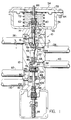
- Fig. 1 of the drawings is a vertical sectional view through the improved valve of the present invention and an illustrative actuator associated therewith, various valve members being illustrated in full line in a closed position and in broken line in open positions.
- Fig. 2 is a vertical sectional view similar to Fig. 1 but showing a valve forming a second embodiment of the present invention, a single discharge port and conduit replacing the dual discharge ports and conduits of the valve of Fig. 1.
- Fig. 3 is a fragmentary horizontal sectional view taken generally as indicated at 3, 3 in Figs. 1 and 2 illustrating small cooling steam passageways.
- Fig. 4 is an enlarged fragmentary section of a portion of the improved valve illustrating a steam valve and actuator member in a position wherein all passageways through the valve portion thereof are closed.
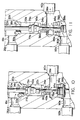
- Fig. 5 is a view similar to Fig. 4 but showing the steam valve and actuator member in a cooling steam position wherein the cooling steam passageway is open.
- Fig. 6 is a view similar to Figs. 4 and 5 but showing the valve and actuator member in the steam purge position.
- Fig. 7 is a view similar to Figs. 4 and 6 but showing the valve and actuator member in a burner operating position with oil supplied to the burner from the valve.
- Figs. 8 through 11 correspond precisely with Figs. 4 through 7 but illustrate the valve of Fig. 2.
- a valve constructed in accordance with the present invention is indicated generally at 10 ⁇ and comprises a central or intermediate body portion 12 which takes a cylindrical form and which has associated upper and lower closure members or plugs 14, 16.
- the plugs 14, 16 may be secured in assembled position by appropriate screws or the like not shown.
- a steam inlet port 18 communicates with a steam inlet chamber 20 ⁇ and a steam discharge chamber 22 communicates with steam discharge port 24.
- Steam inlet and discharge conduits 26, 28 are associated respectively with the inlet and discharge ports 18, 24.
- Steam valve seat 30 ⁇ has a central axial bore 32 which establishes communication between the steam inlet and discharge chambers 20 ⁇ , 22.
- purge valve seat 34 has a central axial bore 36 which establishes communication between chamber 22 and an oil discharge port 38 therebeneath.
- the oil discharge port 38 has a corresponding conduit 40 ⁇ which extends to an associated burner as does the steam discharge conduit 28.
- a steam supply passageway can be established by the steam inlet or supply conduit 26, steam inlet port 18, steam inlet chamber 20 ⁇ , steam valve bore 32, steam discharge chamber 22, steam discharge port 24 and steam discharge conduit 28.
- a steam purge passageway can be established by steam inlet or supply conduit 26, steam inlet port 18, steam inlet chamber 20 ⁇ , bore 32, steam discharge chamber 22, bore 36, discharge port 38 and oil discharge conduit 40 ⁇ .
- a combined steam valve and actuator member is provided and is indicated generally at 42.
- the steam valve and actuator member 42 includes a valve having upper and lower portions 44, 46 which cooperate respectively with the steam valve seat 30 ⁇ and the purge valve seat 34.
- An actuator portion of the member in the form of an elongated plunger or stem 48 has a function to be described more fully hereinbelow.
- Upwardly extending stem 50 ⁇ associated with the valve and actuator member has a sealing or packing means 52 associated therewith and extends therefrom upwardly in Fig. 1 to an actuating means.
- the actuating means for the steam valve and actuator member 42 may vary widely within the scope of the invention and may comprise pneumatic, hydraulic, electrical or other means.
- An illustrative actuating means indicated generally at 54 is of the pneumatic type.
- Two part housing 56, 58 for the actuator 54 comprises a lower cup shaped member secured in an upright position by nut 60 ⁇ threadably engaged with an appropriate threaded stud 62 which is formed on and projects axially upwardly from the plug or closure 14.
- Upper housing member 58 takes an inverted cup shape and is secured to the lower cup member by means of suitable annular flanges respectively on the upper and lower members and secured together by appropriate screws or bolts 64.
- An atmospheric port or vent 66 is provided in the lower housing member 56 and a supply or control port 68 in the upper housing member 58 may be connected with a controlled source of air or other gas under pressure.
- a diaphragm 70 ⁇ Disposed within the actuator housing is a diaphragm 70 ⁇ peripherally clamped between the housing flanges and attached to an upper end portion of the valve stem 50 ⁇ .
- a biasing or return spring 72 which may be of the coil type, has an upper end portion seated beneath the diaphragm 70 ⁇ and a lower end portion seated on the bottom wall of the lower cup shaped housing member 56.
- air or other gas under pressure may be supplied through the port 68 for actuation of the diaphragm 70 ⁇ , the stem 50 ⁇ and its valve and actuator member 42, the spring 72 supplying the necessary biasing or reaction force.
- appropriate control or regulation of air pressure will result in initial movement of the valve and actuator member 42 to an intermediate or purge position as illustrated by broken line 74.
- On an increase in the regulated pressure supplied through the port 68, further downward movement of the valve and actuator member 42 will occur to the broken line position of the valve illustrated at 76.
- a controlled reduction in supply pressure to the diaphragm 70 ⁇ will allow the return spring 72 to urge the diaphragm, stem, and valve and actuator member upwardly to its closed full line position.
- a step reduction in pressure may be employed to move the valve and actuator member sequentially from its lower-most broken line position 76 to its intermediate broken line position at 74 for a purge operation, and thereafter to the full line closed position.
- the second or purge passageway comprises steam inlet port 18, steam inlet chamber 20 ⁇ , bore 32, steam discharge chamber 22, bore 36, oil discharge port 38, and oil discharge conduit 40 ⁇ .
- the lower portion 46 of the valve closes the bore 36 in the purge seat 34 as illustrated and steam discharge through the oil discharge conduit 40 ⁇ is terminated.
- the actuator stem 48 associated with the steam valve 42 engages an oil valve member, indicated generally line at 78 in Fig. 6, and urges the same downwardly to its Fig. 7.
- the oil valve member 78 In its Fig. 6 position, the oil valve member 78 has a plug portion 82 which enters and closes a bore 84 in oil valve seat 86.
- the bore 84 is opened to an oil inlet chamber 88 therebeneath which in turn communicates with an oil inlet or supply port 90 ⁇ and an oil supply conduit 92.
- an oil supply passageway is established from the supply conduit 92 through the port 90 ⁇ , chamber 88, bore 84 to the oil discharge port 38 and its associated discharge conduit 40 ⁇ .
- This condition of the valve members prevails with the oil burner in operation and with atomizing steam flowing through the discharge conduit 28 and fuel oil similarly flowing to the burner through the discharge conduit 40 ⁇ .
- the oil valve 78 also has an associated stem 94 which extends downwardly therefrom past a sealing or packing device 96 to a biasing spring 98.
- the biasing spring 98 urges the oil valve member to its second or full line position at 78 and is compressed when the actuator member 48 urges the oil valve member downwardly to its first or broken line position at 80 ⁇ .
- An associated recirculation seat 10 ⁇ 0 ⁇ has a plurality of small openings 10 ⁇ 2, 10 ⁇ 2 provided therein. That is, the stem 94 extends downwardly through a central bore in the seat 10 ⁇ 0 ⁇ and the plurality of small valve openings 10 ⁇ 2, 10 ⁇ 2 are arranged circumaxially in the valve seat 10 ⁇ 0 ⁇ about the central bore and the stem 94.
- the valve 78 has a flat disc-like member 10 ⁇ 4 which cooperates with the valve openings 10 ⁇ 2, 10 ⁇ 2.
- disc 10 ⁇ 4 serves to close the openings 10 ⁇ 2, 10 ⁇ 2.
- a recirculation chamber 10 ⁇ 6 beneath seat 10 ⁇ 0 ⁇ receives oil from the openings 10 ⁇ 2, 10 ⁇ 2 and the oil in turn flows through a recirculation port 10 ⁇ 8 and a return conduit 110 ⁇ .
- the viscosity of the oil may thus be maintained at a low level through re-heating in its storage tank whenever the oil valve member 78 is in its full line or closed position.
- valve construction 10 ⁇ a forming a second embodiment of the present invention may be employed advantageously with mechanically atomized burners not requiring steam flow to the burners for atomization during burner operation.
- the valve 10 ⁇ a may be substantially identical in all respects with the valve 10 ⁇ of Fig. 1 except for the elimination of the steam discharge port 24 and its associated conduit 28.
- a single oil supply conduit 40 ⁇ a serves alternatively for a purge and oil supply or burner operation function.
- valve 10 ⁇ a of Fig. 2 Operation of the valve 10 ⁇ a of Fig. 2 for the supply of oil through the conduit 40 ⁇ a during burner operation is identical to that described above for valve 10 ⁇ and the provisions for recirculation of the oil through the conduit 110 ⁇ a may also be identical with those described above.
- the plug 77/77a which forms a part of steam valve and actuator member 42/42a is provided with four (4) small passageways 79/79a best illustrated in Fig. 3.
- the passageways 79/79a serve to control and meter steam flow during a "cooling" steam phase of operation when one or more burners may be inactive with other burners remaining in operation.
- a cooling steam passageway is established when steam valve and actuator member 42/42a is moved to its fourth position as illustrated in Figs. 5 and 9, an appropriate actuating pressure level having been established in actuator 54/54a through port 68/68a.
- the cooling steam passageway includes inlet port 18/18a, inlet chamber 20 ⁇ /20 ⁇ a, bore 32/32a, passageways 79/79a, bore 36/36a, port 38/38a and discharge conduit 40 ⁇ /40 ⁇ a.
- the passageways 79/79a are so dimensioned and located as to open prior to full opening movement of the valve portion of the valve and actuator member 42/42a.
- steam flow is under the control of small passageways 79/79a and may be metered as required for efficient burner tip cooling.
Landscapes
- Engineering & Computer Science (AREA)
- Chemical & Material Sciences (AREA)
- Combustion & Propulsion (AREA)
- Mechanical Engineering (AREA)
- General Engineering & Computer Science (AREA)
- Lift Valve (AREA)
- Feeding And Controlling Fuel (AREA)
- Nozzles For Spraying Of Liquid Fuel (AREA)
- Details Of Valves (AREA)
Abstract
Description
- In the firing of industrial oil burners and auxiliary or igniter burners associated with large oil fired utility or industrial boilers, it is a conventional practice to employ steam as an atomizing agent for the fuel oil. Moreover, the same source of steam is usually employed in purging fuel oil lines for safety and other considerations. A combination valve of the type under consideration according to the first portion of claim 1 which controls the supply of both steam and fuel oil.during firing and purging operations of burner systems is shown in US-A- 4,146,0̸56. This valve is particularly well suited to the efficient control of firing and purge operations as aforesaid and is quite satisfactory in all respects. There is, however, one additional feature recently found desirable and which is lacking in the patented valve.
- Further US-A-4454 892 shows a device which operates according to these lines. However, this valve operates in such a way that it takes an infinite number of positions and thus not meaningful control could be obtained.
- More particularly, if a burner "gun" is not retracted when removed from service while other "guns" are still in operation, the excessive heat encountered can do serious damage to the burner tip. It has been found, however, that it is possible to meter a small flow of steam through the gun and thus relatively "cool" the same and prevent damage thereto.
- It is a general object of the present invention to provide a steam and fuel oil supply valve of the type mentioned and which includes a simple and straight- forward means providing for the supply of a metered flow of "cooling" steam to an inoperative burner "gun" and thus prevent damage thereto.
- In fulfillment of the foregoing general object, according to the characterising portion of claim 1 an improved combination steam and fuel oil supply and purge valve is provided and comprises a valve body defining steam and oil inlet ports and at least one discharge port. An oil recirculation port is also provided. A steam purge passageway interconnects the steam inlet and the discharge port and an oil supply passageway interconnects the oil inlet port and the discharge port. An oil recirculation passageway interconnects the oil inlet port and the oil recirculation port. A cooling steam passageway interconnects the steam inlet port and the discharge port.
- A steam valve and actuator member is movable between first, second, third, and fourth positions in the valve body and is operable to open and close the steam purge and cooling steam passageways. An oil valve member which is movable between first and second positions respectively to open and close the oil supply passageway and to close and open the oil recirculation passageway has an associated biasing means which urges the same toward its second position. The steam valve and actuator member in its first and second positions respectively closes and opens the steam purge passageway. In its third position, the steam valve and actuator member closes the steam purge passageway and actuates the oil valve member whereby to urge the latter to its first position in opposition to its biasing means and thereby to open the oil supply passageway and close the oil recirculation passageway. The oil recirculation passageway has a normally open condition when the oil valve member is in its closed position. In its fourth position the steam valve and actuator member allows the oil valve member to close the oil supply passageway and opens the cooling steam passageway.
- More particularly, the valve body includes opposed spaced apart first and second valve seats each with a valve opening respectively for the control of supply and recirculation oil flow. The oil inlet port and the oil valve member are disposed between the first and second seats in the valve and the valve member is movable in one and an opposite direction between said first and second positions respectively. The first and second positions respectively represent engagement with the second and first seats whereby to open the oil passageway and close the recirculation passageway and to close the oil supply passageway and open the oil recirculation passageway.
- The actuator portion of the steam valve and actuator member preferably takes the form of an elongated plunger which is engagable with the oil valve member and operable to move the same to its first position when the steam valve and actuator resides in its third position. Thus the aforesaid sequence of operation is positively and mechanically assured.
- The specific construction of the oil valve member and its associated seats may vary but preferably comprises a plug type valve for a centrally bored oil supply seat. On an opposite side of the oil valve member a flat disc-like valve member is provided and the recirculation seat has a central opening for a valve stem with a plurality of small openings arranged circumaxially thereabout. Thus, the disc-like valve member opens and closes the small openings on engagement with the recirculation valve seat.
- Restriction or metering means in the cooling steam passageway preferably takes the form of at least one small metering passageway formed in the valve portion of the steam valve and actuator member. The said passageway is dimensioned and located to open prior to full opening movement of the valve portion of the member.
- When steam or perhaps air is required for atomizing, or other purposes, the combination valve of the invention is provided with both steam and oil discharge ports as described. Thus, during a purge operation both steam and oil discharge lines may be supplied with steam or air. During running or firing operation, oil is of course supplied to the oil discharge port and its associated conduit and thence to the burner while steam or air may be supplied to the steam discharge port and its associated conduit.
- In an alternative embodiment of the combination valve of the present invention, and when for example mechanically atomized burners are served by the valve, it is only necessary to provide a single discharge port and associated conduit. Thus, during a purge operation, steam or air may be provided from a steam inlet conduit and the associated steam port to the discharge port and its associated conduit. During burner operation, the discharge port and its associated conduit is of course supplied with fuel oil for delivery to the burner.
- Fig. 1 of the drawings is a vertical sectional view through the improved valve of the present invention and an illustrative actuator associated therewith, various valve members being illustrated in full line in a closed position and in broken line in open positions.
- Fig. 2 is a vertical sectional view similar to Fig. 1 but showing a valve forming a second embodiment of the present invention, a single discharge port and conduit replacing the dual discharge ports and conduits of the valve of Fig. 1.
- Fig. 3 is a fragmentary horizontal sectional view taken generally as indicated at 3, 3 in Figs. 1 and 2 illustrating small cooling steam passageways.
- Fig. 4 is an enlarged fragmentary section of a portion of the improved valve illustrating a steam valve and actuator member in a position wherein all passageways through the valve portion thereof are closed.
- Fig. 5 is a view similar to Fig. 4 but showing the steam valve and actuator member in a cooling steam position wherein the cooling steam passageway is open.
- Fig. 6 is a view similar to Figs. 4 and 5 but showing the valve and actuator member in the steam purge position.
- Fig. 7 is a view similar to Figs. 4 and 6 but showing the valve and actuator member in a burner operating position with oil supplied to the burner from the valve.
- Figs. 8 through 11 correspond precisely with Figs. 4 through 7 but illustrate the valve of Fig. 2.
- Referring particularly to Fig. 1, a valve constructed in accordance with the present invention is indicated generally at 10̸ and comprises a central or
intermediate body portion 12 which takes a cylindrical form and which has associated upper and lower closure members orplugs plugs steam inlet port 18 communicates with a steam inlet chamber 20̸ and asteam discharge chamber 22 communicates withsteam discharge port 24. Steam inlet anddischarge conduits discharge ports - Steam valve seat 30̸ has a central
axial bore 32 which establishes communication between the steam inlet and discharge chambers 20̸, 22. At a lower end portion of thechamber 22purge valve seat 34 has a centralaxial bore 36 which establishes communication betweenchamber 22 and anoil discharge port 38 therebeneath. Theoil discharge port 38 has a corresponding conduit 40̸ which extends to an associated burner as does the steam discharge conduit 28. - As will be apparent from the foregoing, a steam supply passageway can be established by the steam inlet or
supply conduit 26,steam inlet port 18, steam inlet chamber 20̸,steam valve bore 32,steam discharge chamber 22,steam discharge port 24 andsteam discharge conduit 28. Similarly, a steam purge passageway can be established by steam inlet orsupply conduit 26,steam inlet port 18, steam inlet chamber 20̸,bore 32,steam discharge chamber 22,bore 36,discharge port 38 and oil discharge conduit 40̸. - In accordance with the invention, a combined steam valve and actuator member is provided and is indicated generally at 42. The steam valve and
actuator member 42 includes a valve having upper andlower portions purge valve seat 34. An actuator portion of the member in the form of an elongated plunger orstem 48 has a function to be described more fully hereinbelow. Upwardly extending stem 50̸ associated with the valve and actuator member has a sealing or packing means 52 associated therewith and extends therefrom upwardly in Fig. 1 to an actuating means. - The actuating means for the steam valve and
actuator member 42 may vary widely within the scope of the invention and may comprise pneumatic, hydraulic, electrical or other means. An illustrative actuating means indicated generally at 54 is of the pneumatic type. Twopart housing actuator 54 comprises a lower cup shaped member secured in an upright position by nut 60̸ threadably engaged with an appropriate threadedstud 62 which is formed on and projects axially upwardly from the plug orclosure 14.Upper housing member 58 takes an inverted cup shape and is secured to the lower cup member by means of suitable annular flanges respectively on the upper and lower members and secured together by appropriate screws orbolts 64. An atmospheric port or vent 66 is provided in thelower housing member 56 and a supply or controlport 68 in theupper housing member 58 may be connected with a controlled source of air or other gas under pressure. Disposed within the actuator housing is a diaphragm 70̸ peripherally clamped between the housing flanges and attached to an upper end portion of the valve stem 50̸. A biasing or returnspring 72, which may be of the coil type, has an upper end portion seated beneath the diaphragm 70̸ and a lower end portion seated on the bottom wall of the lower cup shapedhousing member 56. - As will apparent, air or other gas under pressure may be supplied through the
port 68 for actuation of the diaphragm 70̸, the stem 50̸ and its valve andactuator member 42, thespring 72 supplying the necessary biasing or reaction force. Moreover, it will apparent that appropriate control or regulation of air pressure will result in initial movement of the valve andactuator member 42 to an intermediate or purge position as illustrated by broken line 74. On an increase in the regulated pressure supplied through theport 68, further downward movement of the valve andactuator member 42 will occur to the broken line position of the valve illustrated at 76. In the reverse direction, a controlled reduction in supply pressure to the diaphragm 70̸ will allow thereturn spring 72 to urge the diaphragm, stem, and valve and actuator member upwardly to its closed full line position. Alternatively and if desired, a step reduction in pressure may be employed to move the valve and actuator member sequentially from its lower-most broken line position 76 to its intermediate broken line position at 74 for a purge operation, and thereafter to the full line closed position. - In the first, full line, or closed position of the steam valve, its upper generally frusto-
conical portion 44 engages the steam seat 30̸ and aplug portion 77 thereabove enters the seat bore 32. Thus, the steam inlet orsupply port 18 and chamber 20̸ are effectively isolated from the remainder of the valve passageways, ports, and conduits. In the second or intermediate broken line position 74, the frusto-conical seating surface 44 is displaced axially downwardly from the steam seat 30̸ whereby to open the steam inlet chamber 20̸ to thesteam discharge chamber 22 through thebore 32 in the seat 30̸. Thus, a first passageway is provided interconnecting the steam inlet and discharge ports and comprisesinlet port 18, steam inlet chamber, bore 32 etc. as set forth above. Steam discharge flow through the conduit orline 28, however, may be regarded as merely incidental, purging of steam lines not ordinarily being required. - Steam flow through the aforementioned purge passageway is, however, highly significant and results in the desired purging of the oil line or conduit 40̸. The second or purge passageway comprises
steam inlet port 18, steam inlet chamber 20̸, bore 32,steam discharge chamber 22, bore 36,oil discharge port 38, and oil discharge conduit 40̸. - When the steam valve and
actuator member 42 is in its lower-most or third position, thelower portion 46 of the valve closes thebore 36 in thepurge seat 34 as illustrated and steam discharge through the oil discharge conduit 40̸ is terminated. At the same time, theactuator stem 48 associated with thesteam valve 42 engages an oil valve member, indicated generally line at 78 in Fig. 6, and urges the same downwardly to its Fig. 7. In its Fig. 6 position, theoil valve member 78 has a plug portion 82 which enters and closes abore 84 inoil valve seat 86. In its lower or Fig. 7 position, thebore 84 is opened to anoil inlet chamber 88 therebeneath which in turn communicates with an oil inlet or supply port 90̸ and anoil supply conduit 92. Thus, an oil supply passageway is established from thesupply conduit 92 through the port 90̸,chamber 88, bore 84 to theoil discharge port 38 and its associated discharge conduit 40̸. This condition of the valve members prevails with the oil burner in operation and with atomizing steam flowing through thedischarge conduit 28 and fuel oil similarly flowing to the burner through the discharge conduit 40̸. - The
oil valve 78 also has an associated stem 94 which extends downwardly therefrom past a sealing or packingdevice 96 to a biasingspring 98. The biasingspring 98 urges the oil valve member to its second or full line position at 78 and is compressed when theactuator member 48 urges the oil valve member downwardly to its first or broken line position at 80̸. An associated recirculation seat 10̸0̸ has a plurality of small openings 10̸2, 10̸2 provided therein. That is, the stem 94 extends downwardly through a central bore in the seat 10̸0̸ and the plurality of small valve openings 10̸2, 10̸2 are arranged circumaxially in the valve seat 10̸0̸ about the central bore and the stem 94. At a lower portion thereof thevalve 78 has a flat disc-like member 10̸4 which cooperates with the valve openings 10̸2, 10̸2. Thus, with the valve member at its lowermost position 80̸, disc 10̸4 serves to close the openings 10̸2, 10̸2. When the oil valve member is in its upperfull line position 78 the openings 10̸2, 10̸2 are open and in communication with theoil inlet chamber 88. Thus, a recirculation chamber 10̸6 beneath seat 10̸0̸ receives oil from the openings 10̸2, 10̸2 and the oil in turn flows through a recirculation port 10̸8 and a return conduit 110̸. As will be apparent, the viscosity of the oil may thus be maintained at a low level through re-heating in its storage tank whenever theoil valve member 78 is in its full line or closed position. - Referring now to Fig. 2, a valve construction 10̸a forming a second embodiment of the present invention may be employed advantageously with mechanically atomized burners not requiring steam flow to the burners for atomization during burner operation. The valve 10̸a may be substantially identical in all respects with the valve 10̸ of Fig. 1 except for the elimination of the
steam discharge port 24 and its associatedconduit 28. Thus, a single oil supply conduit 40̸a serves alternatively for a purge and oil supply or burner operation function. When steam valve andactuator member 42a is in the purge position as illustrated in broken line at 74a, steam flows from thesupply conduit 26a through thesteam inlet port 18a, steam inlet chamber 20̸a, bore 32a in seat 30̸a,chamber 22a, bore 36a inpurge seat 34a, and to theoil discharge port 38a and conduit 40̸a. - Operation of the valve 10̸a of Fig. 2 for the supply of oil through the conduit 40̸a during burner operation is identical to that described above for valve 10̸ and the provisions for recirculation of the oil through the conduit 110̸a may also be identical with those described above.
- Referring now to both Figs. 1 and 2, it will be observed that the
plug 77/77a which forms a part of steam valve andactuator member 42/42a is provided with four (4)small passageways 79/79a best illustrated in Fig. 3. Thepassageways 79/79a serve to control and meter steam flow during a "cooling" steam phase of operation when one or more burners may be inactive with other burners remaining in operation. A cooling steam passageway is established when steam valve andactuator member 42/42a is moved to its fourth position as illustrated in Figs. 5 and 9, an appropriate actuating pressure level having been established inactuator 54/54a throughport 68/68a. The cooling steam passageway includesinlet port 18/18a, inlet chamber 20̸/20̸a, bore 32/32a, passageways 79/79a, bore 36/36a,port 38/38a and discharge conduit 40̸/40̸a. As will be apparent thepassageways 79/79a are so dimensioned and located as to open prior to full opening movement of the valve portion of the valve andactuator member 42/42a. Thus, steam flow is under the control ofsmall passageways 79/79a and may be metered as required for efficient burner tip cooling. - From the foregoing, it will be apparent that a desirably simple and straight-forward cooling steam feature is provided in the steam and fuel oil supply and purge valve of the present invention. Burner tip cooling is achieved in an efficient and fool proof manner and a substantially improved valve construction and operation results.
Claims (3)
- A steam and fuel oil supply and purge valve comprising a valve body (12) defining steam and oil inlet ports, (18) and (90) respectively, at least one discharge port (24), a steam purge passageway interconnecting said steam inlet (18) and discharge (24) ports, an oil supply passageway interconnecting said oil inlet (90) and discharge (38) ports, a cooling steam passageway interconnecting said steam inlet and discharge ports (18) and (24) respectively, a steam valve and actuator member (42) movable between first, second, third, and fourth positions in said valve body (12) and operable to open and close said steam purge and cooling steam passageways, an oil valve member (82) movable between first and second positions to open and close said oil supply passageway, biasing means (72) urging said oil valve member (82) toward its second and closed position, said steam valve and actuator member (42) in its first and second positions respectively closing and opening said steam purge passageway, and said valve and actuator member (42) in its third position closing said steam purge passageway and actuating said oil valve member (82) whereby to urge said member to its first position in opposition to said biasing means (72) and thereby open said oil supply passageway, and said steam valve and actuator member (42) in its fourth position allowing said oil valve member (82) to close said oil supply passageway at the urging of said biasing means (72) and opening said restricted cooling steam passageway, characterized in that said cooling steam passageway includes restriction means which takes the form of at least one small metering passageway (79) in said steam valve and actuator member (42) which is dimensioned and located to open prior to full opening movement of the valve member and actuator (42) relative to its seat (30)
- A steam and fuel oil supply and purge valve according to claim 1, characterized in that the valve is provided with an oil recirculation port (108) and return conduit (110) in communication with said oil supply port when the oil valve member (82) is in its closed position.
- A steam and fuel oil supply and purge valve according to claim 1, characterized in that a steam supply passageway is arranged which interconnects said steam inlet (18) and discharge (24) ports.
Applications Claiming Priority (2)
| Application Number | Priority Date | Filing Date | Title |
|---|---|---|---|
| US07/493,217 US5048563A (en) | 1990-03-14 | 1990-03-14 | Steam and fuel oil supply and purge valve with cooling steam feature |
| US493217 | 1990-03-14 |
Publications (2)
| Publication Number | Publication Date |
|---|---|
| EP0472691A1 EP0472691A1 (en) | 1992-03-04 |
| EP0472691B1 true EP0472691B1 (en) | 1993-12-01 |
Family
ID=23959361
Family Applications (1)
| Application Number | Title | Priority Date | Filing Date |
|---|---|---|---|
| EP91905741A Expired - Lifetime EP0472691B1 (en) | 1990-03-14 | 1991-03-04 | Steam and fuel oil supply and purge valve with cooling steam feature |
Country Status (8)
| Country | Link |
|---|---|
| US (1) | US5048563A (en) |
| EP (1) | EP0472691B1 (en) |
| JP (1) | JP3035344B2 (en) |
| KR (1) | KR100193320B1 (en) |
| AU (1) | AU7465391A (en) |
| CA (1) | CA2057927C (en) |
| DE (1) | DE69100713T2 (en) |
| WO (1) | WO1991014134A1 (en) |
Families Citing this family (12)
| Publication number | Priority date | Publication date | Assignee | Title |
|---|---|---|---|---|
| US5469880A (en) * | 1994-12-16 | 1995-11-28 | Tetra Laval Holdings & Finance, S.C. | Manifold valve assemblies with cleaning solution supply |
| EP1486707B1 (en) * | 2003-06-11 | 2007-11-21 | Asm International N.V. | Gas supply system, valve assembly and method of forming reactant pulses by operating a valve assembly |
| US8905075B2 (en) | 2009-07-13 | 2014-12-09 | Idex Health & Science Llc | Rotary shear valve assembly with hard-on-hard seal surfaces |
| US8876081B2 (en) | 2009-07-13 | 2014-11-04 | Idex Health & Science Llc | Rotary shear valve assembly with a polymer insert device |
| US10073071B2 (en) | 2010-06-07 | 2018-09-11 | David Deng | Heating system |
| US10222057B2 (en) | 2011-04-08 | 2019-03-05 | David Deng | Dual fuel heater with selector valve |
| US9739389B2 (en) | 2011-04-08 | 2017-08-22 | David Deng | Heating system |
| US9200802B2 (en) | 2011-04-08 | 2015-12-01 | David Deng | Dual fuel heater with selector valve |
| US9175848B2 (en) * | 2011-12-05 | 2015-11-03 | David Deng | Dual fuel heater with selector valve |
| CN102506198B (en) * | 2011-10-20 | 2013-05-22 | 南京普鲁卡姆电器有限公司 | Dual-gas-source gas self-adaptive main control valve |
| US9752779B2 (en) | 2013-03-02 | 2017-09-05 | David Deng | Heating assembly |
| US20140248567A1 (en) * | 2013-03-02 | 2014-09-04 | David Deng | Safety pilot |
Family Cites Families (6)
| Publication number | Priority date | Publication date | Assignee | Title |
|---|---|---|---|---|
| US3065783A (en) * | 1958-11-12 | 1962-11-27 | Combustion Eng | Control valve for start up and shut down of atomizing oil burners |
| US3939871A (en) | 1975-01-28 | 1976-02-24 | Rockwell International Corporation | Burner block assembly |
| US4146056A (en) * | 1976-11-11 | 1979-03-27 | Bascom Frank Buchanan | Steam and fuel oil control and purge valve |
| US4579143A (en) * | 1982-08-23 | 1986-04-01 | Maxon Corporation | Control and purge valve for atomization of heavy fuel oil for combustion |
| US4454892A (en) * | 1982-09-13 | 1984-06-19 | Combustion Engineering, Inc. | Atomizing oil valve improvement |
| US4823843A (en) * | 1988-06-01 | 1989-04-25 | Aptec, Inc. | Valve apparatus |
-
1990
- 1990-03-14 US US07/493,217 patent/US5048563A/en not_active Expired - Lifetime
-
1991
- 1991-03-04 KR KR1019910701599A patent/KR100193320B1/en not_active Expired - Lifetime
- 1991-03-04 DE DE69100713T patent/DE69100713T2/en not_active Expired - Fee Related
- 1991-03-04 CA CA002057927A patent/CA2057927C/en not_active Expired - Lifetime
- 1991-03-04 AU AU74653/91A patent/AU7465391A/en not_active Abandoned
- 1991-03-04 EP EP91905741A patent/EP0472691B1/en not_active Expired - Lifetime
- 1991-03-04 WO PCT/US1991/001463 patent/WO1991014134A1/en not_active Ceased
- 1991-03-04 JP JP03506141A patent/JP3035344B2/en not_active Expired - Fee Related
Also Published As
| Publication number | Publication date |
|---|---|
| KR920701758A (en) | 1992-08-12 |
| AU7465391A (en) | 1991-10-10 |
| KR100193320B1 (en) | 1999-06-15 |
| JPH04506250A (en) | 1992-10-29 |
| EP0472691A1 (en) | 1992-03-04 |
| DE69100713T2 (en) | 1994-06-01 |
| WO1991014134A1 (en) | 1991-09-19 |
| CA2057927C (en) | 2000-11-14 |
| CA2057927A1 (en) | 1991-09-15 |
| JP3035344B2 (en) | 2000-04-24 |
| DE69100713D1 (en) | 1994-01-13 |
| US5048563A (en) | 1991-09-17 |
Similar Documents
| Publication | Publication Date | Title |
|---|---|---|
| US5048790A (en) | Self-modulating control valve for high-pressure fluid flow | |
| US6250063B1 (en) | Fuel staging apparatus and methods for gas turbine nozzles | |
| US2724239A (en) | Fuel flow distributing and manifold pressurizing valve for dual orifice fuel injection nozzles | |
| US5048563A (en) | Steam and fuel oil supply and purge valve with cooling steam feature | |
| US5937846A (en) | Fluid control assembly | |
| EP0644375A2 (en) | Fuel purging fuel injector | |
| US4146056A (en) | Steam and fuel oil control and purge valve | |
| US5090451A (en) | Combination steam and fuel oil supply and purge valve with recirculation feature | |
| US3785570A (en) | Dual orifice fuel nozzle with air-assisted primary at low flow rates | |
| CA1160919A (en) | Dual fuel supply system | |
| US3095153A (en) | Variable area spray nozzle | |
| US4694810A (en) | Fuel cock for an internal combustion engine | |
| US4749005A (en) | Combined gas pressure regulator and shut off valve | |
| EP0472723B1 (en) | Improved combination steam and fuel oil supply and purge valve with recirculation feature | |
| US3091926A (en) | Oil burners | |
| US5024385A (en) | Internal combustion engine fuel supply system | |
| US2552658A (en) | Nozzle for gas turbines | |
| US4424666A (en) | Fuel control system and apparatus for gas turbine engine | |
| GB1581005A (en) | Valve | |
| SU1098526A3 (en) | Injection nozzle | |
| CA1097183A (en) | Steam and fuel oil control and purge valve | |
| GB2107846A (en) | Burner | |
| US3923079A (en) | Fluid control valve | |
| US706050A (en) | Mixing-valve for gas or gasolene engines. | |
| CN2335058Y (en) | Mixed liquid fuel stove |
Legal Events
| Date | Code | Title | Description |
|---|---|---|---|
| PUAI | Public reference made under article 153(3) epc to a published international application that has entered the european phase |
Free format text: ORIGINAL CODE: 0009012 |
|
| 17P | Request for examination filed |
Effective date: 19911113 |
|
| AK | Designated contracting states |
Kind code of ref document: A1 Designated state(s): BE CH DE FR GB IT LI SE |
|
| 17Q | First examination report despatched |
Effective date: 19920410 |
|
| GRAA | (expected) grant |
Free format text: ORIGINAL CODE: 0009210 |
|
| AK | Designated contracting states |
Kind code of ref document: B1 Designated state(s): BE CH DE FR GB IT LI SE |
|
| REF | Corresponds to: |
Ref document number: 69100713 Country of ref document: DE Date of ref document: 19940113 |
|
| ET | Fr: translation filed | ||
| ITF | It: translation for a ep patent filed | ||
| PLBE | No opposition filed within time limit |
Free format text: ORIGINAL CODE: 0009261 |
|
| STAA | Information on the status of an ep patent application or granted ep patent |
Free format text: STATUS: NO OPPOSITION FILED WITHIN TIME LIMIT |
|
| 26N | No opposition filed | ||
| EAL | Se: european patent in force in sweden |
Ref document number: 91905741.4 |
|
| PGFP | Annual fee paid to national office [announced via postgrant information from national office to epo] |
Ref country code: BE Payment date: 20010122 Year of fee payment: 11 |
|
| PGFP | Annual fee paid to national office [announced via postgrant information from national office to epo] |
Ref country code: GB Payment date: 20010228 Year of fee payment: 11 |
|
| PGFP | Annual fee paid to national office [announced via postgrant information from national office to epo] |
Ref country code: CH Payment date: 20010302 Year of fee payment: 11 |
|
| PGFP | Annual fee paid to national office [announced via postgrant information from national office to epo] |
Ref country code: FR Payment date: 20010315 Year of fee payment: 11 |
|
| PGFP | Annual fee paid to national office [announced via postgrant information from national office to epo] |
Ref country code: SE Payment date: 20010322 Year of fee payment: 11 |
|
| PGFP | Annual fee paid to national office [announced via postgrant information from national office to epo] |
Ref country code: DE Payment date: 20010523 Year of fee payment: 11 |
|
| REG | Reference to a national code |
Ref country code: GB Ref legal event code: IF02 |
|
| PG25 | Lapsed in a contracting state [announced via postgrant information from national office to epo] |
Ref country code: GB Free format text: LAPSE BECAUSE OF NON-PAYMENT OF DUE FEES Effective date: 20020304 |
|
| PG25 | Lapsed in a contracting state [announced via postgrant information from national office to epo] |
Ref country code: SE Free format text: LAPSE BECAUSE OF NON-PAYMENT OF DUE FEES Effective date: 20020305 |
|
| PG25 | Lapsed in a contracting state [announced via postgrant information from national office to epo] |
Ref country code: LI Free format text: LAPSE BECAUSE OF NON-PAYMENT OF DUE FEES Effective date: 20020331 Ref country code: CH Free format text: LAPSE BECAUSE OF NON-PAYMENT OF DUE FEES Effective date: 20020331 Ref country code: BE Free format text: LAPSE BECAUSE OF NON-PAYMENT OF DUE FEES Effective date: 20020331 |
|
| BERE | Be: lapsed |
Owner name: *ITT INDUSTRIES INC. Effective date: 20020331 |
|
| PG25 | Lapsed in a contracting state [announced via postgrant information from national office to epo] |
Ref country code: DE Free format text: LAPSE BECAUSE OF NON-PAYMENT OF DUE FEES Effective date: 20021001 |
|
| EUG | Se: european patent has lapsed |
Ref document number: 91905741.4 |
|
| GBPC | Gb: european patent ceased through non-payment of renewal fee |
Effective date: 20020304 |
|
| REG | Reference to a national code |
Ref country code: CH Ref legal event code: PL |
|
| PG25 | Lapsed in a contracting state [announced via postgrant information from national office to epo] |
Ref country code: FR Free format text: LAPSE BECAUSE OF NON-PAYMENT OF DUE FEES Effective date: 20021129 |
|
| REG | Reference to a national code |
Ref country code: FR Ref legal event code: ST |
|
| PG25 | Lapsed in a contracting state [announced via postgrant information from national office to epo] |
Ref country code: IT Free format text: LAPSE BECAUSE OF NON-PAYMENT OF DUE FEES Effective date: 20050304 |