EP0472660B1 - A pen - Google Patents
A pen Download PDFInfo
- Publication number
- EP0472660B1 EP0472660B1 EP90909242A EP90909242A EP0472660B1 EP 0472660 B1 EP0472660 B1 EP 0472660B1 EP 90909242 A EP90909242 A EP 90909242A EP 90909242 A EP90909242 A EP 90909242A EP 0472660 B1 EP0472660 B1 EP 0472660B1
- Authority
- EP
- European Patent Office
- Prior art keywords
- ink
- nib
- chamber
- valve
- pen
- Prior art date
- Legal status (The legal status is an assumption and is not a legal conclusion. Google has not performed a legal analysis and makes no representation as to the accuracy of the status listed.)
- Expired - Lifetime
Links
Images


Classifications
-
- B—PERFORMING OPERATIONS; TRANSPORTING
- B43—WRITING OR DRAWING IMPLEMENTS; BUREAU ACCESSORIES
- B43K—IMPLEMENTS FOR WRITING OR DRAWING
- B43K5/00—Pens with ink reservoirs in holders, e.g. fountain-pens
- B43K5/02—Ink reservoirs
- B43K5/10—Ink reservoirs with reserve ink chambers
-
- B—PERFORMING OPERATIONS; TRANSPORTING
- B43—WRITING OR DRAWING IMPLEMENTS; BUREAU ACCESSORIES
- B43K—IMPLEMENTS FOR WRITING OR DRAWING
- B43K5/00—Pens with ink reservoirs in holders, e.g. fountain-pens
- B43K5/18—Arrangements for feeding the ink to the nibs
- B43K5/1818—Mechanical feeding means, e.g. valves; Pumps
- B43K5/1827—Valves
- B43K5/1836—Valves automatically closing
- B43K5/1845—Valves automatically closing opened by actuation of the writing point
Definitions
- This invention relates to writing instruments and more particularly to reservoir pens.
- a reservoir pen having a barrel enclosing an ink reservoir, a nib, a feed bar underlying the nib and defining an ink feed channel for supplying ink from the reservoir to the underside of the nib, and a valve for closing the ink feed channel coupled to the nib to be opened thereby upon application of the nib against a surface during writing to allow ink to flow to the nib.
- the advantage of a valve is that it can prevent the ink drying up in the feed channel during periods of non-use.
- Such a pen present difficulties in controlling ink flow from the reservoir when the valve is opened.
- the feed channel and/or valve must be made to such close tolerances that it cannot be manufactured economically by present day production methods.
- U.S. Patent 4,547,090 is concerned with such a reservoir pen in which a valve is controlled by movement of the tip to permit or prevent flow of ink to the nib.
- a pen having a primary ink reservoir chamber, a secondary ink reservoir chamber in fluid communication with said first chamber, a nib, an ink feed channel for conducting ink from said second chamber to said nib and a valve associated with said ink feed channel to control flow of ink to said nib, characterized in that the valve includes a spring biassed valve member and a cooperating valve seat, said valve member having a plug portion and a piston depending from said plug portion and disposed within said channel to draw ink out of said channel as the plug portion is lifted from said valve seat, and in that a flow restrictor is interposed between said first and second ink reservoir chambers.
- the ink flow rate is conveniently controlled by including suitable flow restricting means within the reservoir structure, whereby the flow regulating duty is taken away from the ink feed channel and/or valve so that the latter becomes a simple on-off valve and the severe tolerancing demands on these components are obviated.
- the flow restricting means can be any device, member or element capable of allowing ink to flow through or past at a controlled maximum rate. Very satisfactory results have been achieved with an element of microporous material consisting of a length cut off from an extruded plastics rod having capillary channels extending along its length. With such material, which may be the same as that sometimes used as porous writing tips in other writing instruments, the flow resistance can readily be adjusted by taking longer or shorter lengths.
- the secondary ink reservoir can be of very substantially smaller capacity than the primary chamber where nearly all of the ink is stored, the secondary chamber being included to ensure a volume of ink immediately available for supply to the valve and hence the nib when the valve is opened.
- the reducible volume reservoir may take different forms, such a flaccid sack, but in a preferred embodiment comprises a cylindrical body and a grease plug which slides along the body following the ink as it is used up.
- the grease plug incorporates a reinforcement frame of rigid material.
- the frame which consists of a skeletal structure defining a large contact area for the grease and dimensioned to fit freely within the reservoir body so that a layer of grease is always present between them has been found to help maintain the integrity of the grease mass, especially when large diameter reservoir bodies are concerned.
- the frame can also serve to limit contact between the grease and atmosphere air which can lead to oxidation and drying out of the grease whereby the performance of the grease plug is impaired.
- the frame comprises a plurality of radial fins e.g. 3 to 6 in number, and a transverse disc at the trailing end of the fins and possibly apertured to facilitate insertion of the frame into the grease.
- the reinforcement frame means that a large diameter body and hence large volume chamber are feasible and the body may be constituted by the pen barrel itself. It even becomes commercially acceptable for the pen to be of the so-called disposable type intended to be discarded when the reservoir has been emptied of ink.
- valve seat is formed in the feed bar underlying the nib and surrounding the ink feed channel opening.
- the valve member is made of a material softer than that of the seat to ensure good sealing engagement, and is shaped to define with the seat an ink duct which decreases in width in the downstream direction so that flow of ink through the opened valve is assisted by capillary attraction.
- the valve member includes a part which projects into the ink feed channel and serves to draw ink through the channel as the valve is opened to aid the initial supply of ink to the writing tip of the nib.
- the valve member conveniently takes the form of a plug which passes through a hole in the nib and is urged to a closed position by a spring member acting on its outer end. Movement of the nib under normal writing pressure causes it to lift the valve plug to open the valve, the movement of the nib being limited by stop means provided thereon engaging an abutment on the feed bar.
- the pen illustrated in Figures 1 to 9 of the drawings is intended to be discarded after the initial ink charge has been completely depleted. It comprises a tubular barrel 1 which also serves to define a primary reservoir chamber 2 as will become clear, a feed bar 3 fitted to the forward end of the barrel 1 and mounting the pen nib 4, and a grease plug 5 received in the rear end of the barrel immediately behind the column of ink stored in the chamber 2.
- the feed bar has an axial bore which is stepped to define three main sections, namely a rear section of large diameter which defines a portion of the primary reservoir chamber, an intermediate section, and a forward section which constitutes a secondary ink reservoir chamber 6.
- a flow restrictor device Accommodated in the intermediate bore section and separating the primary and secondary reservoir chambers is a flow restrictor device consisting of an extruded rod 8 of plastics having one or more capillaries extending longitudinally through the rod, and a tubular holder 9 for supporting the rod in the feed bar so that the ink is constrained to flow through the restrictor in passing from the primary to the secondary reservoir chamber.
- the flow resistance produced by the restrictor is determined by the length of the rod 8 and can therefore be adjusted by using longer or shorter lengths of rod.
- the capacity of chamber 6 can be very small and is very much less than that of the primary chamber 2.
- An ink feed channel 10 leads from the secondary reservoir chamber to the upper side of the feed bar, and an annular valve seat 11 extends around the channel for cooperation with a valve member 12 formed by a plug 13.
- the plug extends through a hole provided in the nib 4 and has an enlarged head 14 which overlies the nib so that movement of the nib away from the feed bar due to the writing point of the nib being pressed down on a sheet of paper during writing causes the plug 13 to be lifted and the valve member 12 to be raised from the valve seat 11 to allow ink to flow out through the feed channel 10.
- the inner end of the plug is shaped as a piston 15 which acts to draw the ink out of the feed channel with a pump-like action as the plug 13 is lifted.
- the domed valve member cooperates with a part-spherical socket formed in the feed bar downstream of the valve seat to define an annular ink duct or channel 16 (Fig. 5) which narrows in width away from the seat so that the capillary forces tend to draw the ink out from the ink feed channel.
- the feed bar 3, and hence the valve seat are formed of relatively hard material, such as polycarbonate and the plug 13 is made of a softer material, e.g. high density polyethylene, so that a good seal will be obtained between the valve member and seat despite any surface irregularities.
- the outer surface of the feed bar is provided with a longitudinal groove 18 extending from the socket towards the free end of the feed bar, this groove tapering in depth and width to define a capillary aiding flow of ink to the writing tip of the nib 4.
- the nib is slit from its tip to the hole in which the plug 13 is inserted, the slit forming the final part of the ink flow path to the writing tip.
- the rear end of the nib is supported on a slightly raised shoulder 20 formed on the feed bar and the nib also rests against the feed bar at the forward end of the latter under the influence of a leaf spring 21.
- a gap which tapers forwardly to encourage by capillary action flow of ink in that direction.
- the feed bar is formed with a latching projection 23 which engages in a hole 24 in the nib.
- the sides of the nib are bent to define L-shaped extensions providing stops 24 underlying lateral abutment shoulders 25 provided on opposite sides of the feed bar (Fig. 4).
- the stops 24 engage the shoulders 25 to limit the movement of the nib away from the feed bar to that necessary to open the valve and allow essentially free flow of ink out of the feed channel 10.
- the valve is not required to regulate the ink flow rate, this function being performed by the rod 8 of the flow restrictor which regulates the flow of ink out of the secondary reservoir chamber by controlling the flow of replacement ink into this chamber from the primary reservoir chamber.
- a second leaf spring 28 acts on the head 14 of plug 13 urging the valve member into the closed position.
- the plug could be fixed to the nib but for ease of manufacturing it is preferred that they should be separate and be acted upon by the respective springs 21, 28.
- the springs are nonetheless provided by a unitary spring component 30 which includes a mounting collar 32 surrounding the feed bar and from which projects a finger constituting the spring 28, the spring 21 being formed by a central part stamped out of this finger.
- the collar 32 is notched to receive a location pip 33 to ensure correct rotational positioning of the spring on the feed bar.
- the grease plug 5 consists of a mass of grease material and a reinforcing frame or cage which is shown in Figures 6 to 9.
- the cage comprises a central hub 40 with a pointed end and from which project four radial fins 41 spaced uniformly around the hub. At the trailing end there is a circular disc 42 with holes 43 which register with the spaces between the fins 41.
- the outer diameter of the cage is less than the inner diameter of the barrel, preferably by an amount to allow a grease layer at least in the order of 0.1mm thick between them. Furthermore, to resist breakup of the grease plug it is preferable for there to be a solid mass of grease extending at least about 5mm forwardly from the front end of the reinforcing cage.
- the grease plug slides forward along the barrel maintaining contact with the ink.
- the cage reduces the shear forces within the mass of grease, by confining the shearing forces to a thin layer of grease adjacent the reservoir wall, so that the integrity of the grease mass remains intact despite the large diameter of the barrel and the low viscosity of the agueous ink which may be used in the pen. If the disc 42 of the cage is positioned to cover the surface of the grease it reduces contact with atmosphere so that hardening or softening of the grease due to drying out and oxidation, which can have deleterious effects on the ability of the grease to follow the ink movement, are essentially precluded.
- the area of contact is mainly confined to the holes 43 and in extreme cases these could be filled in after insertion of the cage into the grease.
- the necessity for the ink in the primary chamber 2 to pull the grease plug along behind as it flows out of the pen means that the grease plug itself has some restricting effect on the ink flow rate.
- the flow restrictor can be arranged to make allowance for that resistance so that the required flow rate is obtained.
- FIG. 10-12 An alternative form of grease plug reinforcing cage is illustrated in Figures 10-12. It is generally similar in form to the cage of Figs. 6-9 in that it is a unitary member including four uniformly spaced radial fins 51 and a circular disc 52 at the upper end.
- the cage has a central bore 53 extending through the disc 52, thereby to serve the same purpose of the holes 43 in the first embodiment, and extending along the fins but terminating short of their free lower ends.
- the bore is of sufficient diameter that it provides direct communication between the inter-fin spaces, which helps to maintain the integrity of the grease plug due to the grease segments filling said spaces being directly connected through the cage.
- the lower end corners of the fins are radiused to assist in guiding the cage along the reservoir body, and also to encourage bubbles of air to pass out between the grease plug and the reservoir. Also to encourage the passage of air bubbles and minimise friction the fins are reduced in radial width above their lower end portions.
- the disc 52 is formed with notches 54 in alignment with the fins to prolong the air escape path past the disc. The function and use of the grease cage are the same as described above with respect to Figs. 6-9.
- FIG. 14-16 A second embodiment of a pen according to the invention is shown in Figures 14-16.
- the pen is essentially the same as that of Figs. 1-5, and the same reference numerals have been used to denote corresponding parts in the drawings of the respective embodiments.
- the main difference at the forward or writing end of the pen is the addition of a shroud member 60 which serves to lock the spring component 30 in place on the feed bar 3, and which also acts to conceal the springs 21, 28 and the valve plug 13 whereby they are protected against damage and the overall appearance of the writing tip is enhanced.
- the shroud member includes a collar 61 which engages with a snap fit in the forward end of the pen barrel 1.
- the collar also abuts against a flange 62 on the feed bar to hold it against an internal shoulder formed in the barrel, thereby securing the feed bar in the barrel.
- An integral finger portion 63 of the shroud member projects forwardly from the collar 61 and covers the springs 21, 28 and valve plug 13.
- the spring component 30 has a tail 64 bent around the rear edge of the shroud member and located in a longitudinal groove provided in the outer surface of its collar 61.
- the spring tail 64 is captured and held firmly between the shroud member 60 and the barrel 1, so that the spring component is anchored securely in position.
- the end of the barrel not to be left entirely open as in Figure 1.
- the rear end of the barrel 1 is equipped with a closure member in the form of a plug 65 pushed with a tight fit into the end of the barrel. Steps need to be taken to avoid a vacuum being created behind the grease plug 5 as it is moved forwardly due to the ink in the reservoir being used up, since a vacuum would oppose such movement and possibly lead to disintegration of the grease plug.
- an air vent is provided and is formed by a longitudinal groove 66 extending along the inside of the barrel 1 and a notch 67 in the end of the barrel which defines an air port with the plug 65.
- the cage reinforcing the grease plug 5 is completely embedded in the grease.
- the fact that there is only restricted communication with ambient atmosphere through the narrow vent passage means contact of air with the grease is minimal and hence its adverse affects on the grease are diminished to acceptable levels.
- the feed bar 3 and shroud member 60, with the other pen parts carried thereby will be assembled with the barrel 1 following which the primary reservoir 2 will be filled with ink, the grease plug 5 and its stabilising cage will be introduced, and finally the plug 65 will be fitted. The pen is intended to be discarded when all the ink has been consumed.
- the pen could alternatively be arranged to accept ink cartridges or to be otherwise refillable, but if it is to be filled through the writing end steps would need to be taken to bypass the valve (or to ensure it was open) and bypass the flow restrictor 8 to allow ink to flow into the main reservoir chamber 2 at an acceptable rate during filling operations.
Landscapes
- Engineering & Computer Science (AREA)
- Mechanical Engineering (AREA)
- Pens And Brushes (AREA)
Abstract
Description
- This invention relates to writing instruments and more particularly to reservoir pens.
- It has been proposed to construct a reservoir pen having a barrel enclosing an ink reservoir, a nib, a feed bar underlying the nib and defining an ink feed channel for supplying ink from the reservoir to the underside of the nib, and a valve for closing the ink feed channel coupled to the nib to be opened thereby upon application of the nib against a surface during writing to allow ink to flow to the nib. The advantage of a valve is that it can prevent the ink drying up in the feed channel during periods of non-use. Such a pen present difficulties in controlling ink flow from the reservoir when the valve is opened. In order to achieve a regulated ink flow the feed channel and/or valve must be made to such close tolerances that it cannot be manufactured economically by present day production methods.
- U.S. Patent 4,547,090 is concerned with such a reservoir pen in which a valve is controlled by movement of the tip to permit or prevent flow of ink to the nib.
- According to the present invention, there is provided a pen having a primary ink reservoir chamber, a secondary ink reservoir chamber in fluid communication with said first chamber, a nib, an ink feed channel for conducting ink from said second chamber to said nib and a valve associated with said ink feed channel to control flow of ink to said nib, characterized in that the valve includes a spring biassed valve member and a cooperating valve seat, said valve member having a plug portion and a piston depending from said plug portion and disposed within said channel to draw ink out of said channel as the plug portion is lifted from said valve seat, and in that a flow restrictor is interposed between said first and second ink reservoir chambers.
- The ink flow rate is conveniently controlled by including suitable flow restricting means within the reservoir structure, whereby the flow regulating duty is taken away from the ink feed channel and/or valve so that the latter becomes a simple on-off valve and the severe tolerancing demands on these components are obviated. The flow restricting means can be any device, member or element capable of allowing ink to flow through or past at a controlled maximum rate. Very satisfactory results have been achieved with an element of microporous material consisting of a length cut off from an extruded plastics rod having capillary channels extending along its length. With such material, which may be the same as that sometimes used as porous writing tips in other writing instruments, the flow resistance can readily be adjusted by taking longer or shorter lengths.
- The secondary ink reservoir can be of very substantially smaller capacity than the primary chamber where nearly all of the ink is stored, the secondary chamber being included to ensure a volume of ink immediately available for supply to the valve and hence the nib when the valve is opened.
- In conventional fountain pens air must enter the ink reservoir chamber to replace the ink as it is used up. Expansion of the air within the reservoir due to changes in temperature and/or ambient pressure (e.g. when carried on an aeroplane) can cause ink to be expelled. This disadvantage is avoided in the pen described in the present specification by virtue of the fact that the primary reservoir chamber is made so that it reduces in volume as the ink is used. This means that the need for air to enter the reservoir is precluded and the reservoir system remains a closed ink-filled system. The reducible volume reservoir may take different forms, such a flaccid sack, but in a preferred embodiment comprises a cylindrical body and a grease plug which slides along the body following the ink as it is used up.
- In accordance with a novel feature of the invention the grease plug incorporates a reinforcement frame of rigid material. The frame which consists of a skeletal structure defining a large contact area for the grease and dimensioned to fit freely within the reservoir body so that a layer of grease is always present between them has been found to help maintain the integrity of the grease mass, especially when large diameter reservoir bodies are concerned. The frame can also serve to limit contact between the grease and atmosphere air which can lead to oxidation and drying out of the grease whereby the performance of the grease plug is impaired. In one particular construction the frame comprises a plurality of radial fins e.g. 3 to 6 in number, and a transverse disc at the trailing end of the fins and possibly apertured to facilitate insertion of the frame into the grease.
- The reinforcement frame means that a large diameter body and hence large volume chamber are feasible and the body may be constituted by the pen barrel itself. It even becomes commercially acceptable for the pen to be of the so-called disposable type intended to be discarded when the reservoir has been emptied of ink.
- Also provided by the invention is a novel valve structure for the pen. The valve seat is formed in the feed bar underlying the nib and surrounding the ink feed channel opening. The valve member is made of a material softer than that of the seat to ensure good sealing engagement, and is shaped to define with the seat an ink duct which decreases in width in the downstream direction so that flow of ink through the opened valve is assisted by capillary attraction. In addition, the valve member includes a part which projects into the ink feed channel and serves to draw ink through the channel as the valve is opened to aid the initial supply of ink to the writing tip of the nib. The valve member conveniently takes the form of a plug which passes through a hole in the nib and is urged to a closed position by a spring member acting on its outer end. Movement of the nib under normal writing pressure causes it to lift the valve plug to open the valve, the movement of the nib being limited by stop means provided thereon engaging an abutment on the feed bar.
- The above and other preferred features of the invention are described in more detail below in connection with some specific embodiments and with reference to the accompanying drawings, in which:-
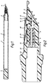
- Figure 1 is an axial cross-section through a pen constructed in accordance with the invention;
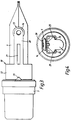
- Figure 2 is an enlarged cross-section of the feed bar and nib assembly;
- Figure 3 is a plan view of the assembly shown in Figure 2;
- Figure 4 is a front end view of the assembly shown in Figure 2;
- Figure 5 is a detailed cross-section of the valve;
- Figure 6 is a side elevation of the grease plug frame;
- Figure 7 is a top plan of the grease plug frame;
- Figure 8 is a bottom plan of the grease plug frame;
- Figure 9 is a section taken along the line A-A in Figure 8;
- Figures 10 to 13 correspond to Figs. 6 to 10 respectively and show an alternative construction for the grease plug frame;
- Figure 14 is a side view of a modified embodiment of the invention;
- Figure 15 is an axial cross-section through the forward end part of the pen of Figure 14; and
- Figure 16 is an axial cross-section through a rear end part of the pen of Figure 14.
- The pen illustrated in Figures 1 to 9 of the drawings is intended to be discarded after the initial ink charge has been completely depleted. It comprises a tubular barrel 1 which also serves to define a
primary reservoir chamber 2 as will become clear, afeed bar 3 fitted to the forward end of the barrel 1 and mounting thepen nib 4, and agrease plug 5 received in the rear end of the barrel immediately behind the column of ink stored in thechamber 2. - The feed bar has an axial bore which is stepped to define three main sections, namely a rear section of large diameter which defines a portion of the primary reservoir chamber, an intermediate section, and a forward section which constitutes a secondary
ink reservoir chamber 6. Accommodated in the intermediate bore section and separating the primary and secondary reservoir chambers is a flow restrictor device consisting of anextruded rod 8 of plastics having one or more capillaries extending longitudinally through the rod, and atubular holder 9 for supporting the rod in the feed bar so that the ink is constrained to flow through the restrictor in passing from the primary to the secondary reservoir chamber. The flow resistance produced by the restrictor is determined by the length of therod 8 and can therefore be adjusted by using longer or shorter lengths of rod. The capacity ofchamber 6 can be very small and is very much less than that of theprimary chamber 2. - An
ink feed channel 10 leads from the secondary reservoir chamber to the upper side of the feed bar, and anannular valve seat 11 extends around the channel for cooperation with avalve member 12 formed by aplug 13. The plug extends through a hole provided in thenib 4 and has an enlargedhead 14 which overlies the nib so that movement of the nib away from the feed bar due to the writing point of the nib being pressed down on a sheet of paper during writing causes theplug 13 to be lifted and thevalve member 12 to be raised from thevalve seat 11 to allow ink to flow out through thefeed channel 10. To encourage the initial ink flow the inner end of the plug is shaped as apiston 15 which acts to draw the ink out of the feed channel with a pump-like action as theplug 13 is lifted. To encourage the ink flow further the domed valve member cooperates with a part-spherical socket formed in the feed bar downstream of the valve seat to define an annular ink duct or channel 16 (Fig. 5) which narrows in width away from the seat so that the capillary forces tend to draw the ink out from the ink feed channel. - The
feed bar 3, and hence the valve seat are formed of relatively hard material, such as polycarbonate and theplug 13 is made of a softer material, e.g. high density polyethylene, so that a good seal will be obtained between the valve member and seat despite any surface irregularities. - The outer surface of the feed bar is provided with a
longitudinal groove 18 extending from the socket towards the free end of the feed bar, this groove tapering in depth and width to define a capillary aiding flow of ink to the writing tip of thenib 4. The nib is slit from its tip to the hole in which theplug 13 is inserted, the slit forming the final part of the ink flow path to the writing tip. The rear end of the nib is supported on a slightly raisedshoulder 20 formed on the feed bar and the nib also rests against the feed bar at the forward end of the latter under the influence of aleaf spring 21. Thus, there is defined between the nib and feed bar a gap which tapers forwardly to encourage by capillary action flow of ink in that direction. For retaining the nib in position the feed bar is formed with alatching projection 23 which engages in ahole 24 in the nib. At a rear end portion of the nib, the sides of the nib are bent to define L-shapedextensions providing stops 24 underlyinglateral abutment shoulders 25 provided on opposite sides of the feed bar (Fig. 4). Thestops 24 engage theshoulders 25 to limit the movement of the nib away from the feed bar to that necessary to open the valve and allow essentially free flow of ink out of thefeed channel 10. In this connection it should be mentioned that the valve is not required to regulate the ink flow rate, this function being performed by therod 8 of the flow restrictor which regulates the flow of ink out of the secondary reservoir chamber by controlling the flow of replacement ink into this chamber from the primary reservoir chamber. - A
second leaf spring 28 acts on thehead 14 ofplug 13 urging the valve member into the closed position. The plug could be fixed to the nib but for ease of manufacturing it is preferred that they should be separate and be acted upon by therespective springs unitary spring component 30 which includes amounting collar 32 surrounding the feed bar and from which projects a finger constituting thespring 28, thespring 21 being formed by a central part stamped out of this finger. Thecollar 32 is notched to receive alocation pip 33 to ensure correct rotational positioning of the spring on the feed bar. - The
grease plug 5 consists of a mass of grease material and a reinforcing frame or cage which is shown in Figures 6 to 9. The cage comprises acentral hub 40 with a pointed end and from which project fourradial fins 41 spaced uniformly around the hub. At the trailing end there is acircular disc 42 withholes 43 which register with the spaces between thefins 41. After the pen barrel 1 is filled with ink the mass of grease is introduced so that it is in contact with the ink surface. The cage is then inserted into the grease so that thedisc 42 covers its outer surface, or so that the cage is completely embedded in the grease. Theholes 43 facilitate the insertion by allowing trapped air to escape. The outer diameter of the cage is less than the inner diameter of the barrel, preferably by an amount to allow a grease layer at least in the order of 0.1mm thick between them. Furthermore, to resist breakup of the grease plug it is preferable for there to be a solid mass of grease extending at least about 5mm forwardly from the front end of the reinforcing cage. - As the ink in the
primary reservoir chamber 2 is used up, the grease plug slides forward along the barrel maintaining contact with the ink. The cage reduces the shear forces within the mass of grease, by confining the shearing forces to a thin layer of grease adjacent the reservoir wall, so that the integrity of the grease mass remains intact despite the large diameter of the barrel and the low viscosity of the agueous ink which may be used in the pen. If thedisc 42 of the cage is positioned to cover the surface of the grease it reduces contact with atmosphere so that hardening or softening of the grease due to drying out and oxidation, which can have deleterious effects on the ability of the grease to follow the ink movement, are essentially precluded. The area of contact is mainly confined to theholes 43 and in extreme cases these could be filled in after insertion of the cage into the grease. - The necessity for the ink in the
primary chamber 2 to pull the grease plug along behind as it flows out of the pen means that the grease plug itself has some restricting effect on the ink flow rate. The flow restrictor can be arranged to make allowance for that resistance so that the required flow rate is obtained. - An alternative form of grease plug reinforcing cage is illustrated in Figures 10-12. It is generally similar in form to the cage of Figs. 6-9 in that it is a unitary member including four uniformly spaced
radial fins 51 and acircular disc 52 at the upper end. The cage has acentral bore 53 extending through thedisc 52, thereby to serve the same purpose of theholes 43 in the first embodiment, and extending along the fins but terminating short of their free lower ends. The bore is of sufficient diameter that it provides direct communication between the inter-fin spaces, which helps to maintain the integrity of the grease plug due to the grease segments filling said spaces being directly connected through the cage. The lower end corners of the fins are radiused to assist in guiding the cage along the reservoir body, and also to encourage bubbles of air to pass out between the grease plug and the reservoir. Also to encourage the passage of air bubbles and minimise friction the fins are reduced in radial width above their lower end portions. Thedisc 52 is formed withnotches 54 in alignment with the fins to prolong the air escape path past the disc. The function and use of the grease cage are the same as described above with respect to Figs. 6-9. - A second embodiment of a pen according to the invention is shown in Figures 14-16. For the most part the pen is essentially the same as that of Figs. 1-5, and the same reference numerals have been used to denote corresponding parts in the drawings of the respective embodiments. The main difference at the forward or writing end of the pen is the addition of a
shroud member 60 which serves to lock thespring component 30 in place on thefeed bar 3, and which also acts to conceal thesprings valve plug 13 whereby they are protected against damage and the overall appearance of the writing tip is enhanced. The shroud member includes acollar 61 which engages with a snap fit in the forward end of the pen barrel 1. The collar also abuts against aflange 62 on the feed bar to hold it against an internal shoulder formed in the barrel, thereby securing the feed bar in the barrel. Anintegral finger portion 63 of the shroud member projects forwardly from thecollar 61 and covers thesprings valve plug 13. Rather than having a mountingcollar 32 as in the first embodiment, thespring component 30 has atail 64 bent around the rear edge of the shroud member and located in a longitudinal groove provided in the outer surface of itscollar 61. Thus, thespring tail 64 is captured and held firmly between theshroud member 60 and the barrel 1, so that the spring component is anchored securely in position. - Turning attention now to the rear end of the pen, it is preferable for the end of the barrel not to be left entirely open as in Figure 1. In the pen of Figs. 14-16 the rear end of the barrel 1 is equipped with a closure member in the form of a
plug 65 pushed with a tight fit into the end of the barrel. Steps need to be taken to avoid a vacuum being created behind thegrease plug 5 as it is moved forwardly due to the ink in the reservoir being used up, since a vacuum would oppose such movement and possibly lead to disintegration of the grease plug. For this purpose an air vent is provided and is formed by alongitudinal groove 66 extending along the inside of the barrel 1 and anotch 67 in the end of the barrel which defines an air port with theplug 65. As shown in Figure 16, the cage reinforcing thegrease plug 5 is completely embedded in the grease. The fact that there is only restricted communication with ambient atmosphere through the narrow vent passage means contact of air with the grease is minimal and hence its adverse affects on the grease are diminished to acceptable levels. It will be appreciated that thefeed bar 3 andshroud member 60, with the other pen parts carried thereby, will be assembled with the barrel 1 following which theprimary reservoir 2 will be filled with ink, thegrease plug 5 and its stabilising cage will be introduced, and finally theplug 65 will be fitted. The pen is intended to be discarded when all the ink has been consumed. Of course, the pen could alternatively be arranged to accept ink cartridges or to be otherwise refillable, but if it is to be filled through the writing end steps would need to be taken to bypass the valve (or to ensure it was open) and bypass theflow restrictor 8 to allow ink to flow into themain reservoir chamber 2 at an acceptable rate during filling operations.
Claims (6)
- A pen having a primary ink reservoir chamber (2), a secondary ink reservoir chamber (6) in fluid communication with said first chamber (2), a nib (4), an ink feed channel (10) for conducting ink from said second chamber (6) to said nib (4) and a valve (12) associated with said ink feed channel (10) to control flow of ink to said nib (4), wherein the valve (12) includes a spring biassed valve member and a cooperating valve seat (11), said valve member having a plug portion (13) and a piston (15) depending from said plug portion and disposed within said channel (10) to draw ink out of said channel as the plug portion is lifted from said valve seat, and in that a flow restrictor (8) is interposed between said first and second ink reservoir chambers.
- A pen according to claim 1, characterized in that a part spherical socket is disposed downstream in the flow path of ink beyond the valve seat (11) and is shaped to cooperate with the profile of the plug portion to define an annular ink chamber (16) which narrows in width away from said seat (11).
- A pen according to claim 1 or claim 2, characterized in that the ink feed channel (10) is defined in a feed bar (3) underlying the nib (4).
- A pen according to claim 3, characterized in that the second ink chamber (6) is defined in the feed bar (3).
- A pen according claim 3 or claim 4, characterized in that the flow restrictor (8) comprises an element of microporous material.
- A pen according to claim 5, characterized in that the flow restrictor (8) is an elongate element supported in the feed bar (3) by a holder (9) isolating the secondary ink chamber (6) from the primary ink chamber (2).
Applications Claiming Priority (3)
| Application Number | Priority Date | Filing Date | Title |
|---|---|---|---|
| GB898911492A GB8911492D0 (en) | 1989-05-18 | 1989-05-18 | Writing instruments |
| GB8911492 | 1989-05-18 | ||
| PCT/US1990/002636 WO1990014964A1 (en) | 1989-05-18 | 1990-05-10 | A pen |
Publications (3)
| Publication Number | Publication Date |
|---|---|
| EP0472660A1 EP0472660A1 (en) | 1992-03-04 |
| EP0472660A4 EP0472660A4 (en) | 1992-11-04 |
| EP0472660B1 true EP0472660B1 (en) | 1997-02-12 |
Family
ID=10656996
Family Applications (1)
| Application Number | Title | Priority Date | Filing Date |
|---|---|---|---|
| EP90909242A Expired - Lifetime EP0472660B1 (en) | 1989-05-18 | 1990-05-10 | A pen |
Country Status (10)
| Country | Link |
|---|---|
| US (1) | US5222824A (en) |
| EP (1) | EP0472660B1 (en) |
| JP (1) | JP3290653B2 (en) |
| AU (1) | AU5819190A (en) |
| BR (1) | BR9007380A (en) |
| CA (1) | CA2054192C (en) |
| DE (1) | DE69029939T2 (en) |
| GB (1) | GB8911492D0 (en) |
| WO (1) | WO1990014964A1 (en) |
| ZA (1) | ZA903454B (en) |
Families Citing this family (10)
| Publication number | Priority date | Publication date | Assignee | Title |
|---|---|---|---|---|
| KR960007401B1 (en) | 1994-06-27 | 1996-05-31 | 신찬 | Multi-unit rotor blade system integrated wind turbine |
| US5874488A (en) * | 1996-07-25 | 1999-02-23 | Bic Corporation | Ink follower compositions |
| GB9909326D0 (en) * | 1999-04-22 | 1999-06-16 | Gillette Co | Pens |
| US6789975B1 (en) | 1999-04-22 | 2004-09-14 | Berol Corporation | Pen |
| GB2359786A (en) | 2000-03-02 | 2001-09-05 | Gillette Co | Ink cartridge with plug and valve |
| FR2806963B3 (en) * | 2000-03-31 | 2002-07-19 | Adtp Ass Departementale Pour L | DEVICE FOR INTERRUPTING THE FLOW OF INK AND CLOSING THE RESERVOIR FOR PEN OR OTHER WRITING OBJECT HAVING A FEATHER AND USING LIQUID INK |
| US6585361B1 (en) * | 2000-10-06 | 2003-07-01 | Seiko Epson Corporation | Multiple-chamber cartridge with varying porous member compression |
| JP4177738B2 (en) * | 2003-09-18 | 2008-11-05 | 株式会社トキワ | Applicator |
| TWM438976U (en) * | 2012-05-31 | 2012-10-11 | yi-shan Lai | Fountain pen with front and back side writing effect |
| CN105620090A (en) * | 2015-12-16 | 2016-06-01 | 刘国西 | Ink pen |
Family Cites Families (6)
| Publication number | Priority date | Publication date | Assignee | Title |
|---|---|---|---|---|
| US70453A (en) * | 1867-11-05 | George rudolph metten | ||
| US881215A (en) * | 1907-11-19 | 1908-03-10 | Ferdinand H Wurdemann | Fountain-pen. |
| GB722177A (en) * | 1949-04-08 | 1955-01-19 | Baltzar Carl Von Platen | Improvements in fountain pens |
| US2669970A (en) * | 1950-05-03 | 1954-02-23 | Gordon Anthony | Fountain pen |
| US4347011A (en) * | 1978-11-17 | 1982-08-31 | Pilot Man-Nen-Hitsu Kabushiki Kaisha | Fountain pen equipped with a resiliency adjustment device |
| US4547090A (en) * | 1983-03-15 | 1985-10-15 | The Gillette Company | Writing instrument with nib operated valve |
-
1989
- 1989-05-18 GB GB898911492A patent/GB8911492D0/en active Pending
-
1990
- 1990-05-07 ZA ZA903454A patent/ZA903454B/en unknown
- 1990-05-10 BR BR909007380A patent/BR9007380A/en not_active Application Discontinuation
- 1990-05-10 EP EP90909242A patent/EP0472660B1/en not_active Expired - Lifetime
- 1990-05-10 JP JP50872290A patent/JP3290653B2/en not_active Expired - Lifetime
- 1990-05-10 CA CA002054192A patent/CA2054192C/en not_active Expired - Fee Related
- 1990-05-10 US US07/820,618 patent/US5222824A/en not_active Expired - Lifetime
- 1990-05-10 WO PCT/US1990/002636 patent/WO1990014964A1/en not_active Ceased
- 1990-05-10 AU AU58191/90A patent/AU5819190A/en not_active Abandoned
- 1990-05-10 DE DE69029939T patent/DE69029939T2/en not_active Expired - Fee Related
Also Published As
| Publication number | Publication date |
|---|---|
| JP3290653B2 (en) | 2002-06-10 |
| JPH07505584A (en) | 1995-06-22 |
| DE69029939D1 (en) | 1997-03-27 |
| CA2054192C (en) | 1995-05-09 |
| GB8911492D0 (en) | 1989-07-05 |
| EP0472660A1 (en) | 1992-03-04 |
| BR9007380A (en) | 1992-04-28 |
| US5222824A (en) | 1993-06-29 |
| EP0472660A4 (en) | 1992-11-04 |
| WO1990014964A1 (en) | 1990-12-13 |
| ZA903454B (en) | 1991-10-30 |
| CA2054192A1 (en) | 1990-11-19 |
| DE69029939T2 (en) | 1997-07-24 |
| AU5819190A (en) | 1991-01-07 |
Similar Documents
| Publication | Publication Date | Title |
|---|---|---|
| US4496258A (en) | Writing pen with space behind nib | |
| US5222824A (en) | Regulated ink flow control system for pen | |
| EP0624483B1 (en) | Writing instrument | |
| JP2679918B2 (en) | Writing implement | |
| EP2014473A1 (en) | Inc cartridge for inkjet printers | |
| US4976564A (en) | Implement for applying liquid | |
| EP0551364B1 (en) | Correction fluid dispenser | |
| JP3664407B2 (en) | Ink containers for writing instruments | |
| AU659675B2 (en) | Marking instruments | |
| JPS61154894A (en) | Ink conduit for tubular pointed writing brush | |
| US6863460B2 (en) | Reservoir pens and ink cartridges therefor | |
| EP1837200A2 (en) | Ink writing device and method for controlling the flow of ink at the tip of the nib | |
| US6575650B1 (en) | Pressure sensed ink-filled pen | |
| US20040170466A1 (en) | Liquid ink writing instrument with a shape memory valve | |
| US4547090A (en) | Writing instrument with nib operated valve | |
| JP2001253194A (en) | Liquid writing instrument | |
| AU4150896A (en) | Marking instrument | |
| JP3179589B2 (en) | Writing implement | |
| JPH0692082A (en) | Writing tool | |
| JP2560925Y2 (en) | Writing implement | |
| JPS6139585Y2 (en) | ||
| KR20200002461A (en) | Writing tool | |
| GB2123351A (en) | Writing instruments | |
| JPS6098683U (en) | Marking pen with valve mechanism | |
| JPH11321175A (en) | fountain pen |
Legal Events
| Date | Code | Title | Description |
|---|---|---|---|
| PUAI | Public reference made under article 153(3) epc to a published international application that has entered the european phase |
Free format text: ORIGINAL CODE: 0009012 |
|
| 17P | Request for examination filed |
Effective date: 19911212 |
|
| AK | Designated contracting states |
Kind code of ref document: A1 Designated state(s): AT BE CH DE DK ES FR GB IT LI LU NL SE |
|
| RBV | Designated contracting states (corrected) |
Designated state(s): DE ES FR GB IT |
|
| A4 | Supplementary search report drawn up and despatched |
Effective date: 19920911 |
|
| AK | Designated contracting states |
Kind code of ref document: A4 Designated state(s): AT BE CH DE DK ES FR GB IT LI LU NL SE |
|
| RIN1 | Information on inventor provided before grant (corrected) |
Inventor name: DIOSSY, CHARLES Inventor name: NICOLL, ROY |
|
| 17Q | First examination report despatched |
Effective date: 19950222 |
|
| GRAG | Despatch of communication of intention to grant |
Free format text: ORIGINAL CODE: EPIDOS AGRA |
|
| GRAH | Despatch of communication of intention to grant a patent |
Free format text: ORIGINAL CODE: EPIDOS IGRA |
|
| GRAH | Despatch of communication of intention to grant a patent |
Free format text: ORIGINAL CODE: EPIDOS IGRA |
|
| GRAA | (expected) grant |
Free format text: ORIGINAL CODE: 0009210 |
|
| AK | Designated contracting states |
Kind code of ref document: B1 Designated state(s): DE ES FR GB IT |
|
| PG25 | Lapsed in a contracting state [announced via postgrant information from national office to epo] |
Ref country code: ES Free format text: THE PATENT HAS BEEN ANNULLED BY A DECISION OF A NATIONAL AUTHORITY Effective date: 19970212 |
|
| REF | Corresponds to: |
Ref document number: 69029939 Country of ref document: DE Date of ref document: 19970327 |
|
| ITF | It: translation for a ep patent filed | ||
| ET | Fr: translation filed | ||
| PLBE | No opposition filed within time limit |
Free format text: ORIGINAL CODE: 0009261 |
|
| STAA | Information on the status of an ep patent application or granted ep patent |
Free format text: STATUS: NO OPPOSITION FILED WITHIN TIME LIMIT |
|
| 26N | No opposition filed | ||
| PGFP | Annual fee paid to national office [announced via postgrant information from national office to epo] |
Ref country code: GB Payment date: 20010509 Year of fee payment: 12 |
|
| PGFP | Annual fee paid to national office [announced via postgrant information from national office to epo] |
Ref country code: FR Payment date: 20010518 Year of fee payment: 12 |
|
| REG | Reference to a national code |
Ref country code: GB Ref legal event code: 732E |
|
| REG | Reference to a national code |
Ref country code: GB Ref legal event code: IF02 |
|
| PG25 | Lapsed in a contracting state [announced via postgrant information from national office to epo] |
Ref country code: GB Free format text: LAPSE BECAUSE OF NON-PAYMENT OF DUE FEES Effective date: 20020510 |
|
| GBPC | Gb: european patent ceased through non-payment of renewal fee |
Effective date: 20020510 |
|
| PG25 | Lapsed in a contracting state [announced via postgrant information from national office to epo] |
Ref country code: FR Free format text: LAPSE BECAUSE OF NON-PAYMENT OF DUE FEES Effective date: 20030131 |
|
| REG | Reference to a national code |
Ref country code: FR Ref legal event code: ST |
|
| PG25 | Lapsed in a contracting state [announced via postgrant information from national office to epo] |
Ref country code: IT Free format text: LAPSE BECAUSE OF NON-PAYMENT OF DUE FEES;WARNING: LAPSES OF ITALIAN PATENTS WITH EFFECTIVE DATE BEFORE 2007 MAY HAVE OCCURRED AT ANY TIME BEFORE 2007. THE CORRECT EFFECTIVE DATE MAY BE DIFFERENT FROM THE ONE RECORDED. Effective date: 20050510 |
|
| PGFP | Annual fee paid to national office [announced via postgrant information from national office to epo] |
Ref country code: DE Payment date: 20080630 Year of fee payment: 19 |
|
| PG25 | Lapsed in a contracting state [announced via postgrant information from national office to epo] |
Ref country code: DE Free format text: LAPSE BECAUSE OF NON-PAYMENT OF DUE FEES Effective date: 20091201 |