EP0472370B1 - Pressure regulating system - Google Patents
Pressure regulating system Download PDFInfo
- Publication number
- EP0472370B1 EP0472370B1 EP19910307553 EP91307553A EP0472370B1 EP 0472370 B1 EP0472370 B1 EP 0472370B1 EP 19910307553 EP19910307553 EP 19910307553 EP 91307553 A EP91307553 A EP 91307553A EP 0472370 B1 EP0472370 B1 EP 0472370B1
- Authority
- EP
- European Patent Office
- Prior art keywords
- chamber
- pressure
- chambers
- valve
- control system
- Prior art date
- Legal status (The legal status is an assumption and is not a legal conclusion. Google has not performed a legal analysis and makes no representation as to the accuracy of the status listed.)
- Expired - Lifetime
Links
- 230000001105 regulatory effect Effects 0.000 title description 5
- 239000012530 fluid Substances 0.000 claims description 37
- 238000004891 communication Methods 0.000 claims description 18
- 238000000034 method Methods 0.000 claims description 4
- 238000010586 diagram Methods 0.000 description 4
- 230000001276 controlling effect Effects 0.000 description 3
- 238000005259 measurement Methods 0.000 description 3
- 239000002699 waste material Substances 0.000 description 3
- 238000010276 construction Methods 0.000 description 2
- 230000003247 decreasing effect Effects 0.000 description 1
- 238000007599 discharging Methods 0.000 description 1
- 238000012423 maintenance Methods 0.000 description 1
- 238000004519 manufacturing process Methods 0.000 description 1
Images


Classifications
-
- G—PHYSICS
- G05—CONTROLLING; REGULATING
- G05D—SYSTEMS FOR CONTROLLING OR REGULATING NON-ELECTRIC VARIABLES
- G05D16/00—Control of fluid pressure
- G05D16/20—Control of fluid pressure characterised by the use of electric means
- G05D16/2006—Control of fluid pressure characterised by the use of electric means with direct action of electric energy on controlling means
- G05D16/2013—Control of fluid pressure characterised by the use of electric means with direct action of electric energy on controlling means using throttling means as controlling means
- G05D16/2026—Control of fluid pressure characterised by the use of electric means with direct action of electric energy on controlling means using throttling means as controlling means with a plurality of throttling means
- G05D16/2033—Control of fluid pressure characterised by the use of electric means with direct action of electric energy on controlling means using throttling means as controlling means with a plurality of throttling means the plurality of throttling means being arranged in series
-
- G—PHYSICS
- G05—CONTROLLING; REGULATING
- G05D—SYSTEMS FOR CONTROLLING OR REGULATING NON-ELECTRIC VARIABLES
- G05D16/00—Control of fluid pressure
- G05D16/20—Control of fluid pressure characterised by the use of electric means
- G05D16/2006—Control of fluid pressure characterised by the use of electric means with direct action of electric energy on controlling means
- G05D16/2013—Control of fluid pressure characterised by the use of electric means with direct action of electric energy on controlling means using throttling means as controlling means
- G05D16/2026—Control of fluid pressure characterised by the use of electric means with direct action of electric energy on controlling means using throttling means as controlling means with a plurality of throttling means
- G05D16/2046—Control of fluid pressure characterised by the use of electric means with direct action of electric energy on controlling means using throttling means as controlling means with a plurality of throttling means the plurality of throttling means being arranged for the control of a single pressure from a plurality of converging pressures
- G05D16/2053—Control of fluid pressure characterised by the use of electric means with direct action of electric energy on controlling means using throttling means as controlling means with a plurality of throttling means the plurality of throttling means being arranged for the control of a single pressure from a plurality of converging pressures the plurality of throttling means comprising only a first throttling means acting on a higher pressure and a second throttling means acting on a lower pressure, e.g. the atmosphere
-
- G—PHYSICS
- G05—CONTROLLING; REGULATING
- G05D—SYSTEMS FOR CONTROLLING OR REGULATING NON-ELECTRIC VARIABLES
- G05D16/00—Control of fluid pressure
- G05D16/20—Control of fluid pressure characterised by the use of electric means
- G05D16/2006—Control of fluid pressure characterised by the use of electric means with direct action of electric energy on controlling means
- G05D16/2013—Control of fluid pressure characterised by the use of electric means with direct action of electric energy on controlling means using throttling means as controlling means
- G05D16/2026—Control of fluid pressure characterised by the use of electric means with direct action of electric energy on controlling means using throttling means as controlling means with a plurality of throttling means
- G05D16/206—Control of fluid pressure characterised by the use of electric means with direct action of electric energy on controlling means using throttling means as controlling means with a plurality of throttling means the plurality of throttling means being arranged for the control of a plurality of diverging pressures from a single pressure
Definitions
- This invention relates to a system which provides a fluid output regulated to a precisely controlled pressure.
- NL-A-8702414 describes a system for regulating the pressure in a gas-filled tank.
- the tank is connected via a valve and adjustable restrictor to a high pressure gas storage tank.
- a fluid pressure control system comprising a first chamber, the pressure in which is to be controlled; a second chamber; valve means for controlling communication between said first and second chambers; and a controller arranged such that, if the pressure in the first chamber differs from a required pressure, said controller is arranged to,
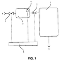
- the fluid pressure control system comprises a larger chamber 1 which can be connected to a smaller chamber 2 through a valve 3. If the pressure in the larger chamber 1 falls below a required level, valve 3 is closed and chamber 2 is raised to a pressure higher than the pressure required in chamber 1, valve 3 is then opened and the higher pressure of chamber 2 is discharged into chamber 1. This discharges a pulse or discrete step of pressure into chamber 1 which increases the pressure in chamber 1 by a relatively small amount because chamber 2 is substantially smaller than chamber 1, and so a series of such pulses or steps has to be delivered to chamber 1 to increase its pressure up to the required level.
- a pressure transducer 4 is positioned to measure the pressure in the smaller chamber 2 but, when valve 3 is open and the pressures in chambers 1 and 2 equalise, the signal from pressure transducer 4 provides a measurement of the pressure in chamber 1.
- the pressure transducer could be situated in chamber 1 to give a direct, continuous measurement of the pressure in chamber 1.
- Chamber 1 is used to supply fluid through an outlet 5 to operate equipment which is not shown in the drawings but which needs a supply the pressure of which can be controllably varied as required.
- equipment might, typically, be another fluid container which is required to deliver fluid at a defined rate and therefore needs a precisely controlled pressure supply.
- Valve 3 is then closed and fluid from a high pressure source 6 is passed into chamber 2 by the opening of a valve 7.
- the pressure in chamber 2 reaches the inlet pressure of source 6, valve 7 is closed and valve 3 is opened, as described above, discharging a pulse or step of pressure into chamber 1.
- the pressurised supply from source 6 is substantially unregulated and its pressure is higher than the pressure required in chamber 1 but, obviously, lower than that which can be tolerated by the mechanical parts of the system and by the transducer.
- the volume of chamber 2 is relatively small in relation to that of chamber 1, the volumes being in the ratio of about 1:200. This relationship determines the size of the pressure step introduced by each pressure pulse.
- a microprocessor control unit 8 shown diagrammatically, which controls the opening and closing of valves 3 and 7 in response to signals received from the pressure transducer 4.
- the output pressure that is the pressure required in chamber 1, is in the range 5 psi to 65 psi, whilst the inlet pressure is about 70 psi.
- the size of chamber 2 is in the ratio 1:200 to the size of chamber 1.
- the volume of the chambers can be calculated from the above given equation to provide a required precision in the pulses delivered from one chamber to the other.
- FIG. 2 there is shown a fluid pressure regulating system similar to that of Figure 1, in that the system comprises a larger chamber 11 which can be connected to a smaller chamber 12 through a valve 13. If the pressure in the larger chamber 11 falls below a required level, valve 13 is closed and the pressure in chamber 12 is raised to a pressure higher than the pressure required in chamber 11, valve 13 is then opened and the higher pressure of chamber 12 is discharged into chamber 11. As with the system of Figure 1, this pulse or step of pressure increases the pressure in the chamber 11 by a relatively small amount and so a series of such pulses or steps has to be delivered to chamber 11 to increase its pressure up to the required level.
- chamber 11 supplies pressurised fluid to an outlet 15 and chamber 12 can receive high pressure fluid from a source 16 through a valve 17.
- the pressure in the larger chamber 11 can be either incremented by small steps or decremented by small steps.
- valve 13 is closed and valve 19 opened to exhaust chamber 12 to waste through an outlet 18 controlled by valve 19.
- Closing valve 19 and opening valve 13 will then allow fluid to flow from chamber 11 into chamber 12 thus reducing the pressure in chamber 11 by a small amount in accordance with the pressure/volume expression set out above in relation to the arrangement of Figure 1.
- Closing valve 13 and opening valve 19 will exhaust chamber 12 through outlet 18 and further small decrements in the pressure in chamber 11 can then be made by first closing valve 19, opening valve 13 to allow fluid to flow from chamber 11 to chamber 12 and closing valve 13 and opening valve 19 to exhaust chamber 12 to waste again through outlet 18.
- the arrangement shown in Figure 2 also has a third chamber 20 which can be connected through a valve 21 to chamber 12.
- This chamber 20 can be used in conjunction with chamber 12 as follows,
- a microprocessor control unit 22 shown diagrammatically, which controls the opening and closing of valves 13, 17, 19 and 21 in response to signals received from the pressure transducer 4.
- Outlet 18 is usually discharged to atmosphere but, in some applications, it may be preferred to exhaust outlet 18 to a vacuum.
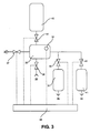
- Figure 3 there is shown a fluid pressure regulating system having the same elements as the systems shown in Figures 1 and 2, in that a larger chamber 31 can be connected to a smaller chamber 32 through a valve 33. If the pressure in the larger chamber 31 falls below a required level, valve 33 is closed and chamber 32 is raised to a pressure which is higher than that required in chamber 31, valve 33 is then opened and the higher pressure of chamber 32 is discharged as a pulse or step into chamber 31. As with the systems of Figures 1 and 2, this pulse of pressure increases the pressure in the larger chamber 31 by a relatively small amount and so a series of such pulses has to be delivered to chamber 31 to increase its pressure up to the required level.
- a pressure transducer 34 is positioned to measure the pressure in the smaller chamber 32 but, when valve 33 is open and the pressures in chambers 31 and 32 equalise, the signal from pressure transducer 34 provides a measurement of the pressure in chamber 31.
- chamber 31 supplies pressurised fluid to an outlet 35 and chamber 32 can receive high pressure fluid from a source 36 through a valve 37.
- Chambers 31 and 32 have the same size relationship as in the system of Figures 1 and 2.
- the system shown in Figure 3 has two fluid outputs.
- the system can provide a second precisely controlled pressure output 45 from a chamber 42 and this can be at a different pressure from the pressure of output 35. If the pressure in the chamber 42 falls below its required level, valve 43 is closed and the pressure in chamber 32 is raised to a pressure which is higher than the pressure required in chamber 42, valve 43 is then opened and the higher pressure of chamber 32 is discharged into chamber 42.
- this pulse or step of pressure increases the pressure in the larger chamber 42 by a relatively small amount and so a series of such pulses has to be delivered to chamber 42 to increase its pressure up to the required level.
- control unit 44 shown diagrammatically, which controls the opening and closing of valves 33, 37, 39, 41 and 43 in response to signals received from the pressure transducer 34.
- the control unit 44 will cause pulses of pressure to be delivered to or removed from these two chambers by interleaving the pulses in whatever the logic of the software of unit 44 deems to be the most efficient manner.
- control units receive information on pressures, volumes and the number of pressure pulses delivered and are able to deduce flow information and can give a read-out of flow rate and total flow.
- the control units are able to select the coarser pulses when a large pressure difference exists and then switch to the finer pulses as the required pressure is neared.
- the control unit can predict the pressure increment or decrement which one pulse will cause, using the pressure/volume relationships set out above, and, when the pressure in the larger chamber is close to the required pressure, it will allow a pulse to be delivered only when the resultant deviation from the required pressure will be a minimum.
- the pressure control systems described here are all simple in construction with few moving parts, mostly just the valves, so that assembly and maintenance is relatively low cost.
- the valves are on-off valves of simple construction.
- the arrangement shown in Figure 3 also has a third chamber 40 which can be connected through a valve 42 to chamber 12.
- This chamber 40 can be used in conjunction with chamber 12 in the same way as described above in relation to Figure 2, to produce coarser or finer control to the production of pulses of pressure.
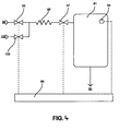
- Figure 4 shows a fluid pressure control system comprising a chamber 81 which is used to supply fluid through an outlet 85 to operate equipment, which is not shown in the drawings, but which needs a supply the pressure of which can be varied as required.
- the pressure in chamber 81 is measured by a transducer 84 which is connected to a controller 88.
- controller 88 opens valve 93 to cause a pulse or step of high pressure fluid from a source 96 to flow through a restrictor 89 into the chamber 81 and, if the pressure in chamber 81 is above the required level, controller 88 opens valve 103 to allow a pulse or step of fluid to flow from chamber 81 to exhaust 106 through the restrictor 89.
- the restrictor 89 varies the rate of flow into and out of the chamber 81 depending on the pressure difference across it.
- an additional valve 97 is arranged between restrictor 89 and chamber 81 and the closing of this valve cuts off flow between restrictor 89 and chamber 81 preventing the decaying flow through the restrictor 89 from causing an overshoot of pressure in the chamber.
- An additional advantage of the arrangement of Figure 4 can be utilised when a large pressure difference below the required pressure exists in chamber 81.
- First valves 93 and 97 can be opened to allow fluid to flow from source 96 to chamber 81 through restrictor 89 until the pressure in chamber 81 nears the required level. Then, provided the restrictor 89 and the system pipework adjacent it have a volume of the order of 1:200 in relation to the volume of chamber 81, the system can be operated in a fashion similar to the operation of the embodiment of Figure 1.
- restrictor 89 and its associated pipework can be supplied with fluid from source 96 with valve 93 open and valve 97 shut.
- valve 93 can be closed and valve 97 opened to allow a pressure pulse or step to be delivered to chamber 81.
- a series of pulses can be delivered to chamber 81 to bring its pressure up to the required level.
- a fluid pressure control system which comprises a chamber 111 which can be connected to a chamber 112 through a valve 113.
- a pressure transducer 114 is situated in chamber 112 and will indicate the pressure in chamber 111 when valve 113 is open and the pressures have equalised. If the pressure in the chamber 111 falls below a required level, valve 113 is closed and chamber 112 is raised to a pressure higher than the pressure required in chamber 111, valve 113 is then opened and the higher pressure of chamber 112 is discharged into chamber 111. This delivers a pulse or discrete step of pressure into chamber 111 which increases the pressure in chamber 111 by an amount which depends on the pressures then in chambers 111 and 112, as these two chambers are of equal volume.
- Chamber 111 is used to supply fluid through an outlet 115 to operate equipment which is not shown in the drawings but which needs a pressure supply which can be controllably varied as required.
- the pressure supply to chamber 112 comes from a pressure source 116 through a valve 117 and two additional chambers 118 and 119 are connected in the system with valves 120, 121.
- the chambers 111, 112, 118 and 119 may all be of equal volume but are not necessarily equal.
- Chambers 112, 118 and 119 are capable of being exhausted to atmosphere through respective valves 122, 128 and 129.
- Chambers 112, 118 and 119 are used to provide a wide variation in the pressure available in chamber 112 for delivery as a pulse or step to chamber 111.
- valves 117, 121 and 120 can be opened and chambers 112, 118 and 119 all filled to the inlet pressure of source 116.
- valve 117 is closed and valve 113 opened, this will produce a large increase in the pressure in chamber 111, depending on the starting pressure in chamber 111 and its relationship to the pressure in source 116.
- chamber 119 alone can be charged to the inlet pressure of source 116 by keeping valve 121 closed. Then by closing valve 117 and opening valve 121, having first exhausted chamber 118, the pressure in chamber 119 can be equilibriated between chambers 119 and 118 producing a pressure in these two chambers lower than the inlet pressure from source 116. By closing valve 121 the pressure in chamber 118 can be equilibriated between chambers 118 and 112 and a pressure pulse or step of much lower pressure than the inlet pressure from source 116 can delivered to chamber 111.
- chamber 119 alone can be charged to the inlet pressure of source 116 by keeping valve 121 closed. Then by closing valve 117 and opening valve 121, having first exhausted chamber 118, the pressure in chamber 119 can be equilibriated between chambers 119 and 118 producing a pressure in these two chambers lower than the inlet pressure from source 116. By then successively exhausting chamber 118 to atmosphere and equilibriating it with chamber 119, an even lower pressure can be produced.
- the chambers thus act as pressure dividers to produce pulses of pressure which are lower than the pressure of source 116.
- the opening and closing of all the valves are controlled by a control system 108 and, because of the multiplicity of chambers and valves, this control system can be preparing a pulse of a desired pressure in chamber 118 whilst still delivering the previous pulse from chamber 112 to chamber 111.
- pulse and “step” are used. These two terms are used synonymously to mean the delivery of a finite amount of fluid into or out of a chamber.
Landscapes
- Physics & Mathematics (AREA)
- Fluid Mechanics (AREA)
- General Physics & Mathematics (AREA)
- Engineering & Computer Science (AREA)
- Automation & Control Theory (AREA)
- Control Of Fluid Pressure (AREA)
Description
- This invention relates to a system which provides a fluid output regulated to a precisely controlled pressure.
- NL-A-8702414 describes a system for regulating the pressure in a gas-filled tank. The tank is connected via a valve and adjustable restrictor to a high pressure gas storage tank.
- According to the present invention, there is provided a fluid pressure control system comprising a first chamber, the pressure in which is to be controlled; a second chamber; valve means for controlling communication between said first and second chambers; and a controller arranged such that, if the pressure in the first chamber differs from a required pressure, said controller is arranged to,
- i) operate said valve means to close off communication between said first and second chambers
- ii) vary the pressure in said second chamber,
- iii) open communication between said first and second chambers to deliver a discrete pressure pulse to said first chamber, and,
- iv) repeat i) to iii) until the pressure in said first chamber reaches a required level.
- i) operating said valve means to close off communication between said first and second chambers;
- ii) varying the pressure in said second chamber;
- iii) opening communication between said first and second chambers to deliver a discrete pressure pulse to said first chamber; and
- iv) repeating i) - iii) until the pressure in said first chamber reaches a required level.
- Embodiments of the invention will now be described, by way of example only, with reference to the accompanying drawings in which,
- Figure 1 is a schematic diagram of a pressure control system constructed in accordance with the present invention,
- Figures 2 and 3 are schematic diagrams similar to Figure 1, each illustrating a system of increasing complexity,
- Figure 4 is a schematic diagram of a further pressure control system, and,
- Figure 5 is a schematic diagram of an alternative pressure control system constructed in accordance with the present invention.
- Referring first to Figure 1, the fluid pressure control system comprises a
larger chamber 1 which can be connected to asmaller chamber 2 through avalve 3. If the pressure in thelarger chamber 1 falls below a required level,valve 3 is closed andchamber 2 is raised to a pressure higher than the pressure required inchamber 1,valve 3 is then opened and the higher pressure ofchamber 2 is discharged intochamber 1. This discharges a pulse or discrete step of pressure intochamber 1 which increases the pressure inchamber 1 by a relatively small amount becausechamber 2 is substantially smaller thanchamber 1, and so a series of such pulses or steps has to be delivered tochamber 1 to increase its pressure up to the required level. - A
pressure transducer 4 is positioned to measure the pressure in thesmaller chamber 2 but, whenvalve 3 is open and the pressures inchambers pressure transducer 4 provides a measurement of the pressure inchamber 1. In an alternative arrangement (not shown) the pressure transducer could be situated inchamber 1 to give a direct, continuous measurement of the pressure inchamber 1. -
Chamber 1 is used to supply fluid through anoutlet 5 to operate equipment which is not shown in the drawings but which needs a supply the pressure of which can be controllably varied as required. Such equipment might, typically, be another fluid container which is required to deliver fluid at a defined rate and therefore needs a precisely controlled pressure supply. When this load requires fluid delivery throughoutlet 5, the pressure inchamber 1 may begin to fall and, withvalve 3 open, this pressure fall will be detected bypressure transducer 4. Valve 3 is then closed and fluid from a high pressure source 6 is passed intochamber 2 by the opening of avalve 7. The pressure inchamber 2 reaches the inlet pressure of source 6,valve 7 is closed andvalve 3 is opened, as described above, discharging a pulse or step of pressure intochamber 1. - The pressurised supply from source 6 is substantially unregulated and its pressure is higher than the pressure required in
chamber 1 but, obviously, lower than that which can be tolerated by the mechanical parts of the system and by the transducer. - The volume of
chamber 2 is relatively small in relation to that ofchamber 1, the volumes being in the ratio of about 1:200. This relationship determines the size of the pressure step introduced by each pressure pulse. Whenvalve 3 is opened and the higher pressure ofchamber 2 is discharged intochamber 1, the pressure increase inchamber 1 is relatively small, being determined by the relationship below which is significantly influenced by the much larger volume ofchamber 1,
- V1 is the volume of
chamber 1 - V2 is the volume of
chamber 2 - P1 is the initial pressure in
chamber 1 - P2 is the inlet pressure introduced into
chamber 2 - P3 is the final common pressure in
chambers - i)
closing valve 3 whenpressure transducer 4 detects a pressure lower than the required level inchamber 1, - ii) opening
valve 7 to allowchamber 2 to reach the inlet pressure, - iii)
closing valve 7, - iv) opening
valve 3 to deliver a small pulse of fluid tochamber 1, - Operation of the system is controlled by a
microprocessor control unit 8, shown diagrammatically, which controls the opening and closing ofvalves pressure transducer 4. Typically, the output pressure, that is the pressure required inchamber 1, is in therange 5 psi to 65 psi, whilst the inlet pressure is about 70 psi. - In this example, the size of
chamber 2 is in the ratio 1:200 to the size ofchamber 1. However, it is not necessary for there to be such a difference in the sizes of the two chambers. The volume of the chambers can be calculated from the above given equation to provide a required precision in the pulses delivered from one chamber to the other. - Referring now to Figure 2, there is shown a fluid pressure regulating system similar to that of Figure 1, in that the system comprises a
larger chamber 11 which can be connected to asmaller chamber 12 through avalve 13. If the pressure in thelarger chamber 11 falls below a required level,valve 13 is closed and the pressure inchamber 12 is raised to a pressure higher than the pressure required inchamber 11,valve 13 is then opened and the higher pressure ofchamber 12 is discharged intochamber 11. As with the system of Figure 1, this pulse or step of pressure increases the pressure in thechamber 11 by a relatively small amount and so a series of such pulses or steps has to be delivered tochamber 11 to increase its pressure up to the required level. Again, as with the system of Figure 1,chamber 11 supplies pressurised fluid to anoutlet 15 andchamber 12 can receive high pressure fluid from asource 16 through avalve 17. - However, in the system of Figure 2 the pressure in the
larger chamber 11 can be either incremented by small steps or decremented by small steps. - If, for any reason, the pressure in
chamber 11 is above the required level, the excess pressure will be detected by thepressure transducer 14 and can be reduced. To do this,valve 13 is closed andvalve 19 opened toexhaust chamber 12 to waste through anoutlet 18 controlled byvalve 19. Closingvalve 19 andopening valve 13 will then allow fluid to flow fromchamber 11 intochamber 12 thus reducing the pressure inchamber 11 by a small amount in accordance with the pressure/volume expression set out above in relation to the arrangement of Figure 1. Closingvalve 13 andopening valve 19 willexhaust chamber 12 throughoutlet 18 and further small decrements in the pressure inchamber 11 can then be made byfirst closing valve 19,opening valve 13 to allow fluid to flow fromchamber 11 tochamber 12 andclosing valve 13 and openingvalve 19 toexhaust chamber 12 to waste again throughoutlet 18. These decremental steps can be performed relatively quickly, for example, once per second, and thus the pressure inchamber 11 can be decreased in a series of small steps down to the required level. - The arrangement shown in Figure 2 also has a
third chamber 20 which can be connected through avalve 21 tochamber 12. Thischamber 20 can be used in conjunction withchamber 12 as follows, - 1) COARSER CONTROL -
Chamber 20 can be used to give coarser control to an increase or decrease of pressure inchamber 11 by allowing larger incremental or decremental steps.
To do this, for example, when an increase in the pressure inchamber 11 is required,chambers valve 21 and filling bothchambers source 16. Valve 17 is then closed andvalve 13 opened to allow the fluid fromchambers chamber 11, so that a larger volume of pressurised fluid than ifchamber 12 had been used alone, will be delivered tochamber 11. By delivering a series of larger pulses or steps of pressurised fluid in this way a low pressure inchamber 11 can be quickly raised to the required level. Similarly,chambers chamber 11 is required.
In both cases (increase and decrease of pressure), as the required pressure inchamber 11 is approached, the system can then switch back from coarser control to usingchamber 12 alone. - 2) FINER CONTROL -
Chamber 20 can be used to give finer control than usingchamber 12 alone, to an increase or decrease in pressure inchamber 11 by allowing smaller incremental or decremental steps.
To do this, when an increase in the pressure inchamber 11 is required,chambers valves valves Valves valve 17 opened to fillchamber 12 fromsource 16.Valve 17 is then closed andvalve 21 opened to allow the fluid fromchamber 12 to flow intochamber 20 so that these twochambers chamber 12 and that inchamber 11. There are then two alternative ways of proceeding,- i)
valve 13 can be opened to allowchambers chamber 11 and a pulse or step of pressure will be injected intochamber 11 which will be at lower pressure than whenchamber 12 was used alone. Usingchamber 20 in this way introduces a change to the expression set out above which now becomes,
- V1 is the volume of
chamber 11 - V2 is the volume of
chamber 12 - V3 is the volume of
chamber 20 - P1 is the initial pressure in
chamber 11 - P2 is the inlet pressure introduced into
chamber 12 - P3 is the initial pressure in
chamber 20 - P4 is the final common pressure in
chambers
- V1 is the volume of
- ii)
valve 21 can be closed so that whenvalve 13 is openedonly chamber 12 communicates withchamber 11 and in this way the volume of fluid available to form the pulse or step injected intochamber 11 will be smaller, giving a smaller increment than with i) above.
chamber 12 to exhaust throughvalve 19, closingvalve 19, and openingvalve 21 to allow the pressures inchambers valve 21 toempty chamber 12 to exhaust again. This can be done several times before opening communication withchamber 11. - i)
- Operation of the system is controlled by a
microprocessor control unit 22, shown diagrammatically, which controls the opening and closing ofvalves pressure transducer 4. -
Outlet 18 is usually discharged to atmosphere but, in some applications, it may be preferred toexhaust outlet 18 to a vacuum. Referring now to Figure 3 there is shown a fluid pressure regulating system having the same elements as the systems shown in Figures 1 and 2, in that alarger chamber 31 can be connected to asmaller chamber 32 through avalve 33. If the pressure in thelarger chamber 31 falls below a required level,valve 33 is closed andchamber 32 is raised to a pressure which is higher than that required inchamber 31,valve 33 is then opened and the higher pressure ofchamber 32 is discharged as a pulse or step intochamber 31. As with the systems of Figures 1 and 2, this pulse of pressure increases the pressure in thelarger chamber 31 by a relatively small amount and so a series of such pulses has to be delivered tochamber 31 to increase its pressure up to the required level. - A
pressure transducer 34 is positioned to measure the pressure in thesmaller chamber 32 but, whenvalve 33 is open and the pressures inchambers pressure transducer 34 provides a measurement of the pressure inchamber 31. - Again, as with the systems of Figures 1 and 2,
chamber 31 supplies pressurised fluid to anoutlet 35 andchamber 32 can receive high pressure fluid from asource 36 through avalve 37.Chambers chamber 31, the system can provide a second precisely controlledpressure output 45 from achamber 42 and this can be at a different pressure from the pressure ofoutput 35. If the pressure in thechamber 42 falls below its required level,valve 43 is closed and the pressure inchamber 32 is raised to a pressure which is higher than the pressure required inchamber 42,valve 43 is then opened and the higher pressure ofchamber 32 is discharged intochamber 42. As with the systems described above, this pulse or step of pressure increases the pressure in thelarger chamber 42 by a relatively small amount and so a series of such pulses has to be delivered tochamber 42 to increase its pressure up to the required level. - Operation of the system is controlled by a
microprocessor control unit 44 shown diagrammatically, which controls the opening and closing ofvalves pressure transducer 34. When there is a demand for or excess of fluid in eitherchamber 31 orchamber 42, thecontrol unit 44 will cause pulses of pressure to be delivered to or removed from these two chambers by interleaving the pulses in whatever the logic of the software ofunit 44 deems to be the most efficient manner. - In the operation of the systems shown in Figures 1, 2 and 3, the control units receive information on pressures, volumes and the number of pressure pulses delivered and are able to deduce flow information and can give a read-out of flow rate and total flow. The control units are able to select the coarser pulses when a large pressure difference exists and then switch to the finer pulses as the required pressure is neared. At any one time the control unit can predict the pressure increment or decrement which one pulse will cause, using the pressure/volume relationships set out above, and, when the pressure in the larger chamber is close to the required pressure, it will allow a pulse to be delivered only when the resultant deviation from the required pressure will be a minimum.
- The pressure control systems described here are all simple in construction with few moving parts, mostly just the valves, so that assembly and maintenance is relatively low cost. In particular, the valves are on-off valves of simple construction.
- The arrangement shown in Figure 3 also has a
third chamber 40 which can be connected through avalve 42 tochamber 12. Thischamber 40 can be used in conjunction withchamber 12 in the same way as described above in relation to Figure 2, to produce coarser or finer control to the production of pulses of pressure. - Figure 4 shows a fluid pressure control system comprising a
chamber 81 which is used to supply fluid through anoutlet 85 to operate equipment, which is not shown in the drawings, but which needs a supply the pressure of which can be varied as required. - The pressure in
chamber 81 is measured by atransducer 84 which is connected to acontroller 88. In controlling the pressure inchamber 81, if this pressure is below the required level,controller 88 opensvalve 93 to cause a pulse or step of high pressure fluid from asource 96 to flow through a restrictor 89 into thechamber 81 and, if the pressure inchamber 81 is above the required level,controller 88 opensvalve 103 to allow a pulse or step of fluid to flow fromchamber 81 to exhaust 106 through therestrictor 89. The restrictor 89 varies the rate of flow into and out of thechamber 81 depending on the pressure difference across it. In the arrangement of Figure 4,anadditional valve 97 is arranged betweenrestrictor 89 andchamber 81 and the closing of this valve cuts off flow betweenrestrictor 89 andchamber 81 preventing the decaying flow through the restrictor 89 from causing an overshoot of pressure in the chamber. - An additional advantage of the arrangement of Figure 4 can be utilised when a large pressure difference below the required pressure exists in
chamber 81.First valves source 96 tochamber 81 throughrestrictor 89 until the pressure inchamber 81 nears the required level. Then, provided the restrictor 89 and the system pipework adjacent it have a volume of the order of 1:200 in relation to the volume ofchamber 81, the system can be operated in a fashion similar to the operation of the embodiment of Figure 1. Thus,restrictor 89 and its associated pipework can be supplied with fluid fromsource 96 withvalve 93 open andvalve 97 shut. Thenvalve 93 can be closed andvalve 97 opened to allow a pressure pulse or step to be delivered tochamber 81. Thus, a series of pulses can be delivered tochamber 81 to bring its pressure up to the required level. - Referring now to Figure 5 a fluid pressure control system is shown which comprises a chamber 111 which can be connected to a
chamber 112 through avalve 113. Apressure transducer 114 is situated inchamber 112 and will indicate the pressure in chamber 111 whenvalve 113 is open and the pressures have equalised. If the pressure in the chamber 111 falls below a required level,valve 113 is closed andchamber 112 is raised to a pressure higher than the pressure required in chamber 111,valve 113 is then opened and the higher pressure ofchamber 112 is discharged into chamber 111. This delivers a pulse or discrete step of pressure into chamber 111 which increases the pressure in chamber 111 by an amount which depends on the pressures then inchambers 111 and 112, as these two chambers are of equal volume. - Chamber 111 is used to supply fluid through an
outlet 115 to operate equipment which is not shown in the drawings but which needs a pressure supply which can be controllably varied as required. - The pressure supply to
chamber 112 comes from apressure source 116 through avalve 117 and twoadditional chambers 118 and 119 are connected in the system withvalves chambers Chambers respective valves Chambers chamber 112 for delivery as a pulse or step to chamber 111. - For example,
valves chambers source 116. Whenvalve 117 is closed andvalve 113 opened, this will produce a large increase in the pressure in chamber 111, depending on the starting pressure in chamber 111 and its relationship to the pressure insource 116. - Alternatively,
chamber 119 alone can be charged to the inlet pressure ofsource 116 by keepingvalve 121 closed. Then by closingvalve 117 andopening valve 121, having first exhausted chamber 118, the pressure inchamber 119 can be equilibriated betweenchambers 119 and 118 producing a pressure in these two chambers lower than the inlet pressure fromsource 116. By closingvalve 121 the pressure in chamber 118 can be equilibriated betweenchambers 118 and 112 and a pressure pulse or step of much lower pressure than the inlet pressure fromsource 116 can delivered to chamber 111. - As a further alternative,
chamber 119 alone can be charged to the inlet pressure ofsource 116 by keepingvalve 121 closed. Then by closingvalve 117 andopening valve 121, having first exhausted chamber 118, the pressure inchamber 119 can be equilibriated betweenchambers 119 and 118 producing a pressure in these two chambers lower than the inlet pressure fromsource 116. By then successively exhausting chamber 118 to atmosphere and equilibriating it withchamber 119, an even lower pressure can be produced. - The chambers thus act as pressure dividers to produce pulses of pressure which are lower than the pressure of
source 116. The opening and closing of all the valves are controlled by acontrol system 108 and, because of the multiplicity of chambers and valves, this control system can be preparing a pulse of a desired pressure in chamber 118 whilst still delivering the previous pulse fromchamber 112 to chamber 111. - In the specification the terms "pulse" and "step" are used. These two terms are used synonymously to mean the delivery of a finite amount of fluid into or out of a chamber.
Claims (11)
- A fluid pressure control system comprising a first chamber (1), the pressure in which is to be controlled; a second chamber (2); valve means (3) for controlling communication between said first and second chambers; and a controller (8) arranged such that, if the pressure in the first chamber differs from a required pressure, said controller is arranged to,i) operate said valve means to close off communication between said first and second chambersii) vary the pressure in said second chamber,iii) open communication between said first and second chambers to deliver a discrete pressure pulse to said first chamber, and,iv) repeat i) to iii) until the pressure in said first chamber reaches a required level.
- A pressure control system as claimed in claim 1, including a third chamber (20) and means (21) for bringing said second (12) and third (20) chambers into communication whereby in ii) variation of the pressure in said second chamber (12) also varies the pressure in said third chamber (20).
- A pressure control system according to Claim 2, whereby after ii) said second chamber is brought into communication with the third chamber so as to vary the pressure in said second chamber and thereby the pressure of said discrete pressure pulse to be delivered to said first chamber.
- A pressure control system according to claim 2 or 3, including means (21) for evacuating said third chamber whereby to reduce its pressure before putting it into communication with said second chamber.
- A pressure control system according to any of the preceding claims, in which two said first chambers (31,41) are provided, one arranged to operate at a different required pressure from the other and both having means for communicating with the second chamber (32).
- A pressure control system according to at least claim 2 or 3, including a fourth chamber (119) capable of being brought into communication with said third chamber.
- A pressure control system according to any of the preceding claims, including pressure measuring means (4) positioned in said second chamber.
- A pressure control system according to any of the preceding claims, wherein the volume of the second chamber is in of the order of 1:200 in relation to the volume of the first chamber.
- A pressure control system according to any of the preceding claims, whereby in ii) the communication remains open until the pressure in the first and second chambers substantially equalises.
- A pressure control system according to any of the preceding claims, wherein the second chamber comprises a restrictor (89) and adjacent system pipework.
- A method of operating a pressure control system to control the fluid pressure in a first chamber, the system comprising a second chamber; valve means for controlling communication between said first and second chambers; the method comprising, if the pressure in the first chamber differs from a required pressure carrying out the steps ofi) operating said valve means to close off communication between said first and second chambers;ii) varying the pressure in said second chamber;iii) opening communication between said first and second chambers to deliver a discrete pressure pulse to said first chamber; andiv) repeating i) - iii) until the pressure in said first chamber reaches a required level.
Applications Claiming Priority (2)
| Application Number | Priority Date | Filing Date | Title |
|---|---|---|---|
| GB9018182 | 1990-08-18 | ||
| GB909018182A GB9018182D0 (en) | 1990-08-18 | 1990-08-18 | Pressure regulating system |
Publications (3)
| Publication Number | Publication Date |
|---|---|
| EP0472370A2 EP0472370A2 (en) | 1992-02-26 |
| EP0472370A3 EP0472370A3 (en) | 1993-06-16 |
| EP0472370B1 true EP0472370B1 (en) | 1996-10-23 |
Family
ID=10680894
Family Applications (1)
| Application Number | Title | Priority Date | Filing Date |
|---|---|---|---|
| EP19910307553 Expired - Lifetime EP0472370B1 (en) | 1990-08-18 | 1991-08-15 | Pressure regulating system |
Country Status (4)
| Country | Link |
|---|---|
| EP (1) | EP0472370B1 (en) |
| JP (1) | JPH0689115A (en) |
| DE (1) | DE69122819T2 (en) |
| GB (1) | GB9018182D0 (en) |
Families Citing this family (3)
| Publication number | Priority date | Publication date | Assignee | Title |
|---|---|---|---|---|
| FR2827682B1 (en) * | 2001-07-20 | 2004-04-02 | Gemplus Card Int | PRESSURE REGULATION BY TRANSFER OF A CALIBRATED GAS VOLUME |
| CN109976402A (en) * | 2019-04-26 | 2019-07-05 | 太原理工大学 | A kind of pressure difference automatic control device and control method |
| JP7535461B2 (en) * | 2021-01-15 | 2024-08-16 | 株式会社堀場エステック | Pressure control system, pressure control method, and pressure control program |
Family Cites Families (2)
| Publication number | Priority date | Publication date | Assignee | Title |
|---|---|---|---|---|
| US4585030A (en) * | 1984-04-06 | 1986-04-29 | Borg-Warner Corporation | Proportional hydraulic solenoid controller |
| NL8702414A (en) * | 1987-10-09 | 1989-05-01 | Stork Brabant Bv | Pressure adjustment in gas tank for rotary printing machine - having tank connected to high capacity gas storage tank with pressure released from either through restriction |
-
1990
- 1990-08-18 GB GB909018182A patent/GB9018182D0/en active Pending
-
1991
- 1991-08-15 EP EP19910307553 patent/EP0472370B1/en not_active Expired - Lifetime
- 1991-08-15 DE DE1991622819 patent/DE69122819T2/en not_active Expired - Fee Related
- 1991-08-16 JP JP3229597A patent/JPH0689115A/en active Pending
Also Published As
| Publication number | Publication date |
|---|---|
| GB9018182D0 (en) | 1990-10-03 |
| EP0472370A3 (en) | 1993-06-16 |
| DE69122819T2 (en) | 1997-04-03 |
| DE69122819D1 (en) | 1996-11-28 |
| EP0472370A2 (en) | 1992-02-26 |
| JPH0689115A (en) | 1994-03-29 |
Similar Documents
| Publication | Publication Date | Title |
|---|---|---|
| US5357996A (en) | Pressure regulating system | |
| US5406988A (en) | Method and apparatus for dispensing compressed gas into a vehicle | |
| EP0332132B1 (en) | Electrohydraulic servo system, especially for injection molding machines | |
| CA1064472A (en) | Multi component liquid mixer with accumulator and throttle control | |
| US5375634A (en) | Variable mass flow rate fluid dispensing control | |
| EP1386083B1 (en) | A control system and a method for controlling an actuator and for optimizing the control by means of sets of valves coupled in parallel | |
| US4321014A (en) | Constant flow pumping apparatus | |
| US5040106A (en) | Apparatus for drawing a pre-selectable quantity of liquid | |
| CN1041351C (en) | Apparatus for delivering metered quanties of a fluid substance | |
| US4450981A (en) | Precision material filling systems | |
| US3847173A (en) | Gas supply system | |
| WO2007103043A2 (en) | Liquid dispense system | |
| CA2092065A1 (en) | Sludge pump | |
| US6695017B1 (en) | Method and apparatus for filling a pressure tank with a fluid | |
| CN105757448B (en) | The accurate subpackage apparatus of gas | |
| US4333486A (en) | Electronic valve controller | |
| EP0472370A2 (en) | Pressure regulating system | |
| CA2086879A1 (en) | Process and apparatus for delivering a metered shot | |
| JPH01302118A (en) | Weighing/supplying apparatus | |
| US5031805A (en) | Processes and device for dosing free-flowing media | |
| KR20090067039A (en) | Gas Valve Arrangement | |
| JP2005127430A (en) | Gas filling device | |
| JP2517181B2 (en) | Liquid dispensing device | |
| JP2662382B2 (en) | Liquid metering device | |
| GB2215629A (en) | Carbonator |
Legal Events
| Date | Code | Title | Description |
|---|---|---|---|
| PUAI | Public reference made under article 153(3) epc to a published international application that has entered the european phase |
Free format text: ORIGINAL CODE: 0009012 |
|
| AK | Designated contracting states |
Kind code of ref document: A2 Designated state(s): DE ES FR GB IT |
|
| PUAL | Search report despatched |
Free format text: ORIGINAL CODE: 0009013 |
|
| AK | Designated contracting states |
Kind code of ref document: A3 Designated state(s): DE ES FR GB IT |
|
| 17P | Request for examination filed |
Effective date: 19931214 |
|
| 17Q | First examination report despatched |
Effective date: 19950306 |
|
| GRAH | Despatch of communication of intention to grant a patent |
Free format text: ORIGINAL CODE: EPIDOS IGRA |
|
| GRAH | Despatch of communication of intention to grant a patent |
Free format text: ORIGINAL CODE: EPIDOS IGRA |
|
| GRAA | (expected) grant |
Free format text: ORIGINAL CODE: 0009210 |
|
| AK | Designated contracting states |
Kind code of ref document: B1 Designated state(s): DE ES FR GB IT |
|
| PG25 | Lapsed in a contracting state [announced via postgrant information from national office to epo] |
Ref country code: IT Free format text: LAPSE BECAUSE OF FAILURE TO SUBMIT A TRANSLATION OF THE DESCRIPTION OR TO PAY THE FEE WITHIN THE PRE;WARNING: LAPSES OF ITALIAN PATENTS WITH EFFECTIVE DATE BEFORE 2007 MAY HAVE OCCURRED AT ANY TIME BEFORE 2007. THE CORRECT EFFECTIVE DATE MAY BE DIFFERENT FROM THE ONE RECORDED.SCRIBED TIME-LIMIT Effective date: 19961023 Ref country code: ES Free format text: THE PATENT HAS BEEN ANNULLED BY A DECISION OF A NATIONAL AUTHORITY Effective date: 19961023 |
|
| REF | Corresponds to: |
Ref document number: 69122819 Country of ref document: DE Date of ref document: 19961128 |
|
| RAP2 | Party data changed (patent owner data changed or rights of a patent transferred) |
Owner name: OXFORD GLYCOSCIENCES (UK) LIMITED |
|
| ET | Fr: translation filed | ||
| PLBE | No opposition filed within time limit |
Free format text: ORIGINAL CODE: 0009261 |
|
| STAA | Information on the status of an ep patent application or granted ep patent |
Free format text: STATUS: NO OPPOSITION FILED WITHIN TIME LIMIT |
|
| 26N | No opposition filed | ||
| PGFP | Annual fee paid to national office [announced via postgrant information from national office to epo] |
Ref country code: DE Payment date: 20000807 Year of fee payment: 10 |
|
| PGFP | Annual fee paid to national office [announced via postgrant information from national office to epo] |
Ref country code: GB Payment date: 20000809 Year of fee payment: 10 |
|
| PGFP | Annual fee paid to national office [announced via postgrant information from national office to epo] |
Ref country code: FR Payment date: 20000811 Year of fee payment: 10 |
|
| PG25 | Lapsed in a contracting state [announced via postgrant information from national office to epo] |
Ref country code: GB Free format text: LAPSE BECAUSE OF NON-PAYMENT OF DUE FEES Effective date: 20010815 |
|
| GBPC | Gb: european patent ceased through non-payment of renewal fee |
Effective date: 20010815 |
|
| PG25 | Lapsed in a contracting state [announced via postgrant information from national office to epo] |
Ref country code: FR Free format text: LAPSE BECAUSE OF NON-PAYMENT OF DUE FEES Effective date: 20020430 |
|
| PG25 | Lapsed in a contracting state [announced via postgrant information from national office to epo] |
Ref country code: DE Free format text: LAPSE BECAUSE OF NON-PAYMENT OF DUE FEES Effective date: 20020501 |
|
| REG | Reference to a national code |
Ref country code: FR Ref legal event code: ST |