EP0472343A1 - Disc recording and reproducing apparatus - Google Patents
Disc recording and reproducing apparatus Download PDFInfo
- Publication number
- EP0472343A1 EP0472343A1 EP91307446A EP91307446A EP0472343A1 EP 0472343 A1 EP0472343 A1 EP 0472343A1 EP 91307446 A EP91307446 A EP 91307446A EP 91307446 A EP91307446 A EP 91307446A EP 0472343 A1 EP0472343 A1 EP 0472343A1
- Authority
- EP
- European Patent Office
- Prior art keywords
- data
- recording
- cluster
- disc
- digital data
- Prior art date
- Legal status (The legal status is an assumption and is not a legal conclusion. Google has not performed a legal analysis and makes no representation as to the accuracy of the status listed.)
- Granted
Links
- 230000003287 optical effect Effects 0.000 abstract description 27
- 238000007906 compression Methods 0.000 description 19
- 230000006835 compression Effects 0.000 description 19
- 230000005236 sound signal Effects 0.000 description 13
- 238000005070 sampling Methods 0.000 description 10
- 238000013144 data compression Methods 0.000 description 7
- 238000000034 method Methods 0.000 description 6
- 230000000694 effects Effects 0.000 description 5
- 230000002411 adverse Effects 0.000 description 3
- 230000006870 function Effects 0.000 description 3
- 230000008569 process Effects 0.000 description 3
- 230000008901 benefit Effects 0.000 description 2
- 230000010287 polarization Effects 0.000 description 2
- 238000013139 quantization Methods 0.000 description 2
- 230000003044 adaptive effect Effects 0.000 description 1
- 230000008859 change Effects 0.000 description 1
- 238000006243 chemical reaction Methods 0.000 description 1
- 238000010586 diagram Methods 0.000 description 1
- 239000000284 extract Substances 0.000 description 1
- 230000007257 malfunction Effects 0.000 description 1
- 230000008707 rearrangement Effects 0.000 description 1
Images


Classifications
-
- G—PHYSICS
- G11—INFORMATION STORAGE
- G11B—INFORMATION STORAGE BASED ON RELATIVE MOVEMENT BETWEEN RECORD CARRIER AND TRANSDUCER
- G11B7/00—Recording or reproducing by optical means, e.g. recording using a thermal beam of optical radiation by modifying optical properties or the physical structure, reproducing using an optical beam at lower power by sensing optical properties; Record carriers therefor
-
- G—PHYSICS
- G11—INFORMATION STORAGE
- G11B—INFORMATION STORAGE BASED ON RELATIVE MOVEMENT BETWEEN RECORD CARRIER AND TRANSDUCER
- G11B20/00—Signal processing not specific to the method of recording or reproducing; Circuits therefor
- G11B20/00007—Time or data compression or expansion
-
- G—PHYSICS
- G11—INFORMATION STORAGE
- G11B—INFORMATION STORAGE BASED ON RELATIVE MOVEMENT BETWEEN RECORD CARRIER AND TRANSDUCER
- G11B20/00—Signal processing not specific to the method of recording or reproducing; Circuits therefor
- G11B20/10—Digital recording or reproducing
- G11B20/10527—Audio or video recording; Data buffering arrangements
-
- G—PHYSICS
- G11—INFORMATION STORAGE
- G11B—INFORMATION STORAGE BASED ON RELATIVE MOVEMENT BETWEEN RECORD CARRIER AND TRANSDUCER
- G11B27/00—Editing; Indexing; Addressing; Timing or synchronising; Monitoring; Measuring tape travel
- G11B27/005—Reproducing at a different information rate from the information rate of recording
-
- G—PHYSICS
- G11—INFORMATION STORAGE
- G11B—INFORMATION STORAGE BASED ON RELATIVE MOVEMENT BETWEEN RECORD CARRIER AND TRANSDUCER
- G11B27/00—Editing; Indexing; Addressing; Timing or synchronising; Monitoring; Measuring tape travel
- G11B27/10—Indexing; Addressing; Timing or synchronising; Measuring tape travel
- G11B27/19—Indexing; Addressing; Timing or synchronising; Measuring tape travel by using information detectable on the record carrier
- G11B27/28—Indexing; Addressing; Timing or synchronising; Measuring tape travel by using information detectable on the record carrier by using information signals recorded by the same method as the main recording
- G11B27/30—Indexing; Addressing; Timing or synchronising; Measuring tape travel by using information detectable on the record carrier by using information signals recorded by the same method as the main recording on the same track as the main recording
- G11B27/3027—Indexing; Addressing; Timing or synchronising; Measuring tape travel by using information detectable on the record carrier by using information signals recorded by the same method as the main recording on the same track as the main recording used signal is digitally coded
-
- G—PHYSICS
- G11—INFORMATION STORAGE
- G11B—INFORMATION STORAGE BASED ON RELATIVE MOVEMENT BETWEEN RECORD CARRIER AND TRANSDUCER
- G11B27/00—Editing; Indexing; Addressing; Timing or synchronising; Monitoring; Measuring tape travel
- G11B27/10—Indexing; Addressing; Timing or synchronising; Measuring tape travel
- G11B27/34—Indicating arrangements
-
- G—PHYSICS
- G11—INFORMATION STORAGE
- G11B—INFORMATION STORAGE BASED ON RELATIVE MOVEMENT BETWEEN RECORD CARRIER AND TRANSDUCER
- G11B7/00—Recording or reproducing by optical means, e.g. recording using a thermal beam of optical radiation by modifying optical properties or the physical structure, reproducing using an optical beam at lower power by sensing optical properties; Record carriers therefor
- G11B7/007—Arrangement of the information on the record carrier, e.g. form of tracks, actual track shape, e.g. wobbled, or cross-section, e.g. v-shaped; Sequential information structures, e.g. sectoring or header formats within a track
- G11B7/013—Arrangement of the information on the record carrier, e.g. form of tracks, actual track shape, e.g. wobbled, or cross-section, e.g. v-shaped; Sequential information structures, e.g. sectoring or header formats within a track for discrete information, i.e. where each information unit is stored in a distinct discrete location, e.g. digital information formats within a data block or sector
-
- G—PHYSICS
- G11—INFORMATION STORAGE
- G11B—INFORMATION STORAGE BASED ON RELATIVE MOVEMENT BETWEEN RECORD CARRIER AND TRANSDUCER
- G11B20/00—Signal processing not specific to the method of recording or reproducing; Circuits therefor
- G11B20/10—Digital recording or reproducing
- G11B20/12—Formatting, e.g. arrangement of data block or words on the record carriers
- G11B2020/1264—Formatting, e.g. arrangement of data block or words on the record carriers wherein the formatting concerns a specific kind of data
- G11B2020/1265—Control data, system data or management information, i.e. data used to access or process user data
- G11B2020/1277—Control data, system data or management information, i.e. data used to access or process user data for managing gaps between two recordings, e.g. control data in linking areas, run-in or run-out fields, guard or buffer zones
-
- G—PHYSICS
- G11—INFORMATION STORAGE
- G11B—INFORMATION STORAGE BASED ON RELATIVE MOVEMENT BETWEEN RECORD CARRIER AND TRANSDUCER
- G11B2220/00—Record carriers by type
- G11B2220/20—Disc-shaped record carriers
- G11B2220/25—Disc-shaped record carriers characterised in that the disc is based on a specific recording technology
- G11B2220/2525—Magneto-optical [MO] discs
-
- G—PHYSICS
- G11—INFORMATION STORAGE
- G11B—INFORMATION STORAGE BASED ON RELATIVE MOVEMENT BETWEEN RECORD CARRIER AND TRANSDUCER
- G11B2220/00—Record carriers by type
- G11B2220/20—Disc-shaped record carriers
- G11B2220/25—Disc-shaped record carriers characterised in that the disc is based on a specific recording technology
- G11B2220/2537—Optical discs
- G11B2220/2545—CDs
- G11B2220/255—CD-I, i.e. CD-interactive
-
- G—PHYSICS
- G11—INFORMATION STORAGE
- G11B—INFORMATION STORAGE BASED ON RELATIVE MOVEMENT BETWEEN RECORD CARRIER AND TRANSDUCER
- G11B27/00—Editing; Indexing; Addressing; Timing or synchronising; Monitoring; Measuring tape travel
- G11B27/10—Indexing; Addressing; Timing or synchronising; Measuring tape travel
- G11B27/19—Indexing; Addressing; Timing or synchronising; Measuring tape travel by using information detectable on the record carrier
- G11B27/28—Indexing; Addressing; Timing or synchronising; Measuring tape travel by using information detectable on the record carrier by using information signals recorded by the same method as the main recording
- G11B27/30—Indexing; Addressing; Timing or synchronising; Measuring tape travel by using information detectable on the record carrier by using information signals recorded by the same method as the main recording on the same track as the main recording
- G11B27/3027—Indexing; Addressing; Timing or synchronising; Measuring tape travel by using information detectable on the record carrier by using information signals recorded by the same method as the main recording on the same track as the main recording used signal is digitally coded
- G11B27/3063—Subcodes
Definitions
- This invention relates to disc recording apparatus and to disc reproducing apparatus particularly, but not exclusively, for optically recorded digital data.
- An optical disc may have a recording capacity larger by two or three orders than that of a magnetic disc, while enabling accessing at a higher speed than that for a tape recording medium.
- An optical disc also has the advantage of contactless data recording and reproduction, so has good durability.
- a well known form of optical disc is the so-called compact disc (CD).
- a CD with a diameter of 12 cm and a CD with a diameter of 8 cm have been proposed.
- a disc diameter of 12 cm the recording/reproducing apparatus is too bulky to be readily portable. Therefore, a disc 8 cm or less in diameter would be preferred.
- the playback time (recording time) of a disc 8 cm in diameter is 20 to 22 minutes at most, meaning that a symphony, for example, cannot be recorded on one disc side.
- a playback time of 74 minutes or longer, which is approximately equal to that of a 12 cm CD is preferred.
- recording by the user is not feasible.
- a contactless type optical pick-up device is vulnerable to mechanical vibrations and subject to detracking or defocusing. Thus, when the apparatus is to be portable, some positive measures need to be taken to prevent adverse effects of detracking or defocusing on the reproducing operation.
- CD-MO format a format employing a recordable magneto-optical disc
- CD-DA format an extension format of the abovementioned standard CD format
- the optical pick-up device is similarly subject to detracking or defocusing due to mechanical vibration, such that again positive measures need to be taken to prevent any adverse effects thereof on the recording/reproducing operation.
- the levels A to C as shown in the following Table 1 are prescribed as modes for recording/reproducing bit-compressed digital audio signals.
- the disc is rotationally driven at the same linear velocity as that for the standard CD-DA format, so that continuous audio compressed data are reproduced at a rate of one unit to n recorded units on the disc, where n is a figure corresponding to the playback time or the bit compression rate of data, and is equal to 4 with the level B stereo mode.
- This unit is termed a block or sector, which is made up of 98 frames and has a period of 1/75 second. Therefore, with this level B stereo mode, a data string in which one of 4 sectors is an audio sector, such as: S D D D S D D D ... where S is an audio sector and D is another sector or sectors, is recorded on a sector-by-sector basis on the disc.
- data of the audio sector S and data of the data sector D are arranged in a scrambled fashion in the recording sectors on the disc.
- the other data sectors D may, for example, be video or computer data.
- a data string in which 4-channel audio sectors S1 to S4 are cyclically arranged; that is a data string: S1 S2 S3 S4 S1 S2 S3 S4 ... is encoded and recorded on the disc.
- the above-mentioned 4-channel audio signals are linked sequentially beginning at the first channel and terminating at the fourth channel. More specifically, channel 1 data corresponding to the audio sector S1 are reproduced from the innermost to the outermost areas of the disc. Channel 2 data corresponding to the audio sector S2 are reproduced from the innermost to the outermost areas of the disc. Channel 3 data corresponding to the next audio sector S3 are reproduced from the innermost to the outermost areas of the disc. Finally, channel 4 data corresponding to the audio sector S4 are reproduced from the innermost to the outermost areas of the disc to enable data reproduction for a continuous 4-fold time duration.
- a disc recording apparatus for recording time compressed digital data on a disc-shaped recording medium, the apparatus comprising: storage means for temporarily storing said digital data; and means for arranging said digital data read out from said storage means into a plurality of clusters at an interval of a predetermined number of sectors, annexing cluster-linking sectors at linking portions of each of said clusters, each of said cluster-linking sectors being longer than an interleaving length for said digital data, subsequently processing the digital data within each of said clusters by interleaving, and recording interleaved data on said medium.
- a disc reproducing apparatus for reproducing record data continuously recorded on a disc-shaped recording medium, the apparatus comprising: reproducing means for reproducing record data which record data are time compressed digital data previously arranged into a plurality of clusters at an interval of a predetermined number of sectors, to which have been added cluster-linking sectors so that a cluster-linking portion is of a length longer than an interleaving length for said digital data, and which have been recorded on said medium after interleaving said digital data in said cluster; storage means for deinterleaving playback data from the apparatus and storing digital data from which said cluster linking sectors have been removed; time expanding means supplied with said digital data intermittently read out from said storage means and outputting said digital data as time-expanded output signals; and control means for effecting writing control of said storage means so that, when an amount of said digital data stored in said storage means becomes lower than a predetermined amount of data, said record data are started to be reproduced to write the reproduced data in said storage means so that said predetermined
- a disc reproducing apparatus comprising reproducing means for reproducing a disc-shaped recording medium on which are recorded compressed digital data arranged into a plurality of clusters at an interval of a predetermined number of sectors, provided with cluster-linking sectors each longer than an interleaving length at linking portions of each of said clusters, and subsequently interleaved, storage means for transiently storing playback data from said reproducing means, and control means causing said playback data to be written when the data volume of said playback data stored in said storage means is less than a predetermined volume, so that a read-out space in excess of a predetermined data volume is maintained in said storage means.
- the storage means minimizes changes in the recording/reproducing operation due to the difference in the compression modes, while absorbing fluctuations in the recording/reproducing operation caused by mechanical vibration.
- record data are written in said storage means at a data transfer rate conforming to the prevailing compression modes and are read out intermittently, that is, in a burst fashion, at a predetermined standard data transfer rate, so as to be recorded on the disc-shaped recording medium.
- reproduction data are reproduced intermittently, that is in a burst fashion, from the disc-shaped recording medium at the predetermined standard data transfer rate and are written on said storage means so as to be read out at a data transfer rate conforming to the prevailing compression mode.
- Recording on the disc-shaped recording medium is made on a cluster-by-cluster basis. Since a cluster-linking sector longer than an interleaving length is provided between adjoining clusters, recording may be made so as to be inclusive of the cluster-linking sectors to eliminate the effects of interleaving on neighbouring clusters.
- recording may be performed independently on a cluster-by-cluster basis, without the necessity of taking the effects of interleaving on other clusters into account, so that processing as well as re-recording in the case of a recording failure may be facilitated.
- drop-out of playback data by the cluster-linking sectors may be buffered by provision of a memory means for temporary storage of playback data, so as to enable continuous playback data to be obtained from the memory means.
- the present invention is preferably applied to an apparatus for recording and reproducing bit compressed data (time compressed data).
- a magneto-optical disc 2 rotationally driven by a spindle motor 1 is employed as a recording medium. While a laser light is irradiated by an optical head 3 on the disc 2, a modulating magnetic field corresponding to recording data is applied by a magnetic head 4 to the disc 2 for recording data along a recording track of the disc 2. On the other hand, the recording track of the disc 2 is traced with a laser light by the optical head 3 for photomagnetically reproducing the recorded data.
- the optical head 3 comprises a laser light source, such as a laser diode, optical components, such as a collimator lens, an objective lens, a polarization beam splitter or a cylindrical lens, and a split photodetector, although these device are not shown, and is arranged to face the magnetic head 4 with the disc 2 in-between.
- the optical head 3 irradiates a laser light on a target track on the disc 2 for recording data by thermomagnetic recording.
- the modulating magnetic field corresponding to the recording data is applied to the target track by the magnetic head 4, which is driven by a head driving circuit 16 of the recording system which will be explained subsequently.
- the optical head 3 detects a laser light irradiated on and reflected by the target track for detecting the focusing error by a so-called astigmatic method, as well as detecting the tracking error by a so-called push-pull method.
- the optical head 3 detects the difference of a polarization angle (Kerr rotation angle) of the reflected laser light from the target track to produce playback signals.
- the output of the optical head 3 is supplied to an RF circuit 5.
- the RF circuit 5 extracts the focusing error signal and the tracking error signal from the output of the optical head 3 and transmits the extracted signals to a servo control circuit 6 while converting the reproduced signals into corresponding binary signals and supplying the binary signals to a decoder 21 of the reproducing system, which will be explained subsequently.
- the servo control circuit 6 comprises a focusing servo circuit, a tracking servo circuit, a spindle motor servo control circuit and a thread servo control circuit, although these circuits are not shown.
- the focusing servo control circuit executes focusing control of an optical system of the optical head 3 so that the focusing error signal will be reduced to zero.
- the tracking servo control circuit executes tracking control of the optical system of the optical head 3 so that the tracking error signal will be reduced to zero.
- the spindle motor servo control circuit controls the motor 1 for rotationally driving the disc 2 at a predetermined rotational velocity, such as at a constant linear velocity.
- the thread servo control circuit causes the optical head 3 and the magnetic head 4 to be moved to a target track position on the disc 2 designated by the system controller 7.
- the system controller 7 controls the recording system and the reproducing system with the operating mode designated by operating input information from the key unit 8.
- the system controller 7 supervises, on the basis of a sector-by-sector address information reproduced from the recording track of the disc 2 by the header time or sub-Q data, the recording position as well as the reproducing position on the recording track traced by the optical head 3 and the magnetic head 4.
- the system controller 7 causes a bit compression mode to be displayed on the display 9 on the basis of bit compression mode data in the reproduced data obtained from the RF circuit 5 by means of a reproducing system as later described, or of bit compression mode data in an adaptive differential PCM (ADPCM) encoder 13 switchingly selected by the key unit 8.
- ADPCM adaptive differential PCM
- the system controller 7 also causes the playback time to be displayed on the display 9 on the basis of a data compression ratio and the reproducing position data on the recording track in the bit compression mode.
- the sector-by-sector address information (absolute time information), reproduced from the recording track of the disc 2 with the head time or sub-Q data, is multiplied by a reciprocal of the data compression ratio in the bit compression mode (4 in the case of 1/4 compression) to find an actual time information for display on the display 9. It is noted that, if absolute time information has been recorded (preformatted) on a recording track of a magneto-optical disc, the preformatted absolute time information may be read during recording and multiplied by the reciprocal of the data compression ratio to cause display of the current position in the form of the actual recording time.
- the apparatus also comprises an A/D converter 12 to which an analogue audio signal A IN is supplied from an input terminal 10 by way of a low-pass filter 11.
- the A/D converter 12 quantizes the audio signal A IN .
- the digital audio data obtained at the A/D converter 12 is transmitted to the ADPCM encoder 13.
- the ADPCM encoder 13 processes the standard transfer rate digital audio data quantized from the audio signal A IN by the A/D converter 12 by a data compressing operation in conformity with the various modes in the CD-I system shown in Table 1, and has its operating mode designated by the system controller 7.
- the digital audio data are processed into compressed data (ADPCM) audio data) having a sampling frequency of 37.8 kHz, with the number of bits per sample equal to 4 before being supplied to a memory 14.
- the data transfer rate with the B-level stereo mode is reduced to 1/4 of the standard data transfer rate of 75 sectors/second, or 18.75 sectors/second.
- the sampling frequency of the A/D converter 12 is fixed at the sampling frequency of the standard CD-DA format, or 44.1 kHz, and that, in the ADPCM encoder 13, bit compression from 16 bits to 4 bits is performed after conversion of the sampling rate in conformity with the compression mode, for example, from 44.1 kHz to 37.8 kHz for level B.
- the sampling frequency of the A/D converter 12 itself may be switchingly controlled as a function of the compression modes.
- the cut-off frequency of the low-pass filter 11 is also switchingly controlled as a function of the switchingly controlled sampling frequencies of the A/D converter 12. That is, the sampling frequency of the A/D converter 12 and the cut-off frequency of the low-pass filter 11 may be simultaneously controlled in dependence upon the compression modes.
- the memory 14 is used as a buffer memory in which data writing and read-out are controlled by the system controller 7, and which transiently stores ADPCM audio data supplied from the ADPCM encoder 13 for recording on the disc 1 as the occasion may demand. That is, in the B-level stereo mode, the compressed audio data supplied from the ADPCM encoder 13 has its transfer rate reduced to 1/4 of the standard data transfer rate of 75 sectors/second, or to 18.75 sectors/second, these compressed data being continuously written in the memory 14. Although it suffices to record the compressed data (ADPCM data) at a rate of every 4 sectors, as explained above, it is practically impossible to record the data at this rate in view of the interleaving operation, and hence the sectors are recorded continuously as later explained.
- the overall data transfer rate of the data read out and recorded in this way, inclusive of the non-recording period, is a lower rate of 18.75 sectors/second.
- an instantaneous data transfer rate within the time of the burst-like recording operation is equal to the above-mentioned standard rate of 75 sectors/second. Therefore, if the rotational velocity of the disc is the same as that of the standard CD-DA format, that is, a constant linear velocity, recording is made at the same recording density and with the same recording pattern as those of the CD-DA format.
- the ADPCM audio data read out from memory 14 in a burst fashion at the transfer rate of 75 sectors/second, that is, the record data, is supplied to an encoder 15.
- a data string supplied from the memory 14 to the encoder 15 a data unit continuously recorded with each recording is composed of a plurality of, for example 32 sectors, and a few cluster-linking sectors arrayed before and after the cluster.
- the cluster-linking sector has a length longer than the interleaving length at the encoder 13, so that, even when the sector undergoes interleaving, data of other clusters remain unaffected. Details of the recording on the cluster-by-cluster basis will be discussed later referring to Figure 2.
- the encoder 15 processes the record data supplied in a burst fashion from the memory 14 with an error correcting coding operation, such as by parity addition or interleaving, or 8-to-14 modulation (EFM).
- EFM 8-to-14 modulation
- the magnetic head 4 To the head driving circuit 16 is connected the magnetic head 4 and drives it to apply a modulating magnetic field conforming to the record data to the disc 2.
- the system controller 7 performs writing and read-out control for the memory 14 and, based on the armory control, performs a disc recording position control so that the above-mentioned record data read out in a burst fashion from memory 14 will be recorded continuously on the recording track of the disc 2.
- the recording position control the record position on the disc 1 of the record data read out in a burst fashion from the memory 14 is supervised by the system controller 7, and controls signals designating the record position on the recording track of the disc 2 are supplied to the servo control circuit 6.
- the reproducing system reproduces the record data continuously recorded by the above-described recording system on the recording track of the disc 2, and is provided with the decoder 21, to which is supplied a playback output, which has been generated by the optical head 3 tracing the recording track on the disc 3 with a laser light and converted into binary format signals by the RF circuit 5.
- the decoder 21 is associated with the encoder 15 in the above-described recording system, and processes the playback output, converted into the binary format signals by the RF circuit 5, with the above-mentioned decoding for error correction and EFM decoding, and reproduces the above-mentioned B level stereo mode ADPCM audio data at a transfer rate of 75 sectors/second, which is faster than the normal transfer rate in the above-mentioned B level stereo mode.
- the reproduced data, produced by the decoder 21, are supplied to a memory 22.
- the memory 22 has its data writing and read-out controlled by the system controller 7 so that the playback data supplied from decoder 21 at a transfer rate of 75 sectors/second are sequentially written at the transfer rate of 75 sectors/second. Also the playback data intermittently written at the transfer rate of 75 sectors/second in the memory 22 are continuously read out therefrom at the regular B-level stereo mode of 18.75 sectors/second.
- the system controller 7 also performs a memory control of writing the reproduced data in the memory 22 at the transfer rate of 75 sectors/second, continuously reading out the playback data from the memory 22 at the transfer rate of 18.75 sectors/second, and stopping writing to prevent overflow of data stored in the memory 22.
- the system controller 7 performs, besides the above-mentioned writing and read-out control for the memory 22, a reproducing position control for the recording track of the disc 2, in such a manner that the playback data written by the above-mentioned memory control in the memory 22 are written therein continuously.
- the reproducing position control is performed by supervising a reproducing position on the disc 1 of the above-mentioned playback data read out in a burst fashion from the memory 22 by the system controller 7, and by supplying a control signal designating the reproducing position on the recording track of the disc 2 to the servo control circuit 6.
- the B-level stereo mode ADPCM audio data obtained as playback data read out continuously from the memory 22 at a transfer rate of 18.75 sectors/second, are supplied to the ADPCM decoder 23.
- the ADPCM decoder 23 is associated with the ADPCM encoder 13 of the recording system.
- the ADPCM decoder 23 has its operating mode designated by the system controller 7. With the present apparatus, the B-level stereo mode ADPCM audio data are expanded by a factor of 4 for reproducing the CD-DA mode digital audio data.
- the reproduced digital audio data are transmitted by the ADPCM decoder 23 to a D/A converter 24.
- the D/A converter 24 causes the digital audio data supplied from the ADPCM decoder 23 to be converted into an analogue audio signal A OUT which is supplied via a low-pass filter 25 at an output terminal 26.
- the reproducing system of this apparatus is provided with a digital outputting function so that the digital audio data at the output of the ADPCM decoder 23 is outputted at a data output terminal 28 via a digital output encoder 27 as a digital audio signal D OUT .
- the disc 2 employed in the above-described apparatus preferably has a recording space of longer than 60 minutes and up to 74 minutes for stereo audio signals. With the data compression rate of 1/4 as in the above-mentioned B level mode, a recording capacity of approximately 130 M bytes is necessary. For a portable or pocketable size of apparatus, it is preferred to use a disc outside diameter of 8 cm or less. In addition, a track pitch of 1.6 ⁇ m and a linear velocity of 1.2 to 1.4 m/second, similar to those of a compact disc, are preferred.
- the disc outside diameter may be 64 mm
- the outside diameter of a data recording region may be 61 mm
- the inside diameter of the data recording region may be 32 mm
- the inside diameter of the lead-in region may be 30 mm
- a centre hole diameter may be 10 mm.
- the inside and outside diameters of the disc recording region for enabling recording and/or reproduction for 72 to 76 minutes with the above-mentioned 1/4 data compression mode may be suitably selected within the range of the outside diameter of 60 to 62 mm for the inside diameter of 32 mm and within the range of the outside diameter of 71 to 73 mm for the inside diameter of 50 mm.
- the record data that is data read out from the memory 14, is arranged into a cluster at an interval of a predetermined number of, for example 32, sectors or blocks, and several cluster-linking sectors are arrayed between adjoining clusters.
- each cluster C consists of 32 sectors or blocks B0 to B31, and five linking sectors L1 to L5 are arranged between these clusters C for linking the adjoining clusters.
- a cluster such as a K'th cluster C K
- the 32 sectors B0 to B31 of the cluster C K , and the linking clusters ahead of and following the cluster C K namely the three sectors L3 to L5 towards the cluster C K-1 , ( run- in blocks ) and the three blocks L1 to L3 towards the cluster C K+1 , making a total of 38 sectors, are recorded as one unit.
- the 38-sector record data are transmitted from the memory 14 to the encoder 15 where interleaving is carried out from data rearrangement over a distance of up to 108 frames corresponding to ca. 1.1 sector.
- the data within the cluster C K safely contained within a range of from the run-in blocks L3 to L5 to the run-out blocks L1 to L3 without affecting the remaining clusters c K-1 or C K+1 .
- dummy data such as 0, are arrayed in the linking sectors L1 to L5 to avoid adverse effects which interleaving might have on the data per se.
- three sectors L3 to L5 of the five linking sectors L1 to L5 between the current cluster and the next cluster C K+1 are used as the run-in blocks, so that the sector L3 is recorded superfluously.
- the sector L3 of the run-in block or the sector L3 of the run-out block may be omitted.
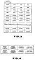
- each sector or block consists of 12 synchronizing bits, 4 header bytes and 2336 bytes of data per se D0001 to D2336, arrayed in this order on the time axis, making a total of 2352 bytes.
- This sector or block array is represented as a two-dimensional array, as shown in Figure 3, wherein the 12 synchronization bits consists of a first byte 00H, 10 bytes FFH and a last byte 00H in the hexadecimal system (H is a hexadecimal number).
- the next 4-byte header consists of address parts for minute, second and block, each one byte, and a mode data byte.
- mode data mainly indicate a CD-ROM mode, while a sector structure shown in Figures 2 or 3 corresponds to mode 2 of the CD-ROM format.
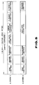
- CD-I is a standard employing mode 2, and the contents of the data D0001 to D0001 are prescribed as shown in Figure 4.
- Figure 5 shows forms 1 and 2 of the CD-I standard, in which 12 synchronizing bits and 4 header bytes are the same as those of the CD-R0M mode 2 shown in Figures 2 and 3.
- the next 8 sub-header bytes are prescribed as shown in Figure 4 wherein data D0001 and D0005 are file numbers, data D0002 and D0006 are channel numbers, data D0003 and D0007 are sub-mode data and data D0004 and D0008 are data type data.
- the data D0001 to D0004 and data D0005 to D0008 are the same data written in duplicate.
- the next 2328 bytes consist of 2048 user data bytes, four error-detecting bytes, 172 P parity bytes and 104 Q parity bytes, for form 1 of Figure 5A.
- This form 1 is used for recording letter data, binary data and high compression video data.
- the 2328 bytes for form 2 of Figure 5B consist of 2324 user data bytes, downstream of the sub-header data, and the remaining 4 reserve data bytes.
- This form 2 is used for recording compressed audio data or video data.
- 18 128-byte sound groups (2304 bytes ) are arrayed in the 2324 user data bytes, with the remaining 20 bytes representing a vacant space.
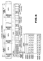
- a coding operation such as parity addition or interleaving or EFM encoding is carried out by the encoder 15, so that recording is performed with a recording format shown in Figure 6.
- each block or sector consists of 98 frames of 1st to 98th frames, with each frame being 588 times a channel clock period T (588T).
- T channel clock period
- each frame there are a frame synchronizing pattern part of 24T (plus 3T for linking), a sub-code part of 14T (plus 3T for linking), and a data part of 544T (for audio data and parity data).
- the 544T data part consists of 12 bytes or symbols of audio data, 4 bytes of parity data, 12 bytes of audio data and 4 bytes of parity data which have been processed by EFM. Audio data in each frame are formed by 24 bytes or 12 words because each word of the audio sample data consists of 16 bites.
- the sub-code part is the 8-bit sub-code data which has undergone EFM and is arrayed in a block with 98 frames as a unit, each bit constituting one of 8 sub-code channels P to W.
- the sub-code parts of the first and second frames are block synch patterns S0 and S1 which violate the EFM rule, each of the sub-code channel P to W being constituted by 96 bits for the third to 98th frames.
- the above-mentioned audio data, recorded after interleaving, are deinterleaved during reproduction into audio data of a data array conforming to the regular time senuence.
- the CD-I data such as are shown in Figures 3 and 5, may be recorded in place of the audio data.
- digital data obtained at the A/D converter 12 in the disc recording/reproducing apparatus shown in Figure 1 are data similar to those of the CD-DA format, that is the audio PCM data with the sampling frequency of 44.1 kHz, the number of quantization bits equal to 16 and a data transfer rate of 75 sectors/second.
- the digital data are transmitted to the ADPCM encoder 13 so as to be bit-compressed to the above-mentioned stereo mode, the digital data are converted into data with a sampling frequency of 37.8 kHz and the number of quantization bits is compressed to 4 bits.
- the output data are the ADPCM audio data having the data transfer rate reduced to 1/4, or to 18.75 sectors/second.
- the B level stereo mode ADPCM audio data, continuously outputted at a transfer rate of 18.75 sectors/second from the ADPCM encoder 13, are supplied to the memory 14.
- the system controller 7 controls the memory 14 in such a manner that a write pointer W of the memory 14 is continuously incremented at a transfer rate of 18.75 sectors/second continuously to write the ADPCM audio data in the memory 14 at a transfer rate of 18.75 sectors/second and, when the data amount of the ADPCM audio data stored in the memory 14 exceeds a predetermined amount, a read pointer R of the memory 14 is incremented in a burst fashion at the transfer rate of 75 sectors/second to read out a predetermined amount K of the ADPCM data in a burst fashion from the memory 14 as record data at the above-mentioned transfer rate of 75 sectors/second.
- the ADPCM audio data continuously outputted at the transfer rate of for example 18.75 sectors per second from the ADPCM encoder 13 are written in the memory 14 at the above-mentioned transfer rate of 18.75 sectors/second.
- the data amount of the ADPCM data stored in the memory 14 exceeds a data amount corresponding to one cluster, one-cluster data of the ADPCM audio data is read out from the memory 14 at the transfer rate of 75 sectors/second as record data, so that input data can be continuously written in the memory 14 while a data write region K′ in excess of a predetermined amount is perpetually assured within the memory 14.
- the record data read out in a burst fashion from the memory 14 can be recorded consecutively on the recording track on the disc 2. Since a data write region in excess of a predetermined amount is maintained in the memory 14, data can be continuously written in the data writing region in excess of the predetermined amount even if the system controller 7 detects that a track jump etc has occurred due to disturbances or the like to interrupt a recording operation on the disc 2, and the reset operation may be carried out in the interim. Thus, input data can be continuously recorded without drop-out on the recording track of the disc 2.
- header time data corresponding to the physical address of the sectors are annexed to the ADPCM audio data on the sector-by-sector basis, and recorded on the sector-by-sector basis on the disc 2.
- Table of contents indicating the record region and the recording mode are recorded in a table-of-contents region.
- the system controller 7 controls the memory 22 in such a manner that, as shown in Figure 9, the write pointer W of the memory 22 is incremented at a transfer rate of 75 sectors/second to write the reproduced data in the memory 22 at the transfer rate of 75 sectors/second, the read pointer R of the memory 22 is continuously incremented at a transfer rate of 18.75 sectors/second continuously to read out the playback data from memory 22 at the transfer rate of 18.75 sectors/second, and the write pointer W of the memory 22 is intermittently incremented at the transfer rate of 75 sectors/second, so that, when the write pointer W catches up with the read pointer R, writing is discontinued. When the data amount of the playback stored in the memory 22 is lower than the predetermined amount L, writing is started again.
- the system controller 7 controls the memory 22 in such a manner that the B-level stereo mode ADPCM audio data reproduced from the recording track of the disc 2 is written in a burst fashion in the memory 22 at a transfer rate of 75 sectors/second, and read out continuously from the memory 22 as playback data at the transfer rate of 18.75 sectors/second, so that the playback data mayr be continuously read out from the memory 22 while the data read-out region in excess of the predetermined amount L is perpetually maintained within memory 22.
- the playback data intermittently written in the memory 22 may be continuously reproduced from the recording track on the disc 2 by controlling the reproducing position on the recording track of the disc 2 by the system controller 7.
- the data read-out region in excess of the predetermined amount L is perpetually maintained in the memory 22, as described previously, so that, even when the system controller 7 should detect the occurrence of a track jump etc due to, for example, disturbances, and the operation of reproducing the disc 2 is discontinued, the playback data may be read out from the data read-out region having a space in excess of the predetermined data amount to continue the outputting of the analogue audio signals, while the resetting operation may be executed in the interim.
- the present invention is not limited to the above described embodiment.
- the above disc recording/reproducing apparatus has been explained in connection with recording and/or reproduction of the B level stereo mode ADPCM audio data, recording and/or reproduction may be performed similarly of the ADPCM audio data of other modes of other CD-I systems.
- the method of data compression is also not limited to ADPCM.
- the number of sectors constituting a cluster is not limited to 32, but a cluster may be composed of any other number of sectors, such as 64 sectors.
Abstract
Description
- This invention relates to disc recording apparatus and to disc reproducing apparatus particularly, but not exclusively, for optically recorded digital data.
- An optical disc may have a recording capacity larger by two or three orders than that of a magnetic disc, while enabling accessing at a higher speed than that for a tape recording medium. An optical disc also has the advantage of contactless data recording and reproduction, so has good durability. A well known form of optical disc is the so-called compact disc (CD).
- To provide a portable and, above all, a pocketable headphone stereo or similar recording/reproducing apparatus using an optical disc, a CD with a diameter of 12 cm and a CD with a diameter of 8 cm (so-called CD single) have been proposed. However, with a disc diameter of 12 cm, the recording/reproducing apparatus is too bulky to be readily portable. Therefore, a
disc 8 cm or less in diameter would be preferred. However, in attempting to construct a portable or pocket size recording and/or reproducing apparatus for anoptical disc 8 cm or less in diameter, the following problems arise. - In the case of a standard CD format optical disc, on which are recorded stereophonic digital PCM audio signals sampled with a sampling frequency of 44.1 kHz and quantized with 16 bits, and where these signals are exclusively reproduced by the user (CD-DA format), the playback time (recording time) of a
disc 8 cm in diameter is 20 to 22 minutes at most, meaning that a symphony, for example, cannot be recorded on one disc side. A playback time of 74 minutes or longer, which is approximately equal to that of a 12 cm CD is preferred. In addition, with this CD-DA format, recording by the user is not feasible. In addition, a contactless type optical pick-up device is vulnerable to mechanical vibrations and subject to detracking or defocusing. Thus, when the apparatus is to be portable, some positive measures need to be taken to prevent adverse effects of detracking or defocusing on the reproducing operation. - On the other hand, with a CD-MO format (a format employing a recordable magneto-optical disc) as an extension format of the abovementioned standard CD format (CD-DA format), the recording/reproducing time of an 8 cm disc is only 20 to 22 minutes, as in the CD-DA format. The optical pick-up device is similarly subject to detracking or defocusing due to mechanical vibration, such that again positive measures need to be taken to prevent any adverse effects thereof on the recording/reproducing operation.
- With the CD-I (CD-interactive) format, the levels A to C as shown in the following Table 1 are prescribed as modes for recording/reproducing bit-compressed digital audio signals.

- When reproducing a disc recorded with, for example, the level B mode, signals obtained by 4-fold bit compression of standard CD-DA format digital signals are reproduced. Thus, if all of the recorded data are stereophonic audio compressed data, playback time increases 4-fold, or reproduction of 4-channel data, becomes feasible, so that reproduction for 70 minutes or longer becomes possible with an
optical disc 8 cm in diameter or less. - Meanwhile, with the CD-I format, the disc is rotationally driven at the same linear velocity as that for the standard CD-DA format, so that continuous audio compressed data are reproduced at a rate of one unit to n recorded units on the disc, where n is a figure corresponding to the playback time or the bit compression rate of data, and is equal to 4 with the level B stereo mode. This unit is termed a block or sector, which is made up of 98 frames and has a period of 1/75 second. Therefore, with this level B stereo mode, a data string in which one of 4 sectors is an audio sector, such as:


channel 1 data corresponding to the audio sector S1 are reproduced from the innermost to the outermost areas of the disc.Channel 2 data corresponding to the audio sector S2 are reproduced from the innermost to the outermost areas of the disc. Channel 3 data corresponding to the next audio sector S3 are reproduced from the innermost to the outermost areas of the disc. Finally,channel 4 data corresponding to the audio sector S4 are reproduced from the innermost to the outermost areas of the disc to enable data reproduction for a continuous 4-fold time duration. - However, for the above-mentioned continuous reproduction, several track jump operations spanning the inner and outer disc peripheries are necessitated. Since a track jump cannot be achieved instantaneously, playback data are interrupted for a short time period, meaning that the playback sound is momentarily interrupted. On the other hand, when continuous audio signals are to be recorded, it is not possible to record only the
sector 2 signals, as an example, because the data need to undergo interleaving at the time of recording. That is,sector 2 data need to be interleaved with adjoining and even near-by sectors, such as sectors S1 and S3, such that it becomes necessary to rewrite signals of previously recorded sectors. Thus it is extremely difficult to record continuous compressed audio data. - Moreover, it is desirable to permit switching selection between the above-mentioned compression modes, because then the usage of the recording/reproducing apparatus can be significantly increased. However, if it is necessary to change the rotational velocity of the disc, the recording pattern, or the signal processing operation, for each of the selected compression modes, then the circuitry becomes complex and it is difficult to make an inexpensive apparatus. It is therefore preferred that changes brought about in control operations, recording patterns, or signal processing operations as a result of the different compression modes, be as small as possible.
- According to the present invention there is provided a disc recording apparatus for recording time compressed digital data on a disc-shaped recording medium, the apparatus comprising:
storage means for temporarily storing said digital data; and
means for arranging said digital data read out from said storage means into a plurality of clusters at an interval of a predetermined number of sectors, annexing cluster-linking sectors at linking portions of each of said clusters, each of said cluster-linking sectors being longer than an interleaving length for said digital data, subsequently processing the digital data within each of said clusters by interleaving, and recording interleaved data on said medium. - According to the present invention there is also provided a disc reproducing apparatus for reproducing record data continuously recorded on a disc-shaped recording medium, the apparatus comprising: reproducing means for reproducing record data which record data are time compressed digital data previously arranged into a plurality of clusters at an interval of a predetermined number of sectors, to which have been added cluster-linking sectors so that a cluster-linking portion is of a length longer than an interleaving length for said digital data, and which have been recorded on said medium after interleaving said digital data in said cluster;
storage means for deinterleaving playback data from the apparatus and storing digital data from which said cluster linking sectors have been removed;
time expanding means supplied with said digital data intermittently read out from said storage means and outputting said digital data as time-expanded output signals; and
control means for effecting writing control of said storage means so that, when an amount of said digital data stored in said storage means becomes lower than a predetermined amount of data, said record data are started to be reproduced to write the reproduced data in said storage means so that said predetermined amount of digital data is continuously stored in said storage means, said control means also controlling a reproducing position on said medium so that reproduced data intermittently written in said memory means is continuously reproduced from the recording track on said medium. - According to the present invention there is also provided a disc reproducing apparatus comprising reproducing means for reproducing a disc-shaped recording medium on which are recorded compressed digital data arranged into a plurality of clusters at an interval of a predetermined number of sectors, provided with cluster-linking sectors each longer than an interleaving length at linking portions of each of said clusters, and subsequently interleaved, storage means for transiently storing playback data from said reproducing means, and control means causing said playback data to be written when the data volume of said playback data stored in said storage means is less than a predetermined volume, so that a read-out space in excess of a predetermined data volume is maintained in said storage means.
- The storage means minimizes changes in the recording/reproducing operation due to the difference in the compression modes, while absorbing fluctuations in the recording/reproducing operation caused by mechanical vibration. During recording, record data are written in said storage means at a data transfer rate conforming to the prevailing compression modes and are read out intermittently, that is, in a burst fashion, at a predetermined standard data transfer rate, so as to be recorded on the disc-shaped recording medium. During reproduction, data are reproduced intermittently, that is in a burst fashion, from the disc-shaped recording medium at the predetermined standard data transfer rate and are written on said storage means so as to be read out at a data transfer rate conforming to the prevailing compression mode.
- Recording on the disc-shaped recording medium is made on a cluster-by-cluster basis. Since a cluster-linking sector longer than an interleaving length is provided between adjoining clusters, recording may be made so as to be inclusive of the cluster-linking sectors to eliminate the effects of interleaving on neighbouring clusters.
- With the use of the clusters and cluster-linking sectors as a recording unit, recording may be performed independently on a cluster-by-cluster basis, without the necessity of taking the effects of interleaving on other clusters into account, so that processing as well as re-recording in the case of a recording failure may be facilitated.
- For reproduction, drop-out of playback data by the cluster-linking sectors may be buffered by provision of a memory means for temporary storage of playback data, so as to enable continuous playback data to be obtained from the memory means.
- The present invention is preferably applied to an apparatus for recording and reproducing bit compressed data (time compressed data).
- The invention will now be described by way of example with reference to the accompanying drawings, throughout which like parts are referred to by like references, and in which:
- Figure 1 is a block diagram of an optical disc recording/reproducing apparatus according to the present invention;
- Figure 2 shows a format of a cluster as a recording unit;
- Figure 3 shows an example of a data sector or block;
- Figure 4 shows the contents of a sub-header;
- Figure 5 shows a data arrangement in one sector of the CD-I format;
- Figure 6 shows a format for a frame and a block (sector) in the so-called CD standard;
- Figure 7 shows a data format employed in the apparatus of Figure 1;
- Figure 8 shows a memory-controlled memory in a recording system of the apparatus of Figure 1; and
- Figure 9 shows a memory-controlled memory in a reproducing system of the apparatus of Figure 1.
- In the disc recording/reproducing apparatus of Figure 1, a magneto-
optical disc 2 rotationally driven by aspindle motor 1 is employed as a recording medium. While a laser light is irradiated by anoptical head 3 on thedisc 2, a modulating magnetic field corresponding to recording data is applied by amagnetic head 4 to thedisc 2 for recording data along a recording track of thedisc 2. On the other hand, the recording track of thedisc 2 is traced with a laser light by theoptical head 3 for photomagnetically reproducing the recorded data. - The
optical head 3 comprises a laser light source, such as a laser diode, optical components, such as a collimator lens, an objective lens, a polarization beam splitter or a cylindrical lens, and a split photodetector, although these device are not shown, and is arranged to face themagnetic head 4 with thedisc 2 in-between. For recording data on thedisc 2, theoptical head 3 irradiates a laser light on a target track on thedisc 2 for recording data by thermomagnetic recording. The modulating magnetic field corresponding to the recording data is applied to the target track by themagnetic head 4, which is driven by ahead driving circuit 16 of the recording system which will be explained subsequently. Theoptical head 3 detects a laser light irradiated on and reflected by the target track for detecting the focusing error by a so-called astigmatic method, as well as detecting the tracking error by a so-called push-pull method. When reproducing data from thedisc 2, theoptical head 3 detects the difference of a polarization angle (Kerr rotation angle) of the reflected laser light from the target track to produce playback signals. - The output of the
optical head 3 is supplied to anRF circuit 5. TheRF circuit 5 extracts the focusing error signal and the tracking error signal from the output of theoptical head 3 and transmits the extracted signals to aservo control circuit 6 while converting the reproduced signals into corresponding binary signals and supplying the binary signals to adecoder 21 of the reproducing system, which will be explained subsequently. - The
servo control circuit 6 comprises a focusing servo circuit, a tracking servo circuit, a spindle motor servo control circuit and a thread servo control circuit, although these circuits are not shown. The focusing servo control circuit executes focusing control of an optical system of theoptical head 3 so that the focusing error signal will be reduced to zero. The tracking servo control circuit executes tracking control of the optical system of theoptical head 3 so that the tracking error signal will be reduced to zero. The spindle motor servo control circuit controls themotor 1 for rotationally driving thedisc 2 at a predetermined rotational velocity, such as at a constant linear velocity. The thread servo control circuit causes theoptical head 3 and themagnetic head 4 to be moved to a target track position on thedisc 2 designated by the system controller 7. Theservo control circuit 6, which performs these various control operations, transmits an information indicating operating states of components controlled by theservo control circuit 6 to a system controller 7. - To the system controller 7 are connected a key
input operating unit 8 and adisplay 9. The system controller 7 controls the recording system and the reproducing system with the operating mode designated by operating input information from thekey unit 8. The system controller 7 supervises, on the basis of a sector-by-sector address information reproduced from the recording track of thedisc 2 by the header time or sub-Q data, the recording position as well as the reproducing position on the recording track traced by theoptical head 3 and themagnetic head 4. The system controller 7 causes a bit compression mode to be displayed on thedisplay 9 on the basis of bit compression mode data in the reproduced data obtained from theRF circuit 5 by means of a reproducing system as later described, or of bit compression mode data in an adaptive differential PCM (ADPCM)encoder 13 switchingly selected by thekey unit 8. The system controller 7 also causes the playback time to be displayed on thedisplay 9 on the basis of a data compression ratio and the reproducing position data on the recording track in the bit compression mode. - For displaying the playback time, the sector-by-sector address information (absolute time information), reproduced from the recording track of the
disc 2 with the head time or sub-Q data, is multiplied by a reciprocal of the data compression ratio in the bit compression mode (4 in the case of 1/4 compression) to find an actual time information for display on thedisplay 9. It is noted that, if absolute time information has been recorded (preformatted) on a recording track of a magneto-optical disc, the preformatted absolute time information may be read during recording and multiplied by the reciprocal of the data compression ratio to cause display of the current position in the form of the actual recording time. - The apparatus also comprises an A/
D converter 12 to which an analogue audio signal AIN is supplied from aninput terminal 10 by way of a low-pass filter 11. - The A/
D converter 12 quantizes the audio signal AIN. The digital audio data obtained at the A/D converter 12 is transmitted to theADPCM encoder 13. TheADPCM encoder 13 processes the standard transfer rate digital audio data quantized from the audio signal AIN by the A/D converter 12 by a data compressing operation in conformity with the various modes in the CD-I system shown in Table 1, and has its operating mode designated by the system controller 7. For example, in the B-level mode of Table 1, the digital audio data are processed into compressed data (ADPCM) audio data) having a sampling frequency of 37.8 kHz, with the number of bits per sample equal to 4 before being supplied to amemory 14. The data transfer rate with the B-level stereo mode is reduced to 1/4 of the standard data transfer rate of 75 sectors/second, or 18.75 sectors/second. - In the embodiment of Figure 1, it is assumed that the sampling frequency of the A/
D converter 12 is fixed at the sampling frequency of the standard CD-DA format, or 44.1 kHz, and that, in theADPCM encoder 13, bit compression from 16 bits to 4 bits is performed after conversion of the sampling rate in conformity with the compression mode, for example, from 44.1 kHz to 37.8 kHz for level B. Alternatively, the sampling frequency of the A/D converter 12 itself may be switchingly controlled as a function of the compression modes. In this case, the cut-off frequency of the low-pass filter 11 is also switchingly controlled as a function of the switchingly controlled sampling frequencies of the A/D converter 12. That is, the sampling frequency of the A/D converter 12 and the cut-off frequency of the low-pass filter 11 may be simultaneously controlled in dependence upon the compression modes. - The
memory 14 is used as a buffer memory in which data writing and read-out are controlled by the system controller 7, and which transiently stores ADPCM audio data supplied from theADPCM encoder 13 for recording on thedisc 1 as the occasion may demand. That is, in the B-level stereo mode, the compressed audio data supplied from theADPCM encoder 13 has its transfer rate reduced to 1/4 of the standard data transfer rate of 75 sectors/second, or to 18.75 sectors/second, these compressed data being continuously written in thememory 14. Although it suffices to record the compressed data (ADPCM data) at a rate of every 4 sectors, as explained above, it is practically impossible to record the data at this rate in view of the interleaving operation, and hence the sectors are recorded continuously as later explained. Such recording is performed in a burst fashion (discontinuously) at a standard data transfer rate of 75 sectors/second, by taking advantage of a quiescent period of the time-compressed data, with a cluster, composed of a predetermined number of, for example, 32 plus a few sectors, as a recording unit. That is, in thememory 14, the B-level stereo mode ADPCM audio data which has been continuously written at the lower transfer rate of 18.75 (= 75/4) sectors/second conforming to the data compression ratio, is read out as record data in a burst fashion at the above-mentioned transfer rate of 75 sectors/second. The overall data transfer rate of the data read out and recorded in this way, inclusive of the non-recording period, is a lower rate of 18.75 sectors/second. However, an instantaneous data transfer rate within the time of the burst-like recording operation is equal to the above-mentioned standard rate of 75 sectors/second. Therefore, if the rotational velocity of the disc is the same as that of the standard CD-DA format, that is, a constant linear velocity, recording is made at the same recording density and with the same recording pattern as those of the CD-DA format. - The ADPCM audio data read out from
memory 14 in a burst fashion at the transfer rate of 75 sectors/second, that is, the record data, is supplied to anencoder 15. With a data string supplied from thememory 14 to theencoder 15, a data unit continuously recorded with each recording is composed of a plurality of, for example 32 sectors, and a few cluster-linking sectors arrayed before and after the cluster. The cluster-linking sector has a length longer than the interleaving length at theencoder 13, so that, even when the sector undergoes interleaving, data of other clusters remain unaffected. Details of the recording on the cluster-by-cluster basis will be discussed later referring to Figure 2. - The
encoder 15 processes the record data supplied in a burst fashion from thememory 14 with an error correcting coding operation, such as by parity addition or interleaving, or 8-to-14 modulation (EFM). The recording data, thus encoded by theencoder 15, is supplied to the magnetichead driving circuit 16. - To the
head driving circuit 16 is connected themagnetic head 4 and drives it to apply a modulating magnetic field conforming to the record data to thedisc 2. - On the other hand, the system controller 7 performs writing and read-out control for the
memory 14 and, based on the armory control, performs a disc recording position control so that the above-mentioned record data read out in a burst fashion frommemory 14 will be recorded continuously on the recording track of thedisc 2. For the recording position control, the record position on thedisc 1 of the record data read out in a burst fashion from thememory 14 is supervised by the system controller 7, and controls signals designating the record position on the recording track of thedisc 2 are supplied to theservo control circuit 6. - The reproducing system in the disc recording/reproducing apparatus will now be explained.
- The reproducing system reproduces the record data continuously recorded by the above-described recording system on the recording track of the
disc 2, and is provided with thedecoder 21, to which is supplied a playback output, which has been generated by theoptical head 3 tracing the recording track on thedisc 3 with a laser light and converted into binary format signals by theRF circuit 5. - The
decoder 21 is associated with theencoder 15 in the above-described recording system, and processes the playback output, converted into the binary format signals by theRF circuit 5, with the above-mentioned decoding for error correction and EFM decoding, and reproduces the above-mentioned B level stereo mode ADPCM audio data at a transfer rate of 75 sectors/second, which is faster than the normal transfer rate in the above-mentioned B level stereo mode. The reproduced data, produced by thedecoder 21, are supplied to amemory 22. - The
memory 22 has its data writing and read-out controlled by the system controller 7 so that the playback data supplied fromdecoder 21 at a transfer rate of 75 sectors/second are sequentially written at the transfer rate of 75 sectors/second. Also the playback data intermittently written at the transfer rate of 75 sectors/second in thememory 22 are continuously read out therefrom at the regular B-level stereo mode of 18.75 sectors/second. - The system controller 7 also performs a memory control of writing the reproduced data in the
memory 22 at the transfer rate of 75 sectors/second, continuously reading out the playback data from thememory 22 at the transfer rate of 18.75 sectors/second, and stopping writing to prevent overflow of data stored in thememory 22. - The system controller 7 performs, besides the above-mentioned writing and read-out control for the
memory 22, a reproducing position control for the recording track of thedisc 2, in such a manner that the playback data written by the above-mentioned memory control in thememory 22 are written therein continuously. The reproducing position control is performed by supervising a reproducing position on thedisc 1 of the above-mentioned playback data read out in a burst fashion from thememory 22 by the system controller 7, and by supplying a control signal designating the reproducing position on the recording track of thedisc 2 to theservo control circuit 6. - The B-level stereo mode ADPCM audio data, obtained as playback data read out continuously from the
memory 22 at a transfer rate of 18.75 sectors/second, are supplied to theADPCM decoder 23. - The
ADPCM decoder 23 is associated with theADPCM encoder 13 of the recording system. TheADPCM decoder 23 has its operating mode designated by the system controller 7. With the present apparatus, the B-level stereo mode ADPCM audio data are expanded by a factor of 4 for reproducing the CD-DA mode digital audio data. The reproduced digital audio data are transmitted by theADPCM decoder 23 to a D/A converter 24. - The D/
A converter 24 causes the digital audio data supplied from theADPCM decoder 23 to be converted into an analogue audio signal AOUT which is supplied via a low-pass filter 25 at anoutput terminal 26. - The reproducing system of this apparatus is provided with a digital outputting function so that the digital audio data at the output of the
ADPCM decoder 23 is outputted at adata output terminal 28 via a digital output encoder 27 as a digital audio signal DOUT. - The
disc 2 employed in the above-described apparatus preferably has a recording space of longer than 60 minutes and up to 74 minutes for stereo audio signals. With the data compression rate of 1/4 as in the above-mentioned B level mode, a recording capacity of approximately 130 M bytes is necessary. For a portable or pocketable size of apparatus, it is preferred to use a disc outside diameter of 8 cm or less. In addition, a track pitch of 1.6 µm and a linear velocity of 1.2 to 1.4 m/second, similar to those of a compact disc, are preferred. For satisfying these conditions, the disc outside diameter may be 64 mm, the outside diameter of a data recording region may be 61 mm, the inside diameter of the data recording region may be 32 mm, the inside diameter of the lead-in region may be 30 mm, and a centre hole diameter may be 10 mm. By having the disc accommodated in a disc caddy (cartridge) of 70 x 74 mm in size and presented to the market in this state, it becomes possible to record and reproduce the disc by a pocket-size recording/reproducing apparatus. The inside and outside diameters of the disc recording region for enabling recording and/or reproduction for 72 to 76 minutes with the above-mentioned 1/4 data compression mode may be suitably selected within the range of the outside diameter of 60 to 62 mm for the inside diameter of 32 mm and within the range of the outside diameter of 71 to 73 mm for the inside diameter of 50 mm. - The recording/reproducing operation of the above apparatus will now be explained in more detail.
- The record data, that is data read out from the
memory 14, is arranged into a cluster at an interval of a predetermined number of, for example 32, sectors or blocks, and several cluster-linking sectors are arrayed between adjoining clusters. In more detail, each cluster C consists of 32 sectors or blocks B0 to B31, and five linking sectors L1 to L5 are arranged between these clusters C for linking the adjoining clusters. For recording a cluster, such as a K'th cluster CK, the 32 sectors B0 to B31 of the cluster CK, and the linking clusters ahead of and following the cluster CK, namely the three sectors L3 to L5 towards the cluster CK-1, ( run- in blocks ) and the three blocks L1 to L3 towards the cluster CK+1, making a total of 38 sectors, are recorded as one unit. The 38-sector record data are transmitted from thememory 14 to theencoder 15 where interleaving is carried out from data rearrangement over a distance of up to 108 frames corresponding to ca. 1.1 sector. However, even after interleaving, the data within the cluster CK safely contained within a range of from the run-in blocks L3 to L5 to the run-out blocks L1 to L3 without affecting the remaining clusters cK-1 or CK+1. Meanwhile, dummy data, such as 0, are arrayed in the linking sectors L1 to L5 to avoid adverse effects which interleaving might have on the data per se. When recording the next cluster CK-1, three sectors L3 to L5 of the five linking sectors L1 to L5 between the current cluster and the next cluster CK+1 are used as the run-in blocks, so that the sector L3 is recorded superfluously. However, this causes no inconvenience. The sector L3 of the run-in block or the sector L3 of the run-out block may be omitted. - By recording on the cluster-by-cluster basis, there is no necessity to take interference with the adjoining clusters by interleaving into account, so that data processing may be simplified significantly. On the other hand, if the record data should be unable to be recorded normally due to malfunctions, such as defocusing, detracking, etc, re-recording may be made on the cluster-by-cluster basis and, if the record data cannot be reproduced effectively, rereading may be effected on a cluster-by-cluster basis.
- Meanwhile, each sector or block consists of 12 synchronizing bits, 4 header bytes and 2336 bytes of data per se D0001 to D2336, arrayed in this order on the time axis, making a total of 2352 bytes. This sector or block array is represented as a two-dimensional array, as shown in Figure 3, wherein the 12 synchronization bits consists of a
first byte 00H, 10 bytes FFH and a last byte 00H in the hexadecimal system (H is a hexadecimal number). The next 4-byte header consists of address parts for minute, second and block, each one byte, and a mode data byte. These mode data mainly indicate a CD-ROM mode, while a sector structure shown in Figures 2 or 3 corresponds tomode 2 of the CD-ROM format. CD-I is a standard employingmode 2, and the contents of the data D0001 to D0001 are prescribed as shown in Figure 4. - Figure 5 shows
forms R0M mode 2 shown in Figures 2 and 3. The next 8 sub-header bytes are prescribed as shown in Figure 4 wherein data D0001 and D0005 are file numbers, data D0002 and D0006 are channel numbers, data D0003 and D0007 are sub-mode data and data D0004 and D0008 are data type data. The data D0001 to D0004 and data D0005 to D0008 are the same data written in duplicate. The next 2328 bytes consist of 2048 user data bytes, four error-detecting bytes, 172 P parity bytes and 104 Q parity bytes, forform 1 of Figure 5A. Thisform 1 is used for recording letter data, binary data and high compression video data. The 2328 bytes forform 2 of Figure 5B consist of 2324 user data bytes, downstream of the sub-header data, and the remaining 4 reserve data bytes. Thisform 2 is used for recording compressed audio data or video data. In the case of the compressed audio data, 18 128-byte sound groups (2304 bytes ) are arrayed in the 2324 user data bytes, with the remaining 20 bytes representing a vacant space. - When recording the above-described sector-based data on a disc, a coding operation such as parity addition or interleaving or EFM encoding is carried out by the
encoder 15, so that recording is performed with a recording format shown in Figure 6. - Referring to Figure 6, each block or sector consists of 98 frames of 1st to 98th frames, with each frame being 588 times a channel clock period T (588T). Within each frame, there are a frame synchronizing pattern part of 24T (plus 3T for linking), a sub-code part of 14T (plus 3T for linking), and a data part of 544T (for audio data and parity data). The 544T data part consists of 12 bytes or symbols of audio data, 4 bytes of parity data, 12 bytes of audio data and 4 bytes of parity data which have been processed by EFM. Audio data in each frame are formed by 24 bytes or 12 words because each word of the audio sample data consists of 16 bites. The sub-code part is the 8-bit sub-code data which has undergone EFM and is arrayed in a block with 98 frames as a unit, each bit constituting one of 8 sub-code channels P to W. The sub-code parts of the first and second frames are block synch patterns S₀ and S₁ which violate the EFM rule, each of the sub-code channel P to W being constituted by 96 bits for the third to 98th frames.
- The above-mentioned audio data, recorded after interleaving, are deinterleaved during reproduction into audio data of a data array conforming to the regular time senuence. The CD-I data, such as are shown in Figures 3 and 5, may be recorded in place of the audio data.
- Meanwhile, digital data obtained at the A/
D converter 12 in the disc recording/reproducing apparatus shown in Figure 1, are data similar to those of the CD-DA format, that is the audio PCM data with the sampling frequency of 44.1 kHz, the number of quantization bits equal to 16 and a data transfer rate of 75 sectors/second. When the data are transmitted to theADPCM encoder 13 so as to be bit-compressed to the above-mentioned stereo mode, the digital data are converted into data with a sampling frequency of 37.8 kHz and the number of quantization bits is compressed to 4 bits. Thus the output data are the ADPCM audio data having the data transfer rate reduced to 1/4, or to 18.75 sectors/second. The B level stereo mode ADPCM audio data, continuously outputted at a transfer rate of 18.75 sectors/second from theADPCM encoder 13, are supplied to thememory 14. - Referring to Figure 8, the system controller 7 controls the
memory 14 in such a manner that a write pointer W of thememory 14 is continuously incremented at a transfer rate of 18.75 sectors/second continuously to write the ADPCM audio data in thememory 14 at a transfer rate of 18.75 sectors/second and, when the data amount of the ADPCM audio data stored in thememory 14 exceeds a predetermined amount, a read pointer R of thememory 14 is incremented in a burst fashion at the transfer rate of 75 sectors/second to read out a predetermined amount K of the ADPCM data in a burst fashion from thememory 14 as record data at the above-mentioned transfer rate of 75 sectors/second. - That is, in the recording system of the apparatus of Figure 1, the ADPCM audio data continuously outputted at the transfer rate of for example 18.75 sectors per second from the
ADPCM encoder 13 are written in thememory 14 at the above-mentioned transfer rate of 18.75 sectors/second. When the data amount of the ADPCM data stored in thememory 14 exceeds a data amount corresponding to one cluster, one-cluster data of the ADPCM audio data is read out from thememory 14 at the transfer rate of 75 sectors/second as record data, so that input data can be continuously written in thememory 14 while a data write region K′ in excess of a predetermined amount is perpetually assured within thememory 14. By recording the recording position on the recording track of thedisc 2 under control by the system controller 7, the record data read out in a burst fashion from thememory 14 can be recorded consecutively on the recording track on thedisc 2. Since a data write region in excess of a predetermined amount is maintained in thememory 14, data can be continuously written in the data writing region in excess of the predetermined amount even if the system controller 7 detects that a track jump etc has occurred due to disturbances or the like to interrupt a recording operation on thedisc 2, and the reset operation may be carried out in the interim. Thus, input data can be continuously recorded without drop-out on the recording track of thedisc 2. - Meanwhile, header time data corresponding to the physical address of the sectors are annexed to the ADPCM audio data on the sector-by-sector basis, and recorded on the sector-by-sector basis on the
disc 2. Table of contents indicating the record region and the recording mode are recorded in a table-of-contents region. - In the reproducing system of the apparatus of Figure 1, the system controller 7 controls the
memory 22 in such a manner that, as shown in Figure 9, the write pointer W of thememory 22 is incremented at a transfer rate of 75 sectors/second to write the reproduced data in thememory 22 at the transfer rate of 75 sectors/second, the read pointer R of thememory 22 is continuously incremented at a transfer rate of 18.75 sectors/second continuously to read out the playback data frommemory 22 at the transfer rate of 18.75 sectors/second, and the write pointer W of thememory 22 is intermittently incremented at the transfer rate of 75 sectors/second, so that, when the write pointer W catches up with the read pointer R, writing is discontinued. When the data amount of the playback stored in thememory 22 is lower than the predetermined amount L, writing is started again. - Thus, with the above described reproducing system of the disc recording/reproducing apparatus, the system controller 7 controls the
memory 22 in such a manner that the B-level stereo mode ADPCM audio data reproduced from the recording track of thedisc 2 is written in a burst fashion in thememory 22 at a transfer rate of 75 sectors/second, and read out continuously from thememory 22 as playback data at the transfer rate of 18.75 sectors/second, so that the playback data mayr be continuously read out from thememory 22 while the data read-out region in excess of the predetermined amount L is perpetually maintained withinmemory 22. Also the playback data intermittently written in thememory 22 may be continuously reproduced from the recording track on thedisc 2 by controlling the reproducing position on the recording track of thedisc 2 by the system controller 7. In addition, the data read-out region in excess of the predetermined amount L is perpetually maintained in thememory 22, as described previously, so that, even when the system controller 7 should detect the occurrence of a track jump etc due to, for example, disturbances, and the operation of reproducing thedisc 2 is discontinued, the playback data may be read out from the data read-out region having a space in excess of the predetermined data amount to continue the outputting of the analogue audio signals, while the resetting operation may be executed in the interim. - It is to be noted that the present invention is not limited to the above described embodiment. For example, although the above disc recording/reproducing apparatus has been explained in connection with recording and/or reproduction of the B level stereo mode ADPCM audio data, recording and/or reproduction may be performed similarly of the ADPCM audio data of other modes of other CD-I systems. The method of data compression is also not limited to ADPCM. The number of sectors constituting a cluster is not limited to 32, but a cluster may be composed of any other number of sectors, such as 64 sectors.
Claims (10)
- A disc recording apparatus for recording time compressed digital data on a disc-shaped recording medium (2), the apparatus comprising:
storage means (14) for temporarily storing said digital data; and
means (15) for arranging said digital data read out from said storage means (14) into a plurality of clusters (C) at an interval of a predetermined number of sectors, annexing cluster-linking sectors at linking portions of each of said clusters (C), each of said cluster-linking sectors being longer than an interleaving length for said digital data, subsequently processing the digital data within each of said clusters (C) by interleaving, and recording interleaved data on said medium (2). - Apparatus according to claim 1 further comprising control means (7) for controlling read-out of said storage means (14) so that, when the amount of said digital data stored in said storage means (14) exceeds a first predetermined amount of data, said first amount of digital data is continuously read from said storage means (14), so as continuously to maintain a writing space in excess of a second predetermined amount of data in said storage means (14);
said control means (7) also controlling a recording means (16) so that said first predetermined amount of data of record data read out intermittently from said storage means (14) is continuously recorded on a recording track on said medium (2). - Apparatus according to claim 2 wherein said control means (7) performs a control operation so that, when said recording means (16) becomes unable to record data, read-out of the record data from said storage means (14) is discontinued and said recording means (16) is reset to its recording state, said control means (7) causing the unrecordable record data to be read out again from said storage means (14) for recording continuously with the record data preceding said unrecordable data.
- Apparatus according to claim 3 wherein said second predetermined amount of data exceeds an amount of data inputted to said memory means (14) during the reset time from the non-recording state to a recording state.
- Apparatus according to claim 3 wherein said second predetermined amount of data corresponds to an amount of data for one cluster (C).
- Apparatus according to claim 1 wherein said cluster linking sector is formed by dummy data not affecting digital data in said cluster (C).
- Apparatus according to any one of the preceding claims wherein one sector corresponds to one block or 98 8-to-14 modulated frames of a compact disc.
- A disc reproducing apparatus for reproducing record data continuously recorded on a disc-shaped recording medium (2), the apparatus comprising:
reproducing means (3) for reproducing record data which record data are time compressed digital data previously arranged into a plurality of clusters (C) at an interval of a predetermined number of sectors, to which have been added cluster-linking sectors so that a cluster-linking portion is of a length longer than an interleaving length for said digital data, and which have been recorded on said medium (2) after interleaving said digital data in said cluster (C);
storage means (22) for deinterleaving playback data from the apparatus and storing digital data from which said cluster linking sectors have been removed;
time expanding means (23) supplied with said digital data intermittently read out from said storage means (22) and outputting said digital data as time-expanded output signals; and
control means (7) for effecting writing control of said storage means (22) so that, when an amount of said digital data stored in said storage means (22) becomes lower than a predetermined amount of data, said record data are started to be reproduced to write the reproduced data in said storage means (22) so that said predetermined amount of digital data is continuously stored in said storage means (22), said control means (7) also controlling a reproducing position on said medium (2) so that reproduced data intermittently written in said memory means (22) is continuously reproduced from the recording track on said medium (2). - Apparatus according to claim 8 wherein said control means (7) detects that said reproducing means (3) is in a non-reproducing state to terminate writing of digital data in said memory means (22), to reset said reproducing means (3) to a reproducing state, said control means (7) then operating to reproduce unreproduced playback data from said medium (2) again to write said reproduced unreproduced playback data is said memory means (22) continuous with prior playback data.
- Apparatus according to claim 9 wherein said predetermined amount of data stored in said storage means (22) is in excess of an amount of digital data read out from said storage means (22) during resetting from said non-recording state to said recording state.
Applications Claiming Priority (2)
| Application Number | Priority Date | Filing Date | Title |
|---|---|---|---|
| JP02222821A JP3141241B2 (en) | 1990-08-24 | 1990-08-24 | Disk recording device and disk reproducing device |
| JP222821/90 | 1990-08-24 |
Publications (2)
| Publication Number | Publication Date |
|---|---|
| EP0472343A1 true EP0472343A1 (en) | 1992-02-26 |
| EP0472343B1 EP0472343B1 (en) | 1996-03-20 |
Family
ID=16788440
Family Applications (1)
| Application Number | Title | Priority Date | Filing Date |
|---|---|---|---|
| EP91307446A Expired - Lifetime EP0472343B1 (en) | 1990-08-24 | 1991-08-13 | Disc recording and reproducing apparatus |
Country Status (12)
| Country | Link |
|---|---|
| US (2) | US5243588A (en) |
| EP (1) | EP0472343B1 (en) |
| JP (1) | JP3141241B2 (en) |
| KR (1) | KR100242901B1 (en) |
| CN (1) | CN1026532C (en) |
| AT (1) | ATE135842T1 (en) |
| AU (1) | AU646879B2 (en) |
| CA (1) | CA2049280C (en) |
| DE (1) | DE69118050T2 (en) |
| MY (1) | MY106916A (en) |
| RU (1) | RU2054203C1 (en) |
| SG (1) | SG49885A1 (en) |
Cited By (13)
| Publication number | Priority date | Publication date | Assignee | Title |
|---|---|---|---|---|
| EP0571221A2 (en) * | 1992-05-22 | 1993-11-24 | Sony Corporation | Disc recording apparatus |
| EP0570922A2 (en) * | 1992-05-20 | 1993-11-24 | Sony Corporation | Reproducing apparatus |
| EP0596417A2 (en) * | 1992-10-31 | 1994-05-11 | Sony Corporation | Memory controller, reproducing apparatus, mounting the same and method for controlling the same |
| EP0613136A2 (en) * | 1993-02-24 | 1994-08-31 | Sony Corporation | Data recording and reproducing method |
| WO1994019801A1 (en) * | 1993-02-18 | 1994-09-01 | Sony Corporation | Apparatus, method, and system for compressing a digital input signal in more than one compression mode |
| EP0615349A2 (en) * | 1993-03-09 | 1994-09-14 | Sony Corporation | Methods and apparatus for recording, reproducing, transmitting and/or receiving compressed data and recording medium therefor |
| EP0621596A2 (en) * | 1993-04-23 | 1994-10-26 | Sony Corporation | Memory control device and recording and/or reproducing apparatus |
| EP0635835A2 (en) * | 1993-07-23 | 1995-01-25 | Sony Corporation | Recording medium, recording and/or reproducing apparatus and recording and/or reproducing method |
| EP0673027A2 (en) * | 1994-03-16 | 1995-09-20 | Kabushiki Kaisha Toshiba | Recording medium and method for recording a signal thereon |
| EP0675493A2 (en) * | 1994-03-28 | 1995-10-04 | Kabushiki Kaisha Toshiba | Method of recording/reproducing optical disk by sector link data including address information of unit data or a program related to sectors, disk including the sector link data, and apparatus for and method of reproducing the disk |
| US5829050A (en) * | 1993-04-23 | 1998-10-27 | Sony Corporation | Memory control device and memory data search circuit |
| US5897652A (en) * | 1993-04-23 | 1999-04-27 | Sony Corporation | Memory control device and address generating circuit |
| EP1506545A1 (en) * | 2002-05-20 | 2005-02-16 | Samsung Electronics Co., Ltd. | Optical disc and method for recording data on the same |
Families Citing this family (111)
| Publication number | Priority date | Publication date | Assignee | Title |
|---|---|---|---|---|
| US5115240A (en) * | 1989-09-26 | 1992-05-19 | Sony Corporation | Method and apparatus for encoding voice signals divided into a plurality of frequency bands |
| JP3006158B2 (en) * | 1991-05-09 | 2000-02-07 | ソニー株式会社 | Disk recording device and disk reproducing device |
| JP3395192B2 (en) * | 1991-05-25 | 2003-04-07 | ソニー株式会社 | Digital audio signal reproduction device, reproduction pause circuit of disk player, and reproduction control circuit of disk reproduction device |
| JP3163686B2 (en) * | 1991-10-08 | 2001-05-08 | ソニー株式会社 | Playback device |
| DE69230126T2 (en) * | 1991-11-27 | 2000-04-06 | Canon Kk | Playback device |
| JP2843703B2 (en) * | 1992-01-24 | 1999-01-06 | 株式会社ケンウッド | Digital recording and playback device |
| DE69322529T2 (en) * | 1992-02-05 | 1999-04-29 | Sony Corp | Disc player and disc recorder |
| DE69318598T2 (en) * | 1992-02-29 | 1998-09-10 | Sony Corp | Optical disk recording apparatus |
| US5680379A (en) * | 1992-04-20 | 1997-10-21 | Mitsubishi Denki Kabushiki Kaisha | Information reproduction apparatus having means to control maximum delay of information being read from memory |
| JP3355649B2 (en) * | 1992-05-20 | 2002-12-09 | ソニー株式会社 | Recording or playback device |
| JP3435712B2 (en) * | 1992-05-22 | 2003-08-11 | ソニー株式会社 | Playing method of disc reproducing apparatus, disc reproducing apparatus |
| JP2788380B2 (en) * | 1992-06-11 | 1998-08-20 | シャープ株式会社 | Digital information reproducing device |
| JP3153933B2 (en) * | 1992-06-16 | 2001-04-09 | ソニー株式会社 | Data encoding device and method and data decoding device and method |
| JP3230319B2 (en) * | 1992-07-09 | 2001-11-19 | ソニー株式会社 | Sound reproduction device |
| US5426540A (en) * | 1992-08-07 | 1995-06-20 | Teac Corporation | Digital audio reproducing apparatus |
| JP3318841B2 (en) * | 1992-08-20 | 2002-08-26 | ソニー株式会社 | Reproduction device and reproduction method |
| DE69328917T2 (en) * | 1992-09-03 | 2000-12-28 | Sony Corp | Data recording device and method |
| JPH06139697A (en) * | 1992-10-29 | 1994-05-20 | Kenwood Corp | Optical disk recording and reproducing device |
| JPH06153156A (en) * | 1992-11-02 | 1994-05-31 | Fujitsu Ltd | Movie reproduction system |
| JP3431030B2 (en) * | 1992-11-12 | 2003-07-28 | ソニー株式会社 | Reproduction device and reproduction method |
| JP3199082B2 (en) * | 1992-11-18 | 2001-08-13 | ソニー株式会社 | Audio data break position adjustment method and apparatus |
| JPH06180948A (en) * | 1992-12-11 | 1994-06-28 | Sony Corp | Method and unit for processing digital signal and recording medium |
| JPH07176174A (en) * | 1992-12-25 | 1995-07-14 | Mitsubishi Electric Corp | Disk device |
| EP0833338B1 (en) * | 1993-01-06 | 2006-04-05 | Sony Corporation | Recording method of recording medium |
| TW223171B (en) * | 1993-01-06 | 1994-05-01 | Sony Co Ltd | Playback method and device |
| KR940018849A (en) * | 1993-01-28 | 1994-08-19 | 프레데릭 얀 스미트 | Arrangement for recording a video signal and a corresponding audio signal in slant tracks on a longitudinal magnetic record carrier, and record carrier obtained by means of the arrangement) |
| JP3186292B2 (en) * | 1993-02-02 | 2001-07-11 | ソニー株式会社 | High efficiency coding method and apparatus |
| DE4303453A1 (en) * | 1993-02-08 | 1994-08-11 | Thomson Brandt Gmbh | Method for recording and reproducing a time-compressed signal |
| JP3141308B2 (en) * | 1993-02-24 | 2001-03-05 | ソニー株式会社 | Digital recording and playback device |
| WO1994019802A1 (en) * | 1993-02-25 | 1994-09-01 | Sony Corporation | Disk recording apparatus |
| JP3186307B2 (en) * | 1993-03-09 | 2001-07-11 | ソニー株式会社 | Compressed data recording apparatus and method |
| JP3531177B2 (en) * | 1993-03-11 | 2004-05-24 | ソニー株式会社 | Compressed data recording apparatus and method, compressed data reproducing method |
| EP0645765B1 (en) * | 1993-03-26 | 1999-09-08 | Sony Corporation | Disklike recording medium, apparatus for recording data on disk, and apparatus for reproducing data from disk |
| US5563859A (en) * | 1993-04-07 | 1996-10-08 | Matsushita Electric Industrial Co., Ltd. | Method for simultaneous recording and playback from both sides of a recording medium |
| JP3173218B2 (en) * | 1993-05-10 | 2001-06-04 | ソニー株式会社 | Compressed data recording method and apparatus, compressed data reproducing method, and recording medium |
| US5966495A (en) * | 1993-05-12 | 1999-10-12 | Canon Kabushiki Kaisha | Recording and reproducing apparatus |
| US5581654A (en) * | 1993-05-25 | 1996-12-03 | Sony Corporation | Method and apparatus for information encoding and decoding |
| ATE211326T1 (en) * | 1993-05-31 | 2002-01-15 | Sony Corp | METHOD AND DEVICE FOR ENCODING OR DECODING SIGNALS AND RECORDING MEDIUM |
| RU2131169C1 (en) * | 1993-06-30 | 1999-05-27 | Сони Корпорейшн | Device for signal encoding, device for signal decoding, information carrier and method for encoding and decoding |
| TW327223B (en) * | 1993-09-28 | 1998-02-21 | Sony Co Ltd | Methods and apparatus for encoding an input signal broken into frequency components, methods and apparatus for decoding such encoded signal |
| WO1995010886A1 (en) | 1993-10-08 | 1995-04-20 | Sony Corporation | Digital signal processor, digital signal processing method and data recording medium |
| JP3517907B2 (en) * | 1993-10-08 | 2004-04-12 | ソニー株式会社 | Disk recording device |
| US5850500A (en) * | 1995-06-28 | 1998-12-15 | Kabushiki Kaisha Toshiba | Recording medium comprising a plurality of different languages which are selectable independently of each other |
| EP0836190B1 (en) * | 1993-10-29 | 1999-08-11 | Kabushiki Kaisha Toshiba | Information recording disk medium and reproduction apparatus |
| US5608713A (en) * | 1994-02-09 | 1997-03-04 | Sony Corporation | Bit allocation of digital audio signal blocks by non-linear processing |
| DE69535009T2 (en) * | 1994-03-19 | 2007-01-04 | Sony Corp. | Optical disc and method and apparatus for recording and playing back from this disc |
| JP3186412B2 (en) * | 1994-04-01 | 2001-07-11 | ソニー株式会社 | Information encoding method, information decoding method, and information transmission method |
| JP3467832B2 (en) * | 1994-04-20 | 2003-11-17 | ソニー株式会社 | Recording method and recording device |
| JP3277699B2 (en) * | 1994-06-13 | 2002-04-22 | ソニー株式会社 | Signal encoding method and apparatus, and signal decoding method and apparatus |
| JP2856072B2 (en) * | 1994-06-27 | 1999-02-10 | 株式会社日立製作所 | Information recording method, information reproducing method and information reproducing apparatus |
| JP2760287B2 (en) * | 1994-07-01 | 1998-05-28 | ヤマハ株式会社 | Disk recording and playback device |
| JP3329351B2 (en) * | 1994-07-22 | 2002-09-30 | ソニー株式会社 | Interactive broadcast system and reply system |
| JP3277705B2 (en) | 1994-07-27 | 2002-04-22 | ソニー株式会社 | Information encoding apparatus and method, and information decoding apparatus and method |
| JP3341474B2 (en) * | 1994-07-28 | 2002-11-05 | ソニー株式会社 | Information encoding method and decoding method, information encoding device and decoding device, and information recording medium |
| JP3560074B2 (en) * | 1994-07-29 | 2004-09-02 | ソニー株式会社 | Recording / reproducing device and memory control device |
| US5602815A (en) * | 1994-08-09 | 1997-02-11 | Wea Manufacturing, Inc. | Method and apparatus for combining CD-ROM data and digital audio on a single disc |
| JP3644455B2 (en) * | 1994-09-29 | 2005-04-27 | ソニー株式会社 | Program information broadcasting system, program information display method and receiving apparatus |
| US5654952A (en) * | 1994-10-28 | 1997-08-05 | Sony Corporation | Digital signal encoding method and apparatus and recording medium |
| JP3503231B2 (en) * | 1994-11-30 | 2004-03-02 | ソニー株式会社 | Recording device |
| JP3557674B2 (en) * | 1994-12-15 | 2004-08-25 | ソニー株式会社 | High efficiency coding method and apparatus |
| JP3371590B2 (en) * | 1994-12-28 | 2003-01-27 | ソニー株式会社 | High efficiency coding method and high efficiency decoding method |
| US6009202A (en) * | 1994-12-28 | 1999-12-28 | Kabushiki Kaisha Toshiba | Image information encoding/decoding system |
| US5721720A (en) * | 1994-12-28 | 1998-02-24 | Kabushiki Kaisha Toshiba | Optical recording medium recording pixel data as a compressed unit data block |
| JP3591028B2 (en) * | 1995-01-25 | 2004-11-17 | ソニー株式会社 | Playback device and playback method |
| CA2168327C (en) * | 1995-01-30 | 2000-04-11 | Shinichi Kikuchi | A recording medium on which a data containing navigation data is recorded, a method and apparatus for reproducing a data according to navigationdata, a method and apparatus for recording a data containing navigation data on a recording medium. |
| WO1996029641A1 (en) * | 1995-03-23 | 1996-09-26 | Elonex Technologies, Inc. | Compact disk read-only memory with integrated sound card |
| US6009433A (en) * | 1995-04-14 | 1999-12-28 | Kabushiki Kaisha Toshiba | Information storage and information transmission media with parental control |
| US6009234A (en) * | 1995-04-14 | 1999-12-28 | Kabushiki Kaisha Toshiba | Method of reproducing information |
| US5813010A (en) * | 1995-04-14 | 1998-09-22 | Kabushiki Kaisha Toshiba | Information storage and information transmission media with parental control |
| CA2173929C (en) * | 1995-04-14 | 2001-04-03 | Kazuhiko Taira | Method, apparatus and recording medium for reproducing information |
| JP3557721B2 (en) * | 1995-05-11 | 2004-08-25 | ソニー株式会社 | Recording device |
| DE69626478T2 (en) * | 1995-07-13 | 2003-11-20 | Koninkl Philips Electronics Nv | METHOD AND SYSTEM FOR REPEATING DATA BETWEEN LOGICALLY FOLLOWING CLUSTERS |
| US5751672A (en) * | 1995-07-26 | 1998-05-12 | Sony Corporation | Compact disc changer utilizing disc database |
| JP3951317B2 (en) * | 1995-09-28 | 2007-08-01 | ソニー株式会社 | Apparatus and method for data recording / reproduction |
| JPH09265731A (en) | 1996-01-24 | 1997-10-07 | Sony Corp | Speech reproducing device and its method, speech recording device and its method, speech recording and reproducing system, speech data transfer method, information receiving device, and reproducing device |
| US5995470A (en) * | 1996-04-11 | 1999-11-30 | Sony Corporation | Method of recording and reproducing information signals and apparatus for editing the same |
| US6049517A (en) | 1996-04-30 | 2000-04-11 | Sony Corporation | Dual format audio signal compression |
| US5830590A (en) * | 1996-06-28 | 1998-11-03 | Ampex Corporation | Magnetic storage and reproducing system with a low permeability keeper and a self-biased magnetoresistive reproduce head |
| US5861220A (en) * | 1996-08-06 | 1999-01-19 | Ampex Corporation | Method and apparatus for providing a magnetic storage and reproducing media with a keeper layer having a longitudinal anisotropy |
| JP3363712B2 (en) * | 1996-08-06 | 2003-01-08 | 株式会社リコー | Optical disk drive |
| JPH1064195A (en) * | 1996-08-15 | 1998-03-06 | Toshiba Corp | Disk reproducing device |
| JPH1064244A (en) * | 1996-08-23 | 1998-03-06 | Sony Corp | Storage medium and reproducing device |
| JP3845849B2 (en) * | 1996-10-18 | 2006-11-15 | ソニー株式会社 | Recording apparatus, recording method, and recording medium |
| US5843565A (en) * | 1996-10-31 | 1998-12-01 | Ampex Corporation | Particulate magnetic medium utilizing keeper technology and methods of manufacture |
| JP3796858B2 (en) * | 1996-11-15 | 2006-07-12 | ヤマハ株式会社 | Optical disk reading device |
| JPH10228728A (en) * | 1997-02-17 | 1998-08-25 | Sony Corp | Digital signal recording method and device therefor digital signal reproduction method and device therefor |
| JP4144054B2 (en) * | 1997-07-24 | 2008-09-03 | ソニー株式会社 | Optical disc recording method |
| US7558472B2 (en) | 2000-08-22 | 2009-07-07 | Tivo Inc. | Multimedia signal processing system |
| US8380041B2 (en) * | 1998-07-30 | 2013-02-19 | Tivo Inc. | Transportable digital video recorder system |
| US8577205B2 (en) | 1998-07-30 | 2013-11-05 | Tivo Inc. | Digital video recording system |
| US6233389B1 (en) | 1998-07-30 | 2001-05-15 | Tivo, Inc. | Multimedia time warping system |
| JP2000123549A (en) | 1998-10-13 | 2000-04-28 | Sony Corp | Reproducer and recorder |
| US20020048224A1 (en) * | 1999-01-05 | 2002-04-25 | Dygert Timothy W. | Playback device having text display and communication with remote database of titles |
| KR100544175B1 (en) * | 1999-05-08 | 2006-01-23 | 삼성전자주식회사 | Recording medium storing linking type information and method for processing defective area |
| JP2002007073A (en) * | 2000-06-22 | 2002-01-11 | Pioneer Electronic Corp | Device and method for outputting information, device and method for recording information, information output recording system and information recording medium |
| JP2004507820A (en) | 2000-08-23 | 2004-03-11 | コーニンクレッカ フィリップス エレクトロニクス エヌ ヴィ | Method, client system and server system for improving content item rendering |
| KR100713095B1 (en) * | 2000-12-26 | 2007-05-02 | 파이오니아 가부시키가이샤 | Information recording medium, and information reproducing apparatus and its method |
| US20020123926A1 (en) * | 2001-03-01 | 2002-09-05 | Bushold Thomas R. | System and method for implementing a loyalty program incorporating on-line and off-line transactions |
| KR100788650B1 (en) * | 2001-10-13 | 2007-12-26 | 삼성전자주식회사 | High density disk |
| US7233550B2 (en) | 2002-09-30 | 2007-06-19 | Lg Electronics Inc. | Write-once optical disc, and method and apparatus for recording management information on write-once optical disc |
| KR20040028469A (en) | 2002-09-30 | 2004-04-03 | 엘지전자 주식회사 | Method for managing a defect area on optical disc write once |
| JP4914610B2 (en) * | 2002-12-11 | 2012-04-11 | エルジー エレクトロニクス インコーポレイティド | Overwrite management method and management information recording method for write-once optical disc |
| TWI314315B (en) | 2003-01-27 | 2009-09-01 | Lg Electronics Inc | Optical disc of write once type, method, and apparatus for managing defect information on the optical disc |
| WO2004084218A2 (en) * | 2003-03-19 | 2004-09-30 | Koninklijke Philips Electronics N.V. | Method of storing information on an optical disc |
| JP4846566B2 (en) | 2003-05-09 | 2011-12-28 | エルジー エレクトロニクス インコーポレイティド | Optical disk that can be recorded only once, and method and apparatus for restoring management information from an optical disk that can be recorded only once |
| US7313065B2 (en) | 2003-08-05 | 2007-12-25 | Lg Electronics Inc. | Write-once optical disc, and method and apparatus for recording/reproducing management information on/from optical disc |
| US7382707B2 (en) * | 2003-12-03 | 2008-06-03 | Mediatek Inc. | Recording method and apparatus for optical disk drive |
| US8254218B2 (en) * | 2003-12-03 | 2012-08-28 | Mediatek Inc. | Recording method and apparatus for optical disk drive |
| TWI245272B (en) * | 2003-12-03 | 2005-12-11 | Mediatek Inc | Recording method and apparatus for optical disk drive |
| AU2005306361B2 (en) | 2004-11-19 | 2011-02-10 | Tivo Inc. | Method and apparatus for secure transfer of previously broadcasted content |
| JP7409043B2 (en) * | 2019-11-25 | 2024-01-09 | セイコーエプソン株式会社 | Media processing device, control method for media processing device, and program |
Citations (3)
| Publication number | Priority date | Publication date | Assignee | Title |
|---|---|---|---|---|
| EP0260722A2 (en) * | 1986-09-19 | 1988-03-23 | Kabushiki Kaisha Toshiba | Erroneous track jump restoration apparatus for optical record disc player |
| EP0288571A1 (en) * | 1986-10-16 | 1988-11-02 | Sony Corporation | Apparatus for recording and reproducing data using a disk |
| EP0326437A2 (en) * | 1988-01-29 | 1989-08-02 | Sharp Kabushiki Kaisha | Optical disk recording and reproducing device |
Family Cites Families (7)
| Publication number | Priority date | Publication date | Assignee | Title |
|---|---|---|---|---|
| MX158466A (en) * | 1984-11-01 | 1989-02-03 | Sony Corp | RECORDER AND / OR PLAYER OF SIGNALS |
| JP2519408B2 (en) * | 1985-02-12 | 1996-07-31 | キヤノン株式会社 | Recording device |
| EP0196590B1 (en) * | 1985-03-27 | 1992-05-20 | Sony Corporation | Signal recording and reproducing apparatus for an opto-magnetic disk |
| JPH01143080A (en) * | 1987-11-30 | 1989-06-05 | Sony Corp | Recording device |
| JPH02104193A (en) * | 1988-10-13 | 1990-04-17 | Pioneer Electron Corp | Image reproducing device |
| JP2845920B2 (en) * | 1989-02-09 | 1999-01-13 | パイオニア株式会社 | Recording / playback method |
| JP2881980B2 (en) * | 1990-06-29 | 1999-04-12 | ソニー株式会社 | Disk recording device and disk reproducing device |
-
1990
- 1990-08-24 JP JP02222821A patent/JP3141241B2/en not_active Expired - Lifetime
-
1991
- 1991-08-13 SG SG1996008142A patent/SG49885A1/en unknown
- 1991-08-13 DE DE69118050T patent/DE69118050T2/en not_active Expired - Lifetime
- 1991-08-13 EP EP91307446A patent/EP0472343B1/en not_active Expired - Lifetime
- 1991-08-13 AT AT91307446T patent/ATE135842T1/en not_active IP Right Cessation
- 1991-08-15 CA CA002049280A patent/CA2049280C/en not_active Expired - Lifetime
- 1991-08-16 US US07/746,787 patent/US5243588A/en not_active Expired - Lifetime
- 1991-08-19 MY MYPI91001503A patent/MY106916A/en unknown
- 1991-08-20 AU AU82650/91A patent/AU646879B2/en not_active Expired
- 1991-08-20 KR KR1019910014301A patent/KR100242901B1/en not_active IP Right Cessation
- 1991-08-23 CN CN91105980A patent/CN1026532C/en not_active Expired - Lifetime
- 1991-08-23 RU SU915001474A patent/RU2054203C1/en active
-
1993
- 1993-04-15 US US08/048,359 patent/US5363362A/en not_active Expired - Lifetime
Patent Citations (3)
| Publication number | Priority date | Publication date | Assignee | Title |
|---|---|---|---|---|
| EP0260722A2 (en) * | 1986-09-19 | 1988-03-23 | Kabushiki Kaisha Toshiba | Erroneous track jump restoration apparatus for optical record disc player |
| EP0288571A1 (en) * | 1986-10-16 | 1988-11-02 | Sony Corporation | Apparatus for recording and reproducing data using a disk |
| EP0326437A2 (en) * | 1988-01-29 | 1989-08-02 | Sharp Kabushiki Kaisha | Optical disk recording and reproducing device |
Cited By (33)
| Publication number | Priority date | Publication date | Assignee | Title |
|---|---|---|---|---|
| EP0570922A2 (en) * | 1992-05-20 | 1993-11-24 | Sony Corporation | Reproducing apparatus |
| US5477516A (en) * | 1992-05-20 | 1995-12-19 | Sony Coporation | Reproducing apparatus for accessing track segments in the forward and reverse directions |
| EP0570922A3 (en) * | 1992-05-20 | 1995-06-21 | Sony Corp | Reproducing apparatus. |
| EP0571221A3 (en) * | 1992-05-22 | 1995-10-25 | Sony Corp | Disc recording apparatus |
| EP0571221A2 (en) * | 1992-05-22 | 1993-11-24 | Sony Corporation | Disc recording apparatus |
| EP0596417A2 (en) * | 1992-10-31 | 1994-05-11 | Sony Corporation | Memory controller, reproducing apparatus, mounting the same and method for controlling the same |
| US6272084B1 (en) | 1992-10-31 | 2001-08-07 | Sony Corporation | Memory controller, reproducing apparatus mounting the same and method for controlling the same |
| EP0596417A3 (en) * | 1992-10-31 | 1995-09-27 | Sony Corp | Memory controller, reproducing apparatus, mounting the same and method for controlling the same |
| AU675295B2 (en) * | 1993-02-18 | 1997-01-30 | Sony Corporation | Apparatus, method, and system for compressing a digital input signal in more than one compression mode |
| WO1994019801A1 (en) * | 1993-02-18 | 1994-09-01 | Sony Corporation | Apparatus, method, and system for compressing a digital input signal in more than one compression mode |
| EP0613136A2 (en) * | 1993-02-24 | 1994-08-31 | Sony Corporation | Data recording and reproducing method |
| EP0613136A3 (en) * | 1993-02-24 | 1999-02-03 | Sony Corporation | Data recording and reproducing method |
| EP0615349A3 (en) * | 1993-03-09 | 1998-06-03 | Sony Corporation | Methods and apparatus for recording, reproducing, transmitting and/or receiving compressed data and recording medium therefor |
| EP0615349A2 (en) * | 1993-03-09 | 1994-09-14 | Sony Corporation | Methods and apparatus for recording, reproducing, transmitting and/or receiving compressed data and recording medium therefor |
| US5553048A (en) * | 1993-04-23 | 1996-09-03 | Sony Corporation | Memory control device and reproducing and/or recording apparatus |
| US5870583A (en) * | 1993-04-23 | 1999-02-09 | Sony Corporation | Method of editing information for managing recordable segments of a recording medium where scanned and reference addresses are compared |
| US6343054B1 (en) | 1993-04-23 | 2002-01-29 | Sony Corporation | Recording/reproducing device with memory controller which creates sector data storing area and additive data storing area |
| EP0621596A3 (en) * | 1993-04-23 | 1995-09-27 | Sony Corp | Memory control device and recording and/or reproducing apparatus. |
| US6298030B1 (en) | 1993-04-23 | 2001-10-02 | Sony Corporation | Memory control and reproducing and/or recording apparatus for storage and access of memory location |
| EP0621596A2 (en) * | 1993-04-23 | 1994-10-26 | Sony Corporation | Memory control device and recording and/or reproducing apparatus |
| US5829050A (en) * | 1993-04-23 | 1998-10-27 | Sony Corporation | Memory control device and memory data search circuit |
| US5915263A (en) * | 1993-04-23 | 1999-06-22 | Sony Corporation | Memory control device and memory data search circuit |
| US5897652A (en) * | 1993-04-23 | 1999-04-27 | Sony Corporation | Memory control device and address generating circuit |
| US6249641B1 (en) | 1993-07-23 | 2001-06-19 | Sony Corporation | Recording medium, recording and/or reproducing apparatus and recording and/or reproducing method |
| EP0635835A2 (en) * | 1993-07-23 | 1995-01-25 | Sony Corporation | Recording medium, recording and/or reproducing apparatus and recording and/or reproducing method |
| EP0635835A3 (en) * | 1993-07-23 | 1996-02-14 | Sony Corp | Recording medium, recording and/or reproducing apparatus and recording and/or reproducing method. |
| EP0673027A3 (en) * | 1994-03-16 | 1999-01-27 | Kabushiki Kaisha Toshiba | Recording medium and method for recording a signal thereon |
| EP0673027A2 (en) * | 1994-03-16 | 1995-09-20 | Kabushiki Kaisha Toshiba | Recording medium and method for recording a signal thereon |
| US5946447A (en) * | 1994-03-28 | 1999-08-31 | Kabushiki Kaisha Toshiba | Apparatus and method for recording/retrieving data on/from a disk having data stored thereon in a logical hierarchy |
| EP0675493A3 (en) * | 1994-03-28 | 1997-11-19 | Kabushiki Kaisha Toshiba | Method of recording/reproducing optical disk by sector link data including address information of unit data or a program related to sectors, disk including the sector link data, and apparatus for and method of reproducing the disk |
| EP0675493A2 (en) * | 1994-03-28 | 1995-10-04 | Kabushiki Kaisha Toshiba | Method of recording/reproducing optical disk by sector link data including address information of unit data or a program related to sectors, disk including the sector link data, and apparatus for and method of reproducing the disk |
| EP1506545A1 (en) * | 2002-05-20 | 2005-02-16 | Samsung Electronics Co., Ltd. | Optical disc and method for recording data on the same |
| EP1506545A4 (en) * | 2002-05-20 | 2006-01-04 | Samsung Electronics Co Ltd | Optical disc and method for recording data on the same |
Also Published As
| Publication number | Publication date |
|---|---|
| KR920005079A (en) | 1992-03-28 |
| CA2049280A1 (en) | 1992-02-25 |
| CN1026532C (en) | 1994-11-09 |
| MY106916A (en) | 1995-08-30 |
| US5363362A (en) | 1994-11-08 |
| EP0472343B1 (en) | 1996-03-20 |
| JP3141241B2 (en) | 2001-03-05 |
| ATE135842T1 (en) | 1996-04-15 |
| US5243588A (en) | 1993-09-07 |
| AU646879B2 (en) | 1994-03-10 |
| AU8265091A (en) | 1992-02-27 |
| RU2054203C1 (en) | 1996-02-10 |
| JPH04105271A (en) | 1992-04-07 |
| DE69118050D1 (en) | 1996-04-25 |
| SG49885A1 (en) | 1998-06-15 |
| CA2049280C (en) | 2000-10-31 |
| CN1059224A (en) | 1992-03-04 |
| DE69118050T2 (en) | 1996-08-22 |
| KR100242901B1 (en) | 2000-02-01 |
Similar Documents
| Publication | Publication Date | Title |
|---|---|---|
| EP0472343B1 (en) | Disc recording and reproducing apparatus | |
| US5224087A (en) | Apparatus for recording compressed digital information to an optical disc | |
| US5528569A (en) | Recording medium and a method and apparatus for recording and reproducing digital data in data clusters and cluster linking sectors on the recording medium | |
| US5388093A (en) | Disc recording and/or reproducing apparatus for recording continuous compressed data in plural data regions and disc therefor | |
| EP0512821B1 (en) | Disc recording apparatus and disc reproducing apparatus | |
| US5244705A (en) | Disc-shaped recording medium | |
| US6205104B1 (en) | Recording/reproducing apparatus for compressed data | |
| EP0535832B1 (en) | Disc recording/reproducing apparatus and disc | |
| US5343456A (en) | Digital audio signal reproducing apparatus | |
| US5337295A (en) | Digital audio signal reproducing apparatus | |
| US5963521A (en) | Recording and/or reproducing method and apparatus with dubbing mode | |
| JPH0589643A (en) | Disk recording apparatus, disk replay apparatus and disk | |
| JP3235109B2 (en) | Digital audio signal recording device | |
| JP3405358B2 (en) | Optical disk recording device and optical disk reproducing device | |
| JPH04105272A (en) | Disk recorder and disk reproducing device |
Legal Events
| Date | Code | Title | Description |
|---|---|---|---|
| PUAI | Public reference made under article 153(3) epc to a published international application that has entered the european phase |
Free format text: ORIGINAL CODE: 0009012 |
|
| AK | Designated contracting states |
Kind code of ref document: A1 Designated state(s): AT CH DE FR GB IT LI NL |
|
| 17P | Request for examination filed |
Effective date: 19920620 |
|
| 17Q | First examination report despatched |
Effective date: 19941103 |
|
| GRAA | (expected) grant |
Free format text: ORIGINAL CODE: 0009210 |
|
| AK | Designated contracting states |
Kind code of ref document: B1 Designated state(s): AT CH DE FR GB IT LI NL |
|
| REF | Corresponds to: |
Ref document number: 135842 Country of ref document: AT Date of ref document: 19960415 Kind code of ref document: T |
|
| REG | Reference to a national code |
Ref country code: CH Ref legal event code: NV Representative=s name: ISLER & PEDRAZZINI AG PATENTANWAELTE |
|
| REF | Corresponds to: |
Ref document number: 69118050 Country of ref document: DE Date of ref document: 19960425 |
|
| ITF | It: translation for a ep patent filed |
Owner name: SOCIETA' ITALIANA BREVETTI S.P.A. |
|
| ET | Fr: translation filed | ||
| PLBE | No opposition filed within time limit |
Free format text: ORIGINAL CODE: 0009261 |
|
| STAA | Information on the status of an ep patent application or granted ep patent |
Free format text: STATUS: NO OPPOSITION FILED WITHIN TIME LIMIT |
|
| 26N | No opposition filed | ||
| REG | Reference to a national code |
Ref country code: GB Ref legal event code: IF02 |
|
| REG | Reference to a national code |
Ref country code: CH Ref legal event code: PCAR Free format text: ISLER & PEDRAZZINI AG;POSTFACH 1772;8027 ZUERICH (CH) |
|
| PGFP | Annual fee paid to national office [announced via postgrant information from national office to epo] |
Ref country code: NL Payment date: 20100813 Year of fee payment: 20 Ref country code: CH Payment date: 20100824 Year of fee payment: 20 |
|
| PGFP | Annual fee paid to national office [announced via postgrant information from national office to epo] |
Ref country code: DE Payment date: 20100823 Year of fee payment: 20 Ref country code: FR Payment date: 20100901 Year of fee payment: 20 Ref country code: IT Payment date: 20100824 Year of fee payment: 20 Ref country code: AT Payment date: 20100812 Year of fee payment: 20 |
|
| PGFP | Annual fee paid to national office [announced via postgrant information from national office to epo] |
Ref country code: GB Payment date: 20100819 Year of fee payment: 20 |
|
| REG | Reference to a national code |
Ref country code: DE Ref legal event code: R071 Ref document number: 69118050 Country of ref document: DE |
|
| REG | Reference to a national code |
Ref country code: DE Ref legal event code: R071 Ref document number: 69118050 Country of ref document: DE |
|
| REG | Reference to a national code |
Ref country code: CH Ref legal event code: PL |
|
| REG | Reference to a national code |
Ref country code: NL Ref legal event code: V4 Effective date: 20110813 |
|
| REG | Reference to a national code |
Ref country code: GB Ref legal event code: PE20 Expiry date: 20110812 |
|
| PG25 | Lapsed in a contracting state [announced via postgrant information from national office to epo] |
Ref country code: GB Free format text: LAPSE BECAUSE OF EXPIRATION OF PROTECTION Effective date: 20110812 |
|
| PG25 | Lapsed in a contracting state [announced via postgrant information from national office to epo] |
Ref country code: NL Free format text: LAPSE BECAUSE OF EXPIRATION OF PROTECTION Effective date: 20110813 |
|
| PG25 | Lapsed in a contracting state [announced via postgrant information from national office to epo] |
Ref country code: DE Free format text: LAPSE BECAUSE OF EXPIRATION OF PROTECTION Effective date: 20110814 |