EP0471659B1 - Laser alignment system for well equipment - Google Patents
Laser alignment system for well equipment Download PDFInfo
- Publication number
- EP0471659B1 EP0471659B1 EP91870123A EP91870123A EP0471659B1 EP 0471659 B1 EP0471659 B1 EP 0471659B1 EP 91870123 A EP91870123 A EP 91870123A EP 91870123 A EP91870123 A EP 91870123A EP 0471659 B1 EP0471659 B1 EP 0471659B1
- Authority
- EP
- European Patent Office
- Prior art keywords
- laser
- elongate member
- mirror
- reference mark
- orientation
- Prior art date
- Legal status (The legal status is an assumption and is not a legal conclusion. Google has not performed a legal analysis and makes no representation as to the accuracy of the status listed.)
- Expired - Lifetime
Links
- 238000000034 method Methods 0.000 claims description 15
- 239000011435 rock Substances 0.000 claims description 10
- 230000003247 decreasing effect Effects 0.000 claims 1
- 125000006850 spacer group Chemical group 0.000 description 6
- 230000005484 gravity Effects 0.000 description 3
- 238000005259 measurement Methods 0.000 description 3
- 230000000007 visual effect Effects 0.000 description 3
- 244000309464 bull Species 0.000 description 2
- 238000005553 drilling Methods 0.000 description 2
- 241001331845 Equus asinus x caballus Species 0.000 description 1
- 229910000831 Steel Inorganic materials 0.000 description 1
- CPBQJMYROZQQJC-UHFFFAOYSA-N helium neon Chemical compound [He].[Ne] CPBQJMYROZQQJC-UHFFFAOYSA-N 0.000 description 1
- 239000000463 material Substances 0.000 description 1
- 230000007246 mechanism Effects 0.000 description 1
- 239000002184 metal Substances 0.000 description 1
- 238000012986 modification Methods 0.000 description 1
- 230000004048 modification Effects 0.000 description 1
- 230000003287 optical effect Effects 0.000 description 1
- 244000144985 peep Species 0.000 description 1
- 238000001228 spectrum Methods 0.000 description 1
- 239000003381 stabilizer Substances 0.000 description 1
- 239000010959 steel Substances 0.000 description 1
Images

Classifications
-
- G—PHYSICS
- G01—MEASURING; TESTING
- G01B—MEASURING LENGTH, THICKNESS OR SIMILAR LINEAR DIMENSIONS; MEASURING ANGLES; MEASURING AREAS; MEASURING IRREGULARITIES OF SURFACES OR CONTOURS
- G01B11/00—Measuring arrangements characterised by the use of optical techniques
- G01B11/26—Measuring arrangements characterised by the use of optical techniques for measuring angles or tapers; for testing the alignment of axes
- G01B11/27—Measuring arrangements characterised by the use of optical techniques for measuring angles or tapers; for testing the alignment of axes for testing the alignment of axes
-
- E—FIXED CONSTRUCTIONS
- E21—EARTH OR ROCK DRILLING; MINING
- E21B—EARTH OR ROCK DRILLING; OBTAINING OIL, GAS, WATER, SOLUBLE OR MELTABLE MATERIALS OR A SLURRY OF MINERALS FROM WELLS
- E21B25/00—Apparatus for obtaining or removing undisturbed cores, e.g. core barrels or core extractors
- E21B25/16—Apparatus for obtaining or removing undisturbed cores, e.g. core barrels or core extractors for obtaining oriented cores
-
- E—FIXED CONSTRUCTIONS
- E21—EARTH OR ROCK DRILLING; MINING
- E21B—EARTH OR ROCK DRILLING; OBTAINING OIL, GAS, WATER, SOLUBLE OR MELTABLE MATERIALS OR A SLURRY OF MINERALS FROM WELLS
- E21B47/00—Survey of boreholes or wells
- E21B47/02—Determining slope or direction
-
- Y—GENERAL TAGGING OF NEW TECHNOLOGICAL DEVELOPMENTS; GENERAL TAGGING OF CROSS-SECTIONAL TECHNOLOGIES SPANNING OVER SEVERAL SECTIONS OF THE IPC; TECHNICAL SUBJECTS COVERED BY FORMER USPC CROSS-REFERENCE ART COLLECTIONS [XRACs] AND DIGESTS
- Y10—TECHNICAL SUBJECTS COVERED BY FORMER USPC
- Y10S—TECHNICAL SUBJECTS COVERED BY FORMER USPC CROSS-REFERENCE ART COLLECTIONS [XRACs] AND DIGESTS
- Y10S33/00—Geometrical instruments
- Y10S33/21—Geometrical instruments with laser
Definitions
- the present invention relates to an apparatus for aligning on a common axis at least two spaced-apart elongated members to a known angular relationship.
- the principal application of the invention is to be found in boreholes drilling for aligning spaced-apart elongated members, such as tubular members, tubular equipment or instruments used in wells, such that the angle between the spaced-apart elements measured perpendicular to the axis of the elements can be determined or fixed.
- the apparatus and method are particularly suited for aligning the elements in directional core barrels used for determining the orientation of cores of rock cut from boreholes.
- U.S. Patent 3,059,707 also discloses use of a telescopic member for aligning markings which are axially displaced in an apparatus for orienting cores.
- the telescope and an object used for sighting are attached to tubular members using clamping means which allow the sighting devices to be positioned with respect to a reference line on a tubular member.
- the invention relates to an apparatus and a method for performing the alignment of elongated members to be run into a well which can be used without ambient light and which allows highly accurate alignment with little dependence on skill of the operator.
- the apparatus according to the invention for aligning on a common axis at least two spaced-apart elongate members of an elongate assembly to be run into a well in a predetermined relationship, comprises:
- an elongated assembly 50 to be run into a well is comprised of an orientation-measuring instrument 7, a first elongate member 12, a second elongate member 13, and a deflecting apparatus 40.
- the deflecting apparatus 40 can be any of a variety of tools run into wells which are to be oriented to a pre-selected azimuth direction in the well using the orientation-measuring instrument 7, such instrument 7 having electrical cable connections (not shown) to the surface of the earth and providing a reading at the earth's surface of the orientation of the instrument 7.
- the deflecting apparatus 40 can be a bent sub, a bent housing of a downhole motor, or other equipment.
- the assembly 50 is adapted to be attached to a string of tubular members which is used to lower the assembly 50 into the well and to orient the deflecting apparatus 40 in the pre-selected direction.
- the orientation-measuring instrument 7 is adapted to be lowered into the well through the string of tubular members until it seats into a receptacle (not shown) in the first elongate member 12, using tecniques well-known in the art.
- the receptacle in the first elongate member 12 is adapted to orient the orientation-measuring instrument 7 in a determined angular relationship with respect to the deflecting apparatus 40 using well-known techniques.
- the apparatus and method of the present invention are used to orient the orientation-measuring instrument 7 and the deflecting apparatus 40 in a known or preselected angular relationship with respect to each other while the assembly 50 is on the surface of the earth.
- the elongate members 12 and 13 and the deflecting apparatus 40 are fixed together such that orientation with respect to each will not change in the well.
- the orientation-measuring instrument 7 is attached to the first elongate member 12 using the receptacle in the elongate member 12.
- the receptacle orients the orientation-measuring instrument 7 on a common axis with the elongate member 12 and in the direction in which it will orient with respect to the first elongate member 12 in the well.
- a laser 21 is clamped to the orientation-measuring instrument 7 using a clamp 19.
- the clamp 19 is constructed such that a first reference mark 28 on the side of the clamp 19 is on the same radius from the common axis as the center of the laser beam.
- a protractor 22 having a line or group of lines is attached to the instrument 7 such that a reference line extends from the laser 21 to the orientation-measuring instrument 7.
- a mirror 31 having a reference mark or reticle 32 is clamped to the deflecting apparatus 40 using a clamp 35.
- the clamp 35 is constructed such that a second reference mark 38 on the side of the clamp 35 is on the same radius as the center of the reticle 32 or of a reference mark on the mirror 31.
- the distance between the laser 21 and the mirror 31 is determined by the total length of the elongate members 12 and 13, but distances of 100 feet or more are within the range of the present invention.
- the maximum distance at which the system can be used will be determined by the power of the laser 21 and ambient light conditions. Low power lasers are used to minimize danger of damage to the eyes of operators of the apparatus.
- the clamp 35 is adjusted such that the second reference mark 38 is precisely aligned with a reference line 8 on the deflecting apparatus 40.
- the clamp 19 is then moved circumferentially around the orientation-measuring instrument 7 until the laser beam is precisely centered on the reticle 32.
- the reflection of the beam should also be centered on the line on plate 22 which extends between the laser 21 and the instrument 7.
- the instrument 7 is then used to measure the angle between the sensors in the instrument 7 and the vertical force of gravity. This so-called "tool face angle” is then used as the reference angle to measure the direction of the deflecting apparatus 40.
- the tool face angle is the angle between the radius connecting the common axis to the center of the laser beam and the force of gravity.
- a device allowing rotation of the receptacle (not shown) in the spacer 12 is used to rotate the instrument 7 until the reference tool face angle is zero and the instrument 7 is re-fixed at this angle.
- the clamps 19 and 35 and the plate 22 are removed and the assembly 50 is aligned and ready to be run into a well.
- a cut-away drawing of a directional core barrel assembly 10 containing an outer barrel 1 and an inner barrel 2 is shown.
- the inner barrel 2 has attached thereto a scribe shoe 23 which includes a principal scribe 24 for marking a V-shaped notch in the core of rock as it enters the inner core barrel 2 after being cut from the earth by a bit 25, using techniques well-known in the art.
- a clamp 20 is attached to the inner core barrel 2.
- the clamp 20 is comprised of a base 26 to fit within the scribe shoe 23 and a support for the laser 21, such that the center of the laser beam is precisely located along the same radius from the center of the base 26 of the clamp 20 as the principal notch in the scribe-shoe 23.
- a protractor 22 is also attached to the clamp 20.
- An extension rod 3 and a spacer bar 4 allow- the orientation-measuring instrument 7 to be located a sufficient distance from the metal in the core barrel such that interference with the magnetic field of the earth is minimized and accurate measurements of the earth is minimized and accurate measurements of orientation of the instrument 7 are made using the magnetic field of the earth.
- a non-magnetic steel stabilizer 5 and an orienting bull plug 6 are often placed between the spacer bar 4 and the instrument 7. While aligning the total core barrel assembly 10 to be run into a well, a mirror 31 containing a reticle 32 is attached to the spacer bar 4 by the clamp 30.
- the mirror 31 is moved circunferentially around the spacer bar 4, using the clamp 30, until the beam from the laser 21 is directly centered on the reticle 32.
- the instrument 7 is then used to measure the tool face angle of the mirror 31, which is the same as that of the laser 21, which is the same as that of the principal scribe 24 in the scribe shoe 23.
- the angle measured is the reference angle in all subsequent measurements made in the well with the instrument 7.
- the orienting bull plug 6 between the instrument 7 and the spacer bar 4 is adjusted and the instrument 7 is rotated until the tool face angle measures zero. This angle then becomes the reference angle.
- the tool face angle in this case is the angle between the radius connecting the common axis to the mark 32 on the mirror 31 and the force of gravity.
- a schematic close-up of the alignment system shows the laser 21, the target mirror 31, and the protractor 22.
- the laser 21 can be moved by loosening a set screw 37 and rotating an arm 36 around a pin 29.
- the laser 21 is set at the same angle on the protractor 22 as the angle of the principal scribe 24 of the base of the clamp (not shown). Normally this is zero degrees.
- the target mirror 31 is moved until the beam is centered on the target.
- the target is a mirror 31 having a reticle 32 attached thereto.
- the target is an optical receiver capable of emitting an audible signal which varies with intensity of incident light from the laser 21.
- Such targets are available from Spectra Physics Corporation under the trade name LASERPLANE.
- a device such as Model No. 350 is used as the target if an audible signal is preferred.
- the laser 21 is preferably a low power laser, from 0.5 to 3.0 milliwatt. Safety to operators is the primary consideration in limiting the power of the laser 21.
- the beam diameter should be small, preferably less than 1 millimeter, and the divergence of the beam should be less than 2 milliradians.
- a 2 milliwatt helium-neon laser such as Model 1003, available from Uniphase of Manteca, California is suitable. Normally, a power supply operated by 110 volt power is used. Alternatively, the laser 21 is operated by battery power.
- a suitable mirror 31 and reticle 32 are available from Edmund Scientific Company of Barrington, New Jersey. If the distance between the laser 21 and the target is more than 20 feet, it is preferable to place a "beam expander" in the laser beam and focus the lenses of the device to minimize beam diameter at the target. Such devices are available from Edmund Scientific Company.
Landscapes
- Geology (AREA)
- Life Sciences & Earth Sciences (AREA)
- Engineering & Computer Science (AREA)
- Physics & Mathematics (AREA)
- Mining & Mineral Resources (AREA)
- Environmental & Geological Engineering (AREA)
- Fluid Mechanics (AREA)
- General Life Sciences & Earth Sciences (AREA)
- Geochemistry & Mineralogy (AREA)
- Geophysics (AREA)
- General Physics & Mathematics (AREA)
- Length Measuring Devices By Optical Means (AREA)
- Feeding Of Articles To Conveyors (AREA)
- Attitude Control For Articles On Conveyors (AREA)
Description
- The present invention relates to an apparatus for aligning on a common axis at least two spaced-apart elongated members to a known angular relationship.
- The principal application of the invention is to be found in boreholes drilling for aligning spaced-apart elongated members, such as tubular members, tubular equipment or instruments used in wells, such that the angle between the spaced-apart elements measured perpendicular to the axis of the elements can be determined or fixed. The apparatus and method are particularly suited for aligning the elements in directional core barrels used for determining the orientation of cores of rock cut from boreholes.
- In drilling wells and obtaining information about the rock which the well has penetrated, it is often necessary to measure or fix the relative angular position of various elongated tubular members used in well operations. Visual sighting methods are used on the surface of the earth before the elongated tubular members are lowered into a well. In U.S. Patent 4,141,153, a bottom hole survey apparatus is described wherein alignment between a reference indicator line within a survey instrument and an axially displaced external slot in a mule shoe is provided by visual sighting elements, or "peep holes". Visual sighting is used to align the elongated members of the apparatus, so that the members are oriented in a known direction when they are placed in a well. In U.S. Patent 2,088,539, a means of orienting deflecting tools in wells is described. A telescope and a target are used as sighting members to align one element of the apparatus with another.
- In the method of cutting cores or samples of rock from a borehole and measuring the orientation of the rock with respect to survey instruments run into the well, as described in U.S. Patent 2,735,652, it has been common practice to align the various elements of the apparatus by using a telescope attached to one element and a sighting bar attached to another element, U.S. Patent 3,059,707 also discloses use of a telescopic member for aligning markings which are axially displaced in an apparatus for orienting cores. In the patents cited, the telescope and an object used for sighting are attached to tubular members using clamping means which allow the sighting devices to be positioned with respect to a reference line on a tubular member. Other rudimentary techniques of alignment have been used, such as attaching a carpenter's level in a direction perpendicular to the axis of the elements and adjusting the angle until a level position is indicated on each element. Each of these methods depends on ambient light levels high enough to observe the aligning objects and the accuracy of each depends on the care and skill of the operator.
- The invention relates to an apparatus and a method for performing the alignment of elongated members to be run into a well which can be used without ambient light and which allows highly accurate alignment with little dependence on skill of the operator.
- With this objective in mind, the apparatus according to the invention, for aligning on a common axis at least two spaced-apart elongate members of an elongate assembly to be run into a well in a predetermined relationship, comprises :
- i) an orientation-measuring instrument attached to the first elongate member by means of a receptacle in the first elongate member such that the first elongate member and the orientation-measuring instrument are aligned on the common axis, the orientation-measuring instrument being attached to the first elongate member at the end opposite to the second elongate member ;
- ii) a laser clamped to the orientation-measuring instrument by a first clamp rotatable about the common axis, for producing a beam of light directed parallel to the common axis, wherein the clamp is constructed such that a first reference mark referring on the side of the clamp to a mark indicating a primary knife location is on the same radius from the common axis as the centre of the laser beam;
- iii) a protractor having a line or group of lines, attached to the instrument such that a reference line of the protractor extends from the laser to the first reference mark ;
- iv) a mirror provided with a reference mark, which is clamped to the second elongate member using a second clamp circumferentially movable around the second elongate member in order to center the laser beam precisely on the reference mark of the mirror, wherein the second clamp is provided with second reference mark which is precisely aligned with a reference line on the second elongate member,
said mirror being attached to said second clamp such that the reference mark of the mirror and the second reference mark are on the same radius from the common axis, said mirror being arranged perpendicular to the common axis such that in use the reflection of the laser beam is centered on the reference line of the protractor which extends from the laser to the first reference mark. - In the following drawings :
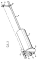
- Fig. 1 is a drawing of the arrangement of the laser, the mirror, a protractor and clamping mechanisms when the invention is used to align deflecting apparatus used in wells.
- Fig. 2 is a drawing showing the arrangement of the laser attached to a scribe shoe of a core barrel and the target attached to a survey tool used with the core barrel to obtain directional cores of rock from the earth.
- Fig. 3 is a close-up of the laser alignment system used with a core barrel.
- In these drawings the same reference signs denote the same or similar elements.
- So as illustrated in Fig. 1, an
elongated assembly 50 to be run into a well is comprised of an orientation-measuringinstrument 7, a firstelongate member 12, a secondelongate member 13, and adeflecting apparatus 40. Thedeflecting apparatus 40 can be any of a variety of tools run into wells which are to be oriented to a pre-selected azimuth direction in the well using the orientation-measuringinstrument 7,such instrument 7 having electrical cable connections (not shown) to the surface of the earth and providing a reading at the earth's surface of the orientation of theinstrument 7. The deflectingapparatus 40 can be a bent sub, a bent housing of a downhole motor, or other equipment. Theassembly 50 is adapted to be attached to a string of tubular members which is used to lower theassembly 50 into the well and to orient thedeflecting apparatus 40 in the pre-selected direction. The orientation-measuring instrument 7 is adapted to be lowered into the well through the string of tubular members until it seats into a receptacle (not shown) in the firstelongate member 12, using tecniques well-known in the art. The receptacle in the firstelongate member 12 is adapted to orient the orientation-measuringinstrument 7 in a determined angular relationship with respect to thedeflecting apparatus 40 using well-known techniques. The apparatus and method of the present invention are used to orient the orientation-measuringinstrument 7 and thedeflecting apparatus 40 in a known or preselected angular relationship with respect to each other while theassembly 50 is on the surface of the earth. - The
elongate members deflecting apparatus 40 are fixed together such that orientation with respect to each will not change in the well. The orientation-measuring instrument 7 is attached to the firstelongate member 12 using the receptacle in theelongate member 12. The receptacle orients the orientation-measuringinstrument 7 on a common axis with theelongate member 12 and in the direction in which it will orient with respect to the firstelongate member 12 in the well. Alaser 21 is clamped to the orientation-measuringinstrument 7 using aclamp 19. Theclamp 19 is constructed such that afirst reference mark 28 on the side of theclamp 19 is on the same radius from the common axis as the center of the laser beam. Aprotractor 22 having a line or group of lines, is attached to theinstrument 7 such that a reference line extends from thelaser 21 to the orientation-measuring instrument 7. Amirror 31 having a reference mark orreticle 32 is clamped to thedeflecting apparatus 40 using aclamp 35. Theclamp 35 is constructed such that asecond reference mark 38 on the side of theclamp 35 is on the same radius as the center of thereticle 32 or of a reference mark on themirror 31. - The distance between the
laser 21 and themirror 31 is determined by the total length of theelongate members laser 21 and ambient light conditions. Low power lasers are used to minimize danger of damage to the eyes of operators of the apparatus. - The
clamp 35 is adjusted such that thesecond reference mark 38 is precisely aligned with areference line 8 on thedeflecting apparatus 40. Theclamp 19 is then moved circumferentially around the orientation-measuring instrument 7 until the laser beam is precisely centered on thereticle 32. The reflection of the beam should also be centered on the line onplate 22 which extends between thelaser 21 and theinstrument 7. Theinstrument 7 is then used to measure the angle between the sensors in theinstrument 7 and the vertical force of gravity. This so-called "tool face angle" is then used as the reference angle to measure the direction of thedeflecting apparatus 40. The tool face angle is the angle between the radius connecting the common axis to the center of the laser beam and the force of gravity. Alternatively, a device allowing rotation of the receptacle (not shown) in thespacer 12 is used to rotate theinstrument 7 until the reference tool face angle is zero and theinstrument 7 is re-fixed at this angle. Theclamps plate 22 are removed and theassembly 50 is aligned and ready to be run into a well. - In Fig. 2, a cut-away drawing of a directional
core barrel assembly 10 containing an outer barrel 1 and aninner barrel 2 is shown. Theinner barrel 2 has attached thereto ascribe shoe 23 which includes aprincipal scribe 24 for marking a V-shaped notch in the core of rock as it enters theinner core barrel 2 after being cut from the earth by abit 25, using techniques well-known in the art. While aligning the totalcore barrel assembly 10 to be run into a well, aclamp 20 is attached to theinner core barrel 2. Theclamp 20 is comprised of abase 26 to fit within thescribe shoe 23 and a support for thelaser 21, such that the center of the laser beam is precisely located along the same radius from the center of thebase 26 of theclamp 20 as the principal notch in the scribe-shoe 23. Aprotractor 22 is also attached to theclamp 20. Anextension rod 3 and aspacer bar 4 allow- the orientation-measuring instrument 7 to be located a sufficient distance from the metal in the core barrel such that interference with the magnetic field of the earth is minimized and accurate measurements of the earth is minimized and accurate measurements of orientation of theinstrument 7 are made using the magnetic field of the earth. Anon-magnetic steel stabilizer 5 and anorienting bull plug 6 are often placed between thespacer bar 4 and theinstrument 7. While aligning the totalcore barrel assembly 10 to be run into a well, amirror 31 containing areticle 32 is attached to thespacer bar 4 by theclamp 30. - The
mirror 31 is moved circunferentially around thespacer bar 4, using theclamp 30, until the beam from thelaser 21 is directly centered on thereticle 32. Theinstrument 7 is then used to measure the tool face angle of themirror 31, which is the same as that of thelaser 21, which is the same as that of theprincipal scribe 24 in thescribe shoe 23. The angle measured is the reference angle in all subsequent measurements made in the well with theinstrument 7. Alternatively, the orientingbull plug 6 between theinstrument 7 and thespacer bar 4 is adjusted and theinstrument 7 is rotated until the tool face angle measures zero. This angle then becomes the reference angle. The tool face angle in this case is the angle between the radius connecting the common axis to themark 32 on themirror 31 and the force of gravity. - In Fig. 3, a schematic close-up of the alignment system shows the
laser 21, thetarget mirror 31, and theprotractor 22. Thelaser 21 can be moved by loosening aset screw 37 and rotating anarm 36 around apin 29. Thelaser 21 is set at the same angle on theprotractor 22 as the angle of theprincipal scribe 24 of the base of the clamp (not shown). Normally this is zero degrees. Thetarget mirror 31 is moved until the beam is centered on the target. The target is amirror 31 having areticle 32 attached thereto. Alternatively, the target is an optical receiver capable of emitting an audible signal which varies with intensity of incident light from thelaser 21. Such targets are available from Spectra Physics Corporation under the trade name LASERPLANE. Preferably, a device such as Model No. 350 is used as the target if an audible signal is preferred. - The
laser 21 is preferably a low power laser, from 0.5 to 3.0 milliwatt. Safety to operators is the primary consideration in limiting the power of thelaser 21. The beam diameter should be small, preferably less than 1 millimeter, and the divergence of the beam should be less than 2 milliradians. A 2 milliwatt helium-neon laser such as Model 1003, available from Uniphase of Manteca, California is suitable. Normally, a power supply operated by 110 volt power is used. Alternatively, thelaser 21 is operated by battery power. Asuitable mirror 31 andreticle 32 are available from Edmund Scientific Company of Barrington, New Jersey. If the distance between thelaser 21 and the target is more than 20 feet, it is preferable to place a "beam expander" in the laser beam and focus the lenses of the device to minimize beam diameter at the target. Such devices are available from Edmund Scientific Company. - Having described the invention above, various modifications of the techniques, procedures, material and equipment will be apparent to those in the art. It is intended that all such variations within the scope of the appended claims be embraced thereby.
The apparatus and method is particularly useful for aligning the scribe used to mark cores entering a core barrel and a survey instrument used in the well which measures and records orientation of the instrument. The laser is attached at the lower end of the core barrel by a clamp which places the laser precisely above the principal scribe knife of the barrel. The clamp and mirror are placed on gear which is rigidly fixed to the orientation-measuring instrument. The laser is powered up and the clamp holding the mirror is moved until the laser beam is precisely centered on the reference point of the graduated scale. The adjustment is checked by verifying that the beam is reflected back to the line between the laser and the core barrel. The coordinates of the instrument are then measured and recorded and the coordinates of the principal scribe shoe of the barrel, aligned with the instrument, will be measured when coordinates of the instrument are measured in the well. The scribe line, formed on a core of rock as it enters the core barrel, is then used to orient the direction of the rock before it was removed from the earth.
Claims (8)
- Apparatus for aligning on a common axis at least two spaced-apart elongate members (12, 13) of an elongate assembly to be run into a well in a predetermined angular relationship, said apparatus comprising :i) an orientation-measuring instrument (7) attached to the first elongate member (12) by means of a receptacle in the first elongate member (12) such that the first elongate member (12) and the orientation-measuring instrument (7) are aligned on the common axis, the orientation-measuring instrument (7) being attached to the first elongate member (12) at the end opposite to the second elongate member (13);ii) a laser (21) clamped to the orientation-measuring instrument (7) by a first clamp (19) rotatable about the common axis, for producing a beam of light directed parallel to the common axis, wherein the clamp (19) is constructed such that a first reference mark (28) referring on the side of the clamp to a mark indicating a principal scribe knife (24) location is on the same radius from the common axis as the centre of the laser beam;iii) a protractor (22) having a line or group of lines, attached to the instrument (7) such that a reference line of the protractor extends from the laser (21) to the first reference mark (28);iv) a mirror (31) provided with a reference mark (32), which is clamped to the second elongate member (13) using a second clamp (35) circumferentially movable around the second elongate member (13) in order to center the laser beam precisely on the reference mark (32) of the mirror (31), wherein the second clamp (35) is provided with a second reference mark (38) which is precisely aligned with a reference line (8) on the second elongate member (13),
said mirror (31) being attached to said second clamp such that the reference mark (32) of the mirror and the second reference mark (38) are on the same radius from the common axis, said mirror (31) being arranged perpendicular to the common axis such that in use the reflection of the laser beam is centered on the reference line of the protractor (22) which extends from the laser (21) to the first reference mark (28). - The apparatus according to claim 1, characterized in that it comprises further a lens in the beam of light for decreasing the diameter of the beam at said mirror (31).
- The apparatus according to claim 1 or 2, characterized in that said laser (21) has a power between 0.5 milliwatt and 3.0 milliwatt.
- The apparatus according to anyone of the preceding claims, characterized in that said laser (21) produces a beam with a diameter less than 1 mm and a beam divergence less than 2 milliradians.
- Apparatus according to anyone of the preceding claims, characterized in that the first elongate member (12) is a scribe shoe (23) having a principal scribe knife (24) thereon and the second elongate member (13) is an orientation-measuring instrument (7) used with a coring apparatus.
- Apparatus according to anyone of the preceding claims, characterized in that the mirror (31) comprises means for producing an audible signal when the beam is directed onto said mirror (31).
- Method for forming a scribe line on a core of rock as it enters the core barrel (2) in order to orient the direction of the rock before it is removed from the earth, by means of an apparatus according to anyone of preceding claims, in which a laser (21) produces a beam towards a mirror (31) provided with a reference mark (32), whereby the apparatus comprises at least two spaced apart elongate members (12, 13), said laser (21) being attached to an orientation-measuring instrument (7) attached to the end of a first elongate member (12), while the mirror (31) is clamped to a second elongate member (13), said method comprising the steps of :i) attaching an orientation-measuring instrument (7) to the end of first elongate member (12) opposite to the second elongate member (13) by using a receptacle in the first elongate member (12) in such manner that the first elongate member (12) and the orientation-measuring instrument (7) are aligned on a common axis;ii) attaching the laser (21) to the orientation-measuring instrument (7) above the principal scribe knife (24) of the core barrel (2) by means of a first clamp (19) rotatable about the common axis, whereby a first reference mark (28) on a side of the first clamp (19) is placed on the same radius from the common axis as the center of the laser beam so that the beam of light produced by the laser (21) is aligned parallel to the common axis;iii) adjusting the angular position of the mirror (31) until the beam of the laser (21) is centered on the reference mark (32) of the mirror (31) and until the beam is reflected back onto a line between the laser (21) and the first reference mark (28), andiv) marking on the secona elongate member (13) the location corresponding to the adjusted position of the mirror (31).
- The method according to claim 7, further comprising the step of :
placing a lens in the laser beam to decrease the diameter of a light beam from the laser (21).
Applications Claiming Priority (2)
| Application Number | Priority Date | Filing Date | Title |
|---|---|---|---|
| US07/566,620 US5084980A (en) | 1990-08-13 | 1990-08-13 | Laser alignment system for well equipment |
| US566620 | 1990-08-13 |
Publications (2)
| Publication Number | Publication Date |
|---|---|
| EP0471659A1 EP0471659A1 (en) | 1992-02-19 |
| EP0471659B1 true EP0471659B1 (en) | 1995-10-18 |
Family
ID=24263662
Family Applications (1)
| Application Number | Title | Priority Date | Filing Date |
|---|---|---|---|
| EP91870123A Expired - Lifetime EP0471659B1 (en) | 1990-08-13 | 1991-08-12 | Laser alignment system for well equipment |
Country Status (6)
| Country | Link |
|---|---|
| US (1) | US5084980A (en) |
| EP (1) | EP0471659B1 (en) |
| CA (1) | CA2048967A1 (en) |
| DE (1) | DE69113922T2 (en) |
| DK (1) | DK0471659T3 (en) |
| NO (1) | NO303552B1 (en) |
Families Citing this family (27)
| Publication number | Priority date | Publication date | Assignee | Title |
|---|---|---|---|---|
| US5272814A (en) * | 1989-04-14 | 1993-12-28 | Key Bruce G | Device for defining a horizontal plane |
| US5234281A (en) * | 1992-01-15 | 1993-08-10 | Somero Enterprise, Inc. | Deflection indicating adjustable highway straight-edge |
| JP3100478B2 (en) * | 1992-10-27 | 2000-10-16 | 株式会社トプコン | Laser rotary irradiation device with reciprocating laser scanning system |
| US5465493A (en) * | 1994-06-02 | 1995-11-14 | Spectra-Physics Laserplane, Inc. | Pipe alignment apparatus and method using green light |
| US5621531A (en) * | 1995-04-03 | 1997-04-15 | Laser Alignment, Inc. | Self-aligning sewer pipe laser |
| FR2733602B1 (en) * | 1995-04-28 | 1997-05-30 | Sextant Avionique | HARMONIZATION DEVICE OF A HIGH HEAD LANDING COLLIMATOR |
| US5749452A (en) * | 1995-07-27 | 1998-05-12 | R.A. Hanson Company, Inc. | Mobile conveyor including alignment system |
| GB2307756B (en) * | 1995-11-28 | 1999-09-22 | Black & Decker Inc | An alignment device |
| US6154522A (en) * | 1999-02-11 | 2000-11-28 | Mcdonnell Douglas Corporation | Method, system and apparatus for aiming a device emitting a radiant beam |
| US6374507B1 (en) * | 2000-01-21 | 2002-04-23 | Rick A. Lehto | Alignment tool |
| US6708782B1 (en) * | 2002-08-02 | 2004-03-23 | James Turney | Method and apparatus for axial alignment of a mud motor's adjustable housing relative to the orientation sub's internal sleeve in a drill string |
| US20060137201A1 (en) * | 2004-12-23 | 2006-06-29 | Kimberly-Clark Worldwide, Inc. | Laser goniometer for measuring the angle of a surface |
| US7086163B1 (en) * | 2005-02-10 | 2006-08-08 | Valentin Makotinsky | Method and remote-controlled reflector device for layout axis lines during construction of a building in the absence of direct line of sight |
| US7861424B2 (en) * | 2006-11-13 | 2011-01-04 | Robert Bosch Tool Corporation | Pipe laser |
| US10323504B2 (en) * | 2016-05-26 | 2019-06-18 | Accu-Scribe LLC | Techniques for determining an angular offset between two objects |
| US10502561B2 (en) | 2010-04-08 | 2019-12-10 | Accu-Scribe LLC | Techniques for determining an angular offset between two objects |
| EP2950041B1 (en) * | 2013-01-25 | 2018-06-20 | The Chugoku Electric Power Co., Inc. | System and method for distance measurement |
| US10064700B2 (en) * | 2013-02-14 | 2018-09-04 | Zvi Fudim | Surgical guide kit apparatus and method |
| DE102013216172A1 (en) * | 2013-08-14 | 2015-03-12 | Bayerische Motoren Werke Aktiengesellschaft | Scharnierfluchtprüfeinrichtung |
| US10590725B2 (en) * | 2016-02-03 | 2020-03-17 | Lufkin Industries, Llc | Optical alignment system for beam pumping unit |
| CN105698712B (en) * | 2016-03-23 | 2017-11-03 | 西安科技大学 | A kind of two degrees of freedom measurement apparatus and method based on mirror imaging |
| NO343139B1 (en) * | 2017-07-13 | 2018-11-19 | Pipe Pilot As | Method for aligning pipes coaxially |
| WO2019173092A1 (en) * | 2018-03-05 | 2019-09-12 | Accu-Scribe LLC | Techniques for determining an angular offset between two objects |
| CN109186504A (en) * | 2018-09-29 | 2019-01-11 | 滁州欧博特电子制造有限公司 | A kind of device and its measurement method measuring guide rail linearity |
| CN110566213B (en) * | 2019-10-10 | 2024-08-23 | 浙江海聚科技有限公司 | Auxiliary device for centering drill rod of advanced drilling machine |
| IT201900020562A1 (en) * | 2019-11-07 | 2021-05-07 | Univ Degli Studi Milano | Device and method and for the measurement of the inclination and angular stability of electromagnetic radiation beams, and for the measurement of a spatial deviation of a focused electromagnetic radiation beam |
| WO2024076364A1 (en) * | 2022-10-05 | 2024-04-11 | Halliburton Energy Services, Inc. | Drill string angular offset determination |
Citations (1)
| Publication number | Priority date | Publication date | Assignee | Title |
|---|---|---|---|---|
| US2088539A (en) * | 1936-11-28 | 1937-07-27 | Eastman Oil Well Survey Co | Means and method of orienting deflecting tools in wells |
Family Cites Families (16)
| Publication number | Priority date | Publication date | Assignee | Title |
|---|---|---|---|---|
| US2735652A (en) * | 1956-02-21 | brady | ||
| US1830345A (en) * | 1924-08-15 | 1931-11-03 | Anderson Alexander | Bore hole directional apparatus and method of orientation |
| US1770224A (en) * | 1924-08-15 | 1930-07-08 | Anderson Alexander | Borehole directional apparatus and method of orientation |
| US2136689A (en) * | 1937-08-07 | 1938-11-15 | Eastman Oil Well Survey Co | Means and method of orienting pipe |
| US2971373A (en) * | 1957-07-05 | 1961-02-14 | Arthur P Heldenbrand | Method for minimizing drill pipe failures |
| US3059707A (en) * | 1959-10-02 | 1962-10-23 | Eastman Oil Well Survey Co | Method and apparatus for orienting cores |
| US3703682A (en) * | 1968-10-30 | 1972-11-21 | Us Navy | Long axis gradiometer |
| US3801205A (en) * | 1972-04-06 | 1974-04-02 | Pulfer Ag | Process and device for the survey alignment with a laser beam |
| US4150897A (en) * | 1977-03-02 | 1979-04-24 | FMC Corporaton | Wheel-mounted vehicle wheel aligner |
| US4141153A (en) * | 1977-08-03 | 1979-02-27 | Wilson Industries, Inc. | Bottom hole survey apparatus |
| US4518855A (en) * | 1982-09-30 | 1985-05-21 | Spring-Mornne, Inc. | Method and apparatus for statically aligning shafts and monitoring shaft alignment |
| DE3320163A1 (en) * | 1983-06-03 | 1984-12-13 | Prüftechnik Dieter Busch + Partner GmbH & Co, 8045 Ismaning | DEVICE FOR DETECTING ALIGNMENT FAULTS OF SHAFTS ARRANGED IN ADJUSTMENT |
| GB8429201D0 (en) * | 1984-11-19 | 1984-12-27 | Secr Defence | Alignment aid |
| JPS6238309A (en) * | 1985-08-13 | 1987-02-19 | Nippon Kokan Kk <Nkk> | Axis misalignment detection device |
| US4747454A (en) * | 1986-05-12 | 1988-05-31 | Perryman J Philip | External axis parallel alignment system |
| GB8719154D0 (en) * | 1987-08-13 | 1987-09-23 | Coal Industry Patents Ltd | Optically measuring relative angular movement |
-
1990
- 1990-08-13 US US07/566,620 patent/US5084980A/en not_active Expired - Fee Related
-
1991
- 1991-08-12 NO NO913125A patent/NO303552B1/en not_active IP Right Cessation
- 1991-08-12 CA CA002048967A patent/CA2048967A1/en not_active Abandoned
- 1991-08-12 EP EP91870123A patent/EP0471659B1/en not_active Expired - Lifetime
- 1991-08-12 DE DE69113922T patent/DE69113922T2/en not_active Expired - Fee Related
- 1991-08-12 DK DK91870123.6T patent/DK0471659T3/en active
Patent Citations (1)
| Publication number | Priority date | Publication date | Assignee | Title |
|---|---|---|---|---|
| US2088539A (en) * | 1936-11-28 | 1937-07-27 | Eastman Oil Well Survey Co | Means and method of orienting deflecting tools in wells |
Also Published As
| Publication number | Publication date |
|---|---|
| DE69113922D1 (en) | 1995-11-23 |
| US5084980A (en) | 1992-02-04 |
| DK0471659T3 (en) | 1996-03-04 |
| NO913125L (en) | 1992-02-14 |
| CA2048967A1 (en) | 1992-02-14 |
| NO303552B1 (en) | 1998-07-27 |
| NO913125D0 (en) | 1991-08-12 |
| DE69113922T2 (en) | 1996-05-02 |
| EP0471659A1 (en) | 1992-02-19 |
Similar Documents
| Publication | Publication Date | Title |
|---|---|---|
| US5084980A (en) | Laser alignment system for well equipment | |
| US7987605B2 (en) | Reflector target tripod for survey system with light emitter and pivoting bracket for enhanced ground marking accuracy | |
| US3588255A (en) | Optical alignment methods and means utilizing coordinated laser beams and laser beam coordinating means for same | |
| AU2014286916B2 (en) | Alignment system for alignment of a drill rod during drilling | |
| EP1929125B1 (en) | System for tracking and maintaining an on-grade horizontal borehole | |
| US3894805A (en) | Mounting apparatus and system for laser surveying instrument | |
| US20150204149A1 (en) | Laser alignment device for use with a drill rig | |
| US7631434B1 (en) | Plumb/level alignment gauge for aligning structural elements in two directions | |
| US3612700A (en) | Laser beam reference line means and method | |
| US6659196B1 (en) | Core orientation | |
| GB2154387A (en) | Locating mobile cutting means | |
| KR101550403B1 (en) | the improved portable prism receiver and the improved portable GPS receiver and the measurement method using the same | |
| US20250231027A1 (en) | Survey mark | |
| US5189799A (en) | Laser goniometer | |
| US4754553A (en) | One-man field survey instrument | |
| US4972591A (en) | Method and device for land surveying | |
| AU602142B2 (en) | Distance measuring method and means | |
| GB2277150A (en) | A portable measuring device for determining the versines of a railway track | |
| US5469301A (en) | Prism pod | |
| US3307264A (en) | Grading instruments | |
| US1830345A (en) | Bore hole directional apparatus and method of orientation | |
| US5639966A (en) | Machine height measuring method and machine height measuring device for surveying machines | |
| CN118168512B (en) | Power line height measuring device | |
| CN220398567U (en) | One-well orientation measurement device based on laser height measurement | |
| US2785466A (en) | Stadia topograph |
Legal Events
| Date | Code | Title | Description |
|---|---|---|---|
| PUAI | Public reference made under article 153(3) epc to a published international application that has entered the european phase |
Free format text: ORIGINAL CODE: 0009012 |
|
| AK | Designated contracting states |
Kind code of ref document: A1 Designated state(s): BE DE DK FR GB NL |
|
| 17P | Request for examination filed |
Effective date: 19920424 |
|
| 17Q | First examination report despatched |
Effective date: 19931109 |
|
| GRAA | (expected) grant |
Free format text: ORIGINAL CODE: 0009210 |
|
| AK | Designated contracting states |
Kind code of ref document: B1 Designated state(s): BE DE DK FR GB NL |
|
| REF | Corresponds to: |
Ref document number: 69113922 Country of ref document: DE Date of ref document: 19951123 |
|
| ET | Fr: translation filed | ||
| REG | Reference to a national code |
Ref country code: DK Ref legal event code: T3 |
|
| PLBE | No opposition filed within time limit |
Free format text: ORIGINAL CODE: 0009261 |
|
| STAA | Information on the status of an ep patent application or granted ep patent |
Free format text: STATUS: NO OPPOSITION FILED WITHIN TIME LIMIT |
|
| 26N | No opposition filed | ||
| PGFP | Annual fee paid to national office [announced via postgrant information from national office to epo] |
Ref country code: DK Payment date: 19980615 Year of fee payment: 8 |
|
| PG25 | Lapsed in a contracting state [announced via postgrant information from national office to epo] |
Ref country code: DK Free format text: LAPSE BECAUSE OF NON-PAYMENT OF DUE FEES Effective date: 19990812 |
|
| REG | Reference to a national code |
Ref country code: DK Ref legal event code: EBP |
|
| PGFP | Annual fee paid to national office [announced via postgrant information from national office to epo] |
Ref country code: NL Payment date: 20000620 Year of fee payment: 10 |
|
| PGFP | Annual fee paid to national office [announced via postgrant information from national office to epo] |
Ref country code: GB Payment date: 20000703 Year of fee payment: 10 |
|
| PGFP | Annual fee paid to national office [announced via postgrant information from national office to epo] |
Ref country code: FR Payment date: 20000803 Year of fee payment: 10 |
|
| PGFP | Annual fee paid to national office [announced via postgrant information from national office to epo] |
Ref country code: DE Payment date: 20000830 Year of fee payment: 10 |
|
| PGFP | Annual fee paid to national office [announced via postgrant information from national office to epo] |
Ref country code: BE Payment date: 20000915 Year of fee payment: 10 |
|
| PG25 | Lapsed in a contracting state [announced via postgrant information from national office to epo] |
Ref country code: GB Free format text: LAPSE BECAUSE OF NON-PAYMENT OF DUE FEES Effective date: 20010812 |
|
| PG25 | Lapsed in a contracting state [announced via postgrant information from national office to epo] |
Ref country code: BE Free format text: LAPSE BECAUSE OF NON-PAYMENT OF DUE FEES Effective date: 20010831 |
|
| BERE | Be: lapsed |
Owner name: ORYX ENERGY CY Effective date: 20010831 |
|
| PG25 | Lapsed in a contracting state [announced via postgrant information from national office to epo] |
Ref country code: NL Free format text: LAPSE BECAUSE OF NON-PAYMENT OF DUE FEES Effective date: 20020301 |
|
| GBPC | Gb: european patent ceased through non-payment of renewal fee |
Effective date: 20010812 |
|
| PG25 | Lapsed in a contracting state [announced via postgrant information from national office to epo] |
Ref country code: FR Free format text: LAPSE BECAUSE OF NON-PAYMENT OF DUE FEES Effective date: 20020430 |
|
| NLV4 | Nl: lapsed or anulled due to non-payment of the annual fee |
Effective date: 20020301 |
|
| PG25 | Lapsed in a contracting state [announced via postgrant information from national office to epo] |
Ref country code: DE Free format text: LAPSE BECAUSE OF NON-PAYMENT OF DUE FEES Effective date: 20020501 |
|
| REG | Reference to a national code |
Ref country code: FR Ref legal event code: ST |