EP0471458B1 - Molded suture retainer - Google Patents
Molded suture retainer Download PDFInfo
- Publication number
- EP0471458B1 EP0471458B1 EP91306707A EP91306707A EP0471458B1 EP 0471458 B1 EP0471458 B1 EP 0471458B1 EP 91306707 A EP91306707 A EP 91306707A EP 91306707 A EP91306707 A EP 91306707A EP 0471458 B1 EP0471458 B1 EP 0471458B1
- Authority
- EP
- European Patent Office
- Prior art keywords
- suture
- passageway
- retainer
- vacuum
- curved section
- Prior art date
- Legal status (The legal status is an assumption and is not a legal conclusion. Google has not performed a legal analysis and makes no representation as to the accuracy of the status listed.)
- Expired - Lifetime
Links
Images


Classifications
-
- A—HUMAN NECESSITIES
- A61—MEDICAL OR VETERINARY SCIENCE; HYGIENE
- A61B—DIAGNOSIS; SURGERY; IDENTIFICATION
- A61B17/00—Surgical instruments, devices or methods, e.g. tourniquets
- A61B17/04—Surgical instruments, devices or methods, e.g. tourniquets for suturing wounds; Holders or packages for needles or suture materials
- A61B17/06—Needles ; Sutures; Needle-suture combinations; Holders or packages for needles or suture materials
- A61B17/06114—Packages or dispensers for needles or sutures
- A61B17/06133—Packages or dispensers for needles or sutures of parallelepipedal shape, e.g. made of rectangular or slightly oval panels
Definitions
- the present invention relates to packaging of sutures and, more particularly, to an improved package and method of packaging sutures to improve handling characteristics thereof.
- a suture retainer in accordance with the pre-characterising part of claim 1 is disclosed in US-A-3,338,401.
- This invention relates to molded suture retainers and their use for packaging sutures, including nonabsorbable and synthetic absorbable sutures, to improve the out of package flexibility and handling characteristics of the sutures after storage.
- Sutures can be either monofilament or braided and are available in a wide variety of materials including cotton, silk, stainless steel, catgut, and dacron, nylon or other synthetic materials.
- Synthetic absorbable sutures are typically formed using polymers and copolymers of glycolic acid (i.e., hydroxyacetic acid), the cyclic dimer of glycolic acid (“glycolide”), lactic acid, the cyclic dimer of lactic acid (“lactide”) and related monomers, polydioxanone, polytrimethylene carbonate, polyalkylene glycol, polycaprolactone, their copolymers, etc.
- glycolic acid i.e., hydroxyacetic acid
- glycolic acid i.e., hydroxyacetic acid
- glycolide the cyclic dimer of glycolic acid
- lactide the cyclic dimer of lactic acid
- related monomers polydioxanone, polytrimethylene carbonate, polyalkylene glycol, polycaprolactone, their copolymers, etc.
- Nonabsorbable sutures may be packaged and/or sterilized using conventional techniques without concern for degradation of the suture material through hydrolysis.
- Synthetic absorbable sutures typically are packaged in moisture impervious foil laminate envelopes wherein the suture is wound in a figure 8 pattern on a paper retainer. Typical retainers of this type are shown in U.S. Patent Nos. 4,249,656, 4,253,563, and 4,063,638.
- Molded suture packages having narrow convoluted passageways configured to predetermine the coil of the suture are also known.
- U.S. Patent Nos. 3,338,401 and 3,490,192 disclose molded suture packages wherein one or more elongated sutures are retained in a coiled narrow passageway having a plurality of convolutions therein. These passageways are proportioned to accommodate an entire length of the suture end to end without folding. These passageways are typically molded into a plastic carrier material and define a small diameter hollow plastic tube.
- the patents also discuss the loading of sutures into the passageways using a vacuum. Molded retainers have been used to package nonabsorbable sutures, but have not been adopted for widespread use in packaging sutures.
- Typical commercially available synthetic absorbable sutures are packaged under extremely dry conditions, and are relatively stiff and inflexible upon removal from the packaging. Such sutures exhibit "memory" which causes the suture to retain or resume the customary figure 8 or coiled shape assumed by sutures packaged in such a configuration in a cardboard or paper retainer. This effect is undesirable since the suture must be straightened prior to use. The figure 8 configuration has also been found to introduce undesirable kinks and bends in the suture. It is believed that the extremely dry conditions required for packaging prior synthetic absorbable sutures, together with the suture memory effect created by such packaging and the number and radius of curvature of the convolutions required to accommodate full length sutures may combine to make it difficult or impossible to withdraw the suture from such packaging without breaking the suture. This is particularly believed to be true in the case of sutures having lengths in excess of 50 cm (20 inches) wherein the passageways must be extremely compressed and convoluted in order to accommodate the suture end to end.
- a molded suture retainer for retaining and storing sutures constructed of natural or synthetic materials including both absorbable and nonabsorbable sutures.
- the retainer comprises a molded member defining a wide passageway open at the top and sufficient for holding a plurality of strands of sutures therein.
- the passageway is formed in an oval racetrack configuration spiraling toward the interior of the retainer with a minimum number of convolutions.
- the length of the passageway is preferably proportional to 1/3 to 1/2 the overall length of the suture to be retained therein. Other proportions are also contemplated.
- One end of the passageway serves as a suture receiving section to facilitate loading of the sutures.
- a vacuum receiving section is placed at the opposite end of the passageway to allow a vacuum to be drawn through the passageway to help position the sutures therein.
- the present invention contemplates the loading and storage of both armed sutures, i.e. sutures having needles attached thereto, and unarmed sutures without needles attached.
- the suture is advantageously folded prior to positioning within the passageway.
- the suture preferably is folded either in half or in thirds. Where exceptionally long sutures are contemplated, folding can be in fourths or fifths or close approximations thereof.
- a cover sheet is used to overlie the open top of the retainer.
- the cover sheet has a vacuum aperture and suture entrance aperture formed therein.
- the vacuum aperture aligns and communicates with the vacuum receiving section of the passageway while the suture entrance aperture aligns and communicates with the suture receiving section of the passageway.
- special needle holding sections or a foam needle part can be added to the retainer for convenient needle positioning.
- the cover sheet may also include a fold over section to cover the needle when packaged, but which is moved to an open position upon opening the outer pouch in order to reveal the needle.
- loading is accomplished by folding the suture and feeding the end opposite the needle into the suture entrance aperture.
- a vacuum is drawn on the passageway adjacent the vacuum aperture and serves to draw the folded suture into the passageway.
- Fig. 1 there is shown a plan view of a molded suture retainer 20 in accordance with the invention.
- the molded suture retainer illustrated in Fig. 1 finds particular application for holding double or triple folded sutures of up to or more than 91 cm (36 inches) in length.
- the molded suture retainer is made from a moldable transparent plastic material such as, for example, polyethylene terapthalate (PETG), Eastman Kodak 6763.
- PETG polyethylene terapthalate
- Eastman Kodak 6763 Eastman Kodak
- retainer 20 has a base 22 and an enlarged suture receiving section 24 leading to a relatively wide passageway 26 having minimal convolutions.
- the passageway 26 follows an oval pattern spiraling toward the proximate center through four turns and terminates at a central vacuum receiving section 28.
- Fig. 2 is a cross-sectional view of the retainer shown in Fig. 1 taken along line 2-2 of Fig. 1, illustrating base 22 with molded passageway 26 extending from the base 22.
- base 22 is approximately 3.350 inches (85.09 millimeters) by 1.375 inches (34.925 millimeters) in order to conform to commonly accepted overall dimensions of conventional suture packages and display boxes.
- the retainers are preferably about .010 inches (.254 millimeters) thick.
- Passageway 26 is substantially wider than conventional molded suture retainer passageways and should be at least several times the diameter of the largest suture to be disposed therein. Preferably the passageway is at least about twice the diameter of the largest suture to be placed therein in depth and at least about four times the diameter in width. This relatively wide passageway 26 permits the easy insertion, storage and removal of folded sutures without the creation of undesirable kinks and bends in the suture. Depending on the size of the base and the number of sutures to be retained, the passageway may be made wider and, if necessary, deeper.
- width ranges of between about .10 and .30 inches and depth ranges of between about .05 and .07 inches are contemplated.
- a passageway of about .060 inches (1.524 millimeters) deep and .200 inches (5.080 millimeters) wide is preferred (see Fig. 2).
- cover sheet 30 for the retainer shown in Figs. 1 and 2.
- Cover sheet 30 is configured and dimensioned to overlie the open top of the retainer 20.
- the cover sheet is provided with a vacuum aperture 32 and a suture entrance aperture 34.
- Cover sheet 30 is adhesively attached to the molded retainer 20 and covers the passageway 26.
- the cover sheet is adhered to the retainer with a hot melt adhesive, such as Oliver 18B adhesive coating available from Oliver Products of Minneapolis, Minnesota.
- Vacuum aperture 32 aligns and communicates with the central vacuum receiving section 28 of the molded retainer 20.
- suture entrance aperture 34 aligns and communicates with the suture receiving section 24.
- Cover sheet 20 is constructed of a material which is pervious to ethylene oxide sterilizing gas.
- the preferred material is a spun bonded polyolefin, such as Tyvek 1073B available from E.I. DuPont de Nemours & Co.
- the preferred cover sheet 30 includes a fold-over panel 36 joined to the main section of the cover sheet at a perforated score line 38 with openings 40.
- a foam needle park 42 can be provided for holding a needle 43 in place during storage.
- passageway 26 is shown in phantom to illustrate the relationship of the cover sheet to the molded retainer.
- Retainer 20 is well suited for doubled over or doubled armed sutures and is preferred for tripled over sutures.
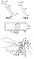
- a suture 44 such as a suture which is thirty six or more inches in length, is looped to form a first curved or half loop section 46 distal to the needle 48 and a second curved or half loop section 50 adjacent the needle.
- a suture tail end 52 extends beyond the first curved section 46.
- tail end 52 extends beyond first curved loop section by a distance of at least about one inch.
- suture tail end 52 and then first curved section 46 are sequentially inserted through suture entrance aperture 34 into passageway 26 while holding the suture adjacent the needle 48 and the second curved section 50.
- the suture is drawn into the retainer 20 by vacuum until the needle 48 is disposed adjacent suture aperture 34.
- suture tail end 52 extend beyond the first curved section 46 at all times so that a knot is not inadvertently formed in the suture during insertion or removal from the retainer.
- Fig. 5 shows a bottom view of an unarmed tripled over suture 44 loaded within the wide passageway 26 of the molded suture retainer 20.
- the suture 54 is looped proximate its midpoint 56 to form two approximately equal lengths. Loading is accomplished in a manner similar to that described above with respect to the tripled over suture with the exception that no extended suture tail end need be formed.
- needle 58 and suture end 60 are grasped while inserting midpoint suture loop 56 through suture entrance aperture 34 into passageway 26.
- the suture 54 is drawn into the retainer 20 by vacuum until the needle is disposed adjacent the suture aperture 34.
- one needle could be disposed in the needle park prior to drawing the suture into the retainer under vacuum. That is, one needle would be placed in the needle park with the blunt end of the needle adjacent suture entrance aperture 34, then the suture would be drawn into the retainer under vacuum until the second needle is also adjacent the suture entrance aperture and can similarly be placed in the needle park.
- cover sheet 30 preferably includes a fold over panel 36.
- Fold over panel 36 covers the needle and suture during storage and is moved to an open position upon opening the outer package containing the suture and retainer.
- the suture and retainer may simply be enclosed in a so-called breather pouch suitable for gas sterilization, such as a pouch consisting on one side of polyolefin (Tyvek) and a clear plastic on the other, such as polyethylene.
- the breather pouch is opened by peeling the two sides of the breather pouch apart and opening the fold over panel to reveal the needle or suture end, which may be grasped to remove the suture from the retainer by pulling.
- the retainer would be packaged in a foil laminate envelope which would be further packaged within an outer breather pouch.
- the preferred inner pouch is the peelable pouch as shown in Figs. 7 and 8.
- Fig. 7 is a top plan view of the preferred peelable pouch in the closed position, and
- Fig. 8 illustrates the pouch partially peeled open.
- the peelable inner pouch 45 has a top layer comprised of first and second top panels 47, 49, respectively.
- the first and second top panels are adhered to each other transversely, leaving a gripping tab 51.
- the top panels are adhered to a bottom panel 55 at a peripheral seal 53, i.e. at the transverse and longitudinal edges of the inner pouch or envelope, so as to define a pocket for receiving a suture retainer.
- first top panel 47 does not extend the full length of bottom panel 55, but terminates at a first top panel transverse edge 57.
- top panels 47, 49 and bottom panel 55 may be constructed of a foil laminate material with a hot melt adhesive on the inner surface of each panel for forming peripheral seal 53 and the seal between the overlapping first and second top layer panels.
- peelable pouch is preferred, but it will be understood that other types of envelopes, such as conventional tearable foil laminate envelopes, can be used. See, for example, U.S. Patent Nos. 3,939,969 and 4,014,433. It is contemplated that the suture could be sterilized by ethylene oxide permeating through an opening in the peelable pouch which is subsequently sealed, and that the peelable pouch itself should be sterilized and maintained sterile in an outer breather pouch in a known manner. See, for example, U.S. Patent Nos. 3,815,315 and 4,603,538.
Description
- The present invention relates to packaging of sutures and, more particularly, to an improved package and method of packaging sutures to improve handling characteristics thereof. A suture retainer in accordance with the pre-characterising part of claim 1 is disclosed in US-A-3,338,401.
- This invention relates to molded suture retainers and their use for packaging sutures, including nonabsorbable and synthetic absorbable sutures, to improve the out of package flexibility and handling characteristics of the sutures after storage. Sutures can be either monofilament or braided and are available in a wide variety of materials including cotton, silk, stainless steel, catgut, and dacron, nylon or other synthetic materials.
- Synthetic absorbable sutures are typically formed using polymers and copolymers of glycolic acid (i.e., hydroxyacetic acid), the cyclic dimer of glycolic acid ("glycolide"), lactic acid, the cyclic dimer of lactic acid ("lactide") and related monomers, polydioxanone, polytrimethylene carbonate, polyalkylene glycol, polycaprolactone, their copolymers, etc.
- Nonabsorbable sutures may be packaged and/or sterilized using conventional techniques without concern for degradation of the suture material through hydrolysis. Synthetic absorbable sutures, in contrast, typically are packaged in moisture impervious foil laminate envelopes wherein the suture is wound in a figure 8 pattern on a paper retainer. Typical retainers of this type are shown in U.S. Patent Nos. 4,249,656, 4,253,563, and 4,063,638.
- Molded suture packages having narrow convoluted passageways configured to predetermine the coil of the suture are also known. For example, U.S. Patent Nos. 3,338,401 and 3,490,192 disclose molded suture packages wherein one or more elongated sutures are retained in a coiled narrow passageway having a plurality of convolutions therein. These passageways are proportioned to accommodate an entire length of the suture end to end without folding. These passageways are typically molded into a plastic carrier material and define a small diameter hollow plastic tube. The patents also discuss the loading of sutures into the passageways using a vacuum. Molded retainers have been used to package nonabsorbable sutures, but have not been adopted for widespread use in packaging sutures.
- Typical commercially available synthetic absorbable sutures are packaged under extremely dry conditions, and are relatively stiff and inflexible upon removal from the packaging. Such sutures exhibit "memory" which causes the suture to retain or resume the customary figure 8 or coiled shape assumed by sutures packaged in such a configuration in a cardboard or paper retainer. This effect is undesirable since the suture must be straightened prior to use. The figure 8 configuration has also been found to introduce undesirable kinks and bends in the suture. It is believed that the extremely dry conditions required for packaging prior synthetic absorbable sutures, together with the suture memory effect created by such packaging and the number and radius of curvature of the convolutions required to accommodate full length sutures may combine to make it difficult or impossible to withdraw the suture from such packaging without breaking the suture. This is particularly believed to be true in the case of sutures having lengths in excess of 50 cm (20 inches) wherein the passageways must be extremely compressed and convoluted in order to accommodate the suture end to end.
- Therefore, it would be highly desirable to provide a molded suture retainer and method of loading same which permits the suture to be stored more efficiently without the introduction of kinks and bends.
- According to the present invention, a molded suture retainer is provided for retaining and storing sutures constructed of natural or synthetic materials including both absorbable and nonabsorbable sutures. The retainer comprises a molded member defining a wide passageway open at the top and sufficient for holding a plurality of strands of sutures therein. The passageway is formed in an oval racetrack configuration spiraling toward the interior of the retainer with a minimum number of convolutions. The length of the passageway is preferably proportional to 1/3 to 1/2 the overall length of the suture to be retained therein. Other proportions are also contemplated.
The claims which follow identify various aspects of the invention, all linked by the concept that the retainer is accommodated within an outer package, and in that the retainer combines a molded channel member and a cover sheet made of a material which is pervious to sterilising gas. - One end of the passageway serves as a suture receiving section to facilitate loading of the sutures. A vacuum receiving section is placed at the opposite end of the passageway to allow a vacuum to be drawn through the passageway to help position the sutures therein.
- The present invention contemplates the loading and storage of both armed sutures, i.e. sutures having needles attached thereto, and unarmed sutures without needles attached.
- In one embodiment of this invention, the suture is advantageously folded prior to positioning within the passageway. For double armed or long length sutures, the suture preferably is folded either in half or in thirds. Where exceptionally long sutures are contemplated, folding can be in fourths or fifths or close approximations thereof.
- A cover sheet is used to overlie the open top of the retainer. The cover sheet has a vacuum aperture and suture entrance aperture formed therein. The vacuum aperture aligns and communicates with the vacuum receiving section of the passageway while the suture entrance aperture aligns and communicates with the suture receiving section of the passageway. Where desired, special needle holding sections or a foam needle part can be added to the retainer for convenient needle positioning. The cover sheet may also include a fold over section to cover the needle when packaged, but which is moved to an open position upon opening the outer pouch in order to reveal the needle.
- For an armed suture, loading is accomplished by folding the suture and feeding the end opposite the needle into the suture entrance aperture. A vacuum is drawn on the passageway adjacent the vacuum aperture and serves to draw the folded suture into the passageway.
- The accompanying drawings, referred to herein and constituting a part hereof, illustrate the preferred embodiments of the product and method of the present invention, and together with the description serve to explain the principles of the invention, in which:
- Fig. 1 is a plan view of a preferred embodiment of a molded suture retainer in accordance with the present invention;
- Fig. 2 is a cross-sectional view of the retainer of Fig. 1 taken along lines 2-2;
- Fig. 3 is a plan view of a cover sheet for the molded suture retainer;
- Fig. 4 is an illustration of a tripled-over suture;
- Fig. 5 is a plan view of a molded suture retainer showing a tripled over suture loaded therein;
- Fig. 6 is an illustration of a doubled-over suture;
- Fig. 7 is a plan view in partial cross section of a suture retainer in accordance with another embodiment of the invention; and
- Fig. 8 is a plan view showing the opening procedure for a suture retainer in accordance with one embodiment of the invention.
- Referring now to Fig. 1, there is shown a plan view of a molded
suture retainer 20 in accordance with the invention. The molded suture retainer illustrated in Fig. 1 finds particular application for holding double or triple folded sutures of up to or more than 91 cm (36 inches) in length. Preferably, the molded suture retainer is made from a moldable transparent plastic material such as, for example, polyethylene terapthalate (PETG), Eastman Kodak 6763. - As shown,
retainer 20 has abase 22 and an enlargedsuture receiving section 24 leading to a relativelywide passageway 26 having minimal convolutions. Thepassageway 26 follows an oval pattern spiraling toward the proximate center through four turns and terminates at a centralvacuum receiving section 28. - Fig. 2 is a cross-sectional view of the retainer shown in Fig. 1 taken along line 2-2 of Fig. 1, illustrating
base 22 withmolded passageway 26 extending from thebase 22. Preferably,base 22 is approximately 3.350 inches (85.09 millimeters) by 1.375 inches (34.925 millimeters) in order to conform to commonly accepted overall dimensions of conventional suture packages and display boxes. The retainers are preferably about .010 inches (.254 millimeters) thick. - Typical sizes and diameters of sutures from the standard United States Pharmacopeia (United States Pharmacopeia Convention, Inc., elsewhere abbreviated U.S.P.) are listed below (1 inch = 2.54 cm).
U.S.P. Size U.S.P. Diameter, Inches, Max. 7-0 0.002 6-0 0.004 5-0 0.006 4-0 0.008 3-0 0.010 2-0 0.013 1-0 0.016 1 0.019 2 0.022 3 0.025 - While these sizes are most common, one skilled in the art would realize that other sizes can be used with the retainer of the present invention.
Passageway 26 is substantially wider than conventional molded suture retainer passageways and should be at least several times the diameter of the largest suture to be disposed therein. Preferably the passageway is at least about twice the diameter of the largest suture to be placed therein in depth and at least about four times the diameter in width. This relativelywide passageway 26 permits the easy insertion, storage and removal of folded sutures without the creation of undesirable kinks and bends in the suture. Depending on the size of the base and the number of sutures to be retained, the passageway may be made wider and, if necessary, deeper. For example, width ranges of between about .10 and .30 inches and depth ranges of between about .05 and .07 inches are contemplated. For most common suture sizes a passageway of about .060 inches (1.524 millimeters) deep and .200 inches (5.080 millimeters) wide is preferred (see Fig. 2). - Referring now to Fig. 3, there is shown an
appropriate cover sheet 30 for the retainer shown in Figs. 1 and 2. Coversheet 30 is configured and dimensioned to overlie the open top of theretainer 20. The cover sheet is provided with avacuum aperture 32 and asuture entrance aperture 34. Coversheet 30 is adhesively attached to the moldedretainer 20 and covers thepassageway 26. In a preferred embodiment the cover sheet is adhered to the retainer with a hot melt adhesive, such as Oliver 18B adhesive coating available from Oliver Products of Minneapolis, Minnesota. -
Vacuum aperture 32 aligns and communicates with the centralvacuum receiving section 28 of the moldedretainer 20. Similarly,suture entrance aperture 34 aligns and communicates with thesuture receiving section 24. Coversheet 20 is constructed of a material which is pervious to ethylene oxide sterilizing gas. The preferred material is a spun bonded polyolefin, such as Tyvek 1073B available from E.I. DuPont de Nemours & Co. - As shown in Fig. 3, the
preferred cover sheet 30 includes a fold-overpanel 36 joined to the main section of the cover sheet at aperforated score line 38 withopenings 40. Where armed sutures are to be loaded, afoam needle park 42 can be provided for holding aneedle 43 in place during storage. In Fig. 3,passageway 26 is shown in phantom to illustrate the relationship of the cover sheet to the molded retainer.Retainer 20 is well suited for doubled over or doubled armed sutures and is preferred for tripled over sutures. - Referring to Fig. 4, in order to load a tripled over suture into the
retainer 20 of Figs. 1 and 2, asuture 44, such as a suture which is thirty six or more inches in length, is looped to form a first curved orhalf loop section 46 distal to theneedle 48 and a second curved orhalf loop section 50 adjacent the needle. Asuture tail end 52 extends beyond the firstcurved section 46. Preferably,tail end 52 extends beyond first curved loop section by a distance of at least about one inch. - With vacuum applied to the retainer, such as by placing a vacuum block (not shown) over vacuum aperture 32 (see Fig. 3),
suture tail end 52 and then firstcurved section 46 are sequentially inserted throughsuture entrance aperture 34 intopassageway 26 while holding the suture adjacent theneedle 48 and the secondcurved section 50. The suture is drawn into theretainer 20 by vacuum until theneedle 48 is disposedadjacent suture aperture 34. In this embodiment, it is important thatsuture tail end 52 extend beyond the firstcurved section 46 at all times so that a knot is not inadvertently formed in the suture during insertion or removal from the retainer. Fig. 5 shows a bottom view of an unarmed tripled oversuture 44 loaded within thewide passageway 26 of the moldedsuture retainer 20. - For halved or doubled over sutures as shown in Fig. 6, the
suture 54 is looped proximate itsmidpoint 56 to form two approximately equal lengths. Loading is accomplished in a manner similar to that described above with respect to the tripled over suture with the exception that no extended suture tail end need be formed. With vacuum applied,needle 58 and suture end 60 are grasped while insertingmidpoint suture loop 56 throughsuture entrance aperture 34 intopassageway 26. Thesuture 54 is drawn into theretainer 20 by vacuum until the needle is disposed adjacent thesuture aperture 34. - Where sutures without needles are to be loaded into retainers, the above described loading procedures are equally applicable. Instead of inserting the suture until the needle is disposed adjacent the suture aperture, however, a short length of suture is maintained outside the suture aperture to facilitate easy removal. Similarly, for double armed sutures, i.e. sutures having needles on either end of the suture, the folding and loading procedure is the same as that described above for the halved
suture 54 of Fig. 6, the only difference being the inclusion of a second needle at the suture end 60. - As an alternate insertion technique for double armed needles, it is contemplated that one needle could be disposed in the needle park prior to drawing the suture into the retainer under vacuum. That is, one needle would be placed in the needle park with the blunt end of the needle adjacent
suture entrance aperture 34, then the suture would be drawn into the retainer under vacuum until the second needle is also adjacent the suture entrance aperture and can similarly be placed in the needle park. - Heretofore, embodiments of folded sutures have been described as being loaded singly with one suture per retainer. It is also envisaged that a plurality of these folded sutures can be loaded into and retained by a single molded suture retainer. In those cases, each of the sutures will be fed simultaneously through the
suture entrance aperture 34 while a vacuum is applied topassageway 26 throughvacuum aperture 32. - As stated,
cover sheet 30 preferably includes a fold overpanel 36. Fold overpanel 36 covers the needle and suture during storage and is moved to an open position upon opening the outer package containing the suture and retainer. In the case of nonabsorbable sutures, the suture and retainer may simply be enclosed in a so-called breather pouch suitable for gas sterilization, such as a pouch consisting on one side of polyolefin (Tyvek) and a clear plastic on the other, such as polyethylene. The breather pouch is opened by peeling the two sides of the breather pouch apart and opening the fold over panel to reveal the needle or suture end, which may be grasped to remove the suture from the retainer by pulling. - In the case of synthetic absorbable sutures, the retainer would be packaged in a foil laminate envelope which would be further packaged within an outer breather pouch. The preferred inner pouch is the peelable pouch as shown in Figs. 7 and 8. Fig. 7 is a top plan view of the preferred peelable pouch in the closed position, and Fig. 8 illustrates the pouch partially peeled open. The peelable
inner pouch 45 has a top layer comprised of first and secondtop panels tab 51. The top panels are adhered to abottom panel 55 at aperipheral seal 53, i.e. at the transverse and longitudinal edges of the inner pouch or envelope, so as to define a pocket for receiving a suture retainer. As shown in Fig. 8, firsttop panel 47 does not extend the full length ofbottom panel 55, but terminates at a first top paneltransverse edge 57. - Upon peeling the inner pouch open,
needle 43 is seen protruding fromsuture aperture 34 in the cover sheet and is held in position byneedle park 42. The needle is plainly visible and accessible for removal of the suture from the passageway (shown in phantom) in the retainer. Preferably, fold overpanel 36 is adhered to secondtop panel 49, so that upon opening the peelable inner pouch the needle is fully revealed and accessible.Top panels bottom panel 55 may be constructed of a foil laminate material with a hot melt adhesive on the inner surface of each panel for formingperipheral seal 53 and the seal between the overlapping first and second top layer panels. - The foregoing peelable pouch is preferred, but it will be understood that other types of envelopes, such as conventional tearable foil laminate envelopes, can be used. See, for example, U.S. Patent Nos. 3,939,969 and 4,014,433. It is contemplated that the suture could be sterilized by ethylene oxide permeating through an opening in the peelable pouch which is subsequently sealed, and that the peelable pouch itself should be sterilized and maintained sterile in an outer breather pouch in a known manner. See, for example, U.S. Patent Nos. 3,815,315 and 4,603,538.
Claims (13)
- A suture retainer (20) for packaging sutures comprising:a molded cover member (22) having formed therein a passageway (26) with a proximate end and a distal end, said passageway defining a channel having a suture receiving section (24) formed at the proximate end thereof and a vacuum receiving section (28) at the distal end thereof, and a cover sheet (30) adhered to said molded member to close said channel; wherein:i said passageway has the form of a flat single spiral with the proximate end on its periphery and the distal end at its center; andii. said channel is relatively wide, having a width several times the diameter of the suture disposed therein; and characterised in that:iii. said cover sheet includes a vacuum aperture (32) aligned with said vacuum receiving section in said molded member and a separate suture entrance aperture (34) spaced from the vacuum aperture and aligned with said suture receiving section; andiv said cover sheet is constructed of a material which is pervious to ethylene oxide sterilizing gas, the retainer being itself accommodated within an outer package.
- A suture retainer as in claim 1 further comprising a suture disposed in said passageway, said suture having at least one curved section such that portions of the suture are disposed side by side within said passageway.
- A suture retainer as in claim 2 wherein said suture comprises a tripled over suture, said suture being folded to form a first suture curved section adjacent a distal end of said suture and a second suture curved section adjacent a proximate end of said suture, said distal end extending beyond said first suture curved section in said passageway.
- A suture retainer as in claim 2 wherein said suture comprises a halved suture located in said passageway, said suture being folded approximately in half to form a suture curved section, said suture curved section being located in said passageway distal from said suture receiving section.
- A suture retainer as in claim 2, 3 or 4 wherein said relatively wide passageway is at least about twice the diameter of the suture therein in depth and at least about four times the diameter in width.
- A suture retainer as in any of the preceding claims wherein said cover sheet includes a fold over panel (36) to cover the needle end of a suture accommodated in the retainer and reveal the needle end when opened.
- A suture retainer as in any one of the preceding claims wherein said molded member is formed from a moldable transparent plastic material.
- A suture retainer as in any one of the preceding claims wherein said spiraled passageway has an oval shape and spirals annularly toward the center of said molded member.
- A suture retainer as in any one of the preceding claims further comprising a needle park disposed on and attached to said cover sheet.
- A suture package for packaging sutures comprising a suture retainer as claimed in any one of the preceding claims, within a peelable pouch having first and second walls adhered to each other along their edges to define an accessible pocket therebetween for receiving said suture retainer and a closure flap adhered to a peripheral portion of said first wall and sealing access to said pocket of said peelable pouch, said closure flap terminating in a grip-facilitating tab, whereby said pouch is opened in a single step by opening of said closure flap, allowing access to the suture contained in said retainer.
- A method of packaging a suture within a suture retainer which comprises a molded member and a cover sheet, the molded member having a flat single spiral passageway with a suture receiving section at the periphery of the spiral at a proximal end of the passageway and a central vacuum receiving section at the centre of the spiral and at a distal end of the passageway, the passageway defining a channel having a width several times the diameter of the suture to be packaged, the method being characterised by the cover sheet being constructed of a material which is pervious to sterilising gas and by having a suture entrance aperture and a vacuum aperture respectively aligning with the suture receiving section and said central vacuum receiving section of the passageway, said method comprising the steps of:forming a first curved section in said suture about one third down the length of said suture from the proximal end thereof;forming a second curved section in said suture about two thirds down the length of said suture from the proximal suture end;disposing the distal end of said suture adjacent and extending beyond said first curved section;applying a vacuum to said vacuum aperture;sequentially feeding said distal suture end and said first curved section through said suture entrance aperture into said passageway under vacuum while holding said proximal end and said second curved section;drawing said suture into said passageway until said distal suture end and said first curved section are disposed in said passageway and said proximal suture end is adjacent said suture entrance aperture; andplacing the retainer within an outer package.
- The method of claim 11 further comprising the step of ensuring that said distal suture end extends beyond said first curved section as said suture is drawn into said passageway.
- A method of packaging a suture within a suture retainer which comprises a molded member and a cover sheet, the molded member having a flat single spiral passageway with a suture receiving section in a proximate end of the passageway on the periphery of the spiral and a vacuum receiving action in a distal end of the passageway at the centre of the spiral, the passageway defining a channel having a width several times the diameter of the suture to be packaged, the method being characterised by the cover sheet being constructed of a material which is pervious to sterilizing gas and which has a suture entrance aperture and a vacuum aperture respectively aligning with the suture receiving section and the central vacuum receiving section of the passageway, and by the steps of:halving said suture to form a curved section proximate the suture midpoint;applying a vacuum to said vacuum aperture;feeding said curved section of said suture through said suture entrance aperture into said spiraled passageway while holding the ends of said suture;drawing said suture into said passageway until the ends of said suture are adjacent said suture entrance aperture; andplacing the retainer within an outer package.
Applications Claiming Priority (2)
| Application Number | Priority Date | Filing Date | Title |
|---|---|---|---|
| US07/566,263 US5154283A (en) | 1990-08-13 | 1990-08-13 | Molded suture retainer |
| US566263 | 1990-08-13 |
Publications (2)
| Publication Number | Publication Date |
|---|---|
| EP0471458A1 EP0471458A1 (en) | 1992-02-19 |
| EP0471458B1 true EP0471458B1 (en) | 1996-12-11 |
Family
ID=24262189
Family Applications (1)
| Application Number | Title | Priority Date | Filing Date |
|---|---|---|---|
| EP91306707A Expired - Lifetime EP0471458B1 (en) | 1990-08-13 | 1991-07-23 | Molded suture retainer |
Country Status (4)
| Country | Link |
|---|---|
| US (1) | US5154283A (en) |
| EP (1) | EP0471458B1 (en) |
| CA (1) | CA2046702C (en) |
| DE (1) | DE69123509T2 (en) |
Families Citing this family (43)
| Publication number | Priority date | Publication date | Assignee | Title |
|---|---|---|---|---|
| US5222978A (en) | 1987-08-26 | 1993-06-29 | United States Surgical Corporation | Packaged synthetic absorbable surgical elements |
| US5366081A (en) | 1987-08-26 | 1994-11-22 | United States Surgical Corporation | Packaged synthetic absorbable surgical elements |
| US5359831A (en) | 1989-08-01 | 1994-11-01 | United States Surgical Corporation | Molded suture retainer |
| US5246104A (en) * | 1989-08-01 | 1993-09-21 | United States Surgical Corporation | Molded suture retainer |
| US5335775A (en) * | 1990-12-17 | 1994-08-09 | United States Surgical Corporation | Suture display rack and procedure kit |
| CA2034990C (en) * | 1991-01-25 | 1996-07-16 | David L. Brown | Package for a combined surgical suture-needle device |
| CA2080978A1 (en) * | 1992-01-02 | 1993-07-03 | Hans-Jurgen F. Sinn | Retainer for a combined surgical needle shield with a needle tip stop feature |
| US5503266A (en) * | 1993-10-15 | 1996-04-02 | United States Surgical Corporation | Molded suture retainer with needle park |
| US5566822A (en) * | 1993-12-09 | 1996-10-22 | United States Surgical Corporation | Suture retainer |
| US5669490A (en) * | 1995-06-07 | 1997-09-23 | United States Surgical Corporation | Suture retainer |
| DE19855577B4 (en) * | 1998-12-02 | 2004-07-15 | Ethicon Gmbh | Packaging for surgical sutures |
| US6481568B1 (en) | 1999-03-29 | 2002-11-19 | Ethicon, Inc. | Labyrinth package for sutures |
| DE19959263B4 (en) * | 1999-12-03 | 2005-03-17 | Ethicon Gmbh | Suture packaging |
| CA2398733A1 (en) | 2000-01-28 | 2001-08-02 | Warren P. Williamson, Iv | Non-kinking and non-tangling suture package |
| WO2004007300A2 (en) * | 2002-07-17 | 2004-01-22 | Tyco Healthcare Group Lp | Suture retainer package |
| US9474524B2 (en) | 2002-10-04 | 2016-10-25 | Ethicon, Inc. | Packaged antimicrobial medical device having improved shelf life and method of preparing same |
| US8112973B2 (en) | 2002-10-04 | 2012-02-14 | Ethicon, Inc. | Method of making a packaged antimicrobial suture |
| US7513093B2 (en) * | 2002-10-04 | 2009-04-07 | Ethicon, Inc. | Method of preparing a packaged antimicrobial medical device |
| US9597067B2 (en) | 2002-10-04 | 2017-03-21 | Ethicon, Inc. | Packaged antimicrobial medical device and method of preparing same |
| US8133437B2 (en) * | 2002-10-04 | 2012-03-13 | Ethicon, Inc. | Method of preparing an antimicrobial packaged medical device |
| US7637369B2 (en) * | 2003-07-18 | 2009-12-29 | Tyco Healthcare Group Lp | Suture packaging |
| US7520382B2 (en) | 2003-07-18 | 2009-04-21 | Tyco Healthcare Group Lp | Suture packaging |
| US8746445B2 (en) * | 2003-07-18 | 2014-06-10 | Covidien Lp | Suture packaging |
| US7600634B2 (en) * | 2006-04-03 | 2009-10-13 | Tyco Healthcare Group Lp | Packaging for surgical sutures |
| WO2008057484A2 (en) * | 2006-11-03 | 2008-05-15 | The Trustees Of Columbia University In The City Of New York | Device for use in a surgical procedure on a human eye |
| EP2712555B1 (en) * | 2007-05-29 | 2017-08-23 | Ethicon LLC | Suture packaging |
| US20090062742A1 (en) * | 2007-08-31 | 2009-03-05 | John Anthony Rotella | Blunted Safety Needle |
| US7867253B2 (en) * | 2007-08-31 | 2011-01-11 | Kimberly-Clark Worldwide, Inc. | Suture retention hub |
| US8157816B2 (en) * | 2007-08-31 | 2012-04-17 | Kimberly-Clark Worldwide, Inc. | Gastropexy kit |
| US8459446B2 (en) * | 2007-09-10 | 2013-06-11 | Ethicon, Inc. | Suture packaging and methods related thereto |
| US8256613B2 (en) * | 2008-04-07 | 2012-09-04 | Tyco Healthcare Group Lp | Suture packaging for barbed sutures |
| US7891485B2 (en) | 2008-04-11 | 2011-02-22 | Tyco Healthcare Group Lp | Suture retainer with rib members |
| US9622743B2 (en) * | 2008-10-02 | 2017-04-18 | Covidien Lp | Suture packaging |
| US8011499B2 (en) * | 2008-12-16 | 2011-09-06 | Ethicon, Inc. | Suture tray package |
| US8292067B2 (en) * | 2009-06-09 | 2012-10-23 | Tyco Healthcare Group Lp | Knotless endostitch package |
| US8196739B2 (en) | 2009-08-20 | 2012-06-12 | Tyco Healthcare Group Lp | Endostitch packages |
| US8307978B2 (en) | 2010-03-02 | 2012-11-13 | Covidien Lp | Knotless endostitch package |
| MX337815B (en) | 2010-06-11 | 2016-03-18 | Ethicon Llc | Suture delivery tools for endoscopic and robot-assisted surgery and methods. |
| EP2637574B1 (en) | 2010-11-09 | 2016-10-26 | Ethicon, LLC | Emergency self-retaining sutures |
| US9084596B2 (en) * | 2012-02-27 | 2015-07-21 | Cook Medical Technologies Llc | Suture clamp and gastrointestinal suture anchor set device using same |
| US10245025B2 (en) | 2012-04-06 | 2019-04-02 | Ethicon, Inc. | Packaged antimicrobial medical device having improved shelf life and method of preparing same |
| US10098628B2 (en) | 2014-07-22 | 2018-10-16 | Cook Medical Technologies Llc | Anchor deployment system, device, and method of treatment |
| CN108601588A (en) | 2016-02-05 | 2018-09-28 | 杜拉塔有限责任公司 | The device and method placed for suture |
Family Cites Families (19)
| Publication number | Priority date | Publication date | Assignee | Title |
|---|---|---|---|---|
| US2615565A (en) * | 1947-01-09 | 1952-10-28 | Bower | Suture package and method |
| US3026656A (en) * | 1958-04-22 | 1962-03-27 | Grace W R & Co | Commercial package and method and apparatus for making the same |
| US3338401A (en) * | 1964-12-07 | 1967-08-29 | Ethicon Inc | Molded suture package |
| US3490192A (en) * | 1965-10-22 | 1970-01-20 | Ethicon Inc | Method of packaging sutures |
| US3444994A (en) * | 1968-02-16 | 1969-05-20 | Ethicon Inc | Suture package |
| US3815315A (en) * | 1971-04-29 | 1974-06-11 | American Cyanamid Co | Ethylene oxide sterilization of moisture sensitive surgical elements |
| BE795434A (en) * | 1972-02-14 | 1973-08-14 | Ethicon Inc | SUTURE BAG |
| US3939969A (en) * | 1974-07-24 | 1976-02-24 | Ethicon, Inc. | Suture package |
| US3972418A (en) * | 1974-11-25 | 1976-08-03 | Ethicon, Inc. | Molded suture package |
| US4014433A (en) * | 1975-05-27 | 1977-03-29 | Ethican, Inc. | Package for moisture sensitive sutures and method for making same |
| US4063638A (en) * | 1977-03-16 | 1977-12-20 | American Cyanamid Company | Direct dispensing packaging of surgical sutures |
| US4120395A (en) * | 1977-09-02 | 1978-10-17 | Ethicon, Inc. | Package for double-armed sutures |
| US4249656A (en) * | 1979-10-15 | 1981-02-10 | Ethicon, Inc. | Suture package |
| US4253563A (en) * | 1980-05-15 | 1981-03-03 | Ethicon, Inc. | Multistrand suture package |
| US4424898A (en) * | 1982-04-08 | 1984-01-10 | Ethicon, Inc. | Needle and suture holder and package |
| US4496045A (en) * | 1984-06-14 | 1985-01-29 | W. L. Gore & Associates, Inc. | Multi-panel folder for surgical sutures |
| US4603538A (en) * | 1984-11-15 | 1986-08-05 | Pfizer Hospital Products Group, Inc. | Method of preparing a double sterile package |
| US4961498A (en) * | 1988-08-24 | 1990-10-09 | Ethicon, Inc. | Oval wrap suture package |
| US4967902A (en) * | 1989-09-12 | 1990-11-06 | Ethicon, Inc. | One piece channel suture packages |
-
1990
- 1990-08-13 US US07/566,263 patent/US5154283A/en not_active Expired - Lifetime
-
1991
- 1991-07-10 CA CA002046702A patent/CA2046702C/en not_active Expired - Lifetime
- 1991-07-23 EP EP91306707A patent/EP0471458B1/en not_active Expired - Lifetime
- 1991-07-23 DE DE69123509T patent/DE69123509T2/en not_active Expired - Lifetime
Also Published As
| Publication number | Publication date |
|---|---|
| CA2046702C (en) | 2001-11-20 |
| DE69123509D1 (en) | 1997-01-23 |
| CA2046702A1 (en) | 1992-02-14 |
| US5154283A (en) | 1992-10-13 |
| DE69123509T2 (en) | 1997-04-30 |
| EP0471458A1 (en) | 1992-02-19 |
Similar Documents
| Publication | Publication Date | Title |
|---|---|---|
| EP0471458B1 (en) | Molded suture retainer | |
| US5359831A (en) | Molded suture retainer | |
| US5246104A (en) | Molded suture retainer | |
| US5503266A (en) | Molded suture retainer with needle park | |
| US5261210A (en) | Molded suture retainer | |
| US5566822A (en) | Suture retainer | |
| US7891485B2 (en) | Suture retainer with rib members | |
| US3972418A (en) | Molded suture package | |
| US5390782A (en) | Needle shield device for surgical packages | |
| US5746311A (en) | Suture retainer and method | |
| US4406363A (en) | Folder retainer for multistrand surgical sutures | |
| EP0557022B1 (en) | Package for endoscopic suture loop and cannula | |
| US5199561A (en) | Package for endoscopic needle and suture and cannula assembly | |
| JPS62189058A (en) | Holder for surgical suturing yarn | |
| US5918733A (en) | Ligating reel package | |
| AU684865B2 (en) | Package for endoscopic instrument | |
| US5819918A (en) | Retainer package for resilient filaments | |
| US5435438A (en) | Retainer package for multiple suture | |
| US6015042A (en) | Double-armed suture package having ramped needle park | |
| EP0827718B1 (en) | Double-armed suture package having ramped needle park | |
| EP0608138A2 (en) | Method for winding sutures and wound suture package | |
| US20070227916A1 (en) | Steel suture package | |
| JPS6077746A (en) | Folding holder for suturing yarn wound in snail like form |
Legal Events
| Date | Code | Title | Description |
|---|---|---|---|
| PUAI | Public reference made under article 153(3) epc to a published international application that has entered the european phase |
Free format text: ORIGINAL CODE: 0009012 |
|
| AK | Designated contracting states |
Kind code of ref document: A1 Designated state(s): DE FR GB IT |
|
| 17P | Request for examination filed |
Effective date: 19920324 |
|
| 17Q | First examination report despatched |
Effective date: 19940422 |
|
| GRAG | Despatch of communication of intention to grant |
Free format text: ORIGINAL CODE: EPIDOS AGRA |
|
| GRAH | Despatch of communication of intention to grant a patent |
Free format text: ORIGINAL CODE: EPIDOS IGRA |
|
| GRAH | Despatch of communication of intention to grant a patent |
Free format text: ORIGINAL CODE: EPIDOS IGRA |
|
| GRAA | (expected) grant |
Free format text: ORIGINAL CODE: 0009210 |
|
| AK | Designated contracting states |
Kind code of ref document: B1 Designated state(s): DE FR GB IT |
|
| PG25 | Lapsed in a contracting state [announced via postgrant information from national office to epo] |
Ref country code: IT Free format text: LAPSE BECAUSE OF FAILURE TO SUBMIT A TRANSLATION OF THE DESCRIPTION OR TO PAY THE FEE WITHIN THE PRE;WARNING: LAPSES OF ITALIAN PATENTS WITH EFFECTIVE DATE BEFORE 2007 MAY HAVE OCCURRED AT ANY TIME BEFORE 2007. THE CORRECT EFFECTIVE DATE MAY BE DIFFERENT FROM THE ONE RECORDED.SCRIBED TIME-LIMIT Effective date: 19961211 |
|
| REF | Corresponds to: |
Ref document number: 69123509 Country of ref document: DE Date of ref document: 19970123 |
|
| ET | Fr: translation filed | ||
| PLBE | No opposition filed within time limit |
Free format text: ORIGINAL CODE: 0009261 |
|
| STAA | Information on the status of an ep patent application or granted ep patent |
Free format text: STATUS: NO OPPOSITION FILED WITHIN TIME LIMIT |
|
| 26N | No opposition filed | ||
| REG | Reference to a national code |
Ref country code: GB Ref legal event code: IF02 |
|
| PGFP | Annual fee paid to national office [announced via postgrant information from national office to epo] |
Ref country code: DE Payment date: 20100728 Year of fee payment: 20 Ref country code: FR Payment date: 20100805 Year of fee payment: 20 |
|
| PGFP | Annual fee paid to national office [announced via postgrant information from national office to epo] |
Ref country code: GB Payment date: 20100726 Year of fee payment: 20 |
|
| REG | Reference to a national code |
Ref country code: DE Ref legal event code: R071 Ref document number: 69123509 Country of ref document: DE |
|
| REG | Reference to a national code |
Ref country code: DE Ref legal event code: R071 Ref document number: 69123509 Country of ref document: DE |
|
| REG | Reference to a national code |
Ref country code: GB Ref legal event code: PE20 Expiry date: 20110722 |
|
| PG25 | Lapsed in a contracting state [announced via postgrant information from national office to epo] |
Ref country code: GB Free format text: LAPSE BECAUSE OF EXPIRATION OF PROTECTION Effective date: 20110722 |
|
| PG25 | Lapsed in a contracting state [announced via postgrant information from national office to epo] |
Ref country code: DE Free format text: LAPSE BECAUSE OF EXPIRATION OF PROTECTION Effective date: 20110724 |