EP0471339B1 - Puller apparatus for an extrusion machine - Google Patents
Puller apparatus for an extrusion machine Download PDFInfo
- Publication number
- EP0471339B1 EP0471339B1 EP91113576A EP91113576A EP0471339B1 EP 0471339 B1 EP0471339 B1 EP 0471339B1 EP 91113576 A EP91113576 A EP 91113576A EP 91113576 A EP91113576 A EP 91113576A EP 0471339 B1 EP0471339 B1 EP 0471339B1
- Authority
- EP
- European Patent Office
- Prior art keywords
- carrier
- extrusion machine
- carriers
- clamp head
- puller apparatus
- Prior art date
- Legal status (The legal status is an assumption and is not a legal conclusion. Google has not performed a legal analysis and makes no representation as to the accuracy of the status listed.)
- Expired - Lifetime
Links
Images



Classifications
-
- B—PERFORMING OPERATIONS; TRANSPORTING
- B21—MECHANICAL METAL-WORKING WITHOUT ESSENTIALLY REMOVING MATERIAL; PUNCHING METAL
- B21C—MANUFACTURE OF METAL SHEETS, WIRE, RODS, TUBES, PROFILES OR LIKE SEMI-MANUFACTURED PRODUCTS OTHERWISE THAN BY ROLLING; AUXILIARY OPERATIONS USED IN CONNECTION WITH METAL-WORKING WITHOUT ESSENTIALLY REMOVING MATERIAL
- B21C35/00—Removing work or waste from extruding presses; Drawing-off extruded work; Cleaning dies, ducts, containers, or mandrels for metal extruding
- B21C35/02—Removing or drawing-off work
Definitions
- the present invention relates to a puller apparatus for an extrusion machine according to the preamble of claim 1.
- a puller apparatus of this kind is disclosed by JP-Y 55-007284.
- a puller apparatus is typically provided behind a metal extrusion press (hereinafter simply referred to as an extrusion machine) to pull such an extruded metal by a constant tractional force.
- a conventional puller apparatus includes one carrier per one extrusion machine.
- the carrier When an extruded metal is conveyed onto an runout table, the carrier is operable to clamp the front end of the extruded metal and pull it in a forward direction.
- a recent extrusion machine provides two carriers for improving extrusion speed, and using a longer runout table to convey a very long extruded metal. To this end, the two carriers are alternately operated to reduce the rest time of the extrusion machine.
- Such a puller apparatus is disclosed by JP-Y 55-007284 and includes a pair of guide rails mounted on one side of a runout table, and subrails are employed to connect opposite ends of the guide rails. Two carriers are alternately moved around and on the guide rails.
- Another known puller apparatus includes a pair of guide rails above a runout table. Carriers are hung the guide rails. Only clamps of the carriers are alternately moved to its operative position on the runout table (Japanese utility model publication No. 59-22883).
- the carriers since the opposite ends of guide rails are connected through the subrails, the carriers must be moved from one of the guide rails to the other rail via the subrails.
- the carriers are moved in two different directions on the guide rails and subrails, so that it cannot inevitable to complicate a drive system.
- the carrier has to be advanced to its foremost position where the subrail is provided independent of the length of a metal to be extruded. This results in loss of time during an operation cycle.
- a disadvantage of the latter prior art is that the guide rails deteriorate a view above the runout table for operating the puller apparatus. And a space must be available on the runout table to enable movement of the carriers, but this arrangement prevents installation of a cooling fan adapted to cool an extruded metal.
- a puller apparatus for an extrusion machine includes an runout table R, a pair of guide rails G, G mounted on one side of the runout table R, and a pair of corresponding carriers 10, 10 are provided on the guide rails G,G.
- the runout table R is elongate and located behind an extrusion machine M.
- An extruded metal A is fed from the extrusion machine M and received on the runout table R.
- the supplying base end of the extruded metal A is cut by a cutter (not shown).
- a piece of the extruded metal A thus cut is first dropped onto the runout table R and then, delivered to the other side of the runout table R.
- each guide rail G includes an elongate structural element G2, and a pair of rail bodies G1, G1 attached to the structural element G2 through a pair of corresponding spacers G1a, G1a.
- the carriers 10, 10 are movable on the guide rails G, G.
- the carrier 10 movable on the guide rail G closer to the runout table R comprises a movable frame 11, a pair of rod-linke supports 12a, 12a, a swing base 13 pivotably mounted to the front end of the supports 12a, 12a, and a clamp head 14 attached to the end of swing base 13.
- the movable frame 11 are movably supported by the rail bodies G1, G1 through vertical rollers 11a and horizontal rollers 11b, 11b.
- An air tank 15 is placed on the movable frame 11 (Figs. 1 and 2).
- the swing base 13 is vertically swingable relative to the movable frame 11 by means of an air cylinder 13a.
- the clamp head 14 is mounted through a support rod 13b to the front ends of the swing base 13 and generally horizontally extends in a rearward direction (toward the extrusion machine M; see Fig. 1).
- a forward direction is shown by the arrow K in Fig. 1.
- a rearward direction is a direction opposite to the forward direction.
- the clamp head 14 includes a pair of right and left jaws 14a, 14a, a finger 14b, and a frame 14c designed to contain the finger 14b.
- the jaws 14a, 14a are pivotable about a pair of pivot pins 14al, 14al below the frame 14c.
- a pair of corresponding gears 14a2, 14a2 are mounted on the pivot pins 14a1, 14a1 and engaged with one another.
- One of the pivot pins 14a1 extends forwardly from the gear 14a2 and has a front end connected to an air cylinder 14a4 through an arm 14a3.
- the jaws 14a, 14a are opened to their horizontal position (Fig. 4B).
- the air cylinder 14a4 When the air cylinder 14a4 is extended, the jaws 14a, 14a are pivoted downwardly and closed to form a box (Fig. 4A).
- the finger 14b is mounted to the frame 14c and pivotable about a pivot pin 14b1.
- An arm extends from one end of the pivot pin 14b1 and has a front end connected to an air cylinder 14b3. Contraction of the air cylinder 14b3 causes the finger 14b to pivot downwards (shown by a solid line in Fig. 4A), whereas extension of the air cylinder 14b3 causes the finger 14b to pivot upwards (shown by a broken line in Fig. 4A).
- the carrier 10 mounted on the guide rail G remote from the runout table R is essentially identical in structure to the other carrier 10 (Figs. 1 and 2) except that a support 12 is a single elongate arm extending over the other carrier 10.
- a swing base 13B is mounted to the inner side of the arm 12 and is vertically swingable by means of a pair of air cylinders 13a1, 13a1.
- the carriers 10, 10 are positioned relative to one another so as not to interfere with one another.
- the swing base 13 or 13B is pivoted upwards and the jaws 14a, 14a are laterally opened on one of carriers, the swing base 13 or 13B is pivoted downwards and the jaws 14a, 14a of the other carrier 10 are closed.
- the clamp head 14 of the carriers 10, 10 are identical in position on the runout table R. This position is coincident with the position in which the metal A is fed from the extrusion machine M.
- the position of the clamp head 14 when the swing bases 13 or 13B is pivoted downwards is defined as an operative position.
- the position of the clamp head 14 when the swing bases 13 or 13B is pivoted upwards is defined as a retracted position.
- One of the clamp heads 14 in its operative position never interferes with the other clamp head 14 in its retracted position.
- the carriers 10, 10 are moved along the entire length of the guide rails G, G forward and rearward by means of a pair of endless wires 16, 16 (Fig. 1). Each wire 16 extends around a pair of pulleys 16a, 16a.
- the front pulley 16a remote from the extrusion machine M is connected to a drive source 16b such as a hydraulic motor.
- a hydraulic damper 16c is located adjacent to each pulley 16a to limit movement of the carrier 10.
- the front pulley 16a connected to the drive source 16b may be in the form of a drum.
- a pair of coupler 15a, 15a are provided to limit rearward movement of each carrier 10 and connected to an air source (not shown).
- the air coupler 15a is automatically coupled to an air coupler 15b of the carrier 10 to replenish the air tank 15.
- the air tank 15 has such a volume as to control operation at least until the carrier 10 is returned and may include a booster to compensate a decrease in the pressure of air.
- the carrier 10 has a slide rod 17 through which opposite ends of the wire 16 is connected to form an endless wire.
- the slide rod 17 is slidable back and forth through a pair of bearing blocks 17a, 17a.
- a dog block 17b is secured to the slide rod 17. Movement of the slide rod 17 is limited when the dog block 17b comes into contact with each bearing block 17a.
- Three mechanical valves V3a, V4a, V4b are located between the bearing blocks 17a, 17a and are rendered operative as the dog block 17b is advanced.
- the mechanical valves V3a, V4a, V4b are disposed between the air tank 15 and the air cylinders 13a (or 13al), 14a4, 14b3 (Fig. 7).
- the swing base 13 or 13B
- the swing base 13 is pivoted downwards to move the clamp head 14 to its operative position.
- the jaws 14a, 14a are closed, and the finger 14b are pivoted downwards for clamping the extruded metal A.
- a check valve CV is disposed between the air couplers 15a, 15b and the air tank 15, another mechanical valve V3b is coupled in parallel to the mechanical valve V3a.
- the valve V3b is rendered operative by a swing arm 18 with an associated roller 18a which is mounted to the movable frame 11 (Fig. 6).
- the mechanical valve V3b is rendered operative when the roller 18a of the swing arm 18 is engaged with a control rail 18b.
- the control rail 18b is attached to the guide rail G adjacent to the extrusion machine M or a position where the rearward movement of the carrier 10 is limited (Figs. 3 and 6).
- a control block 19 is secured to the front end of the slide rod 17.
- the movable frame 11 has a pair of stopper levers 21 and 22 engageable from the upper portion with the control block 19 and cooperative with a control mechanism to limit forward and rearward movements of the slide rod 17.
- the stopper lever 21 has two arms 21a and 21b, a roller 21b1 is mounted to the arm 21b. Also, a roller 22a is mounted to the front end of the stopper lever 22.
- the control block 19 has a forwardly inclined central surface 19a, and rearwardly inclined side surfaces 19b, 19b.
- the arm 21a of the stopper lever 21 and the roller 21b1 of the other arm 21b correspond with the inclined surfaces 19b, 19b so as to inhibit forward movement of the control block 19 (shown by a broken line in Fig. 9).
- a shaft 23 extends from the stopper lever 21.
- An arm 23a extends from the shaft 23.
- a spring 23b has one end connected to the arm 23a.
- the stopper lever 21 is always urged toward the control block 19.
- a connecting rod 23c has one end connected to the front end of the arm 23a and the other end connected to one end of a swing arm 23d.
- a roller 23e is mounted to the other end of the swing arm 23d.
- An upstanding cylinder 24 corresponds in position to the roller 23e when the carrier 10 is moved to its rearmost position.
- the cylinder 24 has a rod, and an engaging element 24a attached to the rod and adapted to engage with the roller 23e.
- the engaging element 24a is brought into engagement with the roller 23e. This inhibits forward movement of the carrier 10 in its rearmost position. Retraction of the rod allows the forward movement of the carrier 10.
- the stopper lever 21 is pivoted upwards through the swing arm 23d, the connecting rod 23c, the arm 23a, and the shaft 23. This causes release of the stopper level 21 from the control block 19.
- the stopper lever 21 is brought into engagement with the control block 19 so as to inhibit forward movement of the control block 19.
- the stopper lever 22 is pivotable with a shaft 22b and is connected to another swing lever 25 through a connecting piece 25a.
- a roller 25b is mounted to the front end of the swing lever 25.
- a movable rail 26 extends substantially along the entire length of the guide rail G (Figs. 3, 6 and 8). Then roller 25b is lifted in a suitable position of the movable rail 26.
- the movable rail 26 is vertically translated by a cylinder 26c through a plurality of links 26a. Only one of these links 26a is shown in Figs. 6 and 8. Extraction and contraction of the cylinder 26c cause vertical translational movement of the movable rail 26. This results in corresponding pivotal movement of the stopper lever 22 to allow and inhibit rearward movement of the control block 19.
- Either one of the carriers 10 is moved to a position most close to the extrusion machine, and the other carrier 10 rests in a position corresponding to the length of a metal A to be produced.
- the swing base 13 (or 13B) is pivoted downwards.
- the jaws 14a, 14a are laterally opened, and the finger 14b is pivoted upwards.
- the clamp head 14, although in its operative position, does not clamp the extruded metal.
- the cylinder 24 is contracted to pivot the stopper lever 21 downwards so as to inhibit forward movement of the control block 19 in its rearmost position.
- the cylinder 26c is contracted to lower the movable rail 26.
- the air coupler 15b of the carrier 10 in its rearmost position is automatically coupled to the air coupler 15a. A sufficient amount of air is then supplied to the air tank 15.
- the slide rod 17 In the other carrier in a suitable forward position as shown in Fig. 10, the slide rod 17 is in its rearmost position since the extruded metal A is unclamped.
- the mechanical valves V3b, V4a, V4b are all rendered inoperative.
- the swing arm 13 or 13B
- the clamp head 14 is in its retracted position.
- the jaws 14a, 14a are laterally opened, and the finger 14b is pivoted upwards.
- the cylinder 26c In order to unclamp the extruded metal A, the cylinder 26c is temporarily extended to lift the movable rail 26 and thus, the stopper lever 22.
- the cylinder 26c may immediately thereafter be contracted.
- the cylinder 24 is extended to provide an engagement between the engaging element 24a and the roller 23e so as to inhibit forward movement of the carrier 10.
- the stopper lever 21 is pivoted upwards to allow forward movement of the control block 19.
- the drive source 16b is then operable to apply a light tractional force to the wire 16. This causes only the slide rod 17 to move in a forward direction, and the carrier is not moved.
- the mechanical valves V3a, V4a, V4b are rendered operative in this order.
- the jaws 14a, 14a are closed, and then, the finger 14b is pivoted downwards. This causes the clamp head 14 to clamp the front end of the metal A as fed from the extrusion machine M.
- control block 19 is moved, through its inclined surface 19a, beyond the stopper lever 22. This prevents rearward movement of the control block 19 (Fig. 11).
- the swing base 13 or 13B is pivoted downwards to move the clamp head 14 to its operative position.
- the cylinder 24 is contracted to allow forward movement of the carrier 10.
- a predetermined amount of tractional force is applied from the drive source 16b to the wire 16.
- the carrier 10 is advanced at an extrusion speed of the metal A.
- the metal A is pulled constantly by a force identical in amount to such a predetermined tractional force exerted on the wire 16 (Fig. 12(2)).
- the air coupler 15b is automatically separated from the air coupler 15a. Air pressure supplied from the air tank 15 so as to control the operation of the elements on the carrier 10.
- the drive source 16b is operated to move the other carrier 10 toward the extrusion machine M through the corresponding wire 16.
- the carriers 10, 10 pass each other in a given position provided that they are separated from the corresponding control rails 18b, they do not interface with one another. This is because the clamp head 14 of the carrier 10 which is operated to pull the extruded metal is in its operated position, whereas the clamp head 14 of the other carrier 10 is in its retracted position.
- the extrusion machine M When a predetermined length of the extruded metal A is pulled, the extrusion machine M is temporarily stopped. The base end of the extruded metal A is then cut by a cutter not shown.
- the carrier 10 which is operating to pull the extruded metal is automatically stopped when the extrusion machine M is stopped. After the extruded metal A has been cut, the carrier 10 is advanced at a constant speed by a predetermined distance L (Fig. 12(3)). This further pulls the extruded metal A.
- the other carrier 10 reaches the area of the control rail 18b.
- the mechanical valve V3b is thus operative to force the clamp head 14 to its operative position while the carrier 10 is being retreated.
- the extruded metal A as pulled does not interfere since the jaws 14a, 14a are opened.
- the carrier 10 is automatically stopped when it is moved to its rearmost position.
- the air couplers 15a and 15b are then automatically coupled together so as to replenish the air tank 15 with air.
- the drive source is deenergized to stop the carrier 10 which has pulled the extruded metal A by the distance L.
- the air cylinder 26c is thereafter extended to lift the movable rail 26 (Fig. 10. This causes the stopper lever 22 to pivot upwards to allow rearward movement of the control block 19.
- the drive source 16b is then move the wire 16 in a rearward direction. This causes the slide rod 17 to move in a rearward direction.
- the mechanical valves V4b, V4a, V3a are then returned to its inoperative condition in this order.
- the finger 14b is pivoted upwards to cause the clamp head 14 to unclamp the extruded metal A. Lateral opening of the fingers results in dropping of the front end of the extruded metal A on the runout table R.
- the swing base 13 is pivoted upwards to move the clamp head 14 to its retracted position.
- the carrier 10 is returned to its rest position.
- the control block 19 When the slide rod 17 is retreated, the control block 19 is moved behind the stopper lever 21 through its inclined surfaces 19b, 19b. This inhibits forward movement of the control block 19.
- the movable rail 26 extends substantially along the entire length of the guide rail G, the extruded metal A can be unclamped without fail by means of the air cylinder 26c even if the position in which the carrier 10 is stopped is changed in response to the length of the metal A. As such, required forward movement of the carrier 10 can be minimized.
- the other carrier 10 in its rearmost position is similarly operated to pull the extruded metal A. Thereafter, the two carriers 10, 10 are alternately used to substantially continuously produce the metal A.
- the extruded metal A as pulled by the carrier 10 and dropped on the runout table R is laterally moved by a transfer mechanism (not shown) in a direction opposite to the guide rails G, G.
- a transfer mechanism (not shown) in a direction opposite to the guide rails G, G.
- the speed of the carriers is limited by the speed at which the metal A is extruded.
- the carrier 10 can be moved at any speeds by means of the drive source 16b and the wire 16.
- a pair of carriers are movable on a corresponding pair of guide rails mounted on one side of the runout table.
- the clamp head When the carrier is advanced, the clamp head is in its operative position.
- the calmp head When the carrier is retreated, the calmp head is in its retracted position so as not to interface with the other clamp head in its operative position.
- Each carrier is moved back and forth on each single guide rail. This enables provision of a simple drive system. Since no subrails are employed, the movement of the carriers can be minimized in accordance with the length of a metal to be pulled.
- a full open space is avaiable above the runout table to accommodate a cooling fan since no guide rail is placed above the runout talbe.
Landscapes
- Engineering & Computer Science (AREA)
- Mechanical Engineering (AREA)
- Extrusion Of Metal (AREA)
Description
- The present invention relates to a puller apparatus for an extrusion machine according to the preamble of
claim 1. - A puller apparatus of this kind is disclosed by JP-Y 55-007284.
- In order to prevent bending or torsion of an extruded metal which is formed by the metal extrusion press, a puller apparatus is typically provided behind a metal extrusion press (hereinafter simply referred to as an extrusion machine) to pull such an extruded metal by a constant tractional force.
- A conventional puller apparatus includes one carrier per one extrusion machine. When an extruded metal is conveyed onto an runout table, the carrier is operable to clamp the front end of the extruded metal and pull it in a forward direction. A recent extrusion machine provides two carriers for improving extrusion speed, and using a longer runout table to convey a very long extruded metal. To this end, the two carriers are alternately operated to reduce the rest time of the extrusion machine.
- Such a puller apparatus is disclosed by JP-Y 55-007284 and includes a pair of guide rails mounted on one side of a runout table, and subrails are employed to connect opposite ends of the guide rails. Two carriers are alternately moved around and on the guide rails. Another known puller apparatus includes a pair of guide rails above a runout table. Carriers are hung the guide rails. Only clamps of the carriers are alternately moved to its operative position on the runout table (Japanese utility model publication No. 59-22883).
- In the former prior art, since the opposite ends of guide rails are connected through the subrails, the carriers must be moved from one of the guide rails to the other rail via the subrails. The carriers are moved in two different directions on the guide rails and subrails, so that it cannot inevitable to complicate a drive system. Also, the carrier has to be advanced to its foremost position where the subrail is provided independent of the length of a metal to be extruded. This results in loss of time during an operation cycle.
- A disadvantage of the latter prior art is that the guide rails deteriorate a view above the runout table for operating the puller apparatus. And a space must be available on the runout table to enable movement of the carriers, but this arrangement prevents installation of a cooling fan adapted to cool an extruded metal.
- In view of the foregoing, it is an object of this invention to provide a puller apparatus for an extrusion machine which enables provision of a simple drive system adapted to drive carriers, which minimizes the required movement of the carriers in accordance of the length of an extruded metal, and which provides a full open space above a runout table.
- This object is achieved by a puller apparatus according to
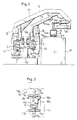
claim 1. Advantageous embodiments are described in the subclaims. - Fig. 1 is a perspective view showing the overall structure of a puller apparatus according to one embodiment of the present invention;
- Fig. 2 is a side view of the puller apparatus as seen in the direction of the arrow II in Fig. 1;
- Fig. 3 is an enlarged view showing the principal part of the apparatus shown in Fig. 2;
- Fig. 4A is a side view of a clamp head shown in Fig. 1;
- Fig. 4B is a plan view of the clamp head shown in Fig. 4A;
- Fig. 4C is a view of the clamp head as seen in the direction of the arrow IIIIC in Fig. 4A;
- Fig. 5 is an enlarged view showing the principal part of the puller system in Fig. 1;
- Fig. 6 is a side view showing the manner in which the carrier of Fig. 2 is moved to its rearmost position;
- Fig. 7 is a schematic view of an air supply system for use in the carrier shown in Fig. 1;
- Fig. 8 is a perspective view showing the principal part of the carrier shown in Fig. 1;
- Fig. 9 is a sectional view taken along the line IX-IX of Fig. 8;
- Fig. 10 is a side view showing the manner in which the carrier of Fig. 2 is moved to its foremost position;
- Fig. 11 is a side view showing the manner in which the carrier of Fig. 1 is operated; and
- Fig. 12 is a view showing the manner in which an extruded metal is pulled.
- As shown in Fig. 1, a puller apparatus for an extrusion machine includes an runout table R, a pair of guide rails G, G mounted on one side of the runout table R, and a pair of
corresponding carriers - The runout table R is elongate and located behind an extrusion machine M. An extruded metal A is fed from the extrusion machine M and received on the runout table R. The supplying base end of the extruded metal A is cut by a cutter (not shown). A piece of the extruded metal A thus cut is first dropped onto the runout table R and then, delivered to the other side of the runout table R.
- The guide rails G, G are supported on suitable bases Ga, Ga and extend in parallel to the runout table R. As shown in Fig. 2, each guide rail G includes an elongate structural element G2, and a pair of rail bodies G1, G1 attached to the structural element G2 through a pair of corresponding spacers G1a, G1a.
- The
carriers - The
carrier 10 movable on the guide rail G closer to the runout table R comprises amovable frame 11, a pair of rod-linke supports 12a, 12a, aswing base 13 pivotably mounted to the front end of thesupports clamp head 14 attached to the end ofswing base 13. As shown in Fig. 3, themovable frame 11 are movably supported by the rail bodies G1, G1 throughvertical rollers 11a andhorizontal rollers air tank 15 is placed on the movable frame 11 (Figs. 1 and 2). Theswing base 13 is vertically swingable relative to themovable frame 11 by means of anair cylinder 13a. - The
clamp head 14 is mounted through asupport rod 13b to the front ends of theswing base 13 and generally horizontally extends in a rearward direction (toward the extrusion machine M; see Fig. 1). A forward direction is shown by the arrow K in Fig. 1. A rearward direction is a direction opposite to the forward direction. As shown in Figs. 4A and 4B, theclamp head 14 includes a pair of right andleft jaws - The
jaws jaws jaws - The finger 14b is mounted to the frame 14c and pivotable about a pivot pin 14b1. An arm extends from one end of the pivot pin 14b1 and has a front end connected to an air cylinder 14b3. Contraction of the air cylinder 14b3 causes the finger 14b to pivot downwards (shown by a solid line in Fig. 4A), whereas extension of the air cylinder 14b3 causes the finger 14b to pivot upwards (shown by a broken line in Fig. 4A).
- When the
jaws jaws - The
carrier 10 mounted on the guide rail G remote from the runout table R is essentially identical in structure to the other carrier 10 (Figs. 1 and 2) except that asupport 12 is a single elongate arm extending over theother carrier 10. Aswing base 13B is mounted to the inner side of thearm 12 and is vertically swingable by means of a pair of air cylinders 13a1, 13a1. - As shown in Figs. 2 and 5, the
carriers swing base jaws swing base jaws other carrier 10 are closed. When the swing bases 13 or 13b is pivoted downwards, theclamp head 14 of thecarriers - The position of the
clamp head 14 when the swing bases 13 or 13B is pivoted downwards is defined as an operative position. The position of theclamp head 14 when the swing bases 13 or 13B is pivoted upwards is defined as a retracted position. One of the clamp heads 14 in its operative position never interferes with theother clamp head 14 in its retracted position. - The
carriers endless wires 16, 16 (Fig. 1). Eachwire 16 extends around a pair ofpulleys front pulley 16a remote from the extrusion machine M is connected to adrive source 16b such as a hydraulic motor. Ahydraulic damper 16c is located adjacent to eachpulley 16a to limit movement of thecarrier 10. As an alternative, thefront pulley 16a connected to thedrive source 16b may be in the form of a drum. - A pair of
coupler carrier 10 and connected to an air source (not shown). When thecarrier 10 reaches its rearmost position, theair coupler 15a is automatically coupled to anair coupler 15b of thecarrier 10 to replenish theair tank 15. Theair tank 15 has such a volume as to control operation at least until thecarrier 10 is returned and may include a booster to compensate a decrease in the pressure of air. - As shown in Fig. 6, the
carrier 10 has aslide rod 17 through which opposite ends of thewire 16 is connected to form an endless wire. Theslide rod 17 is slidable back and forth through a pair of bearingblocks dog block 17b is secured to theslide rod 17. Movement of theslide rod 17 is limited when thedog block 17b comes into contact with eachbearing block 17a. - Three mechanical valves V3a, V4a, V4b are located between the
bearing blocks dog block 17b is advanced. The mechanical valves V3a, V4a, V4b are disposed between theair tank 15 and theair cylinders 13a (or 13al), 14a4, 14b3 (Fig. 7). When thedog block 17b is advanced to operate the mechanical valves V3a, V4a, V4b, the swing base 13 (or 13B) is pivoted downwards to move theclamp head 14 to its operative position. Then, thejaws - As shown in Fig. 7, a check valve CV is disposed between the
air couplers air tank 15, another mechanical valve V3b is coupled in parallel to the mechanical valve V3a. And the valve V3b is rendered operative by aswing arm 18 with an associatedroller 18a which is mounted to the movable frame 11 (Fig. 6). Specifically, the mechanical valve V3b is rendered operative when theroller 18a of theswing arm 18 is engaged with acontrol rail 18b. Thecontrol rail 18b is attached to the guide rail G adjacent to the extrusion machine M or a position where the rearward movement of thecarrier 10 is limited (Figs. 3 and 6). - As shown in Fig. 8, a
control block 19 is secured to the front end of theslide rod 17. Themovable frame 11 has a pair of stopper levers 21 and 22 engageable from the upper portion with thecontrol block 19 and cooperative with a control mechanism to limit forward and rearward movements of theslide rod 17. Thestopper lever 21 has two arms 21a and 21b, a roller 21b1 is mounted to the arm 21b. Also, a roller 22a is mounted to the front end of thestopper lever 22. - The
control block 19 has a forwardly inclinedcentral surface 19a, and rearwardly inclined side surfaces 19b, 19b. The arm 21a of thestopper lever 21 and the roller 21b1 of the other arm 21b correspond with theinclined surfaces - As shown in Fig. 8, a shaft 23 extends from the
stopper lever 21. An arm 23a extends from the shaft 23. A spring 23b has one end connected to the arm 23a. Thus, thestopper lever 21 is always urged toward thecontrol block 19. A connecting rod 23c has one end connected to the front end of the arm 23a and the other end connected to one end of a swing arm 23d. Aroller 23e is mounted to the other end of the swing arm 23d. - An upstanding cylinder 24 (Figs. 6 and 8) corresponds in position to the
roller 23e when thecarrier 10 is moved to its rearmost position. Thecylinder 24 has a rod, and anengaging element 24a attached to the rod and adapted to engage with theroller 23e. When the rod is extended, the engagingelement 24a is brought into engagement with theroller 23e. This inhibits forward movement of thecarrier 10 in its rearmost position. Retraction of the rod allows the forward movement of thecarrier 10. When the cylinder is extended, thestopper lever 21 is pivoted upwards through the swing arm 23d, the connecting rod 23c, the arm 23a, and the shaft 23. This causes release of thestopper level 21 from thecontrol block 19. When thecylinder 24 is contracted, thestopper lever 21 is brought into engagement with thecontrol block 19 so as to inhibit forward movement of thecontrol block 19. - The
stopper lever 22 is pivotable with a shaft 22b and is connected to another swing lever 25 through a connecting piece 25a. Aroller 25b is mounted to the front end of the swing lever 25. - A
movable rail 26 extends substantially along the entire length of the guide rail G (Figs. 3, 6 and 8). Thenroller 25b is lifted in a suitable position of themovable rail 26. Themovable rail 26 is vertically translated by acylinder 26c through a plurality oflinks 26a. Only one of theselinks 26a is shown in Figs. 6 and 8. Extraction and contraction of thecylinder 26c cause vertical translational movement of themovable rail 26. This results in corresponding pivotal movement of thestopper lever 22 to allow and inhibit rearward movement of thecontrol block 19. - Either one of the
carriers 10 is moved to a position most close to the extrusion machine, and theother carrier 10 rests in a position corresponding to the length of a metal A to be produced. - When the
carrier 10 is moved to its rearward position by thedrive source 16b through thewire 16, theslide rod 17 is in its rearmost position as a result of contact between thedog block 17b and therear bearing block 17a as shown in Fig. 6. At this time, theroller 18a of theswing arm 18 is placed on thecontrol rail 18b to operate the mechanical valve V3b. On the other hand, the mechanical valves V3a, V4a, V4b are rendered inoperative. - When the mechanical valve V3b is operated, the swing base 13 (or 13B) is pivoted downwards. The
jaws clamp head 14, although in its operative position, does not clamp the extruded metal. Also, thecylinder 24 is contracted to pivot thestopper lever 21 downwards so as to inhibit forward movement of thecontrol block 19 in its rearmost position. Thecylinder 26c is contracted to lower themovable rail 26. Theair coupler 15b of thecarrier 10 in its rearmost position is automatically coupled to theair coupler 15a. A sufficient amount of air is then supplied to theair tank 15. - In the other carrier in a suitable forward position as shown in Fig. 10, the
slide rod 17 is in its rearmost position since the extruded metal A is unclamped. The mechanical valves V3b, V4a, V4b are all rendered inoperative. Thus, the swing arm 13 (or 13B) is pivoted upwards, and theclamp head 14 is in its retracted position. Thejaws cylinder 26c is temporarily extended to lift themovable rail 26 and thus, thestopper lever 22. Thecylinder 26c may immediately thereafter be contracted. - As shown in Fig. 11, the
cylinder 24 is extended to provide an engagement between theengaging element 24a and theroller 23e so as to inhibit forward movement of thecarrier 10. Thestopper lever 21 is pivoted upwards to allow forward movement of thecontrol block 19. Thedrive source 16b is then operable to apply a light tractional force to thewire 16. This causes only theslide rod 17 to move in a forward direction, and the carrier is not moved. As a result, the mechanical valves V3a, V4a, V4b are rendered operative in this order. Thejaws clamp head 14 to clamp the front end of the metal A as fed from the extrusion machine M. - At this time, the
control block 19 is moved, through itsinclined surface 19a, beyond thestopper lever 22. This prevents rearward movement of the control block 19 (Fig. 11). As the mechanical valve V3b is rendered operative by thecontrol rail 18b, the swing base 13 (or 13B) is pivoted downwards to move theclamp head 14 to its operative position. - Next, the
cylinder 24 is contracted to allow forward movement of thecarrier 10. A predetermined amount of tractional force is applied from thedrive source 16b to thewire 16. When the extrusion machine M is operated, thecarrier 10 is advanced at an extrusion speed of the metal A. During an extrusion process, the metal A is pulled constantly by a force identical in amount to such a predetermined tractional force exerted on the wire 16 (Fig. 12(2)). When thecarrier 10 is advanced, theair coupler 15b is automatically separated from theair coupler 15a. Air pressure supplied from theair tank 15 so as to control the operation of the elements on thecarrier 10. - When the
carrier 10 is moved beyond the entire length of thecontrol rail 18b, theswing arm 18 is returned to render the mechanical valve V3b inoperative. However, the mechanical valve V3a is already operative to keep theclamp head 14 in its operative position. - When one of the
carriers 10 initiates traction of the extruded metal A, thedrive source 16b is operated to move theother carrier 10 toward the extrusion machine M through thecorresponding wire 16. Although thecarriers corresponding control rails 18b, they do not interface with one another. This is because theclamp head 14 of thecarrier 10 which is operated to pull the extruded metal is in its operated position, whereas theclamp head 14 of theother carrier 10 is in its retracted position. - When a predetermined length of the extruded metal A is pulled, the extrusion machine M is temporarily stopped. The base end of the extruded metal A is then cut by a cutter not shown. The
carrier 10 which is operating to pull the extruded metal is automatically stopped when the extrusion machine M is stopped. After the extruded metal A has been cut, thecarrier 10 is advanced at a constant speed by a predetermined distance L (Fig. 12(3)). This further pulls the extruded metal A. - In the meantime, the
other carrier 10 reaches the area of thecontrol rail 18b. The mechanical valve V3b is thus operative to force theclamp head 14 to its operative position while thecarrier 10 is being retreated. In this case, the extruded metal A as pulled does not interfere since thejaws carrier 10 is automatically stopped when it is moved to its rearmost position. Theair couplers air tank 15 with air. - The drive source is deenergized to stop the
carrier 10 which has pulled the extruded metal A by the distance L. Theair cylinder 26c is thereafter extended to lift the movable rail 26 (Fig. 10. This causes thestopper lever 22 to pivot upwards to allow rearward movement of thecontrol block 19. Thedrive source 16b is then move thewire 16 in a rearward direction. This causes theslide rod 17 to move in a rearward direction. The mechanical valves V4b, V4a, V3a are then returned to its inoperative condition in this order. As a result, the finger 14b is pivoted upwards to cause theclamp head 14 to unclamp the extruded metal A. Lateral opening of the fingers results in dropping of the front end of the extruded metal A on the runout table R. Theswing base 13 is pivoted upwards to move theclamp head 14 to its retracted position. Thecarrier 10 is returned to its rest position. - When the
slide rod 17 is retreated, thecontrol block 19 is moved behind thestopper lever 21 through itsinclined surfaces control block 19. As themovable rail 26 extends substantially along the entire length of the guide rail G, the extruded metal A can be unclamped without fail by means of theair cylinder 26c even if the position in which thecarrier 10 is stopped is changed in response to the length of the metal A. As such, required forward movement of thecarrier 10 can be minimized. - Next, the
other carrier 10 in its rearmost position is similarly operated to pull the extruded metal A. Thereafter, the twocarriers - The extruded metal A as pulled by the
carrier 10 and dropped on the runout table R is laterally moved by a transfer mechanism (not shown) in a direction opposite to the guide rails G, G. When thecarrier 10 is advanced, the speed of the carriers is limited by the speed at which the metal A is extruded. On the other hand, when thecarrier 10 is retreated to pull the next metal A, thecarrier 10 can be moved at any speeds by means of thedrive source 16b and thewire 16. - With the present invention thus far described, a pair of carriers are movable on a corresponding pair of guide rails mounted on one side of the runout table. When the carrier is advanced, the clamp head is in its operative position. When the carrier is retreated, the calmp head is in its retracted position so as not to interface with the other clamp head in its operative position. Each carrier is moved back and forth on each single guide rail. This enables provision of a simple drive system. Since no subrails are employed, the movement of the carriers can be minimized in accordance with the length of a metal to be pulled. Advantageously, a full open space is avaiable above the runout table to accommodate a cooling fan since no guide rail is placed above the runout talbe.
Claims (6)
- A puller apparatus for an extrusion machine wherein an extruded metal (A) fed from the extrusion machine (M) is pulled on a runout table (R), comprising- a pair of guide rails (G) mounted on one side of said runout table (R) and extending in parallel thereto:- carriers (10) being movable on said guide rails (G) and- clamp heads (14) for clamping said extruded metal (A) to be pulled on said runout table (R) each being mounted to each carrier (10) through a support (12a; 12);characterized in that- each carrier (10) is movable on one and the same guide rail (G);- each clamp head (14) is mounted to the corresponding carrier (10) through a swing base (13; 13B) and is movable between an operative and a retracted position and- said carriers (10) are such constructed that one of them with its clamp head (14) in its operative position and the other with its clamp head (14) in its retracted position do not interfere with one another when they are moved back and forth.
- A puller apparatus for an extrusion machine according to claim 1, wherein each carrier (10) includes an air tank (15), and cylinders (13a, 13a1 ; 14a4; 14b3) connected to said air tank through mechanical valves (V3a, V4a, V4b) so as to actuate said swing base (13; 13B) and said clamp head (14), and wherein each of said air tanks (15) is connected to an air coupler (15b) to replenish said air tank.
- A puller apparatus for an extrusion machine according to claim 2, wherein each of said carriers (10) has a slidable slide rod (17) with an associated dog block (17b), said slide rod having opposite ends connected to ends of a carrier drive wire (16), and wherein said mechanical valves (V3a, V4a, V4b) are controllably mounted on a pass of travel of said dog block(17b).
- A puller apparatus for an extrusion machine according to claim 3, wherein said slide rod (17) includes a control block (19), and wherein stopper levers (21, 22) are movable to and from said control block so as to limit forward and rearward movements of said control block.
- A puller apparatus for an extrusion machine according to claim 2, wherein each of said carriers (10) includes a mechanical valve(V3b) opened and closed in response to pivotal motion of an arm (18) and an associated roller (18a), and wherein said mechanical valve (V3b) is arranged in parallel with said mechanical valve (V3a) and disposed between said air tank and said cylinder (13a; 13a1).
- A puller apparatus for an extrusion machine according to claim 1, wherein one of said carriers (10) includes support (12) having an elongate arm extending over the other carrier, said clamp head (14) being attached to said swing base (13b), and said swing base (13b) being pivotably mounted to the front end of said support (12), and wherein the other carrier (10) includes rod-like supports (12a) said clamp head (14) being attached to said swing base (13), and said swing base (13) being pivotably mounted to ends of said supports (12a).
Applications Claiming Priority (2)
| Application Number | Priority Date | Filing Date | Title |
|---|---|---|---|
| JP214600/90 | 1990-08-13 | ||
| JP2214600A JPH0798215B2 (en) | 1990-08-13 | 1990-08-13 | Extruder puller device |
Publications (2)
| Publication Number | Publication Date |
|---|---|
| EP0471339A1 EP0471339A1 (en) | 1992-02-19 |
| EP0471339B1 true EP0471339B1 (en) | 1994-11-30 |
Family
ID=16658399
Family Applications (1)
| Application Number | Title | Priority Date | Filing Date |
|---|---|---|---|
| EP91113576A Expired - Lifetime EP0471339B1 (en) | 1990-08-13 | 1991-08-13 | Puller apparatus for an extrusion machine |
Country Status (4)
| Country | Link |
|---|---|
| US (1) | US5201209A (en) |
| EP (1) | EP0471339B1 (en) |
| JP (1) | JPH0798215B2 (en) |
| DE (1) | DE69105405T2 (en) |
Families Citing this family (11)
| Publication number | Priority date | Publication date | Assignee | Title |
|---|---|---|---|---|
| AT403258B (en) * | 1993-10-04 | 1997-12-29 | Reisch Ing Walter | EXTRACTION DEVICE ON EXTRACTION PRESSES |
| RU2159686C2 (en) * | 1998-12-22 | 2000-11-27 | Открытое акционерное общество "Уральский завод тяжелого машиностроения" | Drawing out apparatus |
| CN101722207B (en) * | 2009-12-28 | 2011-12-07 | 中国重型机械研究院有限公司 | Large hauling machine liner motor drive method |
| CN101850377B (en) * | 2009-12-30 | 2012-05-30 | 中国重型机械研究院有限公司 | Alternating double traction device structure |
| CN102451895A (en) * | 2010-10-20 | 2012-05-16 | 吴江市新申铝业科技发展有限公司 | Section bar traction device |
| JP2012176440A (en) * | 2012-05-01 | 2012-09-13 | Giken Kk | Device for collecting cutting chips |
| JP6144135B2 (en) * | 2013-07-17 | 2017-06-07 | Ykk株式会社 | Towing device for profiles |
| CN103691759B (en) * | 2013-12-09 | 2015-09-09 | 台澳铝业(台山)有限公司 | Aluminum profile tractor |
| JP6653587B2 (en) * | 2016-02-04 | 2020-02-26 | アイシン軽金属株式会社 | Extrusion equipment |
| IT201700115517A1 (en) * | 2017-10-13 | 2019-04-13 | Danieli Off Mecc | PULLERS SYSTEM WITH SINGLE-WAY GUIDES |
| CN119910049B (en) * | 2025-04-02 | 2025-07-04 | 宁波蒙恩铝业有限公司 | Aluminum profile extrusion traction device |
Family Cites Families (13)
| Publication number | Priority date | Publication date | Assignee | Title |
|---|---|---|---|---|
| AT212213B (en) * | 1958-05-31 | 1960-12-12 | Beteiligungs & Patentverw Gmbh | Conveying device for the conveyance of constantly moving material to be conveyed and a method for conveying with such a device |
| DE1299589B (en) * | 1961-06-13 | 1969-07-24 | Sack Gmbh Maschf | Device for drawing out and dividing a strand emerging from a die of an extrusion press |
| FR1306692A (en) * | 1961-09-05 | 1962-10-19 | Alcan Aluminium De France | Extrusion press serving carousel |
| US3668910A (en) * | 1970-10-06 | 1972-06-13 | Granco Equipment | Extrusion handling apparatus |
| JPS557284Y2 (en) * | 1977-03-04 | 1980-02-19 | ||
| DE2828259C2 (en) * | 1978-06-28 | 1987-04-09 | Degussa Ag, 6000 Frankfurt | Process for the preparation of methyl isocyanate |
| JPS5922883Y2 (en) * | 1980-08-14 | 1984-07-09 | ワイケイケイ株式会社 | Plastic for extruder |
| DE3040236A1 (en) * | 1980-10-24 | 1982-05-13 | Friedrich Wilhelm Dipl.-Ing. 5600 Wuppertal Elhaus | Extraction machine for extruded profiles - has second extraction unit independent of first, with one guide carriage and drawing head |
| JPS5922883A (en) * | 1982-07-23 | 1984-02-06 | 住友重機械工業株式会社 | Compensator for positional displacement of hung load |
| JPS5922883U (en) * | 1982-08-04 | 1984-02-13 | 新日軽株式会社 | Double sash with article storage area |
| JPS6246110U (en) * | 1985-09-10 | 1987-03-20 | ||
| IT1214185B (en) * | 1987-05-22 | 1990-01-10 | Danieli Off Mecc | EXTRUDED TOWING DEVICE FOR EXTRUSION PRESS. |
| DE3917002C1 (en) * | 1989-05-24 | 1990-05-10 | Elhaus Industrieanlagen Gmbh, 7703 Rielasingen-Worblingen, De |
-
1990
- 1990-08-13 JP JP2214600A patent/JPH0798215B2/en not_active Expired - Fee Related
-
1991
- 1991-08-12 US US07/743,868 patent/US5201209A/en not_active Expired - Fee Related
- 1991-08-13 DE DE69105405T patent/DE69105405T2/en not_active Expired - Fee Related
- 1991-08-13 EP EP91113576A patent/EP0471339B1/en not_active Expired - Lifetime
Also Published As
| Publication number | Publication date |
|---|---|
| EP0471339A1 (en) | 1992-02-19 |
| JPH0798215B2 (en) | 1995-10-25 |
| US5201209A (en) | 1993-04-13 |
| DE69105405D1 (en) | 1995-01-12 |
| JPH04182022A (en) | 1992-06-29 |
| DE69105405T2 (en) | 1995-04-20 |
Similar Documents
| Publication | Publication Date | Title |
|---|---|---|
| US5201209A (en) | Puller apparatus for an extrusion machine | |
| US4895507A (en) | Die assembly exchanging apparatus for extruder | |
| US5000395A (en) | Apparatus for inserting a winding sleeve or core into a winding machine | |
| US4919028A (en) | Shearing machine | |
| US4506573A (en) | Shearing machine | |
| CN101044007B (en) | Plants for the production of bellows | |
| CN109066249B (en) | USB wire automatic molding machine | |
| US3964142A (en) | Apparatus for cutting and stripping insulated wire | |
| US5794481A (en) | Device for bending or curving hollow-section strips | |
| US3657832A (en) | Method of and apparatus for feeding laundered textile sheets to a feed band | |
| US4037731A (en) | Workpiece transport apparatus | |
| SE504297C2 (en) | Method and apparatus for loosening cathode plates | |
| ITMI991167A1 (en) | BAR FEEDER FOR MACHINE TOOLS WITH MAIN PUSHING ORGAN AND LOADING DEVICE FOR MOBILE BARS VERTICALLY IN | |
| DK168961B1 (en) | Apparatus for supplying flat laundry items to further processing machines, especially an ironing machine | |
| EP0291734A1 (en) | Device to draw extruded stock for an extrusion press | |
| CN217555133U (en) | Automatic aluminum bar loading and unloading device | |
| JP2665700B2 (en) | Method and apparatus for pulling extruded material | |
| CN109130072B (en) | USB wire automatic molding machine | |
| CN114918335A (en) | A claw mechanism of a tube shrinking machine | |
| JPH0378990A (en) | Position setter for connector of molding machine | |
| CN220971777U (en) | Molybdenum wire end automatic sander | |
| CN112475147A (en) | Traction type silk cutting equipment | |
| CN220295516U (en) | Oil pressure wire drawing machine | |
| US4578972A (en) | Apparatus for drawing wire | |
| US2702766A (en) | Method and apparatus for processing strip material through treating units |
Legal Events
| Date | Code | Title | Description |
|---|---|---|---|
| PUAI | Public reference made under article 153(3) epc to a published international application that has entered the european phase |
Free format text: ORIGINAL CODE: 0009012 |
|
| AK | Designated contracting states |
Kind code of ref document: A1 Designated state(s): CH DE FR GB IT LI |
|
| 17P | Request for examination filed |
Effective date: 19920416 |
|
| 17Q | First examination report despatched |
Effective date: 19930728 |
|
| GRAA | (expected) grant |
Free format text: ORIGINAL CODE: 0009210 |
|
| AK | Designated contracting states |
Kind code of ref document: B1 Designated state(s): CH DE FR GB IT LI |
|
| REF | Corresponds to: |
Ref document number: 69105405 Country of ref document: DE Date of ref document: 19950112 |
|
| ITF | It: translation for a ep patent filed | ||
| ET | Fr: translation filed | ||
| PLBE | No opposition filed within time limit |
Free format text: ORIGINAL CODE: 0009261 |
|
| STAA | Information on the status of an ep patent application or granted ep patent |
Free format text: STATUS: NO OPPOSITION FILED WITHIN TIME LIMIT |
|
| 26N | No opposition filed | ||
| REG | Reference to a national code |
Ref country code: GB Ref legal event code: IF02 |
|
| PGFP | Annual fee paid to national office [announced via postgrant information from national office to epo] |
Ref country code: FR Payment date: 20020805 Year of fee payment: 12 |
|
| PGFP | Annual fee paid to national office [announced via postgrant information from national office to epo] |
Ref country code: GB Payment date: 20020806 Year of fee payment: 12 |
|
| PGFP | Annual fee paid to national office [announced via postgrant information from national office to epo] |
Ref country code: CH Payment date: 20020807 Year of fee payment: 12 |
|
| PGFP | Annual fee paid to national office [announced via postgrant information from national office to epo] |
Ref country code: DE Payment date: 20020827 Year of fee payment: 12 |
|
| PG25 | Lapsed in a contracting state [announced via postgrant information from national office to epo] |
Ref country code: GB Free format text: LAPSE BECAUSE OF NON-PAYMENT OF DUE FEES Effective date: 20030813 |
|
| PG25 | Lapsed in a contracting state [announced via postgrant information from national office to epo] |
Ref country code: LI Free format text: LAPSE BECAUSE OF NON-PAYMENT OF DUE FEES Effective date: 20030831 Ref country code: CH Free format text: LAPSE BECAUSE OF NON-PAYMENT OF DUE FEES Effective date: 20030831 |
|
| PG25 | Lapsed in a contracting state [announced via postgrant information from national office to epo] |
Ref country code: DE Free format text: LAPSE BECAUSE OF NON-PAYMENT OF DUE FEES Effective date: 20040302 |
|
| GBPC | Gb: european patent ceased through non-payment of renewal fee |
Effective date: 20030813 |
|
| REG | Reference to a national code |
Ref country code: CH Ref legal event code: PL |
|
| PG25 | Lapsed in a contracting state [announced via postgrant information from national office to epo] |
Ref country code: FR Free format text: LAPSE BECAUSE OF NON-PAYMENT OF DUE FEES Effective date: 20040430 |
|
| REG | Reference to a national code |
Ref country code: FR Ref legal event code: ST |
|
| PG25 | Lapsed in a contracting state [announced via postgrant information from national office to epo] |
Ref country code: IT Free format text: LAPSE BECAUSE OF NON-PAYMENT OF DUE FEES;WARNING: LAPSES OF ITALIAN PATENTS WITH EFFECTIVE DATE BEFORE 2007 MAY HAVE OCCURRED AT ANY TIME BEFORE 2007. THE CORRECT EFFECTIVE DATE MAY BE DIFFERENT FROM THE ONE RECORDED. Effective date: 20050813 |