EP0469956A1 - Plane motion mechanism - Google Patents
Plane motion mechanism Download PDFInfo
- Publication number
- EP0469956A1 EP0469956A1 EP91402027A EP91402027A EP0469956A1 EP 0469956 A1 EP0469956 A1 EP 0469956A1 EP 91402027 A EP91402027 A EP 91402027A EP 91402027 A EP91402027 A EP 91402027A EP 0469956 A1 EP0469956 A1 EP 0469956A1
- Authority
- EP
- European Patent Office
- Prior art keywords
- motion mechanism
- plane motion
- belts
- mechanism according
- power transmitting
- Prior art date
- Legal status (The legal status is an assumption and is not a legal conclusion. Google has not performed a legal analysis and makes no representation as to the accuracy of the status listed.)
- Granted
Links
Images







Classifications
-
- F—MECHANICAL ENGINEERING; LIGHTING; HEATING; WEAPONS; BLASTING
- F16—ENGINEERING ELEMENTS AND UNITS; GENERAL MEASURES FOR PRODUCING AND MAINTAINING EFFECTIVE FUNCTIONING OF MACHINES OR INSTALLATIONS; THERMAL INSULATION IN GENERAL
- F16H—GEARING
- F16H19/00—Gearings comprising essentially only toothed gears or friction members and not capable of conveying indefinitely-continuing rotary motion
- F16H19/02—Gearings comprising essentially only toothed gears or friction members and not capable of conveying indefinitely-continuing rotary motion for interconverting rotary or oscillating motion and reciprocating motion
- F16H19/06—Gearings comprising essentially only toothed gears or friction members and not capable of conveying indefinitely-continuing rotary motion for interconverting rotary or oscillating motion and reciprocating motion comprising flexible members, e.g. an endless flexible member
-
- B—PERFORMING OPERATIONS; TRANSPORTING
- B23—MACHINE TOOLS; METAL-WORKING NOT OTHERWISE PROVIDED FOR
- B23Q—DETAILS, COMPONENTS, OR ACCESSORIES FOR MACHINE TOOLS, e.g. ARRANGEMENTS FOR COPYING OR CONTROLLING; MACHINE TOOLS IN GENERAL CHARACTERISED BY THE CONSTRUCTION OF PARTICULAR DETAILS OR COMPONENTS; COMBINATIONS OR ASSOCIATIONS OF METAL-WORKING MACHINES, NOT DIRECTED TO A PARTICULAR RESULT
- B23Q1/00—Members which are comprised in the general build-up of a form of machine, particularly relatively large fixed members
- B23Q1/25—Movable or adjustable work or tool supports
- B23Q1/26—Movable or adjustable work or tool supports characterised by constructional features relating to the co-operation of relatively movable members; Means for preventing relative movement of such members
- B23Q1/34—Relative movement obtained by use of deformable elements, e.g. piezoelectric, magnetostrictive, elastic or thermally-dilatable elements
-
- B—PERFORMING OPERATIONS; TRANSPORTING
- B23—MACHINE TOOLS; METAL-WORKING NOT OTHERWISE PROVIDED FOR
- B23Q—DETAILS, COMPONENTS, OR ACCESSORIES FOR MACHINE TOOLS, e.g. ARRANGEMENTS FOR COPYING OR CONTROLLING; MACHINE TOOLS IN GENERAL CHARACTERISED BY THE CONSTRUCTION OF PARTICULAR DETAILS OR COMPONENTS; COMBINATIONS OR ASSOCIATIONS OF METAL-WORKING MACHINES, NOT DIRECTED TO A PARTICULAR RESULT
- B23Q1/00—Members which are comprised in the general build-up of a form of machine, particularly relatively large fixed members
- B23Q1/25—Movable or adjustable work or tool supports
- B23Q1/44—Movable or adjustable work or tool supports using particular mechanisms
- B23Q1/48—Movable or adjustable work or tool supports using particular mechanisms with sliding pairs and rotating pairs
-
- B—PERFORMING OPERATIONS; TRANSPORTING
- B23—MACHINE TOOLS; METAL-WORKING NOT OTHERWISE PROVIDED FOR
- B23Q—DETAILS, COMPONENTS, OR ACCESSORIES FOR MACHINE TOOLS, e.g. ARRANGEMENTS FOR COPYING OR CONTROLLING; MACHINE TOOLS IN GENERAL CHARACTERISED BY THE CONSTRUCTION OF PARTICULAR DETAILS OR COMPONENTS; COMBINATIONS OR ASSOCIATIONS OF METAL-WORKING MACHINES, NOT DIRECTED TO A PARTICULAR RESULT
- B23Q1/00—Members which are comprised in the general build-up of a form of machine, particularly relatively large fixed members
- B23Q1/25—Movable or adjustable work or tool supports
- B23Q1/44—Movable or adjustable work or tool supports using particular mechanisms
- B23Q1/48—Movable or adjustable work or tool supports using particular mechanisms with sliding pairs and rotating pairs
- B23Q1/4804—Movable or adjustable work or tool supports using particular mechanisms with sliding pairs and rotating pairs a single rotating pair followed perpendicularly by a single sliding pair
- B23Q1/4809—Movable or adjustable work or tool supports using particular mechanisms with sliding pairs and rotating pairs a single rotating pair followed perpendicularly by a single sliding pair followed perpendicularly by a single rotating pair
-
- B—PERFORMING OPERATIONS; TRANSPORTING
- B25—HAND TOOLS; PORTABLE POWER-DRIVEN TOOLS; MANIPULATORS
- B25J—MANIPULATORS; CHAMBERS PROVIDED WITH MANIPULATION DEVICES
- B25J9/00—Program-controlled manipulators
- B25J9/003—Program-controlled manipulators having parallel kinematics
- B25J9/0078—Program-controlled manipulators having parallel kinematics actuated by cables
-
- G—PHYSICS
- G05—CONTROLLING; REGULATING
- G05D—SYSTEMS FOR CONTROLLING OR REGULATING NON-ELECTRIC VARIABLES
- G05D3/00—Control of position or direction
-
- F—MECHANICAL ENGINEERING; LIGHTING; HEATING; WEAPONS; BLASTING
- F16—ENGINEERING ELEMENTS AND UNITS; GENERAL MEASURES FOR PRODUCING AND MAINTAINING EFFECTIVE FUNCTIONING OF MACHINES OR INSTALLATIONS; THERMAL INSULATION IN GENERAL
- F16H—GEARING
- F16H19/00—Gearings comprising essentially only toothed gears or friction members and not capable of conveying indefinitely-continuing rotary motion
- F16H19/02—Gearings comprising essentially only toothed gears or friction members and not capable of conveying indefinitely-continuing rotary motion for interconverting rotary or oscillating motion and reciprocating motion
- F16H19/06—Gearings comprising essentially only toothed gears or friction members and not capable of conveying indefinitely-continuing rotary motion for interconverting rotary or oscillating motion and reciprocating motion comprising flexible members, e.g. an endless flexible member
- F16H2019/069—Gearings comprising essentially only toothed gears or friction members and not capable of conveying indefinitely-continuing rotary motion for interconverting rotary or oscillating motion and reciprocating motion comprising flexible members, e.g. an endless flexible member with means for generating two superposed movements, e.g. for driving a X-Y table
-
- Y—GENERAL TAGGING OF NEW TECHNOLOGICAL DEVELOPMENTS; GENERAL TAGGING OF CROSS-SECTIONAL TECHNOLOGIES SPANNING OVER SEVERAL SECTIONS OF THE IPC; TECHNICAL SUBJECTS COVERED BY FORMER USPC CROSS-REFERENCE ART COLLECTIONS [XRACs] AND DIGESTS
- Y10—TECHNICAL SUBJECTS COVERED BY FORMER USPC
- Y10T—TECHNICAL SUBJECTS COVERED BY FORMER US CLASSIFICATION
- Y10T74/00—Machine element or mechanism
- Y10T74/18—Mechanical movements
- Y10T74/18568—Reciprocating or oscillating to or from alternating rotary
- Y10T74/18832—Reciprocating or oscillating to or from alternating rotary including flexible drive connector [e.g., belt, chain, strand, etc.]
- Y10T74/18848—Reciprocating or oscillating to or from alternating rotary including flexible drive connector [e.g., belt, chain, strand, etc.] with pulley
-
- Y—GENERAL TAGGING OF NEW TECHNOLOGICAL DEVELOPMENTS; GENERAL TAGGING OF CROSS-SECTIONAL TECHNOLOGIES SPANNING OVER SEVERAL SECTIONS OF THE IPC; TECHNICAL SUBJECTS COVERED BY FORMER USPC CROSS-REFERENCE ART COLLECTIONS [XRACs] AND DIGESTS
- Y10—TECHNICAL SUBJECTS COVERED BY FORMER USPC
- Y10T—TECHNICAL SUBJECTS COVERED BY FORMER US CLASSIFICATION
- Y10T74/00—Machine element or mechanism
- Y10T74/20—Control lever and linkage systems
- Y10T74/20207—Multiple controlling elements for single controlled element
- Y10T74/20341—Power elements as controlling elements
- Y10T74/20348—Planar surface with orthogonal movement and rotation
Definitions
- This invention relates to an automatization apparatus for machining processing, assembling, measuring, inspection and the like and, more particularly, to a plane motion mechanism suitable for determining a position and a posture of a table in a plane.
- a motion in a plane has three degrees of freedom.
- the motion is realized by the use of three joints.
- positioning of a workpiece on a machining center is practiced such that a slide table in a Y-direction is mounted on a slide table in an X-direction, and a rotary table in a ⁇ -direction is mounted on an assembly including the slide tables in the X- and Y-directions, to control three axes including X, Y and ⁇ .
- This is called an orthogonal coordinate system.
- an upper arm is moved angularly by a shoulder joint through ⁇ 1.
- a front arm is moved angularly by an elbow joint through ⁇ 2, and a hand is rotated by a wrist joint through ⁇ 3, to control three axes including ⁇ 1, ⁇ 2 and ⁇ 3, thereby obtaining a position and a posture (X, Y, ⁇ ).
- X l1cos ⁇ 1 + l2cos( ⁇ 1 + ⁇ 2)
- Y l1sin ⁇ 1 + l2sin( ⁇ 1 + ⁇ 2)
- ⁇ ⁇ 1 + ⁇ 2 + ⁇ 3
- the arrangement is such that a second axis is mounted on a motion of a first axis, and the last axis is mounted on an assemble including the first and second axes.
- the axis in the lowermost level must move drive mechanisms and guide mechanisms for the respective upper two level including the second and third axes.
- a large power is required.
- a plane motion mechanism comprising: a base having a top planar surface; a table mounted on the top planar surface of the base for movement thereon in plane motion, the table having an outer peripheral side surface; at least first, second and third, elongated power transmitting means having respective one and other ends, one end portions of the respective first, second and third power transmitting means adjacent respectively to the one ends thereof being wound about the outer peripheral side surface of the table; at least first and second drive means to which the other ends of the respective first and second power transmitting means are connected respectively, for applying tension forces respectively to the first and second power transmitting means; and tension-applying means to which the other end of the third power transmitting means is connected, for applying a tension force to the third power transmitting means.
- a plane motion mechanism includes four cylindrical elements having respective cylindrical outer peripheral side surfaces, the cylindrical elements being fixedly mounted on the base respectively at the four corners of the imaginary rectangle on the top planar surface of the base, four belts passing respectively about the cylindrical outer peripheral side surfaces of the respective cylindrical elements so that the four belts are defined in their respective tensile directions.
- the table when the other end of each of the belts having one end thereof wound about the table is taken up, the table is moved angularly in a direction in which the belt is pulled, or is moved linearly. If the tensile directions of the belts are defined, since the drive means and the table are connected to each other, the table is moved angularly in a predetermined direction or is moved linearly.
- the amount of movement can be controlled by a winding amount of the belts due to the drive means.
- the table is circular in planar cross-section, and the radius of the table is b .
- the cylindrical elements are mounted respectively at corners of the imaginary rectangle so as to extend vertically.
- the lengths of the respective belts to the cylindrical elements can be obtained by the following equations:
- first, second, third and fourth drive means are drive motors for pulling the four belts, respectively, and the plane motion mechanism further includes a control unit for controlling the first, second, third and fourth drive motors.
- one end of the belt is wound about the table and is fixedly connected thereto.
- the belts extending through the opposed corners on the base can be wound about the table. In the latter case, it is a necessary condition that the belts cannot slide along the grooves in the table.
- the grooves in the table are brought to helical configuration, the thickness of the mechanism increases for necessary rotational speed.
- a plane motion mechanism comprising: a base having a top planar surface; a table counted on the top planar surface of the base for movement thereon in plane motion, the table being circular in cross-section and having an outer peripheral side surface: at least a pair of first and second elongated power transmitting means extending in contact with the outer peripheral side surface of the table to generate friction between the first and second power transmitting means and the outer peripheral side surface of the table; and a pair of drive means for driving the first and second power transmitting means, respectively.
- the use of the endless belts enables rotational speed of the table not to be limited. Accordingly, it is possible to control the table more freely. Further, since the table can be controlled in position regardless of the number of turns of the belts, it is possible to realize a plane motion with a accuracy , by means of more simple arrangement.
- FIG. 1 there is shown a plane motion mechanism according to a first embodiment of the invention.
- the plane motion mechanism comprise a base 10 having a top planar surface 91.
- the base 10 is mounted at a predetermined position in the vertical direction.
- a table 20 having a circular outer peripheral side surface 92 is mounted on the top planar surface 91 of the base 10 for linear movement and angular movement about an axis 25 thereon in plane motion.
- Four cylindrical elements 11, 12, 13 and 14 rotatable about their respective axes 93, 94, 95 and 96 have respective cylindrical outer peripheral side surfaces.
- the axes 93, 94, 95 and 96 of the respective cylindrical elements 11, 12, 13 and 14 are fixedly mounted on the top planar surface 91 of the base 10 respectively the four corners of an imaginary rectangle on the top planar surface 91 of the base 10.
- First, second, third and four elongated power transmitting means that is, four belts 1, 2, 3 and 4 pass respectively about the cylindrical outer peripheral side surfaces of the respective cylindrical elements 11, 12, 13 and 14 so that the four belts 1, 2, 3 and 4 are defined or determined in their respective tensile directions.
- the first ends of the respective belts 1,2,3 and 4 are connected respectively to four tension-applying means or drive motors 21, 22, 23 and 24, for applying tension forces respectively to the belts 1, 2, 3 and 4, i.e., for pulling the belts, respectively.
- a control unit 30 is provided for controlling the drive motors 21, 22, 23 and 24.
- the drive motors 21, 22, 23 and 24 are mounted on a side surface of the base 10 so as to extend vertically.
- the drive motors 21, 22, 23 and 24 are so-called DD motors, having no reduction gears, which can generate high torque.
- the drive motors 21, 22, 23 and 24 have respective output shafts 31, 32, 33 and 34 to which the first ends of the respective belts 1, 2, 3 and 4 are fixedly connected.
- the belts 1, 2, 3 and 4 extend respectively about the cylindrical elements 11, 12, 13 and 14, and the second ends of the respective belts 1, 2 3 and 4 are fixedly connected to the outer peripheral side surface 92 of the table 20 at their respective predetermined locations. In this connection, if the belts 1, 2, 3 and 4 vary in vertical position, the belts will be intertwined with each other.
- the table outer peripheral side surface of the table 20 is formed with a pluraltiy of belt grooves 61, 62, 63 and 64.
- each of the cylindrical elements 11, 12, 13 and 14 is formed, in its outer periphery, with a plurality of belt grooves 71, 72, 73 and 74.
- Each of the belts 1, 2, 3 and 4 extends along a corresponding one of the belt grooves 71, 72, 73 and 74 in the outer periphery of the cylindrical element 11, 12, 13 or 14.
- the output shafts 31, 32, 33 and 34 are not required to be formed therein with grooves.
- relief means is provided for relieving friction between the top planar surface 91 of the base 10 and the lower surface of the table 20.
- the relief means is made of a polytetrafluoroethylene film 81 (trade name: Teflon) or the like which is mounted on the lower surface of the table 20. Further, the lower surface of the polytetrafluoroethylene film 81 is formed with a plurality of grooves 82 for retaining a film of lubricant.
- the belts 1, 2, 3 and 4 are fixedly connected to the table 20 along their respective belt grooves 71, 72, 73 and 74 in the cylindrical elements 11, 12, 13 and 14 which are predetermined correspondingly to the belts 1, 2, 3 and 4, respectively.
- the belt 1 is fixedly connected to the outer peripheral side surface 92 of the table 20 at a point 38 remotest from the cylindrical element 11 which is mounted on the top planar surface 91 of the base 10 at at the right upper corner of the base and passes on the uppermost groove 71 in t he cylindrical element 11.
- each of the cylindrical elements 11, 12, 13 and 14, which is formed therein with the grooves 71, 72, 73 and 74, is rotatable about its axis 93, 94, 95 or 96.
- the belt 2 reaches the belt groove 62 in the outer peripheral side surface 92 of the table 20 via the second belt groove 72 in the outer peripheral side surface of the cylindrical element 12.
- the belt 2 passes about the belt groove 62 through one turn or revolution and, subsequently, is fixedly connected to the table 20 at a fixing point 39.
- the same is applicable to the belts 3 and 4, and their respective fixing points are located on a side opposite to the fixing points 38 and 39.
- the drive motors 21 and 24 take up the belts 1 and 4, respectively, while the other drive motors 22 and 23 loosen the belts 2 and 3, respectively. Further, in order to angularly move the table 20 in the clockwise direction, the belts 2 and 4 are taken up respectively about the output shafts 31 and 34 of the respective drove motors 21 and 24, while the belts 1 and 3 are loosened.
- the relationship between the motion of the table 20 and the belts 1, 2, 3 and 4 is indicated by the following table. The case where the belts 1, 2, 3 and 4 are taken up is indicated by (+), while the case where the belts 1, 2, 3 and 4 are loosened is indicated by (-).
- the amount of movement of the table 20 is determined depending upon the lenghts of the respective belts 1, 2, 3 and 4.
- the lengths of the respective belts 1, 2, 3 and 4 are beforehand calculated on the basis of the configuration and dimension of the table 20 and are stored in the control unit 30.
- Paths of the respective belts 1, 2, 3 and 4 may be taught by either a playback system and a numerical control system. Further, it is possible to operate a joy stick or the like so that an operator manually commands the coordinates X, Y and ⁇ to drive the drive motors 21, 22, 23 and 24 on the basis of calculation.
- the paths of the respective belts 1, 2, 3 and 4 are beforehand taught in the control unit 30, whereby it is possible to slide the table 20 freely to the position and posture defined by (X, Y, ⁇ ).
- the drive motors 21, 22, 23 and 24 can be mounted on the side surface of the base 10 so as to extend vertically, it is possible to supply a planar motion mechanism significantely thinner than a conventional orthogonal coordinate system in which motor guides are arranged below a table through a plurality of levels.
- the planar motion mechanism according to the first embodiment of the invention has no structures or constructions corresponding respectively to conventional ball screws and screw arms. Accordingly, the working or operational area of the base per se is brought to the dimension of the base.
- the planar motion mechanism according to the first embodiment of the invention is improved with respect to orthogonal or horizontal joint mechanisms regarding the required planar surface.
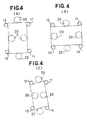
- Figs. 3(A), 3(B) and 3(C) show various variations regarding the winding of the belts 1,2,3 and 4 about the table 20.
- Fig. 3(A) shows a so-called "8"-shaped winding manner.
- the table 20 moves in plane motion within an area indicated by dot-and-dash lines in Fig. 4(A).
- Fig. 3(B) shows a so-called "O"-shaped winding manner.
- Fig. 3(C) shows a winding manner which is to be called a so-called combination type of "8" and "O".
- the table 20 moves in plane motion within an area indicated by dot-and-dash lines in Fig. (4(C).
- the invention should not be limited to the above-described first embodiment, but various modification or variations may be made to the invention.
- the belts 1, 2, 3 and 4 may be not only DD motors, but also DC motors, AC motors, brushless motors or the like.
- the belts 1, 2, 3 and 4 are not directly connected respectively to the motors 21, 22, 23 and 24, but reduction gears may be used between the belts 1, 2, 3 and 4 and the motors 21, 22, 23 and 24. Further, the belts 1, 2, 3 and 4 may be drawn by respective direct-acting piston/cylinder assemblies (not shown).
- Fig. 5 showns a first modification of the above-described first embodiment according to the invention, in which the table 20 is driven by three motors 21, 22 and 23. It will be seen that the table 20 can be moved straight and moved angularly within an area A of the top planar surface 92 of the base 10, which is surrounded by dot-and-dash lines in Fig. 5. That is, the first modification enables the table 20 to occupy any planar position and posture defined by X, Y, ⁇ .
- the cylindrical elements 11, 12 and 13 are provided correspondingly with the belts 1, 2 and 3.
- the tensile directions of the respective belts 1, 2, 3 and 4 the locations where the belts 1, 2, 3 and 4 are connected to the table 20, the vertical positions of the respective belts 1, 2, 3 and 4 and the vertical positions of the respective grooves 61, 62, 63, 64, 71, 72, 73 and 74 can also suitably be modified.
- the (X, Y, ⁇ ) motion is possible, if the belts 1, 2, 3 and 4 are connected to the table 20 in the arrangements illustrated respectively in Figs. 3(B) and 3(C).
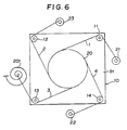
- Fig. 6 shows a second modification of the first embodiment illustrated in Fig. 1.
- an helical spring 201 is substituted for one of the drive motors 21, 22, 23 and 24.
- the helical spring 201 always applies a tension force to the belt 3, i.e., to the table 20.
- the helical spring 201 has intensity or spring constant which may suitably be set depending upon the weight of the table 20 or a subject load applied to the helical spring 201. Of course two or more helical springs may be substituted respectively for two of more drive motors 21, 22, 23 and 24.
- the (X, Y, ⁇ ) motion of the table 20 is determined only depending upon the tensile directions of the respective belts 1, 2, 3 and 4 or 1, 2 and 3. Accordingly, if the cylindrical elements 11, 12, 13 and 14 or 11, 12 and 13 are defined or determined in position, there is produced such a degree of freedom that the drive motors 21, 22, 23 and 24 or 21, 22 and 23 may be placed or arranged anywhere.
- the cylindrical elements 11, 12, 13 and 14 should be placed respectively at corners of an elongated rectangle.
- the table 20 has an angular or square configuration in cross-section which hinders pulling or tesnion of the belts 1, 2, 3 and 4 or 1, 2 and 3, there is no problems if the belt grooves 61, 62, 63 and 64 have adequate radii of curvature, and if the lengths of the respective belts 1, 2, 3 and 4 or 1, 2 and 3 are suitably determined.
- the speed and the tension of each of the drive motors 21, 22, 23 and 24 or 21, 22 and 23 are so programmed as to be corrected automatically depending upon rotational speed of a tool, a configuration of a workpiece, material and the kind of the used tool and the like, there can be provided necessary and sufficient constancy.
- the arrangement may be such that a plurality of sensors are provided for detecting items such as length, tension and the like of respective belts, and the position and posture of the table 20, and three elements or factors (X, Y, and Rotational Torque) applied to the table 20 are obtained by computation, so that feedback control is made possible.
- Figs. 7(A) and 7(B) show a plane motion mechanism according to a second embodiment of the invention.
- the planar motion mechanism comprises a base 40 having a top planar surface 301, and a table 41 mounted on the top planar surface 301 of the base 40.
- a pair of endless belts 42 and 43 are wound about an outer peripheral side surface of the table 41 to drive the same.
- the endless belt 42 passes about a pair of motor pulleys 44 and 45.
- a pair of tension pulleys 51 and 52 urge the endless belt 42 respectively against the pair of motor pulleys 44 and 45.
- the endless belt 43 passes about a pair of motor pulleys 46 and 47.
- a pair of tension pulleys 53 and 54 urge the endless belt 43 respectively against the pair of motor pulleys 46 and 47.
- the base 40 and the table 41 have the same construction as the base 10 and the table 20 of the above-described first embodiment. In the arrangement illustrated in Fig. 7(A), however, it is unnecessary to form grooves, along which the endless belts 42 and 43 extend, in the outer peripheral side surface of the table 41.
- the endless belts 42 and 43 may be wound about the table 41 in a two-stage manner, as shown in Fig. 8(A).
- the arrangement may be such that the endless belt 42 is divided into a pair of endless belt sections 312 and 313.
- the endless belt 43 and the pair of endless belt sections 312 and 313 are wound about the table 41 in a three-stage manner such that the endless belt 43 extends between the pair of endless belt sections 312 and 313.
- the endless belts 42 and 43 are made of steel belts, for example.
- an antislipping element such as rubber, coating or the like is applied to the contact surface of each of the endless belts 42 and 43.
- the endless belts 42 and 43 may be timing belts, perforation belts or the like.
- the plane motion mechanism according to the above-described second embodiment uses the endless belts 42 and 43, there is no limit in the number of revolution of the table 41 on the top planar surface 301 of the base 40. Accordingly, it is possible to realize more free motion of the table 41 with an extremely simple arrangement.
- the plane motion mechanism using the endless belts 42 and 43 has the following disadvantage.
- the endless belt 43 largely deflects on the side toward which the table 41 moves when it is desired to move the table 41 to the right.
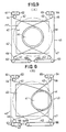
- Figs. 9(A) and 9(B) show a first modification of the second embodiment illustrated in Figs. 7(A) and 7(B), which can prevent the endless belts 42 and 43 from being deflected.
- the first modification illustrated in Figs. 9(A), 9(B), 9(C) and 9(D) is the same in arrangement as the second embodiment.
- the table 41 is mounted on the top planar surface 301 of the base 40, the pair of endless belts 42 and 43 are wound about the table 41, and the motor pulleys 44 through 47 drive the pair of endless belts 42 and 43.
- the endless belt 42 passes about a tension roller 68 through three guide rollers 61, 62 and 63.
- the endless belt 43 passes about a tension roller 69 through three guide rollers 64, 65 and 66.
- the guide pulleys 61 to 66 are fixed with respect to the base 40, the tension pulleys 68 and 69 are slidable toward and away from each other.
- a coil spring 70 extends between frames of the respective tension pulleys 68 and 69 to pull the same toward each other in order to apply substantially constant tensions respectively to the endless belts 42 and 43.
- Fig. 10 shows an example of an arrangement for returning the table 41 to an original point.
- the arrangement comprises a pair of sliders 75 and 76 which are respectively mounted on the lower surfaces of the respective tension pulleys 68 and 69.
- the pair of sliders 75 and 76 are movable toward and away from each other along a guide rail 79.
- the arrangement is such that the sliders 75 and 76 can simultaneously depress the operators of the respective limit switches 77 and 78 which are arranged in position corresponding to the original position of the table, to detect the original position of the table 41.
- the point, where the sliders 75 and 76 simultaneously depress the operators of the respective limit switches 77 and 78 to turn on an AND circuit is the original point.
- Fig. 11 shows a second modification of the second embodiment illustrated in Figs. 7(A) and 7(B).
- a first belt 401 has one end thereof connected to a drive motor 411.
- the first belt 401 extends about the table 41 on the top planar surface 301 of the base 45.
- the other end of the belt 401 is connected to an output shaft of a drive motor 412.
- a second belt 402 has one end thereof connected to a drive motor 413.
- the second belt 402 extends about the table 41 on the top planar surface 301 of the base 45.
- the other end of the belt 402 is connected to an output shaft of a drive motor 414.
- grooves may be formed in the outer peripheral side surface of the table 41 and in the outer peripheral side surface of each of the output shafts of the respective drive motors 411 to 414
- the plane motion mechanism according to the invention is applicable not only to the automatization of processing machines, assembling machines and inspecting and measuring machines, in factories, but also to other fields such as display of goods, toys and the like.
Landscapes
- Engineering & Computer Science (AREA)
- Mechanical Engineering (AREA)
- General Engineering & Computer Science (AREA)
- Robotics (AREA)
- Physics & Mathematics (AREA)
- General Physics & Mathematics (AREA)
- Automation & Control Theory (AREA)
- Machine Tool Units (AREA)
- Transmission Devices (AREA)
Abstract
Description
- This invention relates to an automatization apparatus for machining processing, assembling, measuring, inspection and the like and, more particularly, to a plane motion mechanism suitable for determining a position and a posture of a table in a plane.
- As it is well known, a motion in a plane has three degrees of freedom. Generally, the motion is realized by the use of three joints. For example, positioning of a workpiece on a machining center is practiced such that a slide table in a Y-direction is mounted on a slide table in an X-direction, and a rotary table in a ϑ-direction is mounted on an assembly including the slide tables in the X- and Y-directions, to control three axes including X, Y and ϑ. This is called an orthogonal coordinate system.
- Further, in a horizontal multiple-joint robot, an upper arm is moved angularly by a shoulder joint through ϑ₁. a front arm is moved angularly by an elbow joint through ϑ₂, and a hand is rotated by a wrist joint through ϑ₃, to control three axes including ϑ₁, ϑ₂ and ϑ₃, thereby obtaining a position and a posture (X, Y, ϑ). The following relationship exists between ϑ₁, ϑ₂ and ϑ₃ and X, Y and ϑ :


- In this manner, in the prior art, the arrangement is such that a second axis is mounted on a motion of a first axis, and the last axis is mounted on an assemble including the first and second axes. For this reason, the axis in the lowermost level must move drive mechanisms and guide mechanisms for the respective upper two level including the second and third axes. Thus, a large power is required.
- Further, in the orthogonal coordinate system, not only an area approximate to an area twice strokes required are necessary, but also a considerable thickness is required because of three levels. Furthermore, there is a problem that the orthogonal coordinate system cannot obtain sufficient speed as compared with the horizontal multiple-joint robot.
- On the one hand, only a small area is required for the horizontal multiple-joint robot. However, there is such a problem that rigidity and accuracy cannot be obtained as compared with the orthogonal coordinate system, because of a cantilever effect.
- It is therefore an object of the invention to provide a plane motion mechanism which can occupy only a small or narrow area and which requires only an extremely thin structure or construction, so that the plane motion mechanism can withstand further high speed, high accuracy and high load.
- According to the invention, there is provided a plane motion mechanism comprising:
a base having a top planar surface;
a table mounted on the top planar surface of the base for movement thereon in plane motion, the table having an outer peripheral side surface;
at least first, second and third, elongated power transmitting means having respective one and other ends, one end portions of the respective first, second and third power transmitting means adjacent respectively to the one ends thereof being wound about the outer peripheral side surface of the table;
at least first and second drive means to which the other ends of the respective first and second power transmitting means are connected respectively, for applying tension forces respectively to the first and second power transmitting means; and
tension-applying means to which the other end of the third power transmitting means is connected, for applying a tension force to the third power transmitting means. - With the arrangement of the invention, it is possible to freely slide the table under winding control of the elongated power transmitting means. Accordingly, there can be provided a plane motion which high speed, high accuracy and high load within a small area and having a thin construction. Further, all the drive means move the table without intervening of other drive means. Thus, there is provided an additional advantage that it is possible to eliminate wasteful energy for moving the other drive means and various guides.
- It is preferable that a plane motion mechanism includes four cylindrical elements having respective cylindrical outer peripheral side surfaces, the cylindrical elements being fixedly mounted on the base respectively at the four corners of the imaginary rectangle on the top planar surface of the base, four belts passing respectively about the cylindrical outer peripheral side surfaces of the respective cylindrical elements so that the four belts are defined in their respective tensile directions.
- With the above arrangement of the invention, when the other end of each of the belts having one end thereof wound about the table is taken up, the table is moved angularly in a direction in which the belt is pulled, or is moved linearly. If the tensile directions of the belts are defined, since the drive means and the table are connected to each other, the table is moved angularly in a predetermined direction or is moved linearly.
- The amount of movement can be controlled by a winding amount of the belts due to the drive means. Assuming that the table is circular in planar cross-section, and the radius of the table is b. In order to restrict the tensile direction of the belts, the cylindrical elements are mounted respectively at corners of the imaginary rectangle so as to extend vertically. Assuming that the radius of the cylindrical element is a, a position of the table is (x, y), a posture of the table is ϑ, and positions of the cylindrical elements include P₁ (x₀, y₀), P₂ (-x₀, y₀), P₃(-x₀, -y₀), P4(x₀, -y₀), then, the lengths of the respective belts to the cylindrical elements can be obtained by the following equations:


- It is preferable that the first, second, third and fourth drive means are drive motors for pulling the four belts, respectively, and the plane motion mechanism further includes a control unit for controlling the first, second, third and fourth drive motors.
- With the above arrangement of the invention, if the four belts are brought respectively to their respective lengths described above, there can be obtained a value of (x, y. ϑ). This is true not only in the case of four points, but also in the case of any optional number of points equal to or higher than three. In view of that, if the lengths of the respective belts, i.e., winding amounts are programmed in the control device of the drive means for each axis, the table is moved on the base in accordance with the program. Thus, the table can occupy free positions and postures. Further, if a tension force is appllied to the belts, there can be provided the constancy of its position and posture in the plane. In the case where a request is not sever with respect to the thickness of the plane motion mechanism, the drive means can directly be mounted on the base at the corners in place of the cylindrical elements.
- Further, according to the plane motion mechanism of the invention, in order improve accuracy of the angular movement of the table, one end of the belt is wound about the table and is fixedly connected thereto. Alternatively, the belts extending through the opposed corners on the base can be wound about the table. In the latter case, it is a necessary condition that the belts cannot slide along the grooves in the table. Furthermore, since the grooves in the table are brought to helical configuration, the thickness of the mechanism increases for necessary rotational speed. On the other hand, it is possible to reduce the length of the belt. Thus, there can be produced such a superior advantage that it is possible to rotate the table through revolutions regardless of the length of the belt.
- On the other hand, in such a control of the table, positioning is possible in the case where the coordinates (x,y,ϑ) of a tool of a lathe or the like is to be controlled. In the case where the control of the table is applied to a tool of a milling machine or the like, which requires continuous rotation, however, it is necessary to wind the belt about the table and direction restricting pulleys through a plurality of turns. Accordingly, the apparent diameter of the table or of the pulleys varies or changes depending upon the number of turns. For this reason, since the actual table diameter and the actual pulley diameter are not equal to the diameter data within the control program, errors can occur in the positional control. Of course, it is possible to successively calculate and correct the variable diameter data from the table position or the like. However, The program to be prepared will become complicated. Further, there is a limit in length in the case of the use of the belt. Accordingly, there occurs a limit also in the rotational speed. Free control of rotation will become difficult.
- According to uke Invention, there is also provided a plane motion mechanism comprising:
a base having a top planar surface;
a table counted on the top planar surface of the base for movement thereon in plane motion, the table being circular in cross-section and having an outer peripheral side surface:
at least a pair of first and second elongated power transmitting means extending in contact with the outer peripheral side surface of the table to generate friction between the first and second power transmitting means and the outer peripheral side surface of the table; and
a pair of drive means for driving the first and second power transmitting means, respectively. - With the above arrangement of the invention, the use of the endless belts enables rotational speed of the table not to be limited. Accordingly, it is possible to control the table more freely. Further, since the table can be controlled in position regardless of the number of turns of the belts, it is possible to realize a plane motion with a accuracy , by means of more simple arrangement.
- Specifically, with the above arrangement of the invention, it possible to calculate the moving direction of the table on the basis of vector composition or analysis of the tensile direction of the endless belt. Furthernore, regarding the rotational speed, there occurs no limit. Accordingly, it is possible to freely move the table within the predetermined area on the table, and it is possible to move angulary the table at a predetermined control position without a limit.
-
- Fig. 1. is a perspective view of a plane motion mechanism according to a first embodiment of the invention;
- Fig. 2 is a fragmentary enlarged view of fig. 1 showing a base and a table mounted on a top planar surface of the base for linear and angular movement thereon,
- Figs. 3(A) to 3(C) are views for explaining how the belts of fig. 1 are wound;
- Figs. 4(A) to 4(C) are views for explaining the moving area or moving range of the table moved under the winding conditions illustrated in Figs. 3(A) to 3(C);
- Fig. 5 is a top plan view showing a first modification of the first embodiment illustrated in Fig. 1;
- Fig. 6 is a top plan view showing a second modification of the first embodiment illustrated in Fig. 1.
- Figs. 7(A) and 7(B) are views for explaining a plane motion mechanism according to a second embodiment of the invention , said embodiment using endless belts;
- Figs. 8(A) and 8(B) are views showing how the endless belts illustrated in Figs. 7(A) and 7(B) are wound about the table;
- Figs. 9(A) to (9D) are views showing a first modification of the second embodiment illustrated in Figs. 7(A) and 7(B);
- Fig. 10 is a fragmentary side elevational view showing an example of a tension mechanism illustrated in Figs. 9(A) to 9(D);
- Fig. 11 is a view showing a second modification of the second embodiment illustrated in Figs. 7(A) and 7(B).
- Referring first to Fig. 1, there is shown a plane motion mechanism according to a first embodiment of the invention.
- The plane motion mechanism comprise a base 10 having a top
planar surface 91. Thebase 10 is mounted at a predetermined position in the vertical direction. A table 20 having a circular outerperipheral side surface 92 is mounted on the topplanar surface 91 of thebase 10 for linear movement and angular movement about an axis 25 thereon in plane motion. Fourcylindrical elements respective axes axes cylindrical elements planar surface 91 of the base 10 respectively the four corners of an imaginary rectangle on the topplanar surface 91 of thebase 10. First, second, third and four elongated power transmitting means, that is, fourbelts cylindrical elements belts - The first ends of the
respective belts motors belts control unit 30 is provided for controlling thedrive motors drive motors drive motors - The
drive motors respective output shafts respective belts belts cylindrical elements respective belts peripheral side surface 92 of the table 20 at their respective predetermined locations. In this connection, if thebelts belt grooves respective belts peripheral side surface 92 of the table 20 respectively along thebelt grooves belts cylindrical elements belt grooves belts belt grooves cylindrical element - In this connection, in the case where the
belts output shafts respective motors output shafts output shafts respective motors - As shown in Fig. 2, in order to smoothly move linearly and move angularly the table 20 on the top
planar surface 91 of thebase 10, relief means is provided for relieving friction between the topplanar surface 91 of thebase 10 and the lower surface of the table 20. The relief means is made of a polytetrafluoroethylene film 81 (trade name: Teflon) or the like which is mounted on the lower surface of the table 20. Further, the lower surface of thepolytetrafluoroethylene film 81 is formed with a plurality ofgrooves 82 for retaining a film of lubricant. - Referring back to Fig. 1, the
belts respective belt grooves cylindrical elements belts belt 1 is fixedly connected to the outerperipheral side surface 92 of the table 20 at apoint 38 remotest from thecylindrical element 11 which is mounted on the topplanar surface 91 of the base 10 at at the right upper corner of the base and passes on theuppermost groove 71 in t he cylindricalelement 11. If thebalt 1 extends about the outerperipheral side surface 92 of the table 20 through at least one turn or revolution along thegroove 61, the table 20 can be moved angularly further through one turn or revolution. The peripheral side surface of each of thecylindrical elements grooves axis - Similarly, the
belt 2 reaches thebelt groove 62 in the outerperipheral side surface 92 of the table 20 via thesecond belt groove 72 in the outer peripheral side surface of thecylindrical element 12. Thebelt 2 passes about thebelt groove 62 through one turn or revolution and, subsequently, is fixedly connected to the table 20 at afixing point 39. The same is applicable to thebelts - In order to move the table 20 to the right, the
drive motors belts other drive motors belts belts output shafts motors belts belts belts belts 
- In connection with the above, the amount of movement of the table 20 is determined depending upon the lenghts of the
respective belts respective belts control unit 30. Paths of therespective belts drive motors - According to the plane motion mechanism constructed as described above, the paths of the
respective belts control unit 30, whereby it is possible to slide the table 20 freely to the position and posture defined by (X, Y, ϑ). - Furthermore, since the
drive motors - Figs. 3(A), 3(B) and 3(C) show various variations regarding the winding of the
belts belts belts belts - In connection with the above, the invention should not be limited to the above-described first embodiment, but various modification or variations may be made to the invention. For example, it is possible to use ball bearings, magnetic levitation, air bearings or the like, as means for moving linearly and moving angularly the table 20 in a smooth manner. Further, it is possible to substitute chains and piano wires to the
belts belts drive motors belts motors belts motors belts - Fig. 5 showns a first modification of the above-described first embodiment according to the invention, in which the table 20 is driven by three
motors planar surface 92 of thebase 10, which is surrounded by dot-and-dash lines in Fig. 5. That is, the first modification enables the table 20 to occupy any planar position and posture defined by X, Y, ϑ. In this connection, in the modification shown in Fig. 5, thecylindrical elements belts - Referring back to Fig. 1, it is clear that the tensile directions of the
respective belts belts respective belts respective grooves belts - Fig. 6 shows a second modification of the first embodiment illustrated in Fig. 1. In the second modification, an
helical spring 201 is substituted for one of thedrive motors helical spring 201 always applies a tension force to thebelt 3, i.e., to the table 20. Thehelical spring 201 has intensity or spring constant which may suitably be set depending upon the weight of the table 20 or a subject load applied to thehelical spring 201. Of course two or more helical springs may be substituted respectively for two ofmore drive motors - In the first embodiment and the first and second modifications, the (X, Y, ϑ) motion of the table 20 is determined only depending upon the tensile directions of the
respective belts cylindrical elements drive motors - In connection with the above, if it is desired to move the table 20 within a square surface on the top
planar surface 91 of thebase 10, thecylindrical elements - Furthermore, even if the table 20 has an angular or square configuration in cross-section which hinders pulling or tesnion of the
belts belt grooves respective belts - If, when teaching the paths of the
respective belts control unit 30, the speed and the tension of each of thedrive motors - Figs. 7(A) and 7(B) show a plane motion mechanism according to a second embodiment of the invention. The planar motion mechanism comprises a base 40 having a top
planar surface 301, and a table 41 mounted on the topplanar surface 301 of thebase 40. A pair ofendless belts endless belt 42 passes about a pair of motor pulleys 44 and 45. A pair of tension pulleys 51 and 52 urge theendless belt 42 respectively against the pair of motor pulleys 44 and 45. Similarly, theendless belt 43 passes about a pair of motor pulleys 46 and 47. A pair of tension pulleys 53 and 54 urge theendless belt 43 respectively against the pair of motor pulleys 46 and 47. - The
base 40 and the table 41 have the same construction as thebase 10 and the table 20 of the above-described first embodiment. In the arrangement illustrated in Fig. 7(A), however, it is unnecessary to form grooves, along which theendless belts endless belts endless belt 42 is divided into a pair ofendless belt sections endless belt 43 and the pair ofendless belt sections endless belt 43 extends between the pair ofendless belt sections endless belts endless belt sections - The
endless belts endless belts endless belts endless belts - In the plane motion mechanism constructed as described above according to the second embodiment of the invention, if rotational or angular movement directions, rotational or angular movement speeds and the like of the respective motor pulleys 44 through 47 are programmed beforehand, it is possible to control linear or straight movement and angular movement of the table 41, similarly to the aforesaid first embodiment illustrated in Fig. 1. Of course the motion of the table 41 can be controlled by a manual controller such as a joy stick or the like.
- Since the plane motion mechanism according to the above-described second embodiment uses the
endless belts planar surface 301 of thebase 40. Accordingly, it is possible to realize more free motion of the table 41 with an extremely simple arrangement. - By the way, the plane motion mechanism using the
endless belts endless belt 43 largely deflects on the side toward which the table 41 moves when it is desired to move the table 41 to the right. Figs. 9(A) and 9(B) show a first modification of the second embodiment illustrated in Figs. 7(A) and 7(B), which can prevent theendless belts planar surface 301 of thebase 40, the pair ofendless belts endless belts - The
endless belt 42 passes about atension roller 68 through threeguide rollers endless belt 43 passes about atension roller 69 through threeguide rollers base 40, the tension pulleys 68 and 69 are slidable toward and away from each other. As shown in Figs. 9(C) and 9(D), acoil spring 70 extends between frames of the respective tension pulleys 68 and 69 to pull the same toward each other in order to apply substantially constant tensions respectively to theendless belts - Accordingly, when the table 41 is moved to the right, for example, as shown in Fig. 9(B), slackening or loosening of the
endless belt 43 increases, while slackening of theendless belt 42 decreases. By the decrease in slackening of theendless belt 42, thetension pulley 68 is moved to the left in Fig. 9(B). By the increase in slackening of theendless belt 43 and the tension force of thecoil spring 70, thetension pulley 69 is also moved to the left. The difference in increasing and decreasing rate of slackening of theendless belts coil spring 70. - In the manner described above, if the table 41 is moved to the left, an assembly including the tension pulleys 68 and 69 and the
coil spring 70 is moved to the right, while, if the table 41 is moved to the right, the assembly is moved to the left. In this connection, the table 41 can be moved within an area of maximum motion indicated by the broken line M illustrated in Figs. 9(A) and 9(B). - Fig. 10 shows an example of an arrangement for returning the table 41 to an original point. The arrangement comprises a pair of
sliders sliders guide rail 79. The arrangement is such that thesliders respective limit switches sliders respective limit switches - In the case of the belt control illustrated in Fig. 1, it is necessary to detect the number of turns or revolutions of the belts to be rewound and to return the number of turns at the original point. Thus, the program control becomes cumbersome. Further, in the case where the power supply source is turned off intermediataly, data corresponding to the belt lengths are erased. Thus, there is a case where it is difficult to return the table to the original point. However, in the case where the belts are formed respectively by endless belts, it is unnecessary to rewind the endless belts about the table through one or more turns. Thus, there is produced the advantage that it is unnecessary to control rotational speed of the table 41.
- Fig. 11 shows a second modification of the second embodiment illustrated in Figs. 7(A) and 7(B). In the second modification, a
first belt 401 has one end thereof connected to adrive motor 411. Thefirst belt 401 extends about the table 41 on the topplanar surface 301 of thebase 45. The other end of thebelt 401 is connected to an output shaft of adrive motor 412. Similarly, asecond belt 402 has one end thereof connected to adrive motor 413. Thesecond belt 402 extends about the table 41 on the topplanar surface 301 of thebase 45. The other end of thebelt 402 is connected to an output shaft of adrive motor 414. Of course, grooves may be formed in the outer peripheral side surface of the table 41 and in the outer peripheral side surface of each of the output shafts of therespective drive motors 411 to 414 - In connection with the above, the plane motion mechanism according to the invention is applicable not only to the automatization of processing machines, assembling machines and inspecting and measuring machines, in factories, but also to other fields such as display of goods, toys and the like.
Claims (33)
- A plane motion mechanism comprising:
a base (10) having a top planar surface (91);
a table (20) mounted on said top planar surface of said base for movement thereon in plane motion, said table having an outer peripheral side surface;
at least first (1), second (2) and third (3), elongated power transmitting means having respective first and second ends, the first end portions of the respective first (1), second (2) and third (3) power transmitting means adjacent respectively to said first ends thereof being wound about said outer peripheral side surface of said table (20);
at least first and second drive means (21 to 24) to which the second ends of the respective first (1) and second (2) power transmitting means are connected respectively, for applying tension forces respectively to said first and second power transmitting means; and
tension-applying means (21 to 24) to which the second end of said third power transmitting means (3) is connected, for applying a tension force to said third power transmitting means. - A plane motion mechanism according to claim 1, wherein said first and second drive means (21 to 24) have their respective output shafts (31 to 34), the second end portions of the respective first and second power transmitting means adjacent respectively to the second ends (1 to 4) thereof being wound respectively about said output shafts.
- A plane motion mechanism according to claim 2, wherein said tension-applying means is third drive means (21 to 24) having its output shaft (31 to 34), the second end portion of said third power transmitting means adjacent to the second end thereof being wound about said output shaft of said third drive means.
- A plane motion mechanism according to claim 3, wherein the outer peripheral surfaces of said output shafts (31 to 34) of the respective first, second and third drive means (21 to 24) are formed, with a plurality of grooves, the second end portions of the respective first, second and third power transmitting means (21 to 24) being wound respectively about said output shafts of the respective first, second and third drive means, along said grooves.
- A plane motion mechanism according to claim 1, wherein said outer peripheral side surface of said table (20) is formed therein with a plurality of grooves (61 to 64), said first, second and third power transmitting means (21 to 24) having the respective first end portions which are wound about said outer peripheral side surface of said table along said grooves.
- A plane motion mechanism according to claim 5, wherein said grooves (61 to 64) formed in the outer peripheral side surface of said table are annular in plan.
- A plane motion mechanism according to claim 5, wherein said grooves (61 to 64) formed in the outer peripheral side surface of said table are substantially circular in plan.
- A plane motion mechanism according to claim 1, wherein said tension-applying means is a third drive means (21 to 24) to which the second end of said third power transmitting means is connected for applying the tension force to said third power transmitting means (1 to 4), and wherein said plane motion mechanism further includes fourth elongated power transmitting means (21 to 24) having first and second ends, the first end portion of the fourth power transmitting means adjacent to said first end thereof being wound about said outer peripheral side surface of said table (20), and fourth drive means (21 to 24) to which the second end of said fourth power transmitting means is connected for applying a tension force to said fourth power transmitting means.
- A plane motion mechanism according to claim 8, wherein said first, second, third and fourth power transmitting means are four belts (1 to 4), respectively, extending between said table (20) and said first, second, third and fourth drive means (21 to 24) through four points which are located respectively at four corners of an imaginary rectangle on said top planar surface (91) of said base (10), wherein said belts have their respective first and second ends, first end portions of the respective belts adjacent respectively to the first ends thereof being wound about said outer peripheral side surface of said table (20), and wherein said first, second, third and fourth drive means (21 to 24) control independently tensions applied respectively to said first end portions of the respective belts (1 to 4) which are to be wound about said outer peripheral side surface of said table.
- A plane motion mechanism according to claim 9, further including four cylindrical elements (11 to 14) having respective cylindrical outer peripheral side surfaces, said cylindrical elements being fixedly mounted to said base (10) respectively at said four corners of said imaginary rectangle on said top planar surface of said base, said four belts (1 to 4) passing respectively about said cylindrical outer peripheral side surfaces of the respective cylindrical elements so that said four belts are defined in their respective tensile directions.
- A plane motion mechanism according to claim 9, wherein said first, second, third and fourth drive means are drive motors (21 to 24) for pulling said four belts (1 to 4), respectively, and wherein said plane motion mechanism further includes a control unit (30) for controlling said first, second, third and fourth drive motors.
- A plane motion mechanism according to claim 11, wherein said drive motors (21 to 24) have respective output shafts (31 to 34) to which the second ends of the respective belts (1 to 4) are fixedly connected, said belts extending respectively about said cylindrical elements (11 to 14), the first ends of the respective belts being fixedly connected to said outer peripheral side surface of said table (20) at their respective predetermined locations (38, 39).
- A plane motion mechanism according to claim 10, wherein the outer peripheral side surface of said table (20) is formed, with a plurality of belt grooves (61 to 64), said first end portions of the respective belts (1 to 4) being wound about said outer peripheral side surface of said table respectively along said belt grooves so that said belts are regulated in their respective vertical positions, and wherein each of said cylindrical elements (11 to 14) is formed, in its outer periphery, with a plurality of belt grooves, each of said belts extending along the corresponding belt groove in the outer periphery of the corresponding cylindrical element.
- A plane motion mechanism according to claim 10, wherein said belts (1 to 4) are fixedly connected to said outer peripheral side surface of said table (20) at respective points (38, 39) remotest from said cylindrical elements (11 to 14).
- A plane motion mechanism according to claim 14, wherein said belts (1 to 4) extend about said outer peripheral side surface of said table (20) at least one turn along said grooves (61 to 64).
- A plane motion mechanism according to claim 1, further including relief means for relieving friction generated between said top planar surface (91) of said base (10) and a lower surface of said table (20).
- A plane motion mechanism according to claim 16, wherein said relief means is a polytetrafluoroethylene film which is mounted to the lower surface of said table (20).
- A plane motion mechanism according to claim 11, wherein said drive motors (21 to 24) are mounted on a side surface of said base so as to extend vertically.
- A plane motion mechanism according to claim 1, wherein each of said first, second and third power transmitting means (1 to 4) is a belt, a piano wire or a chain.
- A plane motion mechanism according to claim 1, wherein each of said first, second and third power transmitting means (1 to 4) is made of an engineering plastic material.
- A plane motion mechanism according to claim 8, wherein each of said first, second and third drive means (21 to 24) is a DD motor, a DC motor, an AC motor or a brushless motor.
- A plane motion mechanism according to claim 1, wherein said tension-applying means is a spring means (201) to which the second end of said third power transmitting means (3) is connected for applying the tension force to said third power transmitting means, and wherein said plane motion mechanism further includes fourth elongated power transmitting means (1 to 4) having first and second ends, a first end portion of the fourth power transmitting means adjacent to said first end thereof being wound about said outer peripheral side surface of said table (20), and fourth drive means (21 to 24) to which the second end of said fourth power transmitting means is connected for applying a tension force to said fourth power transmitting means.
- A plane motion mechanism according to claim 22, wherein said spring means (201) includes a helical spring.
- A plane motion mechanism according to claim 10, wherein the first end of each of said belts (1 to 4) is fixedly connected to the outer peripheral side surface of said table (20) at a point remotest (38) from a corresponding one of said cylindrical elements (11 to 14).
- A plane motion mechanism according to claim 4, wherein each of said grooves has a radius of curvature.
- A plane motion mechanism according to claim 25, wherein each of said belts (1 to 4) extends about the outer peripheral side surface of said table (20) through at least one turn along the groove (61 to 64).
- A plane motion mechanism comprising:
a base (40) having a top planar surface (301);
a table (41) mounted on said top planar surface of said base for movement thereon in plane motion, said table being circular in cross-section and having an outer peripheral side surface;
at least a pair of first (42) and second (43) elongated power transmitting means extending in contact with said outer peripheral side surface of said table to generate friction between said first and second power transmitting means and said outer peripheral side surface of said table; and
a pair of drive means (44,45 ; 46,47) for driving said first and second power transmitting means, respectively. - A plane motion mechanism according to claim 27, wherein each of said pair of drive means (44,45 ; 46,47) includes a pair of drive units, each of said pair of first and second elongated power transmitting means (42, 43) having first and second ends which are connected respectively to a corresponding pair of drive units.
- A plane motion mechanism according to claim 28, wherein each of said pair of drive means (44,45 ; 46,47) includes a pair of drive units, each of said pair of first and second elongated power transmitting means (42, 43) having first and second ends which are fixedly secured respectively to a corresponding pair of drive units.
- A plane motion mechanism according to claim 28, wherein each of said belts (42, 43) is a steel belt, a timing belt or a perforation belt.
- A plane motion mechanism according to claim 28, wherein said belts are endless belts (42, 43) which are wound about said table (41) in a two-stage manner.
- A plane motion mechanism according to claim 28, wherein one of said endless belts is an endless belt which is divided into a pair of endless belt sections (312, 313), and the other belt (43) which is an endless belt and the pair of endless belt sections are wound about said table (41) in a three-stage manner such that the other endless belt (43) extends between the pair of endless belt sections (312, 313).
- A plane motion mechanism according to claim 29, including two pairs of motor pulleys (44 to 47), the pair of belts which are endless belts (42, 43) extending respectively between said two pairs of motor pulleys, said two pairs of motor pulleys driving said pair of endless belts, respectively.
Priority Applications (1)
| Application Number | Priority Date | Filing Date | Title |
|---|---|---|---|
| EP94400069A EP0599827A3 (en) | 1990-07-20 | 1991-07-19 | Plane motion mechanism. |
Applications Claiming Priority (4)
| Application Number | Priority Date | Filing Date | Title |
|---|---|---|---|
| JP190671/90 | 1990-07-20 | ||
| JP19067190 | 1990-07-20 | ||
| JP256037/91 | 1991-07-01 | ||
| JP3256037A JPH05228770A (en) | 1990-07-20 | 1991-07-01 | Plane movement mechanism |
Related Child Applications (1)
| Application Number | Title | Priority Date | Filing Date |
|---|---|---|---|
| EP94400069.4 Division-Into | 1994-01-12 |
Publications (2)
| Publication Number | Publication Date |
|---|---|
| EP0469956A1 true EP0469956A1 (en) | 1992-02-05 |
| EP0469956B1 EP0469956B1 (en) | 1995-10-04 |
Family
ID=26506240
Family Applications (2)
| Application Number | Title | Priority Date | Filing Date |
|---|---|---|---|
| EP94400069A Withdrawn EP0599827A3 (en) | 1990-07-20 | 1991-07-19 | Plane motion mechanism. |
| EP91402027A Expired - Lifetime EP0469956B1 (en) | 1990-07-20 | 1991-07-19 | Plane motion mechanism |
Family Applications Before (1)
| Application Number | Title | Priority Date | Filing Date |
|---|---|---|---|
| EP94400069A Withdrawn EP0599827A3 (en) | 1990-07-20 | 1991-07-19 | Plane motion mechanism. |
Country Status (4)
| Country | Link |
|---|---|
| US (1) | US5148716A (en) |
| EP (2) | EP0599827A3 (en) |
| JP (1) | JPH05228770A (en) |
| DE (1) | DE69113560T2 (en) |
Cited By (2)
| Publication number | Priority date | Publication date | Assignee | Title |
|---|---|---|---|---|
| EP1544911A3 (en) * | 2003-12-17 | 2005-11-23 | Erich Dipl.-Ing. Thallner | Adjusting device |
| WO2015158793A1 (en) * | 2014-04-16 | 2015-10-22 | Asml Netherlands B.V. | Lithographic apparatus, method for positioning an object in a lithographic apparatus and device manufacturing method |
Families Citing this family (4)
| Publication number | Priority date | Publication date | Assignee | Title |
|---|---|---|---|---|
| JPH07156031A (en) * | 1993-12-01 | 1995-06-20 | Micro Tec Kk | XYθ table |
| JP5202278B2 (en) * | 2008-12-19 | 2013-06-05 | アルファーデザイン株式会社 | Positioning device and positioning method |
| JP5974416B2 (en) * | 2011-12-20 | 2016-08-23 | 学校法人立命館 | Wire drive mechanism |
| EP3233390B1 (en) | 2014-12-19 | 2019-02-20 | Fundacíon Tecnalia Research & Innovation | Planar motion device |
Citations (13)
| Publication number | Priority date | Publication date | Assignee | Title |
|---|---|---|---|---|
| US1453903A (en) * | 1922-07-24 | 1923-05-01 | George M Ask | Power-transmitting mechanism |
| FR1022005A (en) * | 1950-07-13 | 1953-02-26 | Control by differential windings with variable speed, acceleration and self-stability | |
| US2786361A (en) * | 1953-01-09 | 1957-03-26 | English Electric Co Ltd | Gimbal mechanisms |
| CH552759A (en) * | 1973-09-07 | 1974-08-15 | Doka Otto | ROPE DRIVE FOR SLIP-FREE TRANSMISSION OF A LINEAR MOTION INTO A ROTARY MOTION. |
| GB2088987A (en) * | 1980-11-12 | 1982-06-16 | Marconi Co Ltd | Drive Systems |
| JPS5861429A (en) * | 1981-10-07 | 1983-04-12 | Toshiba Corp | Moving microphone device |
| EP0158784A1 (en) * | 1984-03-20 | 1985-10-23 | Preh Industrieausrüstungen GmbH | X-Y coordinates positioning device |
| DE3427413C1 (en) * | 1984-07-25 | 1986-01-02 | Dr. Johannes Heidenhain Gmbh, 8225 Traunreut | Probe device |
| JPS61270044A (en) * | 1985-05-24 | 1986-11-29 | Toshiba Corp | Three axes movable stage |
| JPS62281018A (en) * | 1986-05-30 | 1987-12-05 | Nippon Telegr & Teleph Corp <Ntt> | Angle controller |
| EP0293847A2 (en) * | 1987-06-03 | 1988-12-07 | Götz Dipl.-Phys. Heidelberg | Motion converting device |
| JPH0256613A (en) * | 1988-08-22 | 1990-02-26 | Iseki & Co Ltd | Position controller in actuator |
| US4932210A (en) * | 1988-08-19 | 1990-06-12 | The Boeing Company | Shape memory metal precision actuator |
Family Cites Families (7)
| Publication number | Priority date | Publication date | Assignee | Title |
|---|---|---|---|---|
| NL129819C (en) * | 1963-12-06 | |||
| DE1801973A1 (en) * | 1968-10-09 | 1970-06-04 | Zuse Kg | Drum for driving a flexible element |
| US3926061A (en) * | 1974-10-02 | 1975-12-16 | Hewlett Packard Co | Differential drive rotating disc impact printer |
| US4392140A (en) * | 1981-07-20 | 1983-07-05 | General Dynamics, Pomona Division | Dual cable drive rolling arc gimbal |
| USRE32414E (en) * | 1981-12-08 | 1987-05-12 | Zymark Corporation | Robot and control system |
| DE3390346C2 (en) * | 1982-12-01 | 1994-06-23 | Garrett W Brown | Suspension for a television camera |
| GB2210350A (en) * | 1987-09-25 | 1989-06-07 | Kemble Instr Company Limited | Machine drive system |
-
1991
- 1991-07-01 JP JP3256037A patent/JPH05228770A/en active Pending
- 1991-07-17 US US07/731,064 patent/US5148716A/en not_active Expired - Fee Related
- 1991-07-19 EP EP94400069A patent/EP0599827A3/en not_active Withdrawn
- 1991-07-19 EP EP91402027A patent/EP0469956B1/en not_active Expired - Lifetime
- 1991-07-19 DE DE69113560T patent/DE69113560T2/en not_active Expired - Fee Related
Patent Citations (13)
| Publication number | Priority date | Publication date | Assignee | Title |
|---|---|---|---|---|
| US1453903A (en) * | 1922-07-24 | 1923-05-01 | George M Ask | Power-transmitting mechanism |
| FR1022005A (en) * | 1950-07-13 | 1953-02-26 | Control by differential windings with variable speed, acceleration and self-stability | |
| US2786361A (en) * | 1953-01-09 | 1957-03-26 | English Electric Co Ltd | Gimbal mechanisms |
| CH552759A (en) * | 1973-09-07 | 1974-08-15 | Doka Otto | ROPE DRIVE FOR SLIP-FREE TRANSMISSION OF A LINEAR MOTION INTO A ROTARY MOTION. |
| GB2088987A (en) * | 1980-11-12 | 1982-06-16 | Marconi Co Ltd | Drive Systems |
| JPS5861429A (en) * | 1981-10-07 | 1983-04-12 | Toshiba Corp | Moving microphone device |
| EP0158784A1 (en) * | 1984-03-20 | 1985-10-23 | Preh Industrieausrüstungen GmbH | X-Y coordinates positioning device |
| DE3427413C1 (en) * | 1984-07-25 | 1986-01-02 | Dr. Johannes Heidenhain Gmbh, 8225 Traunreut | Probe device |
| JPS61270044A (en) * | 1985-05-24 | 1986-11-29 | Toshiba Corp | Three axes movable stage |
| JPS62281018A (en) * | 1986-05-30 | 1987-12-05 | Nippon Telegr & Teleph Corp <Ntt> | Angle controller |
| EP0293847A2 (en) * | 1987-06-03 | 1988-12-07 | Götz Dipl.-Phys. Heidelberg | Motion converting device |
| US4932210A (en) * | 1988-08-19 | 1990-06-12 | The Boeing Company | Shape memory metal precision actuator |
| JPH0256613A (en) * | 1988-08-22 | 1990-02-26 | Iseki & Co Ltd | Position controller in actuator |
Non-Patent Citations (1)
| Title |
|---|
| SOLID STATE TECHNOLOGY. vol. 11, no. 11, November 1968, WASHINGTON US pages 43 - 45; & P. BIERBAUM: 'A High Precision Alignment Device' * |
Cited By (6)
| Publication number | Priority date | Publication date | Assignee | Title |
|---|---|---|---|---|
| EP1544911A3 (en) * | 2003-12-17 | 2005-11-23 | Erich Dipl.-Ing. Thallner | Adjusting device |
| US7246445B2 (en) | 2003-12-17 | 2007-07-24 | Erich Thallner | Alignment device |
| WO2015158793A1 (en) * | 2014-04-16 | 2015-10-22 | Asml Netherlands B.V. | Lithographic apparatus, method for positioning an object in a lithographic apparatus and device manufacturing method |
| CN106104385A (en) * | 2014-04-16 | 2016-11-09 | Asml荷兰有限公司 | Lithographic apparatus, method for positioning an object in lithographic apparatus, and device manufacturing method |
| US9910367B2 (en) | 2014-04-16 | 2018-03-06 | Asml Netherlands B.V. | Lithographic apparatus, method for positioning an object in a lithographic apparatus and device manufacturing method |
| CN106104385B (en) * | 2014-04-16 | 2018-08-10 | Asml荷兰有限公司 | Lithographic apparatus, method for positioning an object in lithographic apparatus, and device manufacturing method |
Also Published As
| Publication number | Publication date |
|---|---|
| DE69113560T2 (en) | 1996-06-05 |
| US5148716A (en) | 1992-09-22 |
| JPH05228770A (en) | 1993-09-07 |
| DE69113560D1 (en) | 1995-11-09 |
| EP0599827A2 (en) | 1994-06-01 |
| EP0599827A3 (en) | 1995-08-09 |
| EP0469956B1 (en) | 1995-10-04 |
Similar Documents
| Publication | Publication Date | Title |
|---|---|---|
| US6668678B1 (en) | Manipulator | |
| US5062673A (en) | Articulated hand | |
| US5419008A (en) | Ball joint | |
| US10330182B2 (en) | Robot actuator utilizing a differential pulley transmission | |
| US6121743A (en) | Dual robotic arm end effectors having independent yaw motion | |
| US5339749A (en) | Table positioning mechanism | |
| US6068442A (en) | SCARA robot and articulator | |
| KR102344797B1 (en) | 3-Axis Motion Platform | |
| EP1463185B1 (en) | Uniaxial drive unit and surface shape measuring apparatus using the same | |
| JP3046676B2 (en) | An improved strip tension measurement device for use in coilers. | |
| US5148716A (en) | Plane motion mechanism | |
| GB2088987A (en) | Drive Systems | |
| US7343684B2 (en) | Robotic system with traction drive | |
| CN113305825A (en) | Single-degree-of-freedom rope-driven variable-stiffness joint and measurement and control platform thereof | |
| CN112091946A (en) | Overhead multi-degree-of-freedom rope-driven parallel robot | |
| US3170650A (en) | Wire spooling apparatus and method | |
| US20230083630A1 (en) | Working table for reel-to-reel process | |
| EP1398176B1 (en) | High speed marker | |
| US4993997A (en) | Lugged belt driven linear X-Y positioner | |
| EP3106713A1 (en) | Traction arrangement comprising a belt and method for driving the same | |
| CN103802129B (en) | Precise positioning loaded and high speed mechanical arm | |
| GB2151268A (en) | A device for traversing material onto a spool with divergent end flanges | |
| JPH09145342A (en) | Code guide device for linear guide device | |
| CA1245246A (en) | Scara type manipulator apparatus | |
| US20250327510A1 (en) | Cable Drive Linear Positioner |
Legal Events
| Date | Code | Title | Description |
|---|---|---|---|
| PUAI | Public reference made under article 153(3) epc to a published international application that has entered the european phase |
Free format text: ORIGINAL CODE: 0009012 |
|
| AK | Designated contracting states |
Kind code of ref document: A1 Designated state(s): DE FR GB IT SE |
|
| 17P | Request for examination filed |
Effective date: 19920709 |
|
| 17Q | First examination report despatched |
Effective date: 19921130 |
|
| RAP1 | Party data changed (applicant data changed or rights of an application transferred) |
Owner name: UNI DATA LTD. Owner name: NICOTEC CO., LTD. |
|
| GRAA | (expected) grant |
Free format text: ORIGINAL CODE: 0009210 |
|
| AK | Designated contracting states |
Kind code of ref document: B1 Designated state(s): DE FR GB IT SE |
|
| XX | Miscellaneous (additional remarks) |
Free format text: TEILANMELDUNG 94400069.4 EINGEREICHT AM 19/07/91. |
|
| REF | Corresponds to: |
Ref document number: 69113560 Country of ref document: DE Date of ref document: 19951109 |
|
| ITF | It: translation for a ep patent filed | ||
| ET | Fr: translation filed | ||
| PG25 | Lapsed in a contracting state [announced via postgrant information from national office to epo] |
Ref country code: GB Effective date: 19960719 |
|
| PG25 | Lapsed in a contracting state [announced via postgrant information from national office to epo] |
Ref country code: SE Effective date: 19960720 |
|
| PLBE | No opposition filed within time limit |
Free format text: ORIGINAL CODE: 0009261 |
|
| STAA | Information on the status of an ep patent application or granted ep patent |
Free format text: STATUS: NO OPPOSITION FILED WITHIN TIME LIMIT |
|
| 26N | No opposition filed | ||
| GBPC | Gb: european patent ceased through non-payment of renewal fee |
Effective date: 19960719 |
|
| PG25 | Lapsed in a contracting state [announced via postgrant information from national office to epo] |
Ref country code: FR Effective date: 19970328 |
|
| PG25 | Lapsed in a contracting state [announced via postgrant information from national office to epo] |
Ref country code: DE Effective date: 19970402 |
|
| EUG | Se: european patent has lapsed |
Ref document number: 91402027.6 |
|
| REG | Reference to a national code |
Ref country code: FR Ref legal event code: ST |
|
| PG25 | Lapsed in a contracting state [announced via postgrant information from national office to epo] |
Ref country code: IT Free format text: LAPSE BECAUSE OF NON-PAYMENT OF DUE FEES;WARNING: LAPSES OF ITALIAN PATENTS WITH EFFECTIVE DATE BEFORE 2007 MAY HAVE OCCURRED AT ANY TIME BEFORE 2007. THE CORRECT EFFECTIVE DATE MAY BE DIFFERENT FROM THE ONE RECORDED. Effective date: 20050719 |