EP0468500B1 - Oxygen concentration detector - Google Patents
Oxygen concentration detector Download PDFInfo
- Publication number
- EP0468500B1 EP0468500B1 EP91112512A EP91112512A EP0468500B1 EP 0468500 B1 EP0468500 B1 EP 0468500B1 EP 91112512 A EP91112512 A EP 91112512A EP 91112512 A EP91112512 A EP 91112512A EP 0468500 B1 EP0468500 B1 EP 0468500B1
- Authority
- EP
- European Patent Office
- Prior art keywords
- electrode
- diffusion
- oxygen concentration
- solid electrolyte
- layer
- Prior art date
- Legal status (The legal status is an assumption and is not a legal conclusion. Google has not performed a legal analysis and makes no representation as to the accuracy of the status listed.)
- Expired - Lifetime
Links
- 239000001301 oxygen Substances 0.000 title claims description 57
- 229910052760 oxygen Inorganic materials 0.000 title claims description 57
- QVGXLLKOCUKJST-UHFFFAOYSA-N atomic oxygen Chemical compound [O] QVGXLLKOCUKJST-UHFFFAOYSA-N 0.000 title claims description 53
- MCMNRKCIXSYSNV-UHFFFAOYSA-N Zirconium dioxide Chemical compound O=[Zr]=O MCMNRKCIXSYSNV-UHFFFAOYSA-N 0.000 claims description 96
- 238000009792 diffusion process Methods 0.000 claims description 49
- PNEYBMLMFCGWSK-UHFFFAOYSA-N aluminium oxide Inorganic materials [O-2].[O-2].[O-2].[Al+3].[Al+3] PNEYBMLMFCGWSK-UHFFFAOYSA-N 0.000 claims description 40
- 239000007789 gas Substances 0.000 claims description 31
- 239000007784 solid electrolyte Substances 0.000 claims description 15
- 239000000463 material Substances 0.000 claims description 6
- 239000004020 conductor Substances 0.000 claims description 4
- 238000003411 electrode reaction Methods 0.000 claims description 3
- 239000012777 electrically insulating material Substances 0.000 claims 1
- 239000003381 stabilizer Substances 0.000 claims 1
- BASFCYQUMIYNBI-UHFFFAOYSA-N platinum Chemical compound [Pt] BASFCYQUMIYNBI-UHFFFAOYSA-N 0.000 description 48
- 229910052697 platinum Inorganic materials 0.000 description 24
- 238000000576 coating method Methods 0.000 description 7
- 239000011248 coating agent Substances 0.000 description 6
- 238000010586 diagram Methods 0.000 description 6
- 238000000034 method Methods 0.000 description 6
- 229910002077 partially stabilized zirconia Inorganic materials 0.000 description 6
- MYMOFIZGZYHOMD-UHFFFAOYSA-N Dioxygen Chemical compound O=O MYMOFIZGZYHOMD-UHFFFAOYSA-N 0.000 description 4
- DOIRQSBPFJWKBE-UHFFFAOYSA-N dibutyl phthalate Chemical compound CCCCOC(=O)C1=CC=CC=C1C(=O)OCCCC DOIRQSBPFJWKBE-UHFFFAOYSA-N 0.000 description 4
- 229910001882 dioxygen Inorganic materials 0.000 description 4
- HEPLMSKRHVKCAQ-UHFFFAOYSA-N lead nickel Chemical compound [Ni].[Pb] HEPLMSKRHVKCAQ-UHFFFAOYSA-N 0.000 description 4
- -1 oxygen ions Chemical class 0.000 description 4
- 239000002245 particle Substances 0.000 description 4
- LFQSCWFLJHTTHZ-UHFFFAOYSA-N Ethanol Chemical compound CCO LFQSCWFLJHTTHZ-UHFFFAOYSA-N 0.000 description 3
- 239000000853 adhesive Substances 0.000 description 3
- 230000001070 adhesive effect Effects 0.000 description 3
- 238000010304 firing Methods 0.000 description 3
- 229910044991 metal oxide Inorganic materials 0.000 description 3
- 150000004706 metal oxides Chemical class 0.000 description 3
- 239000011148 porous material Substances 0.000 description 3
- 238000007639 printing Methods 0.000 description 3
- LRHPLDYGYMQRHN-UHFFFAOYSA-N N-Butanol Chemical compound CCCCO LRHPLDYGYMQRHN-UHFFFAOYSA-N 0.000 description 2
- VYPSYNLAJGMNEJ-UHFFFAOYSA-N Silicium dioxide Chemical compound O=[Si]=O VYPSYNLAJGMNEJ-UHFFFAOYSA-N 0.000 description 2
- 230000015572 biosynthetic process Effects 0.000 description 2
- 239000003638 chemical reducing agent Substances 0.000 description 2
- 238000005229 chemical vapour deposition Methods 0.000 description 2
- 238000002474 experimental method Methods 0.000 description 2
- 239000012212 insulator Substances 0.000 description 2
- 239000010416 ion conductor Substances 0.000 description 2
- 238000004519 manufacturing process Methods 0.000 description 2
- 238000001000 micrograph Methods 0.000 description 2
- 239000007800 oxidant agent Substances 0.000 description 2
- 230000001590 oxidative effect Effects 0.000 description 2
- 239000003870 refractory metal Substances 0.000 description 2
- 238000007650 screen-printing Methods 0.000 description 2
- 229910017944 Ag—Cu Inorganic materials 0.000 description 1
- 239000001856 Ethyl cellulose Substances 0.000 description 1
- ZZSNKZQZMQGXPY-UHFFFAOYSA-N Ethyl cellulose Chemical compound CCOCC1OC(OC)C(OCC)C(OCC)C1OC1C(O)C(O)C(OC)C(CO)O1 ZZSNKZQZMQGXPY-UHFFFAOYSA-N 0.000 description 1
- 229910026161 MgAl2O4 Inorganic materials 0.000 description 1
- 239000004147 Sorbitan trioleate Substances 0.000 description 1
- PRXRUNOAOLTIEF-ADSICKODSA-N Sorbitan trioleate Chemical compound CCCCCCCC\C=C/CCCCCCCC(=O)OC[C@@H](OC(=O)CCCCCCC\C=C/CCCCCCCC)[C@H]1OC[C@H](O)[C@H]1OC(=O)CCCCCCC\C=C/CCCCCCCC PRXRUNOAOLTIEF-ADSICKODSA-N 0.000 description 1
- XSTXAVWGXDQKEL-UHFFFAOYSA-N Trichloroethylene Chemical group ClC=C(Cl)Cl XSTXAVWGXDQKEL-UHFFFAOYSA-N 0.000 description 1
- WUOACPNHFRMFPN-UHFFFAOYSA-N alpha-terpineol Chemical compound CC1=CCC(C(C)(C)O)CC1 WUOACPNHFRMFPN-UHFFFAOYSA-N 0.000 description 1
- 238000005219 brazing Methods 0.000 description 1
- 229910052681 coesite Inorganic materials 0.000 description 1
- 238000002485 combustion reaction Methods 0.000 description 1
- 230000000052 comparative effect Effects 0.000 description 1
- 239000013256 coordination polymer Substances 0.000 description 1
- 229910052593 corundum Inorganic materials 0.000 description 1
- 229910052906 cristobalite Inorganic materials 0.000 description 1
- 238000005520 cutting process Methods 0.000 description 1
- 238000002484 cyclic voltammetry Methods 0.000 description 1
- SQIFACVGCPWBQZ-UHFFFAOYSA-N delta-terpineol Natural products CC(C)(O)C1CCC(=C)CC1 SQIFACVGCPWBQZ-UHFFFAOYSA-N 0.000 description 1
- 238000000151 deposition Methods 0.000 description 1
- 230000008021 deposition Effects 0.000 description 1
- 230000027734 detection of oxygen Effects 0.000 description 1
- 238000007606 doctor blade method Methods 0.000 description 1
- 230000000694 effects Effects 0.000 description 1
- 230000005518 electrochemistry Effects 0.000 description 1
- 235000019325 ethyl cellulose Nutrition 0.000 description 1
- 229920001249 ethyl cellulose Polymers 0.000 description 1
- 239000011810 insulating material Substances 0.000 description 1
- 150000002500 ions Chemical class 0.000 description 1
- 238000004898 kneading Methods 0.000 description 1
- 238000003475 lamination Methods 0.000 description 1
- 238000005259 measurement Methods 0.000 description 1
- 239000000203 mixture Substances 0.000 description 1
- TWNQGVIAIRXVLR-UHFFFAOYSA-N oxo(oxoalumanyloxy)alumane Chemical compound O=[Al]O[Al]=O TWNQGVIAIRXVLR-UHFFFAOYSA-N 0.000 description 1
- 239000000377 silicon dioxide Substances 0.000 description 1
- 235000019337 sorbitan trioleate Nutrition 0.000 description 1
- 229960000391 sorbitan trioleate Drugs 0.000 description 1
- 229910052596 spinel Inorganic materials 0.000 description 1
- 238000004544 sputter deposition Methods 0.000 description 1
- 229910001220 stainless steel Inorganic materials 0.000 description 1
- 239000010935 stainless steel Substances 0.000 description 1
- 229910052682 stishovite Inorganic materials 0.000 description 1
- 239000000126 substance Substances 0.000 description 1
- 229940116411 terpineol Drugs 0.000 description 1
- UBOXGVDOUJQMTN-UHFFFAOYSA-N trichloroethylene Natural products ClCC(Cl)Cl UBOXGVDOUJQMTN-UHFFFAOYSA-N 0.000 description 1
- 229910052905 tridymite Inorganic materials 0.000 description 1
- WFKWXMTUELFFGS-UHFFFAOYSA-N tungsten Chemical compound [W] WFKWXMTUELFFGS-UHFFFAOYSA-N 0.000 description 1
- 229910052721 tungsten Inorganic materials 0.000 description 1
- 239000010937 tungsten Substances 0.000 description 1
- XLYOFNOQVPJJNP-UHFFFAOYSA-N water Substances O XLYOFNOQVPJJNP-UHFFFAOYSA-N 0.000 description 1
- 238000003466 welding Methods 0.000 description 1
- 229910001845 yogo sapphire Inorganic materials 0.000 description 1
Images




Classifications
-
- G—PHYSICS
- G01—MEASURING; TESTING
- G01N—INVESTIGATING OR ANALYSING MATERIALS BY DETERMINING THEIR CHEMICAL OR PHYSICAL PROPERTIES
- G01N27/00—Investigating or analysing materials by the use of electric, electrochemical, or magnetic means
- G01N27/26—Investigating or analysing materials by the use of electric, electrochemical, or magnetic means by investigating electrochemical variables; by using electrolysis or electrophoresis
- G01N27/403—Cells and electrode assemblies
- G01N27/406—Cells and probes with solid electrolytes
- G01N27/407—Cells and probes with solid electrolytes for investigating or analysing gases
- G01N27/4075—Composition or fabrication of the electrodes and coatings thereon, e.g. catalysts
Definitions
- the present invention relates to an oxygen concentration detector which detects an oxygen concentration of a sample gas from, for example, burners for hot water or internal combustion engines.
- the detector shows no region of constant current against voltage changes, i.e. flat current region, as shown in Fig. 13, that is, no good limit current characteristics can be obtained.
- Fig. 13 shows the data obtained with platinum electrodes coated only with alumina as a diffusion-resistant layer.
- JP-A-61-45962 proposes to provide a zirconia diffusion-resistant layer on a zirconia element in view of differences in shrinkage and thermal expansion coefficient at the firing.
- a constant current region flat region
- occurrence of large hysteresis in the voltage-current characteristics is a problem as obvious from Fig. 14.
- an electromotive-force type oxygen concentration detector comprising an oxygen concentration sensor made of an oxygen ion-conductive metal oxide, which is provided with an electrode on two opposite sides thereof and, further, has a first porous coating of a refractory metal oxide formed on the surface of the electrode which is to be exposed to the gas under test, and a second porous coating of a refractory metal oxide formed on the surface of the first coating, said second coating having a number of pores which are larger than the pores of the first coating.
- the present invention has been accomplished to solve the foregoing problems.
- An object of the present invention is to provide an oxygen concentration detector for accurately detecting an oxygen concentration of a gas with distinguished current-voltage characteristics free from the hysteresis.
- the present invention provides an oxygen concentration detector which comprises
- the present invention provides an oxygen concentration detector, further comprising
- an electrically insulating, porous layer is provided between the electrode and the diffusion-resistant layer to exert an electrically insulating action, and thus no O 2- is produced in the diffusion-resistant layer and no hysteresis is formed.
- Fig. 1 is a cross-sectional view of a sensor structure according to one embodiment of the present invention.
- Fig. 2 is a perspective view of the sensor device according to the embodiment.
- Fig. 3 is a perspective view of dismantled sensor device according to the embodiment.
- Fig. 4 is a process flow sheet showing steps of making the zirconia element according to the embodiment.
- Fig. 5 is a process flow sheet showing steps of making a device according to the embodiment.
- Fig. 6 is a process flow sheet showing steps of making a complete oxygen concentration detector according to the embodiment.
- Fig. 7 is a schematic cross-sectional view showing the essential parts in the sensor device according to the embodiment.
- Fig. 8 is a micrograph showing the structure of the sintered essential parts corresponding to the parts shown in Fig. 7.
- Fig. 9 is a diagram showing the current-voltage characteristics of the oxygen concentration detector made in the foregoing embodiment of the present invention.
- Fig. 10 is a schematic view showing the principle of function of a conventional oxygen concentration detector.
- Fig. 11 is a schematic view showing the principle of function of the oxygen concentration device made in the foregoing embodiment of the present invention.
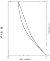
- Fig. 12 is a diagram showing the current-voltage characteristics of a comparative oxygen concentration detector.
- Fig. 13 is a diagram showing the current-voltage characteristics of a conventional oxygen concentration detector with a diffusion-resistant layer of alumina.
- Fig. 14 is a diagram showing the current-voltage characteristics of a conventional oxygen concentration detector with a diffusion-resistant layer of zirconia.
- Fig. 1 is a cross-sectional view of the essential parts of a sensor device according to one embodiment of the present invention, where numeral 1 is a sheath made of stainless steel, 3 is a vent opening provided at the sheath 1, 5 is a flange provided at the sheath 1, 7 is a device member, 9 is an insulator for positioning and holding the device member 7 and fixed at the sheath 1 and an inorganic adhesive 11 is filled in the slight clearance between the insulator 9 and the device member 7.
- 13a, 13b, 13c and 13d are nickel lead wires, 15 is terminals, 17a and 17b are lead wires for voltage application and 17c and 17d are lead wires for heater.
- terminals 15 and lead wires 17a, 17b, 17c and 17d After caulking the terminals 15 and lead wires 17a, 17b, 17c and 17d, terminals 15 and nickel lead wires 13a, 13b, 13c, 13d are spot welded.
- Numeral 18 is a voltage application means capable of applying a voltage between the electrodes formed in the device member 7.
- Fig. 2 is a perspective view of the device member 7 according to the embodiment and Fig. 3 is a perspective view of dismantled device member 7.
- the device member 7 is constituted by a sensor device 21 and a heater member 23, bonded with an inorganic adhesive 27.
- the heater member 23 has a gas vent recess 25, and is wider than the sensor device 21.
- the sensor device 21 has the following structure. That is, alumina insulating layers 31 and 33 for limiting the area each of electrodes are provided on both sides of zirconia element 29 as an oxygen ion conductor. Porous platinum electrodes 35 and 37 are further provided on the surfaces of the first and second alumina insulating layers 31 and 33, respectively.
- alumina insulating layer 39 is provided on the surface of the platinum electrode 35 and a zirconia diffusion-resistant layer 41 is provided on the alumina insulating layer 39.
- the heater member 23 is constituted by providing alumina plates 45 and 47 on both sides of a tungsten heater 43, respectively, by lamination and the alumina plate 45 has a gas vent recess 25.
- Fig. 4 shows steps of producing a zirconia element 29.
- figures show amounts and time required for producing 10,000 zirconia elements 29.
- 0.028 kg of sorbitan trioleate, 0.35 kg of trichloroethylene, 0.89 kg of ethanol and 0.524 kg of n-butanol are added to 4 kg of partially stabilized zirconia having an average particle size of 0.5 ⁇ m and containing 6% by mole of Y 2 O 3 , followed by kneading for 24 hours.
- a zirconia element 29 is molded into a sheet in this manner by a doctor blade method.
- the molded sheet of zirconia element 29 is cut to a predetermined size (sheet cutting) and the sheet is screen printed with alumina insulating layers 31 and 33 for limiting the area each of electrodes, porous platinum electrodes 35 and 37 from a platinum paste containing 10% by weight of partially stabilized zirconia, the same material as that for the zirconia element 29, an alumina insulating layer 39 from an alumina paste, and a zirconia diffusion-resistant layer 41 from a partially stabilized zirconia paste.
- the resulting laminate is fired at 1420°C.
- the alumina paste and the partially stabilized zirconia paste are prepared as follows.
- Alumina having an average particle size of 0.3 ⁇ m and an organic vehicle made of 5 wt% of ethyl cellulose having a viscosity of 100 CP and 95 wt% of terpineol are mixed together in a ratio of the alumina to the organic vehicle of 20 : 32.5 by weight and then kneaded for 2 hours.
- Partially stabilized zirconia and the same organic vehicle as above are mixed in a ratio of the partially stabilized zirconia to the organic vehicle of 34.5 : 23 by weight and kneaded for 2 hours. Both pastes have a viscosity of 200,000 CPS.
- Conditions for the screen printing are as follows: 325 meshes in screen size and 25 ⁇ m in resist thickness for the alumina insulating layers 31 and 33 for limiting the area each of the electrodes; 325 meshes in screen size and 15 ⁇ m in resist thickness for the platinum electrodes 35 and 37; 325 meshes in screen size and 15 ⁇ m in resist thickness for the alumina insulating layer 39; and 325 meshes in screen size and 15 ⁇ m in resist thickness for the zirconia diffusion-resistant layer 41.
- Fig. 6 shows steps for making a sensor device 21 and a heater member 23 into a sensor member 7 as shown in Fig. 1.
- Nickel lead wires 13a and 13b, and 13c and 13d are bonded to the sensor device 21 and heater member 23, respectively, by Ag-Cu brazing and lead wires 17a, 17b, 17c and 17d are connected to the nickel lead wires through terminals 15 by spot welding.
- the sensor device 21 and the heater member 23 are bonded to each other with an inorganic adhesive (e.g., "SUMICERAM", a trademark of a product manufactured by Sumitomo Chemical Industries, Ltd. Japan) and encased into the sheath 1.
- an inorganic adhesive e.g., "SUMICERAM", a trademark of a product manufactured by Sumitomo Chemical Industries, Ltd. Japan
- Fig. 7 is a schematic cross-sectional view of sintered essential parts of sensor device 21
- Fig. 8 is a micrograph showing the structure of the sintered essential parts.
- the alumina insulating layer 39 has a lower porosity than that of zirconia diffusion-resistant layer 41, that is, the former layer is denser than the latter layer.
- the paste of zirconia diffusion-resistant layer 41 is brought into contact with the platinum electrode 35 and the alumina insulating layer 39 fails to fulfill the function as an insulating layer, because the printing pastes have a good flowability at the printing.
- a hysteresis will occur as in the prior art and thus the alumina insulating layer 39 must have a lower porosity than that of zirconia diffusion-resistant layer.
- the porosity of alumina insulating layer 39 can be selected as desired so long as the paste of zirconia diffusion-resistant layer will not contact the platinum electrode 35 when the zirconia paste is applied onto the alumina insulating layer by printing, without specifying a porosity range for the alumina insulating layer, because the necessary range of the porosity of alumina insulating layer depends on the viscosity of the paste for the zirconia diffusion-resistant layer 41.
- the alumina insulating layer has a thickness of 1 ⁇ m or less, which is considerably smaller than that of zirconia diffusion-resistant layer 41, i.e. 3 to 5 ⁇ m, and that of the platinum electrode 35 i.e. 5 to 10 ⁇ m, resulting in much less influence of shrinkage at firing on the zirconia element 29 and zirconia diffusion-resistant layer 41, as will be explained later.
- the limit current type oxygen concentration detector according to this embodiment is exposed to a sample gas, and then a voltage is applied between the platinum electrodes 35 and 37 by the voltage application means 18, whereby the oxygen gas in the sample gas is reduced to oxygen ions mainly at the points where the platinum electrode 35, the oxygen ion conductor and the sample gas coexist.
- the oxygen ions are moved through the zirconia element 29 to the interface between the zirconia element 29 and the platinum electrode 37 and oxidized to the oxygen gas again at the point where the zirconia element 29, the platinum electrode 37 and the sample gas coexist.
- the oxygen gas is then discharged to the outside of the device.
- the zirconia diffusion-resistant layer 41 provided on the platinum electrode 35 thus limits the amount per unit time of oxygen gas that can reach the coexisting point of the platinum electrode 35, the zirconia element 29 and the gas by diffusion of the sample gas, the amount per unit time of oxygen ions that is produced by reduction at the coexisting point of the platinum electrode 35, the zirconia element 29 and the gas, and the amount of per unit time of electric charge (current) that is carried by the oxygen ions, thereby passing a constant current flows irrespective of voltage within a given range.
- Fig. 9 shows a current-voltage characteristic diagram of the oxygen concentration detector obtained in this embodiment.
- the current necessary for the limit current type oxygen concentration detector has a constant region (flat region) without any substantial hysteresis.
- Fig. 10 is a schematic view showing the principle of function of a conventional oxygen concentration detector
- Fig. 11 is that showing the principle of function of the oxygen concentration detector according to this embodiment.
- causes for hysteresis in the conventional oxygen concentration detector as shown in Fig. 14 seem to be due to the presence of a reductant and an oxidant, i.e. O 2- and O 2 , at the interface between the platinum electrode and the zirconia diffusion-resistant layer as shown in Fig. 10. That is, as shown in Fig.
- the present inventors presumed that the occurrence of hysteresis can be prevented by preventing formation of O 2- in the zirconia diffusion-resistant layer and conceived provision of an insulating layer (an alumina insulating layer in this embodiment) between the platinum electrode and the zirconia diffusion-resistant layer.
- an insulating layer an alumina insulating layer in this embodiment
- Principle of function of this embodiment is shown in Fig. 11.
- O 2- is not formed in the zirconia diffusion-resistant layer, because an alumina insulating layer is provided between the platinum electrode and the zirconia diffusion-resistant layer.
- Fig. 12 is a current-voltage characteristic diagram obtained when the porosity of alumina insulating layer 39 having an average particle size is increased to 1 ⁇ m, as experimental data for supporting this fact.
- hysteresis occurs as in the conventional detectors when the porosity of the alumina insulating layer is increased.
- the alumina insulating layer 39 has an average particle size of about 0.3 ⁇ m.
- an alumina insulating layer is used as an electrically insulating porous layer, but in place of the alumina any other materials can be used, so far as they have a firing temperature and thermal expansion coefficient close to those of zirconia and have no ion conductivity and no ability to stabilize the zirconia.
- any other materials can be used, so far as they have a firing temperature and thermal expansion coefficient close to those of zirconia and have no ion conductivity and no ability to stabilize the zirconia.
- MgAl 2 O 4 , SiO 2 ⁇ Al 2 O 3 can be enumerated.
- the method for formation of the layers is not limited to the screen printing method used in this embodiment, but a sputtering method or a chemical vapor deposition method (CVD method) can be also employed.
- the present invention is applied to a limit current-type, oxygen concentration detector, but can be applied to an oxygen concentration cell type oxygen concentration detector (n sensor) without any occurrence of hysteresis and with accurate detection of oxygen concentration.
- the present invention has the following distinguished effects. Owing to the lower porosity of the electrically insulating porous layer than that of the diffusion-resistant layer, the diffusion-resistant layer can be prevented from passing into the electrically insulating porous layer and the electrically insulating porous layer can exert a constant electrically insulating function. Therefore, O 2- is never formed in the diffusion-resistant layer due to the presence of the electrically insulating porous layer and thus an oxygen concentration detector having hysteresis-free current-voltage characteristics can be obtained.
Landscapes
- Chemical & Material Sciences (AREA)
- Life Sciences & Earth Sciences (AREA)
- Health & Medical Sciences (AREA)
- Physics & Mathematics (AREA)
- Chemical Kinetics & Catalysis (AREA)
- Electrochemistry (AREA)
- Molecular Biology (AREA)
- Analytical Chemistry (AREA)
- Biochemistry (AREA)
- General Health & Medical Sciences (AREA)
- General Physics & Mathematics (AREA)
- Immunology (AREA)
- Pathology (AREA)
- Measuring Oxygen Concentration In Cells (AREA)
Description
- The present invention relates to an oxygen concentration detector which detects an oxygen concentration of a sample gas from, for example, burners for hot water or internal combustion engines.
- An oxygen concentration detector comprising detector electrodes coated with aluminum oxide or the like is disclosed in JP-B-2-4858 (= US Patent No. 4,356,065).
- However, the detector shows no region of constant current against voltage changes, i.e. flat current region, as shown in Fig. 13, that is, no good limit current characteristics can be obtained. Fig. 13 shows the data obtained with platinum electrodes coated only with alumina as a diffusion-resistant layer.
- To overcome such a disadvantage, JP-A-61-45962 proposes to provide a zirconia diffusion-resistant layer on a zirconia element in view of differences in shrinkage and thermal expansion coefficient at the firing. In this case, a constant current region (flat region) is obtained as shown in Fig. 14, but occurrence of large hysteresis in the voltage-current characteristics is a problem as obvious from Fig. 14.
- In US-A-4,177,112 an electromotive-force type oxygen concentration detector is disclosed comprising an oxygen concentration sensor made of an oxygen ion-conductive metal oxide, which is provided with an electrode on two opposite sides thereof and, further, has a first porous coating of a refractory metal oxide formed on the surface of the electrode which is to be exposed to the gas under test, and a second porous coating of a refractory metal oxide formed on the surface of the first coating, said second coating having a number of pores which are larger than the pores of the first coating. By the provision of the two coatings, deposition of unburnt material on the surface of the electrode and, simultaneously, clogging of the coating shall be prevented.
- The present invention has been accomplished to solve the foregoing problems.
- An object of the present invention is to provide an oxygen concentration detector for accurately detecting an oxygen concentration of a gas with distinguished current-voltage characteristics free from the hysteresis.
- In order to attain the above object, the present invention provides an oxygen concentration detector which comprises
- an oxygen ion-conducting solid electrolyte (29) shaped to provide two oppositely located sides,
- a pair of electrodes (35, 37) provided on both sides of the solid electrolyte (29) to oppose each other,
- at least one of the electrodes being adapted to be exposed to the gas in which the oxygen concentration is to be detected, an oxygen ion-conducting, diffusion-resistant layer (41) provided on the electrode (35) exposed to the gas and having a predetermined porosity for accelerating diffusion of the gas and an electrically insulating, porous layer (39) made of an 0electrically insulating material, provided between the electrode (35) exposed to the gas and the diffusion-resistant layer (41), said porous layer (39) having a lower porosity than the porosity of the diffusion-resistant layer (41) wherein the detector further comprises means for applying a voltage (18) across said electrodes to cause a current to flow in dependence on an electrode reaction with oxygen in the gas reaching said one electrode.
- According to an other aspect, the present invention provides an oxygen concentration detector,
further comprising - a first insulating layer (33) formed on the first electrode (37) thereby to control the contact area between the first electrode (37) and a sample gas,
- a second insulating layer (31), formed on the second electrode (35) thereby to control the contact area between the second electrode (35) and the sample gas,
- a heater member (23), provided on the first electrode-provided side of the solid electrolyte (29) and having a recess (25) in the portion corresponding to the sample gas directly-exposed portion of the first electrode, wherein said solid electrolyte (29) is composed of an oxygen ion-conducting material in the form of a sheet, and said electrically insulating porous layer (39) covers at least a second insulating layer-free portion of the second electrode (35).
- According to the present invention, an electrically insulating, porous layer is provided between the electrode and the diffusion-resistant layer to exert an electrically insulating action, and thus no O2- is produced in the diffusion-resistant layer and no hysteresis is formed.
- Fig. 1 is a cross-sectional view of a sensor structure according to one embodiment of the present invention.
- Fig. 2 is a perspective view of the sensor device according to the embodiment.
- Fig. 3 is a perspective view of dismantled sensor device according to the embodiment.
- Fig. 4 is a process flow sheet showing steps of making the zirconia element according to the embodiment.
- Fig. 5 is a process flow sheet showing steps of making a device according to the embodiment.
- Fig. 6 is a process flow sheet showing steps of making a complete oxygen concentration detector according to the embodiment.
- Fig. 7 is a schematic cross-sectional view showing the essential parts in the sensor device according to the embodiment.
- Fig. 8 is a micrograph showing the structure of the sintered essential parts corresponding to the parts shown in Fig. 7.
- Fig. 9 is a diagram showing the current-voltage characteristics of the oxygen concentration detector made in the foregoing embodiment of the present invention.
- Fig. 10 is a schematic view showing the principle of function of a conventional oxygen concentration detector.
- Fig. 11 is a schematic view showing the principle of function of the oxygen concentration device made in the foregoing embodiment of the present invention.
- Fig. 12 is a diagram showing the current-voltage characteristics of a comparative oxygen concentration detector.
- Fig. 13 is a diagram showing the current-voltage characteristics of a conventional oxygen concentration detector with a diffusion-resistant layer of alumina.
- Fig. 14 is a diagram showing the current-voltage characteristics of a conventional oxygen concentration detector with a diffusion-resistant layer of zirconia.
- The present invention will be explained in detail below, referring to embodiments and drawings.
- Fig. 1 is a cross-sectional view of the essential parts of a sensor device according to one embodiment of the present invention, where numeral 1 is a sheath made of stainless steel, 3 is a vent opening provided at the
sheath 1, 5 is a flange provided at the sheath 1, 7 is a device member, 9 is an insulator for positioning and holding the device member 7 and fixed at the sheath 1 and an inorganic adhesive 11 is filled in the slight clearance between the insulator 9 and the device member 7. 13a, 13b, 13c and 13d are nickel lead wires, 15 is terminals, 17a and 17b are lead wires for voltage application and 17c and 17d are lead wires for heater. After caulking theterminals 15 andlead wires terminals 15 andnickel lead wires - Fig. 2 is a perspective view of the device member 7 according to the embodiment and Fig. 3 is a perspective view of dismantled device member 7. In Fig. 2, the device member 7 is constituted by a
sensor device 21 and aheater member 23, bonded with aninorganic adhesive 27. Theheater member 23 has a gas vent recess 25, and is wider than thesensor device 21. As shown Fig. 3, thesensor device 21 has the following structure. That is,alumina insulating layers 31 and 33 for limiting the area each of electrodes are provided on both sides ofzirconia element 29 as an oxygen ion conductor.Porous platinum electrodes insulating layers 31 and 33, respectively. Analumina insulating layer 39 is provided on the surface of theplatinum electrode 35 and a zirconia diffusion-resistant layer 41 is provided on thealumina insulating layer 39. On the other hand, theheater member 23 is constituted by providingalumina plates 45 and 47 on both sides of a tungsten heater 43, respectively, by lamination and thealumina plate 45 has agas vent recess 25. - Production steps according to the embodiment of the present invention will be explained below, referring to Figs. 4 to 6. Fig. 4 shows steps of producing a
zirconia element 29. In Fig. 4 figures show amounts and time required for producing 10,000zirconia elements 29. As shown in Fig. 4, 0.028 kg of sorbitan trioleate, 0.35 kg of trichloroethylene, 0.89 kg of ethanol and 0.524 kg of n-butanol are added to 4 kg of partially stabilized zirconia having an average particle size of 0.5 µm and containing 6% by mole of Y2O3, followed by kneading for 24 hours. Then, 0.296 kg of PVB (polyvinylbutyl alcohol) and 0.222 kg of DBP (dibutyl phthalate) are added thereto, and the mixture is kneaded for 48 hours, then defoamed and molded into a sheet to obtain azirconia element 29. The gap between a doctor blade and the sheet is made to have a distance of 1 mm so that the molded sheet can have a thickness of 0.4 mm without any special pressure application. Thezirconia element 29 is molded into a sheet in this manner by a doctor blade method. - Production steps for a
sensor device 21 is shown in Fig. 5. First, the molded sheet ofzirconia element 29 is cut to a predetermined size (sheet cutting) and the sheet is screen printed with aluminainsulating layers 31 and 33 for limiting the area each of electrodes,porous platinum electrodes zirconia element 29, analumina insulating layer 39 from an alumina paste, and a zirconia diffusion-resistant layer 41 from a partially stabilized zirconia paste. The resulting laminate is fired at 1420°C. In that case, the alumina paste and the partially stabilized zirconia paste are prepared as follows. Alumina having an average particle size of 0.3 µm and an organic vehicle made of 5 wt% of ethyl cellulose having a viscosity of 100 CP and 95 wt% of terpineol are mixed together in a ratio of the alumina to the organic vehicle of 20 : 32.5 by weight and then kneaded for 2 hours. Partially stabilized zirconia and the same organic vehicle as above are mixed in a ratio of the partially stabilized zirconia to the organic vehicle of 34.5 : 23 by weight and kneaded for 2 hours. Both pastes have a viscosity of 200,000 CPS. Conditions for the screen printing are as follows: 325 meshes in screen size and 25 µm in resist thickness for thealumina insulating layers 31 and 33 for limiting the area each of the electrodes; 325 meshes in screen size and 15 µm in resist thickness for theplatinum electrodes alumina insulating layer 39; and 325 meshes in screen size and 15 µm in resist thickness for the zirconia diffusion-resistant layer 41. - Fig. 6 shows steps for making a
sensor device 21 and aheater member 23 into a sensor member 7 as shown in Fig. 1.Nickel lead wires sensor device 21 andheater member 23, respectively, by Ag-Cu brazing andlead wires terminals 15 by spot welding. Thesensor device 21 and theheater member 23 are bonded to each other with an inorganic adhesive (e.g., "SUMICERAM", a trademark of a product manufactured by Sumitomo Chemical Industries, Ltd. Japan) and encased into the sheath 1. - Structure of
sintered sensor device 21 in the foregoing embodiment will be explained, referring to Fig. 7 and Fig. 8. Fig. 7 is a schematic cross-sectional view of sintered essential parts ofsensor device 21 and Fig. 8 is a micrograph showing the structure of the sintered essential parts. As can be seen from Fig. 8, thealumina insulating layer 39 has a lower porosity than that of zirconia diffusion-resistant layer 41, that is, the former layer is denser than the latter layer. According to the experiments conducted by the inventors, when the alumina insulating layer has a higher porosity than that of zirconia diffusion-resistant layer 41, the paste of zirconia diffusion-resistant layer 41 is brought into contact with theplatinum electrode 35 and thealumina insulating layer 39 fails to fulfill the function as an insulating layer, because the printing pastes have a good flowability at the printing. As a result, a hysteresis will occur as in the prior art and thus thealumina insulating layer 39 must have a lower porosity than that of zirconia diffusion-resistant layer. The porosity ofalumina insulating layer 39 can be selected as desired so long as the paste of zirconia diffusion-resistant layer will not contact theplatinum electrode 35 when the zirconia paste is applied onto the alumina insulating layer by printing, without specifying a porosity range for the alumina insulating layer, because the necessary range of the porosity of alumina insulating layer depends on the viscosity of the paste for the zirconia diffusion-resistant layer 41. In this embodiment, the alumina insulating layer has a thickness of 1 µm or less, which is considerably smaller than that of zirconia diffusion-resistant layer 41, i.e. 3 to 5 µm, and that of theplatinum electrode 35 i.e. 5 to 10 µm, resulting in much less influence of shrinkage at firing on thezirconia element 29 and zirconia diffusion-resistant layer 41, as will be explained later. - Working of the limit current-type oxygen concentration detector according to this embodiment will be explained below.
- The limit current type oxygen concentration detector according to this embodiment is exposed to a sample gas, and then a voltage is applied between the
platinum electrodes platinum electrode 35, the oxygen ion conductor and the sample gas coexist. The oxygen ions are moved through thezirconia element 29 to the interface between thezirconia element 29 and theplatinum electrode 37 and oxidized to the oxygen gas again at the point where thezirconia element 29, theplatinum electrode 37 and the sample gas coexist. The oxygen gas is then discharged to the outside of the device. The zirconia diffusion-resistant layer 41 provided on theplatinum electrode 35 thus limits the amount per unit time of oxygen gas that can reach the coexisting point of theplatinum electrode 35, thezirconia element 29 and the gas by diffusion of the sample gas, the amount per unit time of oxygen ions that is produced by reduction at the coexisting point of theplatinum electrode 35, thezirconia element 29 and the gas, and the amount of per unit time of electric charge (current) that is carried by the oxygen ions, thereby passing a constant current flows irrespective of voltage within a given range. - Fig. 9 shows a current-voltage characteristic diagram of the oxygen concentration detector obtained in this embodiment. As can be seen from Fig. 9, the current necessary for the limit current type oxygen concentration detector has a constant region (flat region) without any substantial hysteresis.
- Causes for such good results will be explained below, referring to Figs. 10 and 11. Fig. 10 is a schematic view showing the principle of function of a conventional oxygen concentration detector and Fig. 11 is that showing the principle of function of the oxygen concentration detector according to this embodiment. Causes for hysteresis in the conventional oxygen concentration detector as shown in Fig. 14 seem to be due to the presence of a reductant and an oxidant, i.e. O2- and O2, at the interface between the platinum electrode and the zirconia diffusion-resistant layer as shown in Fig. 10. That is, as shown in Fig. 10, in the conventional oxygen concentration detector, O2 that has diffused through the zirconia diffusion resistant layer is converted to O2- at the interface between the platinum electrode and the zirconia element and also at the interface between the platinum electrode and the zirconia diffusion-resistant layer. Therefore, it seems that both of the O2 that has diffused through pores in the zirconia diffusion-resistant layer and the O2- generated at the surface of the platinum electrode coexist at the interface between the platinum electrode and the zirconia diffusion-resistant layer. It is known that the current-voltage characteristics generally has a hysteresis when an oxidant (now O2) and a reductant (now O2-) coexist on the electrode (measurement by cyclic voltammetry in the electrochemistry).
- The present inventors presumed that the occurrence of hysteresis can be prevented by preventing formation of O2- in the zirconia diffusion-resistant layer and conceived provision of an insulating layer (an alumina insulating layer in this embodiment) between the platinum electrode and the zirconia diffusion-resistant layer. Principle of function of this embodiment is shown in Fig. 11. O2- is not formed in the zirconia diffusion-resistant layer, because an alumina insulating layer is provided between the platinum electrode and the zirconia diffusion-resistant layer.
- As mentioned above, too high a porosity of alumina insulating layer causes the paste of the zirconia diffusion-resistant layer to pass into the alumina insulating layer and contact the
platinum electrode 35, with the result of failure in the function of alumina insulating layer 3a as an insulating layer and occurrence of hysteresis as in the conventional detector. Fig. 12 is a current-voltage characteristic diagram obtained when the porosity ofalumina insulating layer 39 having an average particle size is increased to 1 µm, as experimental data for supporting this fact. Thus, hysteresis occurs as in the conventional detectors when the porosity of the alumina insulating layer is increased. However, such inconvenience can be prevented by making the porosity ofalumina insulating layer 39 lower than that of zirconia diffusion-resistant layer 41 as in this embodiment. In this embodiment, the alumina insulating layer has an average particle size of about 0.3 µm. - Experiments conducted by the present inventors further reveal that when
alumina insulating layer 39 has a thickness similar to that of zirconia diffusion-resistant layer, micro-cracks occur in the zirconia diffusion-resistant layer 41. Accordingly, thealumina insulating layer 39 must have a smaller thickness than that of zirconia diffusion-resistant layer 41. - In this embodiment, an alumina insulating layer is used as an electrically insulating porous layer, but in place of the alumina any other materials can be used, so far as they have a firing temperature and thermal expansion coefficient close to those of zirconia and have no ion conductivity and no ability to stabilize the zirconia. For example, MgAl2O4, SiO2·Al2O3 can be enumerated.
- Moreover, the method for formation of the layers is not limited to the screen printing method used in this embodiment, but a sputtering method or a chemical vapor deposition method (CVD method) can be also employed.
- In the foregoing embodiment, the present invention is applied to a limit current-type, oxygen concentration detector, but can be applied to an oxygen concentration cell type oxygen concentration detector (n sensor) without any occurrence of hysteresis and with accurate detection of oxygen concentration.
- As explained above, the present invention has the following distinguished effects. Owing to the lower porosity of the electrically insulating porous layer than that of the diffusion-resistant layer, the diffusion-resistant layer can be prevented from passing into the electrically insulating porous layer and the electrically insulating porous layer can exert a constant electrically insulating function. Therefore, O2- is never formed in the diffusion-resistant layer due to the presence of the electrically insulating porous layer and thus an oxygen concentration detector having hysteresis-free current-voltage characteristics can be obtained.
Claims (7)
- An oxygen concentration detector (21) to detect concentration of oxygen in a sample gas comprising:an oxygen ion-conducting solid electrolyte (29) shaped to provide two oppositely located sides,a pair of electrodes (35, 37) provided on both sides of the solid electrolyte (29) to oppose each other,at least one of the electrodes being adapted to be exposed to the gas in which the oxygen concentration is to be detected,an oxygen ion-conducting diffusion-resistant layer (41) provided on the electrode (35) exposed to the gas and having a predetermined porosity for accelerating diffusion of the gas,an electrically insulating, porous layer (39) made of an electrically insulating material, provided between the electrode (35) exposed to the gas and the diffusion-resistant layer (41), said porous layer (39) having a lower porosity than a porosity of the diffusion-resistant layer (41), wherein the detector further comprises means for applying a voltage (18) across said electrodes to cause a current to flow in dependence on an electrode reaction with oxygen in the gas reaching said one electrode.
- An oxygen concentration detector according to claim 1,
wherein the electrically insulating porous layer (39) is made of alumina and the diffusion-resistant layer (41) is made of zirconia. - An oxygen concentration detector according to claim 1 or 2, wherein the electrically insulating porous layer (39) has a smaller thickness than that of the diffusion-resistant layer (41).
- An oxygen concentration detector which comprises a solid electrolyte (29) made of an oxygen ion-conducting material in the form of a sheet, a pair of electrodes (35, 37) provided on both sides of the solid electrolyte (29), as counterposed against each other, an electrically insulating porous layer (39) directly formed on one of the electrodes, and a diffusion-resistant layer (41) made of an oxygen ion-conducting material having substantially the same thermal expansion coefficient as that of the solid electrolyte (29), provided directly on the electrically insulating porous layer (39) and having a higher porosity than that of the electrically insulating porous layer (39) thereby to promote the diffusion of the sample gas, wherein the detector further comprises means for applying a voltage (18) across said electrodes to cause a current to flow in dependence on an electrode reaction with oxygen in the gas reaching said one electrode.
- An oxygen concentration detector according to claim 4, wherein the electrically insulating porous layer (39) has substantially the same thermal expansion coefficient as that of the solid electrolyte (29) and is made of a material failing to serve as a stabilizer for the solid electrolyte (29).
- An oxygen concentration detector according to any of the preceding claims, further comprisinga first insulating layer (33) formed on the first electrode (37) thereby to control the contact area between the first electrode (37) and a sample gas,a second insulating layer (31) formed on the second electrode (35) thereby to control the contact area between the second electrode (35) and the sample gas,a heater member (23) provided on the first electrode-provided side of the solid electrolyte (29) and having a recess (25) in the portion corresponding to the sample gas directly-exposed portion of the first electrode (37), wherein said solid electrolyte (29) is composed of an oxygen ion-conducting material in the form of a sheet, andsaid electrically insulating porous layer (39) covers at least a second insulating layer-free portion of the second electrode (35).
- An oxygen concentration detector according to claim 6, wherein the electrically insulating porous layer (39) is made of a material having substantially the same thermal expansion coefficient as that of the solid electrolyte (29), and the diffusion-resistant layer (41) is made of the same material as of the solid electrolyte (29).
Applications Claiming Priority (4)
| Application Number | Priority Date | Filing Date | Title |
|---|---|---|---|
| JP19821490 | 1990-07-26 | ||
| JP198214/90 | 1990-07-26 | ||
| JP163111/91 | 1991-07-03 | ||
| JP3163111A JP3052440B2 (en) | 1990-07-26 | 1991-07-03 | Oxygen concentration detector |
Publications (3)
| Publication Number | Publication Date |
|---|---|
| EP0468500A2 EP0468500A2 (en) | 1992-01-29 |
| EP0468500A3 EP0468500A3 (en) | 1992-05-13 |
| EP0468500B1 true EP0468500B1 (en) | 1997-04-16 |
Family
ID=26488673
Family Applications (1)
| Application Number | Title | Priority Date | Filing Date |
|---|---|---|---|
| EP91112512A Expired - Lifetime EP0468500B1 (en) | 1990-07-26 | 1991-07-25 | Oxygen concentration detector |
Country Status (4)
| Country | Link |
|---|---|
| US (1) | US5238549A (en) |
| EP (1) | EP0468500B1 (en) |
| JP (1) | JP3052440B2 (en) |
| DE (1) | DE69125664T2 (en) |
Families Citing this family (12)
| Publication number | Priority date | Publication date | Assignee | Title |
|---|---|---|---|---|
| DE59305849D1 (en) * | 1992-07-31 | 1997-04-24 | Hoechst Ag | Planar sensor made of ceramic material for the detection of flammable gases |
| US5660661A (en) * | 1993-04-13 | 1997-08-26 | Nippondenso Co., Ltd. | Oxygen sensor |
| JP3324195B2 (en) * | 1993-04-13 | 2002-09-17 | 株式会社デンソー | Manufacturing method of oxygen sensor |
| JP3493784B2 (en) * | 1995-01-19 | 2004-02-03 | 株式会社デンソー | Oxygen concentration detection element |
| DE19652968C2 (en) | 1996-09-02 | 2003-11-13 | Bosch Gmbh Robert | Measuring arrangement for determining gas components in gas mixtures |
| US5876673A (en) * | 1997-08-04 | 1999-03-02 | Ford Global Technologies, Inc. | High sensitivity phase transformation-based oxygen sensors for proportional control |
| US5942674A (en) * | 1997-08-04 | 1999-08-24 | Ford Global Technologies, Inc. | Method for detecting oxygen partial pressure using a phase-transformation sensor |
| US5798269A (en) * | 1997-08-04 | 1998-08-25 | Ford Global Technologies, Inc. | Method for detecting change in oxygen partial pressure based on metal/metal oxide phase transformations |
| US5783153A (en) * | 1997-08-04 | 1998-07-21 | Ford Global Technologies, Inc. | Metal oxide oxygen sensors based on phase transformation |
| DE19745328C2 (en) | 1997-10-14 | 2003-07-17 | Bosch Gmbh Robert | Structure for NO¶x¶ sensors |
| GB0107724D0 (en) * | 2001-03-28 | 2001-05-16 | Foseco Int | Electrochemical sensor |
| CN108318563A (en) * | 2018-01-29 | 2018-07-24 | 上海艾瓷传感科技有限公司 | A kind of oxygenerator oxygen concentration detection sensor |
Family Cites Families (7)
| Publication number | Priority date | Publication date | Assignee | Title |
|---|---|---|---|---|
| DE2711880C2 (en) * | 1977-03-18 | 1985-01-17 | Robert Bosch Gmbh, 7000 Stuttgart | Polarographic probe for measuring oxygen concentration and process for its manufacture |
| US4177112A (en) * | 1978-03-27 | 1979-12-04 | Nippondenso Co., Ltd. | Oxygen concentration detector and method of use thereof |
| JPS57147049A (en) * | 1981-03-06 | 1982-09-10 | Nissan Motor Co Ltd | Oxygen sensor element |
| JPS5824855A (en) * | 1981-08-05 | 1983-02-14 | Nippon Denso Co Ltd | Oxygen concentration detector |
| JPS6145962A (en) * | 1984-08-09 | 1986-03-06 | Toyota Central Res & Dev Lab Inc | Limiting current type oxygen sensor |
| US4915814A (en) * | 1987-09-30 | 1990-04-10 | Hitachi, Ltd. | Sensor for measurement of air/fuel ratio and method of manufacturing |
| US4857597A (en) * | 1988-02-01 | 1989-08-15 | Ethyl Corporation | Thermoplastic formulations |
-
1991
- 1991-07-03 JP JP3163111A patent/JP3052440B2/en not_active Expired - Fee Related
- 1991-07-23 US US07/733,740 patent/US5238549A/en not_active Expired - Lifetime
- 1991-07-25 EP EP91112512A patent/EP0468500B1/en not_active Expired - Lifetime
- 1991-07-25 DE DE69125664T patent/DE69125664T2/en not_active Expired - Lifetime
Also Published As
| Publication number | Publication date |
|---|---|
| DE69125664T2 (en) | 1997-10-16 |
| US5238549A (en) | 1993-08-24 |
| EP0468500A2 (en) | 1992-01-29 |
| EP0468500A3 (en) | 1992-05-13 |
| DE69125664D1 (en) | 1997-05-22 |
| JPH04231859A (en) | 1992-08-20 |
| JP3052440B2 (en) | 2000-06-12 |
Similar Documents
| Publication | Publication Date | Title |
|---|---|---|
| CA1210812A (en) | Electrochemical device | |
| EP0101249B1 (en) | Gas sensor | |
| US4798693A (en) | Method of manufacturing an electrochemical device | |
| KR0148683B1 (en) | Element for limit current sensors for determining the ñù(rambda)value of a gas mixture | |
| US4655901A (en) | Oxygen sensor element | |
| EP0182485B1 (en) | Gas sensing element | |
| EP0294085B1 (en) | Electrochemical elements | |
| JP2744088B2 (en) | Air-fuel ratio sensor | |
| JPS6336461B2 (en) | ||
| US5238549A (en) | Oxygen concentration detector | |
| JPS6228422B2 (en) | ||
| JPH07209244A (en) | Planar sensor element on solid electrolyte substrate | |
| JPH09329578A (en) | Nox sensor | |
| US6936148B2 (en) | Gas sensor element having at least two cells | |
| KR100355688B1 (en) | Planar Electrochemical Probes for Determining Gas Components in Gas Mixtures and Methods for Manufacturing the Same | |
| JPS6252450A (en) | Electrochemical element and its manufacture | |
| CN1171088C (en) | Potentiometric solid state sensor | |
| EP0238081B1 (en) | Thick-film gas-sensitive element | |
| US6156176A (en) | Air fuel ratio sensor with oxygen pump cell | |
| US20020100697A1 (en) | Gas sensor with uniform heating and method of making same | |
| US6797138B1 (en) | Gas senior design and method for forming the same | |
| JP2002195978A (en) | Gas detecting element and gas detecting device using the same | |
| US4652849A (en) | Gas sensor | |
| USRE33980E (en) | Thick-film gas-sensitive element | |
| JP2612584B2 (en) | Manufacturing method of oxygen detection element |
Legal Events
| Date | Code | Title | Description |
|---|---|---|---|
| PUAI | Public reference made under article 153(3) epc to a published international application that has entered the european phase |
Free format text: ORIGINAL CODE: 0009012 |
|
| AK | Designated contracting states |
Kind code of ref document: A2 Designated state(s): DE FR GB |
|
| PUAL | Search report despatched |
Free format text: ORIGINAL CODE: 0009013 |
|
| AK | Designated contracting states |
Kind code of ref document: A3 Designated state(s): DE FR GB |
|
| 17P | Request for examination filed |
Effective date: 19920625 |
|
| 17Q | First examination report despatched |
Effective date: 19941125 |
|
| GRAG | Despatch of communication of intention to grant |
Free format text: ORIGINAL CODE: EPIDOS AGRA |
|
| GRAH | Despatch of communication of intention to grant a patent |
Free format text: ORIGINAL CODE: EPIDOS IGRA |
|
| GRAH | Despatch of communication of intention to grant a patent |
Free format text: ORIGINAL CODE: EPIDOS IGRA |
|
| GRAA | (expected) grant |
Free format text: ORIGINAL CODE: 0009210 |
|
| RAP1 | Party data changed (applicant data changed or rights of an application transferred) |
Owner name: NIPPON SOKEN, INC. Owner name: DENSO CORPORATION |
|
| AK | Designated contracting states |
Kind code of ref document: B1 Designated state(s): DE FR GB |
|
| REF | Corresponds to: |
Ref document number: 69125664 Country of ref document: DE Date of ref document: 19970522 |
|
| ET | Fr: translation filed | ||
| PLBE | No opposition filed within time limit |
Free format text: ORIGINAL CODE: 0009261 |
|
| STAA | Information on the status of an ep patent application or granted ep patent |
Free format text: STATUS: NO OPPOSITION FILED WITHIN TIME LIMIT |
|
| 26N | No opposition filed | ||
| REG | Reference to a national code |
Ref country code: GB Ref legal event code: IF02 |
|
| PGFP | Annual fee paid to national office [announced via postgrant information from national office to epo] |
Ref country code: DE Payment date: 20100721 Year of fee payment: 20 Ref country code: FR Payment date: 20100805 Year of fee payment: 20 |
|
| PGFP | Annual fee paid to national office [announced via postgrant information from national office to epo] |
Ref country code: GB Payment date: 20100721 Year of fee payment: 20 |
|
| REG | Reference to a national code |
Ref country code: DE Ref legal event code: R071 Ref document number: 69125664 Country of ref document: DE |
|
| REG | Reference to a national code |
Ref country code: DE Ref legal event code: R071 Ref document number: 69125664 Country of ref document: DE |
|
| REG | Reference to a national code |
Ref country code: GB Ref legal event code: PE20 Expiry date: 20110724 |
|
| PG25 | Lapsed in a contracting state [announced via postgrant information from national office to epo] |
Ref country code: GB Free format text: LAPSE BECAUSE OF EXPIRATION OF PROTECTION Effective date: 20110724 |
|
| PG25 | Lapsed in a contracting state [announced via postgrant information from national office to epo] |
Ref country code: DE Free format text: LAPSE BECAUSE OF EXPIRATION OF PROTECTION Effective date: 20110726 |