EP0468458B1 - Procedure and apparatus for replacing a knife in a disc chipper - Google Patents
Procedure and apparatus for replacing a knife in a disc chipper Download PDFInfo
- Publication number
- EP0468458B1 EP0468458B1 EP91112347A EP91112347A EP0468458B1 EP 0468458 B1 EP0468458 B1 EP 0468458B1 EP 91112347 A EP91112347 A EP 91112347A EP 91112347 A EP91112347 A EP 91112347A EP 0468458 B1 EP0468458 B1 EP 0468458B1
- Authority
- EP
- European Patent Office
- Prior art keywords
- knife
- disk
- fixing
- chipper
- fixing elements
- Prior art date
- Legal status (The legal status is an assumption and is not a legal conclusion. Google has not performed a legal analysis and makes no representation as to the accuracy of the status listed.)
- Expired - Lifetime
Links
Images


Classifications
-
- B—PERFORMING OPERATIONS; TRANSPORTING
- B27—WORKING OR PRESERVING WOOD OR SIMILAR MATERIAL; NAILING OR STAPLING MACHINES IN GENERAL
- B27L—REMOVING BARK OR VESTIGES OF BRANCHES; SPLITTING WOOD; MANUFACTURE OF VENEER, WOODEN STICKS, WOOD SHAVINGS, WOOD FIBRES OR WOOD POWDER
- B27L11/00—Manufacture of wood shavings, chips, powder, or the like; Tools therefor
- B27L11/005—Tools therefor
-
- B—PERFORMING OPERATIONS; TRANSPORTING
- B27—WORKING OR PRESERVING WOOD OR SIMILAR MATERIAL; NAILING OR STAPLING MACHINES IN GENERAL
- B27G—ACCESSORY MACHINES OR APPARATUS FOR WORKING WOOD OR SIMILAR MATERIALS; TOOLS FOR WORKING WOOD OR SIMILAR MATERIALS; SAFETY DEVICES FOR WOOD WORKING MACHINES OR TOOLS
- B27G13/00—Cutter blocks; Other rotary cutting tools
- B27G13/02—Cutter blocks; Other rotary cutting tools in the shape of long arbors, i.e. cylinder cutting blocks
- B27G13/04—Securing the cutters by mechanical clamping means
Definitions
- the present invention relates to a procedure for replacing a knife in a disc chipper provided with a disc which rotates about its center axis and on which several knives are fixed by means of knife holders and knife fixing elements.
- the invention also relates to an apparatus for replacing a knife in a disc chipper as described above.
- a replacing procedure and a replacing apparatus comprising hydraulical release of spring loaded knife holders are known with drum chippers for example from patent document DE-A-1653094.
- a drawback with the solutions used for the fixing of chipper knives in previously known techniques is the use of a large number of fastening bolts. Each time a knife is replaced, these bolts have to be unscrewed and tightened again. The knives are replaced every eight hours, and because of the numerous bolts in the case of a chipper with multiple knives this takes plenty of effective working time.
- One disc has usually 12 or 16 knives.
- the knife holding bolts are perpendicular to the flat surfaces of the disc and the knife holders are so mounted that the tightening force partly presses the knife outwards during the fastening operation.
- a drawback in this case is that the knife is not in touch with its guide surface immediately after mounting. It is only after the first chipping jobs that the knives are pressed against their guide surfaces, but at the same time the knife play increases. Increased knife play has a deteriorating effect on chip quality because the proportion of fine fractions increases. To avoid the deterioration of chip quality, the knife play has to be readjusted immediately after the first chipping operation. Thus, the problem is laborious and repeated adjustment of knife play.
- the object of the procedure and apparatus of the present invention is to eliminate the drawbacks referred to and to achieve a fast and reliable procedure and apparatus for replacing the knives of a disc chipper.
- the invention is characterized by what is presented in the claims.
- the procedure and apparatus of the invention have the advantage that they enable the knives to be repalced quickly. To unscrew the bolts holding the knife, only one operation is needed. Similarly, the bolts can be tightened by a single operation. A further advantage is that the knives can be easily replaced and that the replacement is safe because there are no separate fastening bolts that could be left out altogether or tightened to a different tightness. Yet another advantage is that, as the motion needed for the tightening of the knife is directed inwards, knife play can be easily adjusted and the knife is at once reliably mounted in its proper and final position.
- the disc 1 of a disc chipper is a round plate rotating about an essentially horizontal center axis.
- the disc 1 of a disc chipper placed at the level of each knife, has a radial or nearly radial knife aperture 20 through which the chips produced during chipping are removed for further treatment.
- a knife holding slot consisting of surfaces 7, 8 and 9.
- the knife holding slot tapers in a wedge-like manner towards the bottom 8 of the slot. In the embodiment illustrated by Fig. 1, this slot is a cut-out in the disc itself, whereas in the embodiment in Fig. 2 the knife holding slot is incorporated in a separate wearing plate attached to the disc.
- the knife 3 is a body of a narrow, elongated shape and a length nearly equal to that of the knife aperture 20.
- the knife is depicted in cross-section.
- the rear surface of the knife rests against the first wedge surface 7 of the knife slot, and its lower end rests against the bottom 8 the knife slot, either directly or via adjustment screws 28.
- the rear surface of the knife is defined as the hindmost one of the flat surfaces of the knife as seen in the direction of rotation of the disc 1.
- the other flat surface is the front surface of the knife.
- a disc usually has 12 knives mounted at even distances in a radial or nearly radial arrangement, but the number of knives may also be other than 12, e.g. 16.
- the knife slot accommodates a knife holder 2, which is of a length essentially corresponding to that of the knife.
- the knife holder is a wedge-shaped body tapering towards the bottom of the knife slot.
- the rear surface of the knife holder rests against the front surface of the knife, either directly or via a connectors 4 and 6.
- the other wedge surface of the knife holder rests against the other wedge surface 9 of the knife slot, either directly or via a connector 5. Since the knife is a body of uniform thickness, the wedge angles of the knife slot and knife holder 2 must correspond to each other, unless such correspondence is ensured by using additional wedge-shaped connectors.
- the knife holder 2 used in the solutions of the invention has a small wedge angle. This provides the advantage of rendering the wedge-shaped knife holder 2 completely or at least partially self-retaining. Because of its small wedge angle, the knife holder has a structure that enables most of the forces received by it from the knife during chipping to be transmitted directly through the knife holder to its opposite side, where the friction causes the forces to be transmitted to the disc 1. Therefore, the only function of the knife fixing elements is to perform the fastening movement when the knife is replaced and to ensure that the knife holder remains in place when the chipper is in operation.
- the wedge angle value required for the knife holder is self-retaining at a given friction coefficient value.
- a suitable friction coefficient value is between 0.2 - 0.3, depending on lubrication.
- the required wedge angle is between 11.3° - 16.7°.
- a preferable knife holder wedge angle is between 15° - 25°.
- the bottom side of the knife holder 2 is provided with threaded holes arranged in a straight row essentially over the whole length of the knife holder. Fitted in each threaded hole is a tightening pin 29 provided with a threaded part of suitable length at each end.
- the disc 1 or the separate wearing plate 21 is provided with borings corresponding to the threaded pins, said borings being of a size permitting the shanks of the threaded pins to move in them.
- Each boring is followed by a larger cut-out 26 in the disc 1 or the wearing plate 21, which may have a round, rectangular or other suitable crossectional form.
- the cut-out 26 is of a circular cross-section and concentric with the boring made for the tightening pin.
- the cut-out 26 opens in a direction away from the knife, either in the widthwise direction of the knife or in some other suitable direction.
- the cut-out opens to the side opposite to the knife, i.e. to the backside of the disc. In these cases, the cut-out continues to the backside of the disc without any change in its dimensions and direction.
- the cut-out continues for some distance from the knife without any change in its dimensions and direction, but it then widens out in the longitudinal direction of the knife into a transverse cavity 30 extending nearly over the whole length of the knife and interconnecting all the collateral cut-outs 26.
- a set of springs 10 acting as a knife fixing element preferably consisting of a number of successive cup springs.
- the set of springs 10 is so placed around the tightening pin 29 that the springs 10 are compressed between the cut-out end facing the knife and the adjustment nuts 11 or spacers 25, producing a pressing force which is transmitted via the tightening pin to the knife holder 2 so as to pull it in the direction of the pin.
- the knife 3 is firmly pressed in position.
- the free end of the cut-out constitutes a cylinder with a movable piston 12 inside it.
- the piston is used for releasing the knives.
- the piston is provided with seals 13 to seal the gap between the cut-out and the sliding surface of the piston.
- the free end of the cut-out is provided with a backplate 15 locked in place by means of threads to close the cut-out end tightly. Attached to the backplate is a stopper pin 14 extending from the backplate into the piston 12, permitting the latter to move in the cut-out through a limited distance.
- the travel of the piston is so adjusted that the stopper pin will stop the piston after the latter has reached the end of the tightening pin 29 and pushed the knife holder 2 clear of the knife. In this way, the piston is prevented from completely flattening the springs 10.
- the part of the cut-out between the piston 12 and the backplate 15 forms a circular pressure space 16.
- This space communicates with a pressure channel 17, which may run from the front side of the disc as in Fig. 1, or equally well from the backside or the circumference of the disc.
- the starting end of the pressure channel is provided with a quick-disconnect fitting 18 placed in a cut-out 19 in the disc to protect it against damage.
- the other end of the pressure channel branches out into all of the collateral cut-outs 26 so that the pressure fed in through the quick-disconnect fitting 18 acts with equal force in all of them.
- the pressure system may be hydraulic or pneumatic, so the pressure medium used depends on the system.
- the transverse cavity 30 accommodates a hose 22 made of an elastic material and used as a means of releasing the knives.
- the bearing surfaces for the hose consist of a backplate 24 placed behind the hose and a support plate 23 placed between the hose and the tightening pin 29. A pressure is fed into the hose via a quick-disconnect fitting as described above.
- the wearing plate 21 is provided with a bearing element 27 placed at the knife-holding end of the plate.
- a pressure e.g. hydraulic pressure
- the piston 12 or hose 22 moves within a limited travel towards the tightening pin 29, pressing it against the spring force.
- the knife holder 2 now moves in the same direction with the tightening pin, releasing the knife.
- the worn-out knife is removed from its slot and a new one is inserted, whereupon the extra pressure is let out from the system.
- the depressurization is not described separately, but it may occur via the same quick-disconnect fitting 18 through which the pressure is fed into the system.
- the set of springs 10 pulls the knife holder 2 back to its tightening position and pushes the piston 12 or hose 22 back to its original position.
- the knife has been firmly secured and another one can be replaced.
- a mechanical wabbler shaft instead of a hose 22 and a pressure system.
- a shaft provided with eccentric cams is mounted in place of the hose 22 and one end of the shaft is provided with a nut or other suitable element by which the shaft can be rotated with a sufficient power.
- the eccentric cams act against the spring force, thereby releasing the knife.
- the wabbler shaft is turned back to a position where the eccentric cams are disengaged from contact with the tightening pin or equivalent and the springs cause the knife to be tightened in position.
Landscapes
- Life Sciences & Earth Sciences (AREA)
- Engineering & Computer Science (AREA)
- Mechanical Engineering (AREA)
- Wood Science & Technology (AREA)
- Forests & Forestry (AREA)
- Manufacturing & Machinery (AREA)
- Debarking, Splitting, And Disintegration Of Timber (AREA)
- Crushing And Pulverization Processes (AREA)
- Accessories And Tools For Shearing Machines (AREA)
- Turbine Rotor Nozzle Sealing (AREA)
Description
- The present invention relates to a procedure for replacing a knife in a disc chipper provided with a disc which rotates about its center axis and on which several knives are fixed by means of knife holders and knife fixing elements. The invention also relates to an apparatus for replacing a knife in a disc chipper as described above.
- A replacing procedure and a replacing apparatus comprising hydraulical release of spring loaded knife holders are known with drum chippers for example from patent document DE-A-1653094.
- In prior art, the knives in disc chippers are mounted on the disc in a radial arrangement by means of several fastening bolts. This type of disc chippers are represented by the disc chipper described in Finnish patent no. 74901. Fig. 1 of this patent shows that there are seven fastening bolts for each knife. The number of bolts varies depending on the length of the knife.
- A drawback with the solutions used for the fixing of chipper knives in previously known techniques is the use of a large number of fastening bolts. Each time a knife is replaced, these bolts have to be unscrewed and tightened again. The knives are replaced every eight hours, and because of the numerous bolts in the case of a chipper with multiple knives this takes plenty of effective working time. One disc has usually 12 or 16 knives.
- In addition, in many chippers constructed with the known techniques, the knife holding bolts are perpendicular to the flat surfaces of the disc and the knife holders are so mounted that the tightening force partly presses the knife outwards during the fastening operation. This is the case e.g. in the chipper presented in Finnish patent no. 76722. A drawback in this case is that the knife is not in touch with its guide surface immediately after mounting. It is only after the first chipping jobs that the knives are pressed against their guide surfaces, but at the same time the knife play increases. Increased knife play has a deteriorating effect on chip quality because the proportion of fine fractions increases. To avoid the deterioration of chip quality, the knife play has to be readjusted immediately after the first chipping operation. Thus, the problem is laborious and repeated adjustment of knife play.
- The object of the procedure and apparatus of the present invention is to eliminate the drawbacks referred to and to achieve a fast and reliable procedure and apparatus for replacing the knives of a disc chipper. The invention is characterized by what is presented in the claims.
- The procedure and apparatus of the invention have the advantage that they enable the knives to be repalced quickly. To unscrew the bolts holding the knife, only one operation is needed. Similarly, the bolts can be tightened by a single operation. A further advantage is that the knives can be easily replaced and that the replacement is safe because there are no separate fastening bolts that could be left out altogether or tightened to a different tightness. Yet another advantage is that, as the motion needed for the tightening of the knife is directed inwards, knife play can be easily adjusted and the knife is at once reliably mounted in its proper and final position.
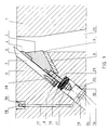
- In the following, the invention is described by the aid of an example by referring to the attached drawings, in which
- Fig. 1
- presents a partial cross-section through the chipper disc of the invention, showing the region of a knife,
- Fig. 2
- presents a corresponding cross-section of another embodiment of the invention,
- Fig. 3
- presents a corresponding cross-section of a third embodiment of the invention.
- In front view, the
disc 1 of a disc chipper is a round plate rotating about an essentially horizontal center axis. As shown in Fig. 1, placed at the level of each knife, thedisc 1 of a disc chipper has a radial or nearlyradial knife aperture 20 through which the chips produced during chipping are removed for further treatment. In connection with each knife aperture on the log feed side of the disc is a knife holding slot consisting ofsurfaces bottom 8 of the slot. In the embodiment illustrated by Fig. 1, this slot is a cut-out in the disc itself, whereas in the embodiment in Fig. 2 the knife holding slot is incorporated in a separate wearing plate attached to the disc. Theknife 3 is a body of a narrow, elongated shape and a length nearly equal to that of theknife aperture 20. In the drawings, the knife is depicted in cross-section. The rear surface of the knife rests against thefirst wedge surface 7 of the knife slot, and its lower end rests against thebottom 8 the knife slot, either directly or viaadjustment screws 28. The rear surface of the knife is defined as the hindmost one of the flat surfaces of the knife as seen in the direction of rotation of thedisc 1. Correspondingly, the other flat surface is the front surface of the knife. A disc usually has 12 knives mounted at even distances in a radial or nearly radial arrangement, but the number of knives may also be other than 12, e.g. 16. - In addition to the knife itself, the knife slot accommodates a
knife holder 2, which is of a length essentially corresponding to that of the knife. In cross-sectional form, the knife holder is a wedge-shaped body tapering towards the bottom of the knife slot. The rear surface of the knife holder rests against the front surface of the knife, either directly or via aconnectors other wedge surface 9 of the knife slot, either directly or via aconnector 5. Since the knife is a body of uniform thickness, the wedge angles of the knife slot andknife holder 2 must correspond to each other, unless such correspondence is ensured by using additional wedge-shaped connectors. - As shown particularly in Fig. 1 and 3, the
knife holder 2 used in the solutions of the invention has a small wedge angle. This provides the advantage of rendering the wedge-shaped knife holder 2 completely or at least partially self-retaining. Because of its small wedge angle, the knife holder has a structure that enables most of the forces received by it from the knife during chipping to be transmitted directly through the knife holder to its opposite side, where the friction causes the forces to be transmitted to thedisc 1. Therefore, the only function of the knife fixing elements is to perform the fastening movement when the knife is replaced and to ensure that the knife holder remains in place when the chipper is in operation. By considering the forces transmitted from the log being chipped to the knife and further to the guide surfaces, it is possible to calculate the wedge angle value required for the knife holder to be self-retaining at a given friction coefficient value. When the surfaces are made of steel, a suitable friction coefficient value is between 0.2 - 0.3, depending on lubrication. By placing these values in the equation for wedge angle, it will be seen that the required wedge angle is between 11.3° - 16.7°. In practice, however, it is not advisable to use wedge angles as small as this, since part of the forces produced during chipping can be received by the fixing elements. Thus, a preferable knife holder wedge angle is between 15° - 25°. - The bottom side of the
knife holder 2 is provided with threaded holes arranged in a straight row essentially over the whole length of the knife holder. Fitted in each threaded hole is a tighteningpin 29 provided with a threaded part of suitable length at each end. Thedisc 1 or the separate wearingplate 21 is provided with borings corresponding to the threaded pins, said borings being of a size permitting the shanks of the threaded pins to move in them. Each boring is followed by a larger cut-out 26 in thedisc 1 or the wearingplate 21, which may have a round, rectangular or other suitable crossectional form. In the embodiments illustrated, the cut-out 26 is of a circular cross-section and concentric with the boring made for the tightening pin. The cut-out 26 opens in a direction away from the knife, either in the widthwise direction of the knife or in some other suitable direction. In the chippers represented by Fig. 1 and 3, the cut-out opens to the side opposite to the knife, i.e. to the backside of the disc. In these cases, the cut-out continues to the backside of the disc without any change in its dimensions and direction. By contrast, in the chipper illustrated by Fig. 2, the cut-out continues for some distance from the knife without any change in its dimensions and direction, but it then widens out in the longitudinal direction of the knife into atransverse cavity 30 extending nearly over the whole length of the knife and interconnecting all the collateral cut-outs 26. - At the end of the cut-out 26 facing towards the knife is a set of
springs 10 acting as a knife fixing element, preferably consisting of a number of successive cup springs. By means of tightening andadjustment nuts 11 andsuitable spacers 25, the set ofsprings 10 is so placed around the tighteningpin 29 that thesprings 10 are compressed between the cut-out end facing the knife and theadjustment nuts 11 orspacers 25, producing a pressing force which is transmitted via the tightening pin to theknife holder 2 so as to pull it in the direction of the pin. As a result, due to the mutually corresponding wedge-like shapes of theknife holder 2 and knife slot, theknife 3 is firmly pressed in position. The wedge angles and the direction of the tightening motion are so chosen that when the nuts 11 are being tightened theknife holder 2 will simultaneously press theknife 3 firmly against the bottom of theknife slot 8. Thus, the force of the springs holds the knife securely in position in the disc and the knife remains immobile after it has been mounted. - In the chippers shown in Fig. 1 and Fig. 3 , the free end of the cut-out constitutes a cylinder with a
movable piston 12 inside it. The piston is used for releasing the knives. The piston is provided withseals 13 to seal the gap between the cut-out and the sliding surface of the piston. Furthermore, the free end of the cut-out is provided with abackplate 15 locked in place by means of threads to close the cut-out end tightly. Attached to the backplate is astopper pin 14 extending from the backplate into thepiston 12, permitting the latter to move in the cut-out through a limited distance. The travel of the piston is so adjusted that the stopper pin will stop the piston after the latter has reached the end of the tighteningpin 29 and pushed theknife holder 2 clear of the knife. In this way, the piston is prevented from completely flattening thesprings 10. The part of the cut-out between thepiston 12 and thebackplate 15 forms acircular pressure space 16. This space communicates with apressure channel 17, which may run from the front side of the disc as in Fig. 1, or equally well from the backside or the circumference of the disc. These solutions depend on the embodiment used in each case. The starting end of the pressure channel is provided with a quick-disconnect fitting 18 placed in a cut-out 19 in the disc to protect it against damage. The other end of the pressure channel branches out into all of the collateral cut-outs 26 so that the pressure fed in through the quick-disconnect fitting 18 acts with equal force in all of them. The pressure system may be hydraulic or pneumatic, so the pressure medium used depends on the system. - In the system illustrated by Fig. 2, there is a slight structural difference as comapared to the systems in Fig. 1 and 3. In this case, the
transverse cavity 30 accommodates ahose 22 made of an elastic material and used as a means of releasing the knives. The bearing surfaces for the hose consist of abackplate 24 placed behind the hose and asupport plate 23 placed between the hose and the tighteningpin 29. A pressure is fed into the hose via a quick-disconnect fitting as described above. In addition, the wearingplate 21 is provided with a bearingelement 27 placed at the knife-holding end of the plate. - When the knives are to be replaced, a pressure, e.g. hydraulic pressure, is connected to the system via the quick-
disconnect fitting 18. This causes thepiston 12 orhose 22 to move within a limited travel towards the tighteningpin 29, pressing it against the spring force. Theknife holder 2 now moves in the same direction with the tightening pin, releasing the knife. The worn-out knife is removed from its slot and a new one is inserted, whereupon the extra pressure is let out from the system. The depressurization is not described separately, but it may occur via the same quick-disconnect fitting 18 through which the pressure is fed into the system. When the pressure is removed from the system, the set ofsprings 10 pulls theknife holder 2 back to its tightening position and pushes thepiston 12 orhose 22 back to its original position. Thus, the knife has been firmly secured and another one can be replaced. - In a chipper constructed as shown in Fig. 2, it is possible to use a mechanical wabbler shaft instead of a
hose 22 and a pressure system. In this case, a shaft provided with eccentric cams is mounted in place of thehose 22 and one end of the shaft is provided with a nut or other suitable element by which the shaft can be rotated with a sufficient power. When the shaft is rotated, the eccentric cams act against the spring force, thereby releasing the knife. After the knife has been replaced, the wabbler shaft is turned back to a position where the eccentric cams are disengaged from contact with the tightening pin or equivalent and the springs cause the knife to be tightened in position. - It is obvious to a person skilled in the art that the invention is not restricted to the examples described above, but that it may be infinitely varied within the scope of the following claims.
Claims (3)
- Procedure for replacing a knife in a chipper which rotates about its center axis and on which several knifes (3) are fixed by means of knife holders (2) and knife fixing elements (10), said knives being replaced by applying a force to one or more releasing devices (12,22) mounted inside the chipper, in such a way that the respective releasing device acts on the fixing element (10) of a knife in a direction essentially opposite to the direction of the retaining force generated by the knife fixing element (10), causing the grip of the knife holder (2) to be loosened, and the knife (3) is removed from its place and a new knife is inserted into the place thus vacated, and the releasing device being deactivated,
characterized in that- in a disk chipper provided with a disk (1), on which the knives (3) are arranged radially or nearly radially and are fixed along their length by means of several fixing elements (10);- the force which holds the knife in position is directed inwards that, due to friction, the fixing motion pulls the knife (3) against the bottom (8) of the knife slot (7) in the disk (1), and- for replacing a knife (3) the releasing device (12,22) acts on all the fixing elements (10) of one knife (3) essentially simultaneously, in such a way that that side of the releasing device which lies closer to the knife fixing element (10) is pushed towards each knife fixing element (10). - Apparatus for replacing a knife in a disk chipper provided with a disk (1), which rotates about its center axis and on which, in connection with chip apertures (20), several knife holding slots (7-9) are arranged radially or nearly radially and tapering in a wedge-like manner towards the bottom (8) of the slot, said slots accomodating a knife (3) of a narrow elongated shape and a knife holder (2) with a corresponding wedge-shaped body tapering towards the bottom of the knife slot, several knife fixing elements (10) pulling the knife holder (2) inwards that, due to friction, the fixing motion pulls the knife (3) against the bottom (8) of the slot (7) in the disk, the disk further being provided with cut-outs (26) for releasing devices (12,22) acting on the fixing elements (10), and at least one actuator acting on the releasing devices in such a way that the releasing devices, when activated, act on the knife fixing elements (10) of one knife essentially simultaneously, causing the knife (3) to be loosened.
- Apparatus according to claim 2,
characterized in that
the releasing device (12) is a piston mounted in the cut-out (26) and so moving in it due to a pressure applied to it that, actuated by the pressure, the piston is pressed against the spring force of the fixing elements (10).
Applications Claiming Priority (2)
| Application Number | Priority Date | Filing Date | Title |
|---|---|---|---|
| FI903733 | 1990-07-26 | ||
| FI903733A FI87159C (en) | 1990-07-26 | 1990-07-26 | FOLLOWING ORGANIZATION FOR THE PURPOSE OF THE KNOWLEDGE I AND SKIVHUGG |
Publications (2)
| Publication Number | Publication Date |
|---|---|
| EP0468458A1 EP0468458A1 (en) | 1992-01-29 |
| EP0468458B1 true EP0468458B1 (en) | 1994-11-30 |
Family
ID=8530841
Family Applications (1)
| Application Number | Title | Priority Date | Filing Date |
|---|---|---|---|
| EP91112347A Expired - Lifetime EP0468458B1 (en) | 1990-07-26 | 1991-07-23 | Procedure and apparatus for replacing a knife in a disc chipper |
Country Status (4)
| Country | Link |
|---|---|
| EP (1) | EP0468458B1 (en) |
| CA (1) | CA2047789A1 (en) |
| DE (2) | DE69105389T2 (en) |
| FI (1) | FI87159C (en) |
Families Citing this family (4)
| Publication number | Priority date | Publication date | Assignee | Title |
|---|---|---|---|---|
| FI90322C (en) * | 1992-11-18 | 1994-01-25 | Andritz Patentverwaltung | Method and apparatus for replacing a disc retrieval blade |
| FR2783725B1 (en) * | 1998-09-28 | 2000-12-15 | Dimetal | MACHINE FOR FRAGMENTING BLOCKS OF NATURAL OR SYNTHETIC ORGANIC MATERIAL, SUCH AS WOOD |
| FI20021248A0 (en) | 2002-06-26 | 2002-06-26 | Metso Paper Inc | Procedure for squeezing bites |
| DE102004058491A1 (en) * | 2004-12-04 | 2006-06-14 | Sms Demag Ag | Device for clamping a knife in scissors for cutting strips |
Family Cites Families (6)
| Publication number | Priority date | Publication date | Assignee | Title |
|---|---|---|---|---|
| US3014511A (en) * | 1959-03-12 | 1961-12-26 | Kirsten Paul Arthur | Rotary tool for woodworking and woodcutting machines |
| DE1154613B (en) * | 1961-01-04 | 1963-09-19 | Hombak Maschinenfab Kg | Knife shaft for wood cutting machines |
| DE1653094A1 (en) * | 1967-01-31 | 1971-09-16 | Hombak Maschinenfab Kg | Device for relieving spring-loaded tensioning wedges on cutting tools |
| AR202696A1 (en) * | 1972-09-08 | 1975-07-15 | Koester H | DEVICE FOR THE PLACEMENT OF CHIP STARTER KNIVES, WITH MEASUREMENT PRECISION REGARDING THEIR WORKING ANGLE |
| FR2229516A1 (en) * | 1973-05-18 | 1974-12-13 | Duffour Gilbert | Rotary wood cutting tool - radial blades trapped between circumferential segments, released hydraulically |
| DE2405000A1 (en) * | 1974-02-02 | 1975-08-07 | Hombak Maschinenfab Kg | Cutter clamp for woodworking tool - has pressure piston with oil circuit and stronger spring for second stage |
-
1990
- 1990-07-26 FI FI903733A patent/FI87159C/en active IP Right Grant
-
1991
- 1991-07-23 DE DE69105389T patent/DE69105389T2/en not_active Expired - Fee Related
- 1991-07-23 DE DE199191112347T patent/DE468458T1/en active Pending
- 1991-07-23 EP EP91112347A patent/EP0468458B1/en not_active Expired - Lifetime
- 1991-07-24 CA CA002047789A patent/CA2047789A1/en not_active Abandoned
Also Published As
| Publication number | Publication date |
|---|---|
| DE69105389D1 (en) | 1995-01-12 |
| FI87159C (en) | 1992-12-10 |
| DE468458T1 (en) | 1992-05-21 |
| EP0468458A1 (en) | 1992-01-29 |
| DE69105389T2 (en) | 1995-04-20 |
| FI903733A0 (en) | 1990-07-26 |
| FI87159B (en) | 1992-08-31 |
| FI903733L (en) | 1992-01-27 |
| CA2047789A1 (en) | 1992-01-27 |
Similar Documents
| Publication | Publication Date | Title |
|---|---|---|
| CA2255427C (en) | Pivoting knife clamp | |
| US5485873A (en) | Knife clamping system | |
| CA1229970A (en) | Cutting tool with removable blades | |
| EP0325577A1 (en) | ROTATING KNIFE HEADS. | |
| US4370908A (en) | Cutting head for filter assembler | |
| US4685497A (en) | Knife arrangement for a waferizer | |
| US5444904A (en) | Device for replacing the knives of a disc chipper | |
| EP0468458A1 (en) | Procedure and apparatus for replacing a knife in a disc chipper | |
| US6848640B2 (en) | Device for comminuting material and knife support plate | |
| EP1510308B1 (en) | Knife assembly | |
| EP1568453B1 (en) | Ring slicer with easily removable knife and knife assembly | |
| US7293730B2 (en) | Knife fixing method | |
| WO2007081892A1 (en) | Method and apparatus for adjusting knife extension | |
| US2997146A (en) | Automatic brake for winches and the like | |
| US7584772B2 (en) | Method for clamping a knife in a disc chipper and a knife clamp for a knife assembly | |
| CA1052991A (en) | Wood chipping tool | |
| JP3237666B2 (en) | Roll and roll assembly method | |
| CN209977098U (en) | Hydraulic braking clamp | |
| US5070785A (en) | Device for tensioning printing plates mounted on a cylinder of an intaglio printing machine | |
| CN220590267U (en) | Breaker of breaker | |
| RU2344927C2 (en) | Shears knife clamping fixture for crosswise band separation | |
| CA2560515C (en) | Ring slicer with easily removable knife and knife assembly | |
| SU827331A1 (en) | Engraving device | |
| CA2501622C (en) | Ring slicer with easily removable knife and knife assembly | |
| KR200301279Y1 (en) | A side trimmer having a knife to mouted the same ealily |
Legal Events
| Date | Code | Title | Description |
|---|---|---|---|
| PUAI | Public reference made under article 153(3) epc to a published international application that has entered the european phase |
Free format text: ORIGINAL CODE: 0009012 |
|
| AK | Designated contracting states |
Kind code of ref document: A1 Designated state(s): DE SE |
|
| 17P | Request for examination filed |
Effective date: 19920324 |
|
| DET | De: translation of patent claims | ||
| 17Q | First examination report despatched |
Effective date: 19930512 |
|
| GRAA | (expected) grant |
Free format text: ORIGINAL CODE: 0009210 |
|
| RAP1 | Party data changed (applicant data changed or rights of an application transferred) |
Owner name: KONE WOOD OY |
|
| AK | Designated contracting states |
Kind code of ref document: B1 Designated state(s): DE SE |
|
| REF | Corresponds to: |
Ref document number: 69105389 Country of ref document: DE Date of ref document: 19950112 |
|
| RAP2 | Party data changed (patent owner data changed or rights of a patent transferred) |
Owner name: ANDRITZ-PATENTVERWALTUNGS-GESELLSCHAFT M.B.H. |
|
| PLBE | No opposition filed within time limit |
Free format text: ORIGINAL CODE: 0009261 |
|
| STAA | Information on the status of an ep patent application or granted ep patent |
Free format text: STATUS: NO OPPOSITION FILED WITHIN TIME LIMIT |
|
| 26N | No opposition filed | ||
| PGFP | Annual fee paid to national office [announced via postgrant information from national office to epo] |
Ref country code: SE Payment date: 20080618 Year of fee payment: 18 Ref country code: DE Payment date: 20080623 Year of fee payment: 18 |
|
| EUG | Se: european patent has lapsed | ||
| PG25 | Lapsed in a contracting state [announced via postgrant information from national office to epo] |
Ref country code: DE Free format text: LAPSE BECAUSE OF NON-PAYMENT OF DUE FEES Effective date: 20100202 |
|
| PG25 | Lapsed in a contracting state [announced via postgrant information from national office to epo] |
Ref country code: SE Free format text: LAPSE BECAUSE OF NON-PAYMENT OF DUE FEES Effective date: 20090724 |