EP0468415B1 - Magnet assembly - Google Patents
Magnet assembly Download PDFInfo
- Publication number
- EP0468415B1 EP0468415B1 EP91112259A EP91112259A EP0468415B1 EP 0468415 B1 EP0468415 B1 EP 0468415B1 EP 91112259 A EP91112259 A EP 91112259A EP 91112259 A EP91112259 A EP 91112259A EP 0468415 B1 EP0468415 B1 EP 0468415B1
- Authority
- EP
- European Patent Office
- Prior art keywords
- magnet assembly
- assembly
- ring
- magnetic field
- magnet
- Prior art date
- Legal status (The legal status is an assumption and is not a legal conclusion. Google has not performed a legal analysis and makes no representation as to the accuracy of the status listed.)
- Expired - Lifetime
Links
- 230000005291 magnetic effect Effects 0.000 claims description 61
- 238000010791 quenching Methods 0.000 claims description 30
- 239000001307 helium Substances 0.000 claims description 23
- 229910052734 helium Inorganic materials 0.000 claims description 23
- SWQJXJOGLNCZEY-UHFFFAOYSA-N helium atom Chemical compound [He] SWQJXJOGLNCZEY-UHFFFAOYSA-N 0.000 claims description 23
- 230000005855 radiation Effects 0.000 claims description 16
- 239000004411 aluminium Substances 0.000 claims description 12
- 229910052782 aluminium Inorganic materials 0.000 claims description 12
- XAGFODPZIPBFFR-UHFFFAOYSA-N aluminium Chemical compound [Al] XAGFODPZIPBFFR-UHFFFAOYSA-N 0.000 claims description 12
- 239000000463 material Substances 0.000 claims description 11
- 230000000712 assembly Effects 0.000 claims description 6
- 238000000429 assembly Methods 0.000 claims description 6
- RYGMFSIKBFXOCR-UHFFFAOYSA-N Copper Chemical compound [Cu] RYGMFSIKBFXOCR-UHFFFAOYSA-N 0.000 claims description 5
- 229910052802 copper Inorganic materials 0.000 claims description 5
- 239000010949 copper Substances 0.000 claims description 5
- IJGRMHOSHXDMSA-UHFFFAOYSA-N Atomic nitrogen Chemical compound N#N IJGRMHOSHXDMSA-UHFFFAOYSA-N 0.000 description 8
- 230000000694 effects Effects 0.000 description 8
- 238000004364 calculation method Methods 0.000 description 7
- 230000004907 flux Effects 0.000 description 7
- 230000008878 coupling Effects 0.000 description 6
- 238000010168 coupling process Methods 0.000 description 6
- 238000005859 coupling reaction Methods 0.000 description 6
- 239000007788 liquid Substances 0.000 description 6
- 238000004458 analytical method Methods 0.000 description 5
- 238000000034 method Methods 0.000 description 5
- 239000004020 conductor Substances 0.000 description 4
- 238000009826 distribution Methods 0.000 description 4
- 229910052757 nitrogen Inorganic materials 0.000 description 4
- 239000010935 stainless steel Substances 0.000 description 4
- 229910001220 stainless steel Inorganic materials 0.000 description 4
- 230000001052 transient effect Effects 0.000 description 4
- 238000004804 winding Methods 0.000 description 4
- 239000004593 Epoxy Substances 0.000 description 3
- QVGXLLKOCUKJST-UHFFFAOYSA-N atomic oxygen Chemical compound [O] QVGXLLKOCUKJST-UHFFFAOYSA-N 0.000 description 3
- 238000001816 cooling Methods 0.000 description 3
- 230000000977 initiatory effect Effects 0.000 description 3
- 239000001301 oxygen Substances 0.000 description 3
- 229910052760 oxygen Inorganic materials 0.000 description 3
- 238000005481 NMR spectroscopy Methods 0.000 description 2
- 239000000956 alloy Substances 0.000 description 2
- 229910045601 alloy Inorganic materials 0.000 description 2
- 230000004323 axial length Effects 0.000 description 2
- 238000009835 boiling Methods 0.000 description 2
- 230000008859 change Effects 0.000 description 2
- 238000004590 computer program Methods 0.000 description 2
- 238000010276 construction Methods 0.000 description 2
- 238000010586 diagram Methods 0.000 description 2
- 239000007789 gas Substances 0.000 description 2
- 239000000203 mixture Substances 0.000 description 2
- 230000008569 process Effects 0.000 description 2
- 230000000171 quenching effect Effects 0.000 description 2
- 239000002887 superconductor Substances 0.000 description 2
- 230000007812 deficiency Effects 0.000 description 1
- 238000010292 electrical insulation Methods 0.000 description 1
- 239000000284 extract Substances 0.000 description 1
- 239000011152 fibreglass Substances 0.000 description 1
- 230000014509 gene expression Effects 0.000 description 1
- 238000003384 imaging method Methods 0.000 description 1
- 230000006698 induction Effects 0.000 description 1
- 238000005304 joining Methods 0.000 description 1
- 238000004519 manufacturing process Methods 0.000 description 1
- 239000011159 matrix material Substances 0.000 description 1
- 229910052751 metal Inorganic materials 0.000 description 1
- 239000002184 metal Substances 0.000 description 1
- 150000002739 metals Chemical class 0.000 description 1
- 230000035699 permeability Effects 0.000 description 1
- 238000004088 simulation Methods 0.000 description 1
- 230000036962 time dependent Effects 0.000 description 1
- 230000007704 transition Effects 0.000 description 1
Images


Classifications
-
- G—PHYSICS
- G01—MEASURING; TESTING
- G01R—MEASURING ELECTRIC VARIABLES; MEASURING MAGNETIC VARIABLES
- G01R33/00—Arrangements or instruments for measuring magnetic variables
- G01R33/20—Arrangements or instruments for measuring magnetic variables involving magnetic resonance
- G01R33/28—Details of apparatus provided for in groups G01R33/44 - G01R33/64
- G01R33/42—Screening
- G01R33/421—Screening of main or gradient magnetic field
-
- G—PHYSICS
- G01—MEASURING; TESTING
- G01R—MEASURING ELECTRIC VARIABLES; MEASURING MAGNETIC VARIABLES
- G01R33/00—Arrangements or instruments for measuring magnetic variables
- G01R33/20—Arrangements or instruments for measuring magnetic variables involving magnetic resonance
- G01R33/28—Details of apparatus provided for in groups G01R33/44 - G01R33/64
- G01R33/38—Systems for generation, homogenisation or stabilisation of the main or gradient magnetic field
- G01R33/381—Systems for generation, homogenisation or stabilisation of the main or gradient magnetic field using electromagnets
- G01R33/3815—Systems for generation, homogenisation or stabilisation of the main or gradient magnetic field using electromagnets with superconducting coils, e.g. power supply therefor
-
- Y—GENERAL TAGGING OF NEW TECHNOLOGICAL DEVELOPMENTS; GENERAL TAGGING OF CROSS-SECTIONAL TECHNOLOGIES SPANNING OVER SEVERAL SECTIONS OF THE IPC; TECHNICAL SUBJECTS COVERED BY FORMER USPC CROSS-REFERENCE ART COLLECTIONS [XRACs] AND DIGESTS
- Y10—TECHNICAL SUBJECTS COVERED BY FORMER USPC
- Y10S—TECHNICAL SUBJECTS COVERED BY FORMER USPC CROSS-REFERENCE ART COLLECTIONS [XRACs] AND DIGESTS
- Y10S505/00—Superconductor technology: apparatus, material, process
- Y10S505/70—High TC, above 30 k, superconducting device, article, or structured stock
- Y10S505/704—Wire, fiber, or cable
- Y10S505/705—Magnetic coil
Definitions
- the invention relates to a cylindrical magnet assembly comprising a first superconducting coil assembly A-D coaxial with the cylinder axis of said cylindrical assembly for generating a first magnetic field and being located within at least one radiation shield 17, a second superconducting coil assembly E-F' coaxial with said cylinder axis for generating a second magnetic field and being located within said at least one radiation shield 17, the second superconducting coil assembly E-F' being electrically connected in series with the first superconducting coil assembly A-D, wherein the first and second superconducting coil assemblies A-D, E-F' each generate, in use, magnetic fields whose corresponding components are of the same order of magnitude, the assemblies being arranged such that a resultant, uniform magnetic field is generated in a working volume, and the second magnetic field opposes the first magnetic field externally of the magnet assembly, whereby the resultant magnetic field prevailing externally of the magnet assembly is maintained within preset limits during normal operation of the assembly in which the current in the superconducting coils is constant.
- An active-shield assembly is one in which an inner coil system and an outer coil system are connected in series to create magnetic fields in opposing directions so that a strong uniform magnetic field is created at the centre of the coil system but the stray field prevailing outside the coil systems is very small.
- a coil in a superconducting state can convert to a normal conducting state, the transition being commonly referred to as a quench.
- a quench may occur unintentionally, due to local disturbances or structural deficiencies or it can be induced intentionally (for example, by means of local electrical heaters) as a way of rapidly reducing the magnetic fields. This might be needed for example in a case where it is necessary to give urgent treatment to a patient undergoing an NMR procedure in the magnet assembly.
- a quench occurs, there is a rapid increase in resistance in the quenched part of the coil which causes the energy stored in the coil system to be converted into heat. The heat is conducted to adjacent parts of the coil, causing these parts to quench.
- the temperature associated with the heat energy increases, causing the resistance of the coil to rise further and accelerating the quench process until all the stored magnetic energy is converted into heat. This can occur extremely quickly, typically in about 10 to 20 seconds.
- the increased resistance in the coils causes the current carried by the coils to decay. As the current in the coils decays, the magnetic field provided by the coils alters rapidly.
- the magnets are wound onto formers which are generally of aluminium, and the coils are housed within radiation shielding casings which are suspended in a cryostat housing.
- the casings and housing are formed of a material having a high thermal conductivity such as aluminium and tend also as a result to have a high electrical conductivity.
- the altering magnetic field couples with the electrically conductive components in the magnet assembly and cryostat structure. In particular, it couples strongly with the formers on which the coils are wound, and the radiation shielding casings within the cryostat. This magnetic coupling induces currents in these components, which currents are sufficiently large to generate significant magnetic fields.
- the coils of an active-shield magnet assembly are designed not only to produce a uniform magnetic field at the centre of the assembly but also to produce an external magnetic field which is as low as possible as close as possible to the assembly.
- the external magnetic field is termed herein the "stray field” and is commonly specified in terms of an ellipsoidal or cylindrical volume outside which the magnetic field due to the magnet assembly nowhere exceeds a specified level. This provides a way of denoting a safety zone a certain distance from the magnet.
- the other components of the magnet assembly are designed according to thermal and structural considerations, so that the distribution of currents induced in them during a quench is uncontrolled. In normal circumstances this is not a problem, since no currents flow in these components during the steady state operating condition.
- significant, uncontrolled currents can be induced as explained above.
- the magnetic field created by the induced currents upsets the balance between the central magnetic coils and the shielding magnetic coils.
- the result can be a temporary but significant increase in the stray field during a quench, which could present a risk to people or equipment located in the "safety zone" close to the positions for which a steady maximum stray field value is specified under normal circumstances. This is clearly undesirable, particularly in hospitals where sensitive equipment might be located in the nominal safety zone.
- the assembly further includes at least one ring 10, 10', 11, 11' formed of an electrically conductive, non-superconducting material and disposed on or within said at least one radiation shield 17 and being coaxial with said cylinder axis, the ring being so sized and positioned that the current induced in the ring during a quench of the superconducting magnet creates a magnetic field which acts to oppose the magnetic fields created by the currents induced in conductive parts of the magnet assembly so that the resultant magnetic field prevailing externally of the magnet assembly remains within said preset limit for normal operation.
- the ring can take the form of a conductive hoop, band or coil, and there can be several such rings so sized and positioned that their combined magnetic effect during a quench maintains the external field within the preset limits.
- the rings can be mounted on any convenient cylindrical surface.
- the ring(s) can be located around either or both of the first and second formers and supported thereby. Where the superconducting coils are housed within radiation shielding casings, the ring or rings may be mounted on these casings. To achieve the required low temperatures for superconductivity, the first and second formers can be housed in a helium container, itself surrounded by a vacuum chamber. The rings could then be mounted on either the helium container or the vacuum chamber.
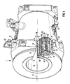
- FIG. 1 illustrates in partly cut away form a magnet assembly 1.
- the magnet assembly 1 comprises an inner, cylindrical former 2 made of stainless steel defining the working volume of the magnet assembly constituted by a bore 3 having an axis 4.
- a cylindrical, aluminium former 5 Positioned radially outwardly of the former 2 is a cylindrical, aluminium former 5 coaxial with the axis 4.
- the former 5 carries three pairs of coils A, A', B, B', C, C' arranged symmetrically about a mid-plane 6 (see Figure 2) of the assembly normal to the axis 5 and a seventh coil D arranged symmetrically astride the mid-plane 6. These coils can be seen from Figure 2.
- Each of the coils A - D is formed from a superconductive conducting material for example comprising fine strands of alloy Type TI superconductor, a matrix of good normal conductor in which the superconductor strands are embedded in the form of a regular array, and a surface electrical insulation to cope with energisation and fault mode voltages.
- Each of the coils A - D is wound separately.
- the coils are embedded in a wax or epoxy composition and may be surrounded by a clamping ring (not shown).
- each pair of coils is positioned between respective pairs of annular ribs 5A, 5B etc. of the former 5.
- the purpose of the wax or epoxy composition and the ribs is to prevent movement of the windings of the coil in use to try and prevent any small movements which might be accompanied by the generation of a small amount of heat which could lead to quenching.
- the former 5 In view of the close spacing of the coils A - D, the former 5 must be constructed to accommodate large forces between adjacent coils which, in the axial direction, can amount to some 2 000 000 N (200,000 Kgf). In addition, the former 5 must be as light as possible to reduce the overall weight of the magnet assembly and be as near to a right cylinder as possible.
- a second, aluminium former 7 is mounted radially outwardly of the former 5.
- the former 7 carries four shielding coils E, E' - F, F' (see Figure 2) arranged symmetrically about the mid-plane 6 of the magnet assembly in a manner to be described below.
- the coils E-F' are mounted between respective pairs of ribs 7E, 7F of the former 7 in a way similar to the coils A-D.
- Clamping rings (not shown) and wax or epoxy are used to reduce movement of the coil windings as described above in relation to the former 5.
- a helium can defined by an outer cylindrical wall 8 and an inner cylindrical wall 9.
- the helium can is closed by a pair of ring members 12.
- the walls 8, 9 and ring members 12 are all made of stainless steel.
- Liquid helium is supplied to a helium can via an inlet 13 mounted in a turret 14.
- the helium can could alternatively be made of a material having a higher conductivity than that of stainless steel, for example aluminium.
- Cylindrical, aluminium radiation shields 15, 15' are mounted coaxially, radially outwardly and inwardly respectively about the helium can to define an evacuated space 16 between the shields 15, 15' and the helium can.
- the shields 15, 15' are cooled by contact with helium through the agency of a heat exchanger (not shown) in the turret 14 which extracts heat from the radiation shields 15, 15' and passes it to the cold helium gas that has been boiled from the helium can.
- Further cooling of the shields to achieve a lower temperature may be achieved by a second heat exchanger connected to the second stage of a closed-cycle Gifford-McMahon refrigerator.
- FIG. 1 Further aluminium radiation shields 17, 17' are mounted coaxially, radially outwardly and inwardly respectively about the shields 15, 15' to define an evacuated space 18.
- liquid nitrogen is supplied to an annular tank 26 of which the shield 17 forms the skin.
- These shields may be connected through a heat exchanger to the first stage of a 2-stage closed cycle Gifford-McMahon refrigerator which has sufficient cooling power to reduce or eliminate the boil off of nitrogen from the tank.
- a cylindrical stainless steel outer casing 20 is mounted coaxially about the shield 17 to define a vacuum space 21.
- the outer casing 20 could alternatively be formed of aluminium. Pairs of aluminium end plates 22,23,24 (see Figure 2) are provided to close the ends of the spaces 16,18,21.
- the various shields are supported by a system of glass reinforced plastic rods (not shown) mounted in corresponding attachment plates. These rods when configured as a three dimensional array of struts will support a 4000 kilogram magnet at the expense of a heat leak of no more than 0.04 watts.
- the helium can 8,9 is filled with liquid helium which will be at 4.21K.
- the gas produced will pass into the heat exchanger in the turret 14 which will cool the shields 15, 15' to a temperature of about 40K (referred to as the 40K heat shield).
- the boiling of the liquid helium maintains the wall of the helium can at 4.2K.
- Liquid nitrogen being present in the tank maintains the shields 17, 17' at a temperature of about 77K (referred to as the 80K heat shield).
- the spaces 16,18,21 are connected through a valve 27 to the atmosphere to enable the spaces to be evacuated.
- the nitrogen tank 26 may be omitted when the shields 15,17 are cooled by a 2 stage Gifford-McMahon closed cycle refrigerator.
- the coils A-F' are all connected in series with each other so that the same current flows in each.
- the coils are connected in a closed circuit with a switch 30.
- a protection circuit 32 is connected across the switch 30.
- the invention provides in the described embodiment a set of rings of conductive material sized and placed so that the current induced in the rings in a transient condition creates a magnetic field which acts in substantial opposition to the magnetic field created by the current induced in the formers, thereby to prevent the stray field exceeding preset limits.
- four rings 10,10',11,11' are located respectively radially outwardly of the coils C,C' and E,E'.
- the rings are manufactured from high conductivity oxygen free copper with a residual resistivity ratio of approximately 70.
- the residual resistivity ratio is the ratio of the resistivity at 300K to the resistivity at 4.2K. They are located coaxially with the coils using dowel pins to prevent movement when large forces are present during a quench.
- the size and position of the ring(s) can be calculated according to the following.
- the transient condition of most concern is a quench, either intentionally or unintentionally produced.
- a quench In order to calculate the design parameters of the rings it is first necessary to know approximately the time-dependent variation in the coil current as the quench proceeds. This can be determined experimentally, by observing the change in central magnetic field during a quench, or more conveniently by simulation using a suitable computer program.
- cryostat, magnet formers 5,7 and coils A-F' are modelled as an axisymmetric construction with the initial coil current set to its normal steady value. That is, the symmetry of the assembly is such that the system can be represented by a 1/4-section, defined by the axes OX, OZ. This 1/4-section is used as the basis for these calculations.
- the analysis proceeds step-by-step, calculating the distribution of current in all the conductive elements at pre-determined time intervals, and the corresponding values of magnetic field throughout the whole of space.
- the result of such a calculation is shown in Figure 5.
- the contour 31 in Figure 5 joins the places where the modulus of magnetic flux density B mod is 0.5mT when the magnet is energised to a steady field of 1.0T at the centre O.
- the contours 32-36 show where the same 0.5mT flux density is expected to be at intervals of 3 seconds in numerical order after the initiation of a quench when the rings 10-11' are not fitted to the magnet assembly.
- the contour 37 shows where the flux density is 0.1mT 15 seconds after the initiation of the quench.
- a first estimate of the size and position of the ring(s) can be determined using the following steps.
- the magnetic dipole moment m f is estimated by superimposing a surface of shape given by Equation (1) onto a map of contours of magnetic flux density B mod produced from the calculation, as shown in Figure 5.
- the best fit to a constant value of B mod over this surface is then obtained after extracting the contribution of the magnet coils themselves. This can be done most conveniently at time intervals approaching t o ( Figure 4), denoting the end of the quench, at which point the contribution of the magnetic coils to the magnet field is small but the contribution of the current induced in the formers I f is still significant.
- the value of r thus obtained at selected value of B mod is substituted in Equation (2) to give the equivalent magnetic dipole moment.
- This calculation can be repeated at many intervals during the quenching progess to determine how the magnetic dipole moment m varies with time due to the different time-constants of different parts of the system. It is particularly useful to derive the time constant for decay of current in the formers after termination of the quench (t o -t 1 ) and the worst case of stray field, which occurs around the time t 2 when currents in both the formers 5,7 and the coils A-F' are contributing to the stray field.
- the object of the invention is to have a total magnetic dipole moment m as close to zero as possible.
- the principle of the invention is to generate by induction in a ring or rings an equal and opposite magnetic dipole moment to that calculated in step 1.
- the ring it is preferable to design the ring to have a simple cross-section of limited area so that a uniform current density within the ring is a reasonable approximation. Also for a first estimate the currents induced in the formers 5,7 and shields 15,15',17',17, (and helium can and outer casing if made of a conductive material) can be ignored for the purpose of calculating the coupling to the rings as they are much less significant than the decaying current Im in the magnet coils.
- equation (3) For the general case where I m is not a simple function of time, equation (3) must be solved numerically. However, for a first approximation I m can be assumed to have the form of an exponential decay in the area of importance. This can be seen from Figure 4, where t 3 indicates the beginning of the zone of importance.
- I m I o ⁇ e -t/ ⁇ m
- ⁇ m is a decay time constant determined from the curve of Figure 4, so that equation (3) has a solution
- I max I ⁇ K L m L ⁇ r ⁇ m 1 1 - ⁇ r / ⁇ m occurring at time
- the general expressions (4),(7),(8) and (9) can be utilised to determine the size and position of the rings.
- the fixed parameters are L m , the magnet inductance, Io, the initial magnet current, and ⁇ m , the effective time constant for the run-down of the magnet.
- ⁇ r and L r serve to indicate the preferred size and shape of the ring.
- the self-inductance L r of a ring is a strong function of the radius a and a relatively weak function of its cross-sectional shape.
- the time constant ⁇ r is determined by the self inductance L r and the resistance R, the latter being proportional to cross-sectional area and material conductivity.
- the cross-sectional area of the ring can be determined by the thickness of the material or cross-sectional shape.
- the coupling factor K can be adjusted by changing the radial and axial position of the ring relative to the magnet coils.
- the radial distance from the magnet coil is affected by the radius a.
- This process can be iterated many times if necessary in order to achieve an optimum solution in terms of stray field performance and also cost and complexity of manufacturing and installing the rings.
- any or all of the available parameters can be adjusted in the design, but it is convenient to fix the radius a of the ring as just larger than an existing cylindrical surface, for ease of construction and assembly, and to fix the thickness of the ring at a commonly available stock material size, or multiple thereof.
- a wide choice of material resistivity is available by selecting suitable materials, such as oxygen free high-conductivity copper, and also by choosing an appropriate location to achieve a desired temperature.
- the shield 15 will be at about 40K while the shield 17 will be at about 80K.
- the electrical time constant of the ring ⁇ r can then be adjusted by varying the cross-sectional area of the ring which affects R, and the coupling to the magnet coils by changing the axial extent and position of the rings.
- the solution of the first analysis indicated two rings 10,10' to couple with coils E,E'. It proved convenient for rings 10,10' to completely span the coils E,E' for ease of fixing, resulting in a value for K which causes overcompensation. This overcompensation can be reduced by the addition of two rings 11,11' over the inner coils C,C'.
- the dimensions and position of the rings are as follows: Band Axial Position Axial Length Inside Diameter Thickness cm mm mm mm 10 75 400 1740 6 11 10 100 1200 6
- Both rings are constructed of oxygen free high conductivity copper with a residual resistivity ratio between 70 and 100.
- they are rolled from flat plate or strip with the ends welded to form a single hoop.
- An alternative implementation would be to wind coils using wire and joining the ends to form a closed loop.
- high conductivity copper in the form of rolled plate or wire and having a residual resistivity ratio over 30 is suitable, as is high purity aluminium in the form of rolled plate or wire strip.
- Other high conductivity metals may also be suitable.
Landscapes
- Physics & Mathematics (AREA)
- Condensed Matter Physics & Semiconductors (AREA)
- General Physics & Mathematics (AREA)
- Health & Medical Sciences (AREA)
- Epidemiology (AREA)
- Electromagnetism (AREA)
- Magnetic Resonance Imaging Apparatus (AREA)
- Containers, Films, And Cooling For Superconductive Devices (AREA)
- Shielding Devices Or Components To Electric Or Magnetic Fields (AREA)
Description
a is the radius of the ring.

| Band | Axial Position | Axial Length | Inside Diameter | Thickness |
| cm | mm | mm | mm | |
| 10 | 75 | 400 | 1740 | 6 |
| 11 | 10 | 100 | 1200 | 6 |
| COIL | MEAN RADIUS (CM) | WIDTH (CM) | AXIAL POSITION (CM) | No. OF TURNS |
| D | 59.47 | 15.98 | 0.00 | 756 |
| C | 60.17 | 8.58 | 18.02 | 696 |
| B | 60.01 | 15.39 | 39.78 | 1040 |
| A | 60.37 | 27.82 | 78.90 | 2820 |
| F | 84.60 | 7.40 | 14.15 | 600 |
| E | 85.08 | 30.78 | 75.39 | 1872 |
Claims (10)
- A cylindrical magnet assembly comprising:characterized in that:a first superconducting coil assembly (A-D) coaxial with the cylinder axis of said cylindrical assembly for generating a first magnetic field and being located within at least one radiation shield (17),a second superconducting coil assembly (E-F') coaxial with said cylinder axis for generating a second magnetic field and being located within said at least one radiation shield (17),the second superconducting coil assembly (E-F') being electrically connected in series with the first superconducting coil assembly (A-D), wherein the first and second superconducting coil assemblies (A-D, E-F') each generate, in use, magnetic fields whose corresponding components are of the same order of magnitude, the assemblies being arranged such that a resultant, uniform magnetic field is generated in a working volume, and the second magnetic field opposes the first magnetic field externally of the magnet assembly, whereby the resultant magnetic field prevailing externally of the magnet assembly is maintained within preset limits during normal operation of the assembly in which the current in the superconducting coils is constant,the assembly further includes at least one ring (10, 10', 11, 11') formed of an electrically conductive, non-superconducting material and disposed on or within said at least one radiation shield (17) and being coaxial with said cy linder axis, the ring (10, 10', 11, 11') being so sized and positioned that the current induced in the ring (10, 10', 11, 11') during a quench of the superconducting magnet creates a magnetic field which acts to oppose the magnetic fields created by the currents induced in conductive parts of the magnet assembly so that the resultant magnetic field prevailing externally of the magnet assembly remains within said preset limit for normal operation.
- A magnet assembly as claimed in claim 1, wherein the first (A-D) and second (E-F') superconducting coils are wound on respective first and second formers (5, 7) said formers (5, 7) being arranged coaxially with respect to one another.
- A magnet assembly as claimed in claim 2, wherein the or each ring (10,10',11,11') is mounted on the first former (5).
- A magnet assembly as claimed in claim 2, wherein the or each ring (10,10',11,11') is mounted on the second former (7).
- A magnet assembly as claimed in any preceding claim, wherein the first and second superconducting coils (A-D,E-F') are contained within a radiation shielding casing (15,15').
- A magnet assembly as claimed in claim 5, wherein there is a plurality of said radiation shielding casings (15,15', 17,17') radially spaced from the superconducting coils (A-D,E-F').
- A magnet assembly as claimed In claim 5 or 6, wherein the or each ring (10,10',11,11') is mounted on at least one of said radiation shielding casings (15,15').
- A magnet assembly as claimed in any preceding claim, wherein the or each ring (10,10',11,11') is formed of a material selected from the group comprising high conductivity copper and high purity aluminium.
- A magnet assembly as claimed in claim 2, in which the first and second formers are housed in a container (8,9) of helium, the or each ring (10,10',11,11') being mounted on said container (8,9).
- A magnet assembly as claimed in claim 9, comprising a vacuum chamber arrayed outwardly of the helium container (8,9).
Applications Claiming Priority (2)
| Application Number | Priority Date | Filing Date | Title |
|---|---|---|---|
| GB909016183A GB9016183D0 (en) | 1990-07-24 | 1990-07-24 | Magnet assembly |
| GB9016183 | 1990-07-24 |
Publications (3)
| Publication Number | Publication Date |
|---|---|
| EP0468415A2 EP0468415A2 (en) | 1992-01-29 |
| EP0468415A3 EP0468415A3 (en) | 1992-06-10 |
| EP0468415B1 true EP0468415B1 (en) | 1998-10-07 |
Family
ID=10679542
Family Applications (1)
| Application Number | Title | Priority Date | Filing Date |
|---|---|---|---|
| EP91112259A Expired - Lifetime EP0468415B1 (en) | 1990-07-24 | 1991-07-22 | Magnet assembly |
Country Status (4)
| Country | Link |
|---|---|
| US (1) | US5210512A (en) |
| EP (1) | EP0468415B1 (en) |
| JP (1) | JP3121873B2 (en) |
| GB (1) | GB9016183D0 (en) |
Cited By (1)
| Publication number | Priority date | Publication date | Assignee | Title |
|---|---|---|---|---|
| US9240681B2 (en) | 2012-12-27 | 2016-01-19 | General Electric Company | Superconducting coil system and methods of assembling the same |
Families Citing this family (20)
| Publication number | Priority date | Publication date | Assignee | Title |
|---|---|---|---|---|
| JPH04240440A (en) * | 1991-01-23 | 1992-08-27 | Toshiba Corp | Magnet for mri apparatus |
| US5304934A (en) * | 1993-01-04 | 1994-04-19 | General Electric Company | Superconducting magnet for imaging human limbs |
| DE4344287C1 (en) * | 1993-12-23 | 1995-06-14 | Siemens Ag | Superconducting magnet with active screening |
| DE4419061C2 (en) * | 1994-05-31 | 1997-04-30 | Siemens Ag | Arrangement for measuring and controlling the basic field of a magnet of a magnetic resonance imaging device |
| DE19536390A1 (en) * | 1995-09-29 | 1997-04-03 | Siemens Ag | Fundamental field measurement appts. for controlling fundamental field of NMR tomography magnet |
| GB2307046B (en) * | 1995-11-09 | 2000-04-12 | Elscint Ltd | Single former active shield magnets |
| US5668516A (en) * | 1995-12-29 | 1997-09-16 | General Electric Company | Simplified active shield superconducting magnet assembly for magnetic resonance imaging |
| KR20020070984A (en) * | 2000-09-26 | 2002-09-11 | 코닌클리케 필립스 일렉트로닉스 엔.브이. | Vertical field type MRI apparatus with a conical cavity situated in the main magnet |
| DE10060284C2 (en) * | 2000-12-05 | 2003-07-17 | Bruker Biospin Ag Faellanden | Magnet arrangement with an actively shielded superconducting magnet coil system and an additional current path for suppression of stray fields in the case of quenching |
| DE10227876B4 (en) * | 2002-06-22 | 2006-11-09 | Bruker Biospin Ag | Active shielded, superconducting magnet arrangement with improved stray field compensation |
| US6960914B2 (en) * | 2003-06-27 | 2005-11-01 | Ge Medical Systems Global Technology Company, Llc | Methods and apparatus for imaging systems |
| DE10354677B4 (en) | 2003-11-22 | 2006-09-21 | Bruker Biospin Gmbh | Additional stray field shielding of a superconducting magnet coil system |
| US7116535B2 (en) * | 2004-04-16 | 2006-10-03 | General Electric Company | Methods and apparatus for protecting an MR imaging system |
| US6977571B1 (en) | 2004-11-08 | 2005-12-20 | General Electric Company | Secondary coil circuit for use with a multi-section protected superconductive magnet coil circuit |
| FR2895802B1 (en) * | 2005-12-30 | 2008-11-07 | Commissariat Energie Atomique | METHOD AND DEVICE FOR CREATING A HOMOGENEOUS MAGNETIC FIELD IN A ZONE OF INTEREST, IN PARTICULAR FOR NMR IMAGING |
| GB2434488B (en) * | 2006-01-18 | 2008-08-13 | Siemens Magnet Technology Ltd | Superconducting magnet cryostat with integrated field burst protection |
| GB201217782D0 (en) * | 2012-10-04 | 2012-11-14 | Tesla Engineering Ltd | Magnet apparatus |
| GB2528947B (en) * | 2014-08-07 | 2018-09-05 | Siemens Healthcare Ltd | Cylindrical superconducting magnet coil structure with methods of making and assembling it |
| GB2545735A (en) * | 2015-12-24 | 2017-06-28 | Siemens Healthcare Ltd | Cryostats for superconducting magnets |
| US11442124B2 (en) * | 2019-09-26 | 2022-09-13 | Shanghai United Imaging Healthcare Co., Ltd. | Superconducting magnet |
Citations (1)
| Publication number | Priority date | Publication date | Assignee | Title |
|---|---|---|---|---|
| EP0144171A1 (en) * | 1983-11-11 | 1985-06-12 | Oxford Advanced Technology Limited | Magnet assembly |
Family Cites Families (9)
| Publication number | Priority date | Publication date | Assignee | Title |
|---|---|---|---|---|
| US3859566A (en) * | 1972-12-08 | 1975-01-07 | Siemens Ag | Arrangement for removing energy from a superconducting magnet |
| DE3303449A1 (en) * | 1983-02-02 | 1984-08-02 | Siemens AG, 1000 Berlin und 8000 München | PROTECTIVE DEVICE FOR A SUPRAL-CONDUCTING SOLENOID COIL ARRANGEMENT |
| GB8507083D0 (en) * | 1985-03-19 | 1985-04-24 | Oxford Instr Ltd | Superconducting coils |
| US4689707A (en) * | 1986-05-27 | 1987-08-25 | International Business Machines Corporation | Superconductive magnet having shim coils and quench protection circuits |
| US4760365A (en) * | 1986-12-29 | 1988-07-26 | General Dynamics Corp./Space Systems Division | Metallic insulation for superconducting coils |
| EP0288729B1 (en) * | 1987-03-30 | 1991-11-27 | Siemens Aktiengesellschaft | Quench extending device for a supraconducting magnet |
| DE3866978D1 (en) * | 1987-07-17 | 1992-01-30 | Siemens Ag | ACTIVE SHIELDED, SUPRAL-CONDUCTING MAGNET OF A CORE SPIN TOMOGRAPH. |
| IL90667A0 (en) * | 1988-07-05 | 1990-01-18 | Gen Electric | Superconductive quench protected magnet coil |
| US5216568A (en) * | 1988-09-08 | 1993-06-01 | Mitsubishi Denki Kabushiki Kaisha | Superconducting magnet device |
-
1990
- 1990-07-24 GB GB909016183A patent/GB9016183D0/en active Pending
-
1991
- 1991-07-17 US US07/731,273 patent/US5210512A/en not_active Expired - Lifetime
- 1991-07-22 EP EP91112259A patent/EP0468415B1/en not_active Expired - Lifetime
- 1991-07-22 JP JP03206368A patent/JP3121873B2/en not_active Expired - Lifetime
Patent Citations (1)
| Publication number | Priority date | Publication date | Assignee | Title |
|---|---|---|---|---|
| EP0144171A1 (en) * | 1983-11-11 | 1985-06-12 | Oxford Advanced Technology Limited | Magnet assembly |
Cited By (1)
| Publication number | Priority date | Publication date | Assignee | Title |
|---|---|---|---|---|
| US9240681B2 (en) | 2012-12-27 | 2016-01-19 | General Electric Company | Superconducting coil system and methods of assembling the same |
Also Published As
| Publication number | Publication date |
|---|---|
| JPH04233707A (en) | 1992-08-21 |
| JP3121873B2 (en) | 2001-01-09 |
| US5210512A (en) | 1993-05-11 |
| GB9016183D0 (en) | 1990-09-05 |
| EP0468415A2 (en) | 1992-01-29 |
| EP0468415A3 (en) | 1992-06-10 |
Similar Documents
| Publication | Publication Date | Title |
|---|---|---|
| US5210512A (en) | Magnet assembly | |
| Baig et al. | Conceptual designs of conduction cooled MgB2 magnets for 1.5 and 3.0 T full body MRI systems | |
| Lvovsky et al. | Novel technologies and configurations of superconducting magnets for MRI | |
| EP0468425B1 (en) | Magnet assembly | |
| Chester | Superconducting magnets | |
| JPS63311707A (en) | Magnetic coil device of neuclair magnetic resonance tomography equipment | |
| WO2002059917A1 (en) | Liquid cryogen-free superconducting magnet system | |
| Bascuñán et al. | A 0.6 T/650 mm RT Bore Solid Nitrogen Cooled $ rm MgB_2 $ Demonstration Coil for MRI—a Status Report | |
| Oberly | Air force applications of lightweight superconducting machinery | |
| JP3667954B2 (en) | Quench protection circuit for superconducting magnet | |
| Boran et al. | Conceptual design and sensitivity analysis of MRI magnets from REBCO HTS tapes | |
| Shen et al. | Development of 9.5 T NbTi cryogen-free magnet | |
| Williams | Superconducting magnets and their applications | |
| Wang et al. | Operating temperature margin and heat load in PF superconducting coils of KSTAR | |
| Green et al. | A magnet system for the time projection chamber at PEP | |
| Blau et al. | Status report on the 12 T split coil test facility SULTAN (for NET magnets) | |
| Wang et al. | Design, development and fabrication for BESIII superconducting muon detector solenoid | |
| Kiyoshi et al. | Operation of a 20-T superconducting magnet with a large bore | |
| Wang et al. | Design of superconducting magnet for background magnetic field | |
| Breneman | History, Physics, and Design of Superconducting Magnets for MRI | |
| Dumitru et al. | Thermal influence of a variable temperature insert on the high-temperature superconductor coils of a conduction cooled high magnetic field generator | |
| Wang et al. | Cooling Design and Thermal Analysis for Thermal Shields of a Cryocooler-Cooled Superconducting ECR Ion Source MARS-D Magnet | |
| Anagaw et al. | Superconductor Magnets | |
| Masullo et al. | Analysis of Advantages Obtainable Using MgB 2 in the Design of Electromagnets with Iron Yoke for MRI | |
| Ozaki et al. | Development of superconducting magnets for uniform and high magnetic force field generation |
Legal Events
| Date | Code | Title | Description |
|---|---|---|---|
| PUAI | Public reference made under article 153(3) epc to a published international application that has entered the european phase |
Free format text: ORIGINAL CODE: 0009012 |
|
| AK | Designated contracting states |
Kind code of ref document: A2 Designated state(s): FR GB IT |
|
| PUAL | Search report despatched |
Free format text: ORIGINAL CODE: 0009013 |
|
| AK | Designated contracting states |
Kind code of ref document: A3 Designated state(s): FR GB IT |
|
| 17P | Request for examination filed |
Effective date: 19921209 |
|
| 17Q | First examination report despatched |
Effective date: 19950718 |
|
| GRAG | Despatch of communication of intention to grant |
Free format text: ORIGINAL CODE: EPIDOS AGRA |
|
| GRAG | Despatch of communication of intention to grant |
Free format text: ORIGINAL CODE: EPIDOS AGRA |
|
| GRAH | Despatch of communication of intention to grant a patent |
Free format text: ORIGINAL CODE: EPIDOS IGRA |
|
| GRAH | Despatch of communication of intention to grant a patent |
Free format text: ORIGINAL CODE: EPIDOS IGRA |
|
| GRAA | (expected) grant |
Free format text: ORIGINAL CODE: 0009210 |
|
| AK | Designated contracting states |
Kind code of ref document: B1 Designated state(s): FR GB IT |
|
| ET | Fr: translation filed | ||
| PLBE | No opposition filed within time limit |
Free format text: ORIGINAL CODE: 0009261 |
|
| STAA | Information on the status of an ep patent application or granted ep patent |
Free format text: STATUS: NO OPPOSITION FILED WITHIN TIME LIMIT |
|
| 26N | No opposition filed | ||
| PGFP | Annual fee paid to national office [announced via postgrant information from national office to epo] |
Ref country code: FR Payment date: 20010724 Year of fee payment: 11 |
|
| REG | Reference to a national code |
Ref country code: GB Ref legal event code: IF02 |
|
| PG25 | Lapsed in a contracting state [announced via postgrant information from national office to epo] |
Ref country code: FR Free format text: LAPSE BECAUSE OF NON-PAYMENT OF DUE FEES Effective date: 20030331 |
|
| REG | Reference to a national code |
Ref country code: FR Ref legal event code: ST |
|
| PG25 | Lapsed in a contracting state [announced via postgrant information from national office to epo] |
Ref country code: IT Free format text: LAPSE BECAUSE OF NON-PAYMENT OF DUE FEES;WARNING: LAPSES OF ITALIAN PATENTS WITH EFFECTIVE DATE BEFORE 2007 MAY HAVE OCCURRED AT ANY TIME BEFORE 2007. THE CORRECT EFFECTIVE DATE MAY BE DIFFERENT FROM THE ONE RECORDED. Effective date: 20050722 |
|
| REG | Reference to a national code |
Ref country code: GB Ref legal event code: 732E Free format text: REGISTERED BETWEEN 20090507 AND 20090513 |
|
| PGFP | Annual fee paid to national office [announced via postgrant information from national office to epo] |
Ref country code: GB Payment date: 20100729 Year of fee payment: 20 |
|
| REG | Reference to a national code |
Ref country code: GB Ref legal event code: PE20 Expiry date: 20110721 |
|
| PG25 | Lapsed in a contracting state [announced via postgrant information from national office to epo] |
Ref country code: GB Free format text: LAPSE BECAUSE OF EXPIRATION OF PROTECTION Effective date: 20110721 |