EP0468089B1 - Drill screw having cutting edges each forming an arc curving to a head side - Google Patents
Drill screw having cutting edges each forming an arc curving to a head side Download PDFInfo
- Publication number
- EP0468089B1 EP0468089B1 EP90120785A EP90120785A EP0468089B1 EP 0468089 B1 EP0468089 B1 EP 0468089B1 EP 90120785 A EP90120785 A EP 90120785A EP 90120785 A EP90120785 A EP 90120785A EP 0468089 B1 EP0468089 B1 EP 0468089B1
- Authority
- EP
- European Patent Office
- Prior art keywords
- drill screw
- drill
- axial direction
- cutting edges
- cutting
- Prior art date
- Legal status (The legal status is an assumption and is not a legal conclusion. Google has not performed a legal analysis and makes no representation as to the accuracy of the status listed.)
- Expired - Lifetime
Links
Images
Classifications
-
- F—MECHANICAL ENGINEERING; LIGHTING; HEATING; WEAPONS; BLASTING
- F16—ENGINEERING ELEMENTS AND UNITS; GENERAL MEASURES FOR PRODUCING AND MAINTAINING EFFECTIVE FUNCTIONING OF MACHINES OR INSTALLATIONS; THERMAL INSULATION IN GENERAL
- F16B—DEVICES FOR FASTENING OR SECURING CONSTRUCTIONAL ELEMENTS OR MACHINE PARTS TOGETHER, e.g. NAILS, BOLTS, CIRCLIPS, CLAMPS, CLIPS OR WEDGES; JOINTS OR JOINTING
- F16B25/00—Screws that cut thread in the body into which they are screwed, e.g. wood screws
- F16B25/001—Screws that cut thread in the body into which they are screwed, e.g. wood screws characterised by the material of the body into which the screw is screwed
- F16B25/0021—Screws that cut thread in the body into which they are screwed, e.g. wood screws characterised by the material of the body into which the screw is screwed the material being metal, e.g. sheet-metal or aluminium
-
- F—MECHANICAL ENGINEERING; LIGHTING; HEATING; WEAPONS; BLASTING
- F16—ENGINEERING ELEMENTS AND UNITS; GENERAL MEASURES FOR PRODUCING AND MAINTAINING EFFECTIVE FUNCTIONING OF MACHINES OR INSTALLATIONS; THERMAL INSULATION IN GENERAL
- F16B—DEVICES FOR FASTENING OR SECURING CONSTRUCTIONAL ELEMENTS OR MACHINE PARTS TOGETHER, e.g. NAILS, BOLTS, CIRCLIPS, CLAMPS, CLIPS OR WEDGES; JOINTS OR JOINTING
- F16B25/00—Screws that cut thread in the body into which they are screwed, e.g. wood screws
- F16B25/0036—Screws that cut thread in the body into which they are screwed, e.g. wood screws characterised by geometric details of the screw
- F16B25/0084—Screws that cut thread in the body into which they are screwed, e.g. wood screws characterised by geometric details of the screw characterised by geometric details of the tip
-
- F—MECHANICAL ENGINEERING; LIGHTING; HEATING; WEAPONS; BLASTING
- F16—ENGINEERING ELEMENTS AND UNITS; GENERAL MEASURES FOR PRODUCING AND MAINTAINING EFFECTIVE FUNCTIONING OF MACHINES OR INSTALLATIONS; THERMAL INSULATION IN GENERAL
- F16B—DEVICES FOR FASTENING OR SECURING CONSTRUCTIONAL ELEMENTS OR MACHINE PARTS TOGETHER, e.g. NAILS, BOLTS, CIRCLIPS, CLAMPS, CLIPS OR WEDGES; JOINTS OR JOINTING
- F16B25/00—Screws that cut thread in the body into which they are screwed, e.g. wood screws
- F16B25/10—Screws performing an additional function to thread-forming, e.g. drill screws or self-piercing screws
- F16B25/103—Screws performing an additional function to thread-forming, e.g. drill screws or self-piercing screws by means of a drilling screw-point, i.e. with a cutting and material removing action
-
- Y—GENERAL TAGGING OF NEW TECHNOLOGICAL DEVELOPMENTS; GENERAL TAGGING OF CROSS-SECTIONAL TECHNOLOGIES SPANNING OVER SEVERAL SECTIONS OF THE IPC; TECHNICAL SUBJECTS COVERED BY FORMER USPC CROSS-REFERENCE ART COLLECTIONS [XRACs] AND DIGESTS
- Y10—TECHNICAL SUBJECTS COVERED BY FORMER USPC
- Y10T—TECHNICAL SUBJECTS COVERED BY FORMER US CLASSIFICATION
- Y10T408/00—Cutting by use of rotating axially moving tool
- Y10T408/89—Tool or Tool with support
- Y10T408/909—Having peripherally spaced cutting edges
- Y10T408/9095—Having peripherally spaced cutting edges with axially extending relief channel
- Y10T408/9097—Spiral channel
Definitions
- the present invention relates to an improvement of a drill screw.
- Drill screws are self-tapping screws used to hold two members together by means of drill portions which pierces said two portions, ridges of threaded portion following the drill portions threading into holes so formed and heads.
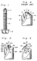
- the drill portion on a conventional drill screw is shaped as shown in Fig. 4 which is an enlarged view of the drill portion.
- a chisel 1 to set the position of the drill screw to the work piece is provided at the center tip of this drill screw.
- This chisel 1 is formed by the intersection of two relative planes 2 (only one of which is shown in Fig. 4) having a specific angle to the axis of the drill screw.
- the shape of the chisel forms a line perpendicular to the axis.
- cutting edges 3 and 4 following off ends 1a and 1b of the chisel 1 extend in a straight line towards outside face 5 of the drill screw, forming a general line of a conical shape centering on the axis of the drill screw.
- a conventional drill screw thus described has the following problems. Specifically, when a hole is opened in a work piece by the drill screw, a cutting load is applied to cutting edges 3 and 4. For any given material, if the angles of rakes of these cutting edges are the same, the cutting loads at this time increase as the lengths of the cutting edges 3 and 4 increase. In other words, the cutting load applied to the drill screw is dependent upon the diameter of the drill screw. As a result, there is a limit to the diameter of the drill screw which is manually drillable, and the problem exists that drill screws with diameters greater than or equal to 6.3 mm cannot be manually drilled in to a work piece.
- FIG. 14a shows a drill tip having a flat chisel end 31 formed with concave cutting edges 30 extending therefrom that are similar to the cutting edge 22 illustrated in Fig. 3 of the accompanying drawings, namely cutting edges curving back with respect to the rotational direction of the drill screw.
- the object of the present invention is to provide a drill screw with good cutting characteristics resistant to staggering.
- the present invention provides a drill screw comprising a drill portion on a tip of the drill screw, a threaded portion succeeding to the drill portion and a head succeeding to the threaded portion whereby a ridge on the threaded portion threads into an inside wall of a hole while the drill portion drills through a punctured object; said drill screw having cutting edges leading from both ends of a chisel positioned at the center of the tip of the drill screw each forming an arc curving to said head side in the axial direction and defining in association with said cutting edges two sharply cut ends projecting forwardly of the chisel in the axial direction; said two sharply cut ends being equally radially spaced from the drill axis and at the same distance from the drill head.
- the shape of the cutting edge forms an arc curving towards the head, i.e., the back in the axial direction. Therefore, the cutting load per unit length of cutting edge is less than that occurring when the shape of the cutting edge is a straight line. Furthermore, because the shape of the cutting edge forms an arc curving towards the back in the axial direction, the slope with respect to the axis of the curved cutting edge is less at the center portion and greater at the circumference portion when compared with a conventional straight cutting edge. On the other hand, the rotational speed of the drill screw is slow at the center portion and fast at the circumferential portion.
- the cutting load is significantly decreased at the center portion.
- the slope to the axis of the cutting edge at the outside circumference portion is greater than that of a conventional drill screw, but because the rotational speed is greater at the outside circumference portion, there is not a significant increase in the cutting load.
- the cutting load of the overall cutting edge is less than when the cutting edge forms a straight line. Therefore, the cutting load acting on the cutting edge is significantly reduced from that of a conventional cutting edge, and a hole can be easily opened in the work piece by rotation of the drill screw.
- a shape of the cutting edges forms an arc curving to a back in a rotational direction of the drill screw.
- the vertical component of the cutting load acting on the cutting edge is decreased, and a hole can be drilled even more easily.
- the shape of the chisel forms an arc curving to the head side in the axial direction.
- both ends of the chisel cut sharply towards the forwards due to the combined effect of the shape of the cutting edges leading from both ends of the chisel also forming an arc curving towards the back in the axial direction. Therefore, even when the drill screw cannot be held vertically to the surface of the work piece and is therefore at an angle to said surface, either end of the chisel can easily bite the work piece, and the position of the drill screw can be easily fixed.
- rake faces of the cutting edges are formed in two stages in the axial direction, a rake angle in the axial direction on a tip side being greater than a rake angle in the axial direction on the head side.
- a large rake angle in the axial direction can be obtained without making the slope of the rake face greater than that of a conventional drill screw, and a hole can be easily opened in the work piece.
- a drill screw according to the present invention reduces the cutting load acting on the cutting edge and improves cutting performance. Thus, worker fatigue is reduced and this drill screw is particularly effective in poor working conditions because cutting performance is good.
- a drill screw according to the present invention further improves cutting performance because the shape of the cutting edge forms an arc curving to the back in the direction of rotation.
- a drill screw according to the present invention because the shape of the chisel forms an arc curving to the back in the axial direction, this in combination with the shape of the cutting edge forming an arc curving to the back in the axial direction causes both ends of the chisel to cut sharply to the forwards. Therefore, even if the drill screw is at an angle to the surface of the work piece, the chisel easily bites into the work piece and cannot easily walk along the surface.
- a drill screw according to the present invention is particularly effective in poor working conditions because the tip does not walk and cutting performance is good.
- the rake angle at the tip of the rake face is formed greater than the rake angle at the base side in a drill screw, the rake angle of the tip only can be made larger while holding the slope of the cutting edge at the base approximately equal to the rake angle of a conventional drill screw. As a result, the rake angle of the cutting edge can be increased, and the cutting load can be further reduced.
- the tip does not walk and cutting performance is good, worker fatigue is low and the drill screw is ideally suited to use in poor working conditions.
- this drill screw comprises a drill portion 11, a threaded portion 12, and a head 13, and may be used as follows to fasten multiple metal sheets together. Specifically, the drill portion 11 of the above drill screw is pressed against the surface of the first metal sheet, and the head 13 is turned. Rotation of the head causes the drill portion 11 to pierce a hole in the multiple metal sheets layered together, and the thread ridge 14 on the threaded portion 12 threads in along the inside wall of the drilled hole. The multiple metal sheets are thus fastened together by tightening the drill screw.
- Figs. 2 and 3 are enlarged views of the drill portion 11 of the above drill screw; Fig. 2 is a front view, and Fig. 3 is a side view.
- the shape of the chisel 21 of the drill screw in the present invention is an arc curving towards the back in the axial direction.
- the cutting edges 22, 23 also each form an arc curving to the back in the axial direction.
- the ends 21a, 21b of the chisel 21 project forwardly of the chisel in the axial direction.
- the cutting edges 22, 23 form an arc curving towards the back in the axial direction and in the direction of rotation.
- the length along the edge of the cutting edges 22, 23 can be made longer than that when the cutting edges 22, 23 form a straight line. Therefore, the cutting load per unit length of the cutting edges 22, 23 can be reduced as compared with that of a conventional straight cutting edges.
- the slope of the curved cutting edges 22, 23 to the axis is less at the center than that formed by a conventional straight cutting edge.
- the slope of the cutting edges 22, 23 to the axis is greater at the outside than that formed by a conventional straight cutting edge.
- the rotational speed of the drill screw is slow at the center and fast at the outside circumference.
- the slope to the axis of the cutting edges 22, 23 at the center where the rotational speed is slow is smaller than that in a conventional drill screw, the cutting load acting at the center of the cutting edges 22, 23 is also significantly reduced.
- the slope of the cutting edges 22, 23 to the axis at the outside circumference is greater than that in a conventional drill screw.
- the rotational speed is fast at the outside circumference, the cutting load is not increased by a proportional degree. As a result, the cutting load applied overall to the cutting edges 22, 23 can be made less than that occurring with a straight cutting edge.
- the cutting edges 22, 23 are sloped at a given angle to the direction of advance (direction of rotation) of the cutting edges 22, 23.
- the vertical component of the cutting load to the cutting edges 22, 23 can be reduced, and cutting performance can be further improved.
- the cutting edges 22, 23 are arcs curving to the back in the axial direction.
- the cutting edges 3, 4 form an obtuse angle to the outside surface 5 as shown in Fig. 4 because the cutting edges 3, 4 form straight lines. Therefore, as the chisel 1 of the drill screw pierces the work piece and the edges 3a, 4a on the outside of the cutting edges 3, 4 approach the back of the work piece, the diameter of the hole rapidly approaches the diameter of the drill screw, and a minimal amount of uncut material remains immediately before the edges 3a, 4a of the cutting edges 3, 4 penetrate through to the back. This remaining minimal uncut material is thus forced to the outside of the hole by shear pressure resulting from the force applied to the drill screw in the axial direction, resulting in burrs on the back of the work piece.
- the cutting edges 22, 23 each form an arc curved to the back in the axial direction in a drill screw according to the present invention. Therefore, the cutting edges 22, 23 form a near perpendicular angle to the outside surface 26 as shown in Fig. 2.
- the uncut material remaining immediately before the ends 22a, 23a of the cutting edges 22, 23 penetrate to the back is greater than that when the angle of the cutting edges to the outside surface 26 is an obtuse angle.
- the last remaining uncut material is harder to push through to the back, and it is therefore cut by the cutting edges 22, 23. In other words, burrs do not occur at the back of the work piece with a drill screw according to the present invention.
- a special case of the formation of the cutting edges 22, 23 wherein each forms an arc curving to the back in the axial direction is that case wherein the angle of the cutting edge to the outside surface is an acute angle.
- the angle of the cutting edge to the outside surface is an acute angle.
- the rake angle ⁇ (hereinafter simply rake angle) in the axial direction of the rake face 24 (only one side shown in Fig. 3) forming one face of cutting edges 22, 23 is changed to an even larger rake angle ⁇ at a point 25 near the cutting edge tip.
- This makes it possible to obtain a large rake angle ⁇ only at the cutting edge tip while holding the slope to the axial direction at the bottom side of the rake face 24 at an angle approximately equal to the rake angle (e.g., ⁇ ) of a conventional drill screw. Therefore, cutting performance can be further improved with a rake face on the bottom side having a slope approximately equal to a conventional drill screw.
- the cutting edges 22, 23 in a drill screw according to the present invention each form an arc curving to the back in the axial and rotational directions. Therefore, the cutting load applied to the cutting edges 22, 23 can be reduced and the cutting performance of the drill screw can be improved.
- the shape of the chisel 21 also forms an arc curving to the back in the axial direction.
- This combined with the shape of the cutting edges 22, 23 being an arc curving to the back in the axial direction causes the ends 21a, 21b of the chisel 21 to cut sharply to the advancing direction. Therefore, even if the drill screw is at an angle to the surface of the work piece, the chisel 21 can easily bite the work piece and the drill screw be thus positioned, thus preventing the drill screw from walking across the surface of the work piece.
- a large rake angle ⁇ can be obtained by changing the rake angle of the rake face 24 to a large rake angle near the tip but without increasing the slope at the base of the cutting edge 22. Therefore, cutting performance can be further improved, thus improving work efficiency.
- the cutting performance of the drill screw is thus greatly improved with the present invention by forming the cutting edges 22, 23 of the drill screw as arcs curving to the back in the axial and rotational directions and making the rake angle ⁇ greater than that in a conventional drill screw as described hereinabove.
- the present invention makes it possible to manually drill a drill screw up to 8 mm diameter.
- a drill screw according to the present invention does not walk and has good cutting performance, worker fatigue is reduced, and this drill screw may be considered most ideally suited to poor working conditions.
- the shapes of the chisel 21 and the cutting edges 22, 23 in a drill screw according to the present invention are simple arcs curving to the back in the axial and rotational directions with the angle of the rake face 24 changing only at the tip. Therefore, the cutting edges 22, 23 can be easily formed by cold forging using two symmetrical tools each with matching rake faces.
- the two faces 27 (only one side shown in Fig. 2) leading to both ends of and forming the chisel 21 are concave faces, but this invention shall not be so limited. Essentially, it is sufficient if the shape of the chisel 21 is a surface forming an arc curving to the back in the axial direction.
Landscapes
- Engineering & Computer Science (AREA)
- General Engineering & Computer Science (AREA)
- Mechanical Engineering (AREA)
- Physics & Mathematics (AREA)
- Geometry (AREA)
- Drilling Tools (AREA)
Description
- The present invention relates to an improvement of a drill screw.
- Drill screws are self-tapping screws used to hold two members together by means of drill portions which pierces said two portions, ridges of threaded portion following the drill portions threading into holes so formed and heads.
- The drill portion on a conventional drill screw is shaped as shown in Fig. 4 which is an enlarged view of the drill portion. A chisel 1 to set the position of the drill screw to the work piece is provided at the center tip of this drill screw. This chisel 1 is formed by the intersection of two relative planes 2 (only one of which is shown in Fig. 4) having a specific angle to the axis of the drill screw. The shape of the chisel forms a line perpendicular to the axis. In addition, cutting
edges ends 1a and 1b of the chisel 1 extend in a straight line towardsoutside face 5 of the drill screw, forming a general line of a conical shape centering on the axis of the drill screw. - A conventional drill screw thus described has the following problems. Specifically, when a hole is opened in a work piece by the drill screw, a cutting load is applied to cutting
edges cutting edges - In addition, in environments with poor working conditions, it often occurs that the drill screw cannot be held perpendicular to the surface of the work piece, thus causing the drill screw to enter at an angle. In such cases, it is very hard for the chisel 1 to bite the work piece at the specified location. As a result, the reaction force of the work piece causes the tip of the drill screw to slide, causing the drill screw to walk across the surface without fixing the position of the drill hole.
- A prior art that is of interest is that disclosed in US-A-4 114 508. In this document a chisel is disclosed that is somewhat similar to that illustrated in the accompanying Fig. 4 illustrating prior art, one of the differences being, however, that instead of a straight edge 1 extending between the
tips 1a, 1b as in said Fig. 4, the edge 1 of this additional prior art is concave; further the tip 1a is located on the central longitudinal axis of the drill screw whilst thetip 1b is offset to one side from said central longitudinal axis and is closer to thehead 13 of the drill screw than is the tip 1a. - A further self tapping screw that is of interest is that disclosed in US-A-3 933 075 wherein Fig. 14a thereof shows a drill tip having a flat chisel end 31 formed with concave cutting edges 30 extending therefrom that are similar to the
cutting edge 22 illustrated in Fig. 3 of the accompanying drawings, namely cutting edges curving back with respect to the rotational direction of the drill screw. - The object of the present invention is to provide a drill screw with good cutting characteristics resistant to staggering.
- In order to accomplish the above object, the present invention provides a drill screw comprising a drill portion on a tip of the drill screw, a threaded portion succeeding to the drill portion and a head succeeding to the threaded portion whereby a ridge on the threaded portion threads into an inside wall of a hole while the drill portion drills through a punctured object;
said drill screw having cutting edges leading from both ends of a chisel positioned at the center of the tip of the drill screw each forming an arc curving to said head side in the axial direction and defining in association with said cutting edges two sharply cut ends projecting forwardly of the chisel in the axial direction;
said two sharply cut ends being equally radially spaced from the drill axis and at the same distance from the drill head. - In the present invention, the shape of the cutting edge forms an arc curving towards the head, i.e., the back in the axial direction. Therefore, the cutting load per unit length of cutting edge is less than that occurring when the shape of the cutting edge is a straight line. Furthermore, because the shape of the cutting edge forms an arc curving towards the back in the axial direction, the slope with respect to the axis of the curved cutting edge is less at the center portion and greater at the circumference portion when compared with a conventional straight cutting edge. On the other hand, the rotational speed of the drill screw is slow at the center portion and fast at the circumferential portion. Thus, because the slope to the axis of the cutting edge at the center portion where the rotational speed is slow is less than that of a conventional drill screw, the cutting load is significantly decreased at the center portion. It is to be noted that the slope to the axis of the cutting edge at the outside circumference portion is greater than that of a conventional drill screw, but because the rotational speed is greater at the outside circumference portion, there is not a significant increase in the cutting load. As a result, the cutting load of the overall cutting edge is less than when the cutting edge forms a straight line. Therefore, the cutting load acting on the cutting edge is significantly reduced from that of a conventional cutting edge, and a hole can be easily opened in the work piece by rotation of the drill screw.
- It is preferable that a shape of the cutting edges forms an arc curving to a back in a rotational direction of the drill screw.
- In the case that the shape of the cutting edge forms an arc curving towards the back in the direction of rotation, and the cutting edge slopes in the direction of cutting edge advance (i.e., the direction of rotation), the vertical component of the cutting load acting on the cutting edge is decreased, and a hole can be drilled even more easily.
- Furthermore, the shape of the chisel forms an arc curving to the head side in the axial direction.
- When the shape of the chisel forms an arc curving towards the back in the axial direction, both ends of the chisel cut sharply towards the forwards due to the combined effect of the shape of the cutting edges leading from both ends of the chisel also forming an arc curving towards the back in the axial direction. Therefore, even when the drill screw cannot be held vertically to the surface of the work piece and is therefore at an angle to said surface, either end of the chisel can easily bite the work piece, and the position of the drill screw can be easily fixed.
- Moreover, preferably, rake faces of the cutting edges are formed in two stages in the axial direction, a rake angle in the axial direction on a tip side being greater than a rake angle in the axial direction on the head side.
- In this case, a large rake angle in the axial direction can be obtained without making the slope of the rake face greater than that of a conventional drill screw, and a hole can be easily opened in the work piece.
- To sum up, the effects of the present invention are as follows.
- A drill screw according to the present invention reduces the cutting load acting on the cutting edge and improves cutting performance. Thus, worker fatigue is reduced and this drill screw is particularly effective in poor working conditions because cutting performance is good.
- In addition, a drill screw according to the present invention further improves cutting performance because the shape of the cutting edge forms an arc curving to the back in the direction of rotation.
- Furthermore, in a drill screw according to the present invention, because the shape of the chisel forms an arc curving to the back in the axial direction, this in combination with the shape of the cutting edge forming an arc curving to the back in the axial direction causes both ends of the chisel to cut sharply to the forwards. Therefore, even if the drill screw is at an angle to the surface of the work piece, the chisel easily bites into the work piece and cannot easily walk along the surface. Thus, a drill screw according to the present invention is particularly effective in poor working conditions because the tip does not walk and cutting performance is good.
- Furthermore, because the rake angle at the tip of the rake face is formed greater than the rake angle at the base side in a drill screw, the rake angle of the tip only can be made larger while holding the slope of the cutting edge at the base approximately equal to the rake angle of a conventional drill screw. As a result, the rake angle of the cutting edge can be increased, and the cutting load can be further reduced.
- Thus, because the tip does not walk and cutting performance is good, worker fatigue is low and the drill screw is ideally suited to use in poor working conditions.
-
- The present invention will become more fully understood from the detailed description given hereinbelow and the accompanying drawings which are given by way of illustration only, and thus are not limitative of the present invention, and wherein:
- Fig. 1 is an external view of a preferred embodiment of a drill screw according to the present invention;
- Fig. 2 is an enlarged front view of a drill portion in Fig. 1;
- Fig. 3 is an enlarged side view of the drill portion in Fig. 1;
- Fig. 4 is an enlarged view of a drill portion in a conventional drill screw.
- Before the description of the present invention proceeds, it is to be noted that like parts are designated by like reference numerals throughout the accompanying drawings.
- Referring now to Fig. 1, this drill screw comprises a
drill portion 11, a threadedportion 12, and ahead 13, and may be used as follows to fasten multiple metal sheets together. Specifically, thedrill portion 11 of the above drill screw is pressed against the surface of the first metal sheet, and thehead 13 is turned. Rotation of the head causes thedrill portion 11 to pierce a hole in the multiple metal sheets layered together, and thethread ridge 14 on the threadedportion 12 threads in along the inside wall of the drilled hole. The multiple metal sheets are thus fastened together by tightening the drill screw. - Figs. 2 and 3 are enlarged views of the
drill portion 11 of the above drill screw; Fig. 2 is a front view, and Fig. 3 is a side view. The shape of thechisel 21 of the drill screw in the present invention is an arc curving towards the back in the axial direction. Furthermore, thecutting edges ends 21a, 21b of thechisel 21 towards theoutside surface 26 of the drill screw, each form an arc curving towards the back in the axial direction as shown in Fig. 2, and additionally form an arc curving to the back in the direction of rotation as shown in Fig. 3. - As thus described, while the
chisel 21 forms an arc curving to the back in the axial direction, the cutting edges 22, 23 also each form an arc curving to the back in the axial direction. As a result, theends 21a, 21b of thechisel 21 project forwardly of the chisel in the axial direction. Thus, even when the drill screw cannot be held perpendicularly to the surface of the work piece, the sharply cutend 21a or 21b of thechisel 21 can easily catch the surface of the work piece, thereby enabling thechisel 21 to easily bite into the work piece. Therefore, even in poor working conditions where the drill screw is unavoidably placed at a slope to the surface of the work piece, the drill screw will not walk across the surface and the position of the hole can be easily fixed. - In addition, the cutting edges 22, 23 form an arc curving towards the back in the axial direction and in the direction of rotation. By being thus formed, the length along the edge of the cutting edges 22, 23 can be made longer than that when the cutting edges 22, 23 form a straight line. Therefore, the cutting load per unit length of the cutting edges 22, 23 can be reduced as compared with that of a conventional straight cutting edges. Moreover, because the cutting edges 22, 23 form an arc curving to the back in the axial direction, the slope of the
curved cutting edges - Thus, because the slope to the axis of the cutting edges 22, 23 at the center where the rotational speed is slow is smaller than that in a conventional drill screw, the cutting load acting at the center of the cutting edges 22, 23 is also significantly reduced. On the other hand, the slope of the cutting edges 22, 23 to the axis at the outside circumference is greater than that in a conventional drill screw. However, because the rotational speed is fast at the outside circumference, the cutting load is not increased by a proportional degree. As a result, the cutting load applied overall to the cutting edges 22, 23 can be made less than that occurring with a straight cutting edge.
- By thus reducing the cutting load acting on the cutting edges 22, 23, the cutting performance of the drill screw can be greatly improved.
- Furthermore, by shaping the cutting edges 22, 23 to form an arc curving to the back in the rotational direction, the cutting edges 22, 23 are sloped at a given angle to the direction of advance (direction of rotation) of the cutting edges 22, 23. As a result, the vertical component of the cutting load to the cutting edges 22, 23 can be reduced, and cutting performance can be further improved.
- Moreover, the following effects are obtained by forming the cutting edges 22, 23 as arcs curving to the back in the axial direction. Specifically, with a conventional drill screw, the
cutting edges outside surface 5 as shown in Fig. 4 because thecutting edges edges cutting edges edges cutting edges - On the other hand, the cutting edges 22, 23 each form an arc curved to the back in the axial direction in a drill screw according to the present invention. Therefore, the cutting edges 22, 23 form a near perpendicular angle to the
outside surface 26 as shown in Fig. 2. As a result, the uncut material remaining immediately before theends outside surface 26 is an obtuse angle. As a result, the last remaining uncut material is harder to push through to the back, and it is therefore cut by the cutting edges 22, 23. In other words, burrs do not occur at the back of the work piece with a drill screw according to the present invention. - Thus, a special case of the formation of the cutting edges 22, 23 wherein each forms an arc curving to the back in the axial direction is that case wherein the angle of the cutting edge to the outside surface is an acute angle. In this case, even if the end of the cutting edge on the outside in the radial direction approaches the back of the work piece, the diameter of the hole does not rapidly approach the diameter of the drill screw. Rather, the outside ends of the cutting edge in the radial direction reach the back of the work piece before that part of the cutting edge inside and near these outside ends. Therefore, before the last remaining uncut material is pushed outside the hole by the shear pressure from the drill screw, the uncut material is cut out by the outside edges of the cutting edge, and burrs thus do not occur at the back of the work piece.
- In addition, cutting performance is improved in the present invention as described below.
- Specifically, the rake angle β (hereinafter simply rake angle) in the axial direction of the rake face 24 (only one side shown in Fig. 3) forming one face of cutting
edges point 25 near the cutting edge tip. This makes it possible to obtain a large rake angle α only at the cutting edge tip while holding the slope to the axial direction at the bottom side of therake face 24 at an angle approximately equal to the rake angle (e.g., β) of a conventional drill screw. Therefore, cutting performance can be further improved with a rake face on the bottom side having a slope approximately equal to a conventional drill screw. - Because cutting performance is good with a large rake angle α, the uncut material remaining immediately before the
ends - As described hereinabove, the cutting edges 22, 23 in a drill screw according to the present invention each form an arc curving to the back in the axial and rotational directions. Therefore, the cutting load applied to the cutting edges 22, 23 can be reduced and the cutting performance of the drill screw can be improved.
- Furthermore, the shape of the
chisel 21 also forms an arc curving to the back in the axial direction. This combined with the shape of the cutting edges 22, 23 being an arc curving to the back in the axial direction causes theends 21a, 21b of thechisel 21 to cut sharply to the advancing direction. Therefore, even if the drill screw is at an angle to the surface of the work piece, thechisel 21 can easily bite the work piece and the drill screw be thus positioned, thus preventing the drill screw from walking across the surface of the work piece. Moreover, a large rake angle α can be obtained by changing the rake angle of therake face 24 to a large rake angle near the tip but without increasing the slope at the base of thecutting edge 22. Therefore, cutting performance can be further improved, thus improving work efficiency. - The cutting performance of the drill screw is thus greatly improved with the present invention by forming the cutting edges 22, 23 of the drill screw as arcs curving to the back in the axial and rotational directions and making the rake angle α greater than that in a conventional drill screw as described hereinabove. As a result, whereas 6.3 mm was the maximum diameter manually drillable with a conventional drill screw, the present invention makes it possible to manually drill a drill screw up to 8 mm diameter.
- Furthermore, because a drill screw according to the present invention does not walk and has good cutting performance, worker fatigue is reduced, and this drill screw may be considered most ideally suited to poor working conditions.
- The shapes of the
chisel 21 and the cutting edges 22, 23 in a drill screw according to the present invention are simple arcs curving to the back in the axial and rotational directions with the angle of therake face 24 changing only at the tip. Therefore, the cutting edges 22, 23 can be easily formed by cold forging using two symmetrical tools each with matching rake faces. - As shown in Fig. 2, the two faces 27 (only one side shown in Fig. 2) leading to both ends of and forming the
chisel 21 are concave faces, but this invention shall not be so limited. Essentially, it is sufficient if the shape of thechisel 21 is a surface forming an arc curving to the back in the axial direction. - The invention being thus described, it will be obvious that the same may be varied in many ways. Such variations as are included within the scope of the following claims are not to be regarded as a departure from the invention.
- Reference signs in the claims are intended for better understanding and shall not limit the scope.
Claims (4)
- A drill screw comprising a drill portion (11) on a tip of the drill screw, a theaded portion (12) succeeding to the drill portion (11) and a head (13) succeeding to the threaded portion (12) whereby a ridge (14) on the threaded portion (12) threads into an inside wall of a hole while the drill portion (11) drills through a punctured object;
said drill screw having cutting edges (22, 23) leading from both ends of a chisel (21) positioned at the center of the tip of the drill screw each forming an arc curving to a head side in an axial direction of the drill screw;
the chisel (21) being in the form of an arc curving to said head side in the axial direction and defining in association with said cutting edges (22, 23) two sharply cut ends (21a, 21b) projecting forwardly of the chisel (21) in the axial direction;
said two sharply cut ends (21a, 21b) being equally radially spaced from the drill axis and at the same distance from the drill head (13). - A drill screw according to Claim 1 wherein a shape of the cutting edges (22, 23) forms an arc curving to a back in a rotational direction of the drill screw.
- A drill screw according to Claim 1 wherein rake faces (24) of the cutting edges (22, 23) are formed in two stages in the axial direction, a rake angle (α) in the axial direction on a tip side being greater than a rake angle (β) in the axial direction on the head side; a rake angle being the angle formed between a rake face and a straight line parallel to the axis of the drill screw.
- A drill screw according to Claim 2 wherein rake faces (24) of the cutting edges (22, 23) are formed in two stages in the axial direction, a rake angle (α) in the axial direction on a tip side being greater than a rake angle (β) in the axial direction on the head side; a rake angle being the angle formed between a rake face and a straight line parallel to the axis of the drill screw.
Applications Claiming Priority (2)
| Application Number | Priority Date | Filing Date | Title |
|---|---|---|---|
| JP196930/90 | 1990-07-23 | ||
| JP2196930A JP2865823B2 (en) | 1990-07-23 | 1990-07-23 | Drill screw |
Publications (3)
| Publication Number | Publication Date |
|---|---|
| EP0468089A2 EP0468089A2 (en) | 1992-01-29 |
| EP0468089A3 EP0468089A3 (en) | 1992-04-22 |
| EP0468089B1 true EP0468089B1 (en) | 1994-10-12 |
Family
ID=16366029
Family Applications (1)
| Application Number | Title | Priority Date | Filing Date |
|---|---|---|---|
| EP90120785A Expired - Lifetime EP0468089B1 (en) | 1990-07-23 | 1990-10-30 | Drill screw having cutting edges each forming an arc curving to a head side |
Country Status (6)
| Country | Link |
|---|---|
| US (1) | US5074729A (en) |
| EP (1) | EP0468089B1 (en) |
| JP (1) | JP2865823B2 (en) |
| AU (1) | AU625007B2 (en) |
| DE (1) | DE69013340T2 (en) |
| FI (1) | FI905509A7 (en) |
Cited By (1)
| Publication number | Priority date | Publication date | Assignee | Title |
|---|---|---|---|---|
| EP2228551A2 (en) | 2009-03-03 | 2010-09-15 | HILTI Aktiengesellschaft | Self-drilling screw |
Families Citing this family (14)
| Publication number | Priority date | Publication date | Assignee | Title |
|---|---|---|---|---|
| ATE155204T1 (en) * | 1990-10-29 | 1997-07-15 | Bhp Eng Pty Ltd | SELF-CUTTING AS WELL AS SELF-CUTTING AND SELF-DRILLING MOUNTAIN ANCHORS |
| US5697746A (en) * | 1995-08-14 | 1997-12-16 | Emhart Inc. | Screw-nut fastener assembly |
| IL123858A (en) * | 1998-03-27 | 2003-05-29 | Iscar Ltd | Drilling head |
| US20040096293A1 (en) * | 2002-09-19 | 2004-05-20 | Mitek Holdings, Inc. | Truss screw |
| DE102006026176A1 (en) * | 2006-05-29 | 2007-12-06 | Adolf Würth GmbH & Co. KG | Self-drilling screw |
| US7841427B2 (en) * | 2008-07-18 | 2010-11-30 | Omni Ip Ltd. | Optimized central PDC cutter and method |
| JP2013083308A (en) * | 2011-10-11 | 2013-05-09 | Homn Reen Enterprise Co Ltd | Drill screw structure |
| US20130089390A1 (en) * | 2011-10-11 | 2013-04-11 | Huang-Jia Su | Structure of self-drilling screw |
| EP2581612A1 (en) * | 2011-10-14 | 2013-04-17 | Homn Reen Enterprise Co., Ltd. | Structure of self-drilling screw |
| US8864431B2 (en) * | 2012-03-14 | 2014-10-21 | Taiwan Shan Yin International Co., Ltd. | Screw capable of rapidly drilling and cutting |
| TWI560371B (en) * | 2013-10-22 | 2016-12-01 | Taiwan Shan Yin Int Co Ltd | A self-drilling screw |
| USD898557S1 (en) * | 2018-07-10 | 2020-10-13 | Screw King Co., Ltd. | Self drilling tapping screw |
| US11486433B2 (en) * | 2020-01-10 | 2022-11-01 | Taiwan Shan Yin International Co., Ltd. | Self-drilling screw |
| US11549543B2 (en) * | 2020-03-06 | 2023-01-10 | Hsiao-Wen Huang | Drill bit structure of self-tapping screw |
Citations (1)
| Publication number | Priority date | Publication date | Assignee | Title |
|---|---|---|---|---|
| US3937120A (en) * | 1975-01-28 | 1976-02-10 | Microdot Inc. | Drill screw |
Family Cites Families (10)
| Publication number | Priority date | Publication date | Assignee | Title |
|---|---|---|---|---|
| US3079831A (en) * | 1959-05-07 | 1963-03-05 | Illinois Tool Works | Screw having workpiece drilling and thread cutting point |
| US3463045A (en) * | 1966-05-10 | 1969-08-26 | Illinois Tool Works | Drilling screw |
| US3933075A (en) * | 1973-08-08 | 1976-01-20 | Elco Industries, Inc. | Self-drilling fastener and method of making same |
| GB1537701A (en) * | 1976-01-09 | 1979-01-04 | Avdel Ltd | Drills and self-drilling screws |
| US4125050A (en) * | 1977-06-06 | 1978-11-14 | J. Schwartzman Manufacturing & Supply Co. | Self-drilling screw |
| IT1083022B (en) * | 1977-07-21 | 1985-05-21 | Mustad O & Figlio Spa | SELF-PERFORATING AND SELF-THREADING SCREW |
| US4209275A (en) * | 1978-10-30 | 1980-06-24 | Kim Joo B | Twist drill |
| CA1175688A (en) * | 1979-11-26 | 1984-10-09 | Illinois Tool Works Inc. | Drill screw and cutters for making same |
| JPS597046B2 (en) * | 1979-12-29 | 1984-02-16 | 有限会社新城製作所 | drill screw |
| US4529341A (en) * | 1982-09-29 | 1985-07-16 | Hughes Helicopters, Inc. | Drill bit for Kevlar laminates |
-
1990
- 1990-07-23 JP JP2196930A patent/JP2865823B2/en not_active Expired - Fee Related
- 1990-10-12 US US07/596,373 patent/US5074729A/en not_active Expired - Lifetime
- 1990-10-25 AU AU64977/90A patent/AU625007B2/en not_active Ceased
- 1990-10-30 DE DE69013340T patent/DE69013340T2/en not_active Expired - Fee Related
- 1990-10-30 EP EP90120785A patent/EP0468089B1/en not_active Expired - Lifetime
- 1990-11-07 FI FI905509A patent/FI905509A7/en not_active Application Discontinuation
Patent Citations (1)
| Publication number | Priority date | Publication date | Assignee | Title |
|---|---|---|---|---|
| US3937120A (en) * | 1975-01-28 | 1976-02-10 | Microdot Inc. | Drill screw |
Cited By (2)
| Publication number | Priority date | Publication date | Assignee | Title |
|---|---|---|---|---|
| EP2228551A2 (en) | 2009-03-03 | 2010-09-15 | HILTI Aktiengesellschaft | Self-drilling screw |
| DE102009001298A1 (en) | 2009-03-03 | 2010-09-16 | Hilti Aktiengesellschaft | self-tapping |
Also Published As
| Publication number | Publication date |
|---|---|
| FI905509A0 (en) | 1990-11-07 |
| JPH0483913A (en) | 1992-03-17 |
| FI905509L (en) | 1992-01-24 |
| EP0468089A3 (en) | 1992-04-22 |
| DE69013340D1 (en) | 1994-11-17 |
| US5074729A (en) | 1991-12-24 |
| FI905509A7 (en) | 1992-01-24 |
| JP2865823B2 (en) | 1999-03-08 |
| DE69013340T2 (en) | 1995-03-23 |
| AU6497790A (en) | 1992-01-30 |
| AU625007B2 (en) | 1992-06-25 |
| EP0468089A2 (en) | 1992-01-29 |
Similar Documents
| Publication | Publication Date | Title |
|---|---|---|
| US5074729A (en) | Drill screw having cutting edges each forming an arc curving to a head side | |
| US4480951A (en) | Self-drilling screw | |
| CA2296883C (en) | Fastener having primary and secondary threads | |
| EP0933536B1 (en) | Threaded Anchor | |
| US4601625A (en) | Self drilling threaded insert for drywall | |
| US5234301A (en) | Hole forming and selftapping screw | |
| US5046905A (en) | Winged drill screw | |
| US5779417A (en) | Fastener having primary and secondary threads | |
| US5516248A (en) | Low torque wood screw | |
| EP0509173B1 (en) | Tapping screw | |
| US3093028A (en) | Self-drilling and self-tapping threaded fastener | |
| US6402448B1 (en) | Self-drilling and self-tapping screw | |
| JPH0610924A (en) | Concrete nail improvement | |
| US6142719A (en) | Self-drilling screw | |
| JP2004332933A (en) | Knurled fastener with cutting blade and removable head part | |
| US4114508A (en) | Self-drilling screw | |
| US4222689A (en) | Drilling and tapping screw | |
| US5520491A (en) | Drill screw | |
| US4347027A (en) | Drill screw | |
| CA1110092A (en) | Entering end portion of drill screw | |
| CA1042243A (en) | Drill screw | |
| JP4204905B2 (en) | Drilling tapping screw | |
| JP2002210708A (en) | Woodworking drill | |
| JPS6041243B2 (en) | Self-drilling screws and their rolling dies | |
| JPH0525013U (en) | Self-drilling screw with two-step cutting blade |
Legal Events
| Date | Code | Title | Description |
|---|---|---|---|
| PUAI | Public reference made under article 153(3) epc to a published international application that has entered the european phase |
Free format text: ORIGINAL CODE: 0009012 |
|
| 17P | Request for examination filed |
Effective date: 19901030 |
|
| AK | Designated contracting states |
Kind code of ref document: A2 Designated state(s): DE FR GB SE |
|
| PUAL | Search report despatched |
Free format text: ORIGINAL CODE: 0009013 |
|
| RIN1 | Information on inventor provided before grant (corrected) |
Inventor name: OBA, NOBORU |
|
| AK | Designated contracting states |
Kind code of ref document: A3 Designated state(s): DE FR GB SE |
|
| 17Q | First examination report despatched |
Effective date: 19930419 |
|
| GRAA | (expected) grant |
Free format text: ORIGINAL CODE: 0009210 |
|
| AK | Designated contracting states |
Kind code of ref document: B1 Designated state(s): DE FR GB SE |
|
| REF | Corresponds to: |
Ref document number: 69013340 Country of ref document: DE Date of ref document: 19941117 |
|
| EAL | Se: european patent in force in sweden |
Ref document number: 90120785.2 |
|
| ET | Fr: translation filed | ||
| PLBE | No opposition filed within time limit |
Free format text: ORIGINAL CODE: 0009261 |
|
| STAA | Information on the status of an ep patent application or granted ep patent |
Free format text: STATUS: NO OPPOSITION FILED WITHIN TIME LIMIT |
|
| 26N | No opposition filed | ||
| PGFP | Annual fee paid to national office [announced via postgrant information from national office to epo] |
Ref country code: SE Payment date: 19980914 Year of fee payment: 9 |
|
| PGFP | Annual fee paid to national office [announced via postgrant information from national office to epo] |
Ref country code: GB Payment date: 19981030 Year of fee payment: 9 Ref country code: FR Payment date: 19981030 Year of fee payment: 9 |
|
| PGFP | Annual fee paid to national office [announced via postgrant information from national office to epo] |
Ref country code: DE Payment date: 19981113 Year of fee payment: 9 |
|
| PG25 | Lapsed in a contracting state [announced via postgrant information from national office to epo] |
Ref country code: SE Free format text: THE PATENT HAS BEEN ANNULLED BY A DECISION OF A NATIONAL AUTHORITY Effective date: 19991030 Ref country code: GB Free format text: LAPSE BECAUSE OF NON-PAYMENT OF DUE FEES Effective date: 19991030 |
|
| EUG | Se: european patent has lapsed |
Ref document number: 90120785.2 |
|
| GBPC | Gb: european patent ceased through non-payment of renewal fee |
Effective date: 19991030 |
|
| PG25 | Lapsed in a contracting state [announced via postgrant information from national office to epo] |
Ref country code: FR Free format text: LAPSE BECAUSE OF NON-PAYMENT OF DUE FEES Effective date: 20000630 |
|
| PG25 | Lapsed in a contracting state [announced via postgrant information from national office to epo] |
Ref country code: DE Free format text: LAPSE BECAUSE OF NON-PAYMENT OF DUE FEES Effective date: 20000801 |
|
| REG | Reference to a national code |
Ref country code: FR Ref legal event code: ST |