EP0467873B1 - Mechanical flexure for motion amplification and transducer with same - Google Patents
Mechanical flexure for motion amplification and transducer with same Download PDFInfo
- Publication number
- EP0467873B1 EP0467873B1 EP91870112A EP91870112A EP0467873B1 EP 0467873 B1 EP0467873 B1 EP 0467873B1 EP 91870112 A EP91870112 A EP 91870112A EP 91870112 A EP91870112 A EP 91870112A EP 0467873 B1 EP0467873 B1 EP 0467873B1
- Authority
- EP
- European Patent Office
- Prior art keywords
- flexure element
- pressure
- legs
- leg
- fluid
- Prior art date
- Legal status (The legal status is an assumption and is not a legal conclusion. Google has not performed a legal analysis and makes no representation as to the accuracy of the status listed.)
- Expired - Lifetime
Links
Images


Classifications
-
- F—MECHANICAL ENGINEERING; LIGHTING; HEATING; WEAPONS; BLASTING
- F15—FLUID-PRESSURE ACTUATORS; HYDRAULICS OR PNEUMATICS IN GENERAL
- F15B—SYSTEMS ACTING BY MEANS OF FLUIDS IN GENERAL; FLUID-PRESSURE ACTUATORS, e.g. SERVOMOTORS; DETAILS OF FLUID-PRESSURE SYSTEMS, NOT OTHERWISE PROVIDED FOR
- F15B5/00—Transducers converting variations of physical quantities, e.g. expressed by variations in positions of members, into fluid-pressure variations or vice versa; Varying fluid pressure as a function of variations of a plurality of fluid pressures or variations of other quantities
- F15B5/003—Transducers converting variations of physical quantities, e.g. expressed by variations in positions of members, into fluid-pressure variations or vice versa; Varying fluid pressure as a function of variations of a plurality of fluid pressures or variations of other quantities characterised by variation of the pressure in a nozzle or the like, e.g. nozzle-flapper system
-
- G—PHYSICS
- G05—CONTROLLING; REGULATING
- G05D—SYSTEMS FOR CONTROLLING OR REGULATING NON-ELECTRIC VARIABLES
- G05D16/00—Control of fluid pressure
- G05D16/20—Control of fluid pressure characterised by the use of electric means
- G05D16/2006—Control of fluid pressure characterised by the use of electric means with direct action of electric energy on controlling means
- G05D16/2013—Control of fluid pressure characterised by the use of electric means with direct action of electric energy on controlling means using throttling means as controlling means
-
- H—ELECTRICITY
- H10—SEMICONDUCTOR DEVICES; ELECTRIC SOLID-STATE DEVICES NOT OTHERWISE PROVIDED FOR
- H10N—ELECTRIC SOLID-STATE DEVICES NOT OTHERWISE PROVIDED FOR
- H10N30/00—Piezoelectric or electrostrictive devices
- H10N30/20—Piezoelectric or electrostrictive devices with electrical input and mechanical output, e.g. functioning as actuators or vibrators
-
- H—ELECTRICITY
- H10—SEMICONDUCTOR DEVICES; ELECTRIC SOLID-STATE DEVICES NOT OTHERWISE PROVIDED FOR
- H10N—ELECTRIC SOLID-STATE DEVICES NOT OTHERWISE PROVIDED FOR
- H10N35/00—Magnetostrictive devices
-
- Y—GENERAL TAGGING OF NEW TECHNOLOGICAL DEVELOPMENTS; GENERAL TAGGING OF CROSS-SECTIONAL TECHNOLOGIES SPANNING OVER SEVERAL SECTIONS OF THE IPC; TECHNICAL SUBJECTS COVERED BY FORMER USPC CROSS-REFERENCE ART COLLECTIONS [XRACs] AND DIGESTS
- Y10—TECHNICAL SUBJECTS COVERED BY FORMER USPC
- Y10T—TECHNICAL SUBJECTS COVERED BY FORMER US CLASSIFICATION
- Y10T137/00—Fluid handling
- Y10T137/2278—Pressure modulating relays or followers
-
- Y—GENERAL TAGGING OF NEW TECHNOLOGICAL DEVELOPMENTS; GENERAL TAGGING OF CROSS-SECTIONAL TECHNOLOGIES SPANNING OVER SEVERAL SECTIONS OF THE IPC; TECHNICAL SUBJECTS COVERED BY FORMER USPC CROSS-REFERENCE ART COLLECTIONS [XRACs] AND DIGESTS
- Y10—TECHNICAL SUBJECTS COVERED BY FORMER USPC
- Y10T—TECHNICAL SUBJECTS COVERED BY FORMER US CLASSIFICATION
- Y10T137/00—Fluid handling
- Y10T137/2278—Pressure modulating relays or followers
- Y10T137/2409—With counter-balancing pressure feedback to the modulating device
Definitions
- This invention relates to a mechanical flexure element for motion amplification and to electromechanical transducer devices incorporating such a mechanical flexure element.
- the European patent application EP-A-0 375 093 discloses a sensitive electrical to mechanical transducer.
- a flexure element is provided formed of a rigid material and having two legs extending along respective longitudinal axes. One of the legs serves as a coupling arm and has a magnetic material connected thereto. The magnetic material is located in an opening of a coil winding adapted to carry current to produce a magnetic field.
- the coupling arm is movable in response to movement of the magnetic material to provide a mechanical output of the transducer.
- a flexure element that can be used to amplify or increase small motions into larger motions.
- a sensing element is subjected to or undergoes a slight displacement which is to be detected to provide a motion indication or a quantitative motion measurement.
- Such motion amplification devices are extremely desirable for example for use with piezoelectric, magnetostrictive, or electrostrictive elements, and other such types of transducers in the detection or sensing of very small displacements in the micron range, i.e., micro-meter range.
- the desirable flexure element should provide the following advantages over conventional lever mechanisms: (1) simple, low-cost structure and method of manufacture; (2) providing high amplification ratio for very small displacements; (3) significantly reduced lost motion characteristics; (4) very linear for small displacements; (5) low hysteresis; (6) low sensitivity to temperature changes; and (7) rugged, reliable structure with long lasting performance.
- Electromechanical transducers have been used for many years to transform, for instance, electrical signals into a mechanical motion, and vice versa. Such transducers find application in a variety of circumstances, including fluid flow control devices, fluid flow indicating and measuring devices, etc. A particular need is for a reliable electromechanical transducer which can respond to very small electrical signals to provide micro-motion in a transducer element or a moving member connected to the transducer element.
- Prior electromechanical transducers have utilized piezoelectric substances, Rochelle salt, or electrostrictive materials, such as polycrystalline ceramics.
- a flexure element as defined in claim 1.
- the flexure element may be made of metal, plastic, fiber or other similarly rigid material that can be used to amplify very small motions into larger motions and which provides all of the desired advantages over conventional lever mechanisms.
- the flexure element has a closed end and two legs extending therefrom along respective longitudinal axes. Moving a first leg in longitudinal displacement with respect to the other through displacement means coupled to the first leg provides a larger amplified transverse displacement of the closed end with respect to the longitudinal axes.
- one end of one leg may be fixedly mounted in position.
- Moving the other leg by for instance small longitudinal displacements generated by displacement means, such as magnetostrictive, electrostrictive or piezoelectric devices attached or coupled to the longitudinally moved leg enables the flexure or bender element to bend towards or away from the longitudinal axes which displaces the free closed end transversely to the longitudinal axes.
- Very small displacements of the moving leg such as generated by the micron-sized displacements of a magnetostrictive device in response to a magnetic field, provides an amplified larger transverse movement of the free closed end of the flexure element.
- small longitudinal leg displacements are translated into much larger closed end displacements transverse to the longitudinal axis.
- Amplification ratios of 30/l have been obtained in constructed embodiments of a bender element according to this invention.
- the flexure element in accordance with the present invention can be utilized in electromechanical transducers, such as a current to pressure transducer, in an electro-pneumatic relay, and in a control valve actuator.
- electromechanical transducers such as a current to pressure transducer
- electro-pneumatic relay such as a current to pressure transducer
- control valve actuator such as a control valve actuator
- the flexural or bender element provides a very simple, low-cost flexure device with a high amplification ratio, very linear output movements for small displacements, very low lost motion characteristics, low hysteresis, low sensitivity to temperature changes, and is rugged, reliable and capable of providing long lasting performance.
- an electromechanical transducer as defined in claim 14 and claim 20.
- a current to pressure transducer is one embodiment of this invention, and includes a bender or flexure element to amplify micron-sized displacement from a magnetostrictive element.
- Current flowing through the coil of the magnetostrictive material causes the material to elongate.
- the motion of the magnetostrictive element is transmitted to the bender device, causing the free closed end of the bender device to move with greatly amplified motion.
- the current to pressure transducer includes a nozzle chamber with the flexure or bender element mounted so as to control the fluid pressure passing from the nozzle chamber through the nozzle.
- pressure in the nozzle chamber may increase.
- This increased nozzle chamber pressure acts upon a feedback diaphragm attached to the flexure element and the magnetostrictive material to develop a compressive force which tends to restore the magnetostrictive material to its original length.
- the feedback force exerted on the diaphragm equals the electrical input force generated through the magnetostrictive element, the resulting output pressure from the nozzle chamber is proportional to the magnetostrictive element coil input current.
- Electromechanical transducers with the flexure or bender element of the present invention can be provided. Piezoelectric or electrostrictive elements can be utilized rather than a magnetostrictive element.
- a pressure transducer is also provided by the present invention as defined in claim 21.
- the flexure or bender element also can be used with other force or pressure elements, such as bellows, bourdon tubes, diaphragms, solenoids, voice coils, etc., for inducing small primary motions in a flexure leg which are translated and amplified into larger movements of the closed end of the flexure element.
- the flexure element also can be adapted for load amplification. Outputs with large motion displacements but low forces can be converted into outputs of high loading with small motion displacements.
- Motions also can be attenuated using the flexure element. For instance, large displacement motions input to the flexure element closed end can be converted into extremely accurate small movements of a flexure leg suitable for precise object positioning, measurements, etc.
- a flexure or bender device may have one fixed leg and one movable leg, or may have both legs movable with respect to each other. Both embodiments, of course, utilize one leg movable in elongated displacement with respect to the other leg with resulting motion amplification and translation of the closed end of the bender device, or the reverse, i.e., large displacements of the closed end with a resulting attenuated motion displacement of one leg with respect to the other.
- Flexure or bender element 10 is formed of metal, plastic, fiber or other similarly rigid material into a member with closed end 12 and respective legs 14, 16 extending therefrom. End 18 of leg 14 is fixed in position such as schematically illustrated by a fixed mounting block 20 to a ground reference 22. End 24 of opposite leg 16 is mounted to a movable member 26 which can be a part of or connected to a magnetostrictive, electrostrictive or piezoelectric device or to a force or pressure element providing very small, micron-sized longitudinal displacements of leg 16.
- a magnetostrictive device or a bellows formed as movable member 26 can generate linear micro-displacements of leg 16 in the directions indicated by reference arrow 28.
- a magnetostrictive member or a bellows formed as movable member 26 moves leg 16 in a linear displacement in direction A shown with respect to reference arrow 28, flexural element 10 will bend so that closed free end 12 will be displaced downwardly as indicated by direction C of reference arrow 30.
- micro-motions of leg 16 in direction B of reference arrow 28 will bend free closed end 12 upwardly in direction D of reference arrow 32. Linear longitudinal displacements of leg 16 are therefore translated in amplified transverse displacements of closed end 12.
- flexural element 10 was constructed of type 304 stainless steel material having the following dimensions: flexure leg length - 50.04 mm; flexure leg width - 5.64 mm; each leg thickness - 0.381 mm; and the legs being substantially adjacent each other over their length.
- any other rigid type material with linear elastic characteristics may be utilized.
- increasing the gap between legs 14, 16 tends to decrease the stiffness of the flexure element and thereby lessen the amount of force required for primary motion displacement of a moving leg.
- increasing the gap also tends to reduce the amplification gain of the flexure or bender device.
- decreasing the gap increases the gain of the flexure element, this tends to increase the overall stiffness of the flexure element to input motion so that significantly more force is required to obtain primary motion displacement of a moving leg.
- Transducer housing 42 includes an enclosed nozzle chamber 44 for containing fluid under pressure supplied through an inlet port 46 containing a primary restrictor 48.
- An outlet port 50 communicates with nozzle chamber 44 to provide a fluid output pressure from transducer 40.
- a nozzle 52 is mounted in housing 42 with a control nozzle end 54 extending within nozzle chamber 44 and with an exhaust nozzle end 56 communicating nozzle chamber 44 with an exhaust port 58.
- Flexure element 10 is cantilever mounted in nozzle chamber 44 with free closed end 12 above the control nozzle end.
- flexure element leg 14 is fixedly mounted to an abutment 60 to maintain flexure element 10 in the position shown in Figure 2.
- Leg 16 is connected to a movable magnetic core 62 at one end and with the other end of core 62 being connected to a magnetostrictive rod 64 which in turn has its opposite end mounted to magnetic housing 66.
- Magnetostrictive rod 64 can be formed of magnetostrictive material which responds to a magnetic field produced by current flowing in coil 68 to induce a strain in the magnetostrictive material and thereby elongate the material.
- Such magnetostrictive material is well known and is normally formed of alloys of rare earth elements with iron.
- Presently available rare earth magnetostrictive materials produce large strains up to approximately 2,000 ppm (parts per million) for an imposed magnetic field as a result of a current in surrounding coil 68.
- rod 64 be formed of a magnetostrictive material sold with the trademark "TERFENOL-D", which is currently available from Edge Technologies, Inc. of Ames, Iowa.
- nozzle chamber 44 One end of nozzle chamber 44 is sealed by means of a flexible feedback diaphragm 72 which in turn is mounted to movable magnetic core 62.
- a flexible feedback diaphragm 72 which in turn is mounted to movable magnetic core 62.
- enclosed nozzle chamber 44 within housing 42 has openings through inlet port 46, outlet port 50 and exhaust port 58 and is sealed at the opposite end by means of a flexible diaphragm 72.
- the outer perimeter of diaphragm 72 is mounted to housing 42 and the inner perimeter is mounted into movable magnetic core 62.
- Feedback diaphragm 72 may be constructed of a thin metal material such as type 316 stainless steel.
- Electromechanical transducer 40 transforms electrical energy in the form of an electrical current supplied to wires 70 into mechanical energy in the form of fluid pressure supplied from fluid outlet port 50.
- a transducer is particularly useful in for instance an electronic control loop where the final control element, generally a control valve, is pneumatically operated.
- the transducer receives a milliampere of direct current input signal such as on wires 70 and transmits a proportional pneumatic output pressure on output port 50 to a final control element which may control the flow of fluid in a fluid pipeline system.
- an electrical current supplied to wires 70 and flowing in coil 68 produces a magnetostrictive strain in the magnetostrictive material forming magnetostrictive rod 64 so as to elongate rod 64 and transmit this micro-motion through feedback diaphragm 72 and movable magnetic core 62 to leg 16 of bender 10.
- This linear micro-motion displacement of leg 16 causes free closed end 12 of the flexure element to move toward control nozzle end 54 with a greatly amplified motion as shown in Figure 3.
- FIG. 1 shows an exaggerated illustration of the micro-movement x of leg 16. The feedback compression against diaphragm 72 continues until the feedback force balances the electrical input force inducing the movement of magnetostrictive rod 64 to thereby establish an output pressure on fluid output port 50 which is proportional to the input current.
- bending of flexure element 10 towards or away from control nozzle end 54 changes the fluid output pressure on fluid output port 50 so as to change the pressure in nozzle chamber 44 acting against feedback diaphragm 72 and to change the resulting feedback force until the final fluid output pressure at port 50 is proportional to the electrical current value present at wires 70.
- FIG. 4 An alternative current to pressure transducer is shown in Figure 4 wherein the prior feedback on diaphragm 72 has been eliminated.
- the supply pressure is coupled to a T-fitting 74 through a primary restrictor 76 and communicates with output line 78.
- the output pressure on line 78 is directly responsive to the input current value at wires 70.
- the output pressure in this case is more sensitive to the input, but, without feedback, is less linear and less precise compared to the current to pressure transducer of Figures 2, 3.
- leg 14 or 16 can be fixed in position while the other leg is moved so as to obtain the motion amplification and translation of small displacements.
- the flexure element 10 of the present invention is particularly useful when small, micron-sized displacements are generated by magnetostrictive, electrostrictive or piezoelectric devices. Such combinations find practical application in actuators and transducers, such as current to pressure transducers, electro-pneumatic relays, and control valve actuators.
- both legs may be movable with respect to each other.
- Such a device may be utilized as a motion averaging or summing transducer unit wherein first and second inputs can be coupled to a respective leg and the input displacements generate amplified transverse movements of the free closed end corresponding to the difference between the two inputs.
- Figures 5-11 Other application embodiments of a flexure or bender element in accordance with this aspect of the invention are illustrated in Figures 5-11.
- Figures 5-8 and 11 illustrate a flexure element in various applications using the motion amplification and translation features of such a flexure element;
- Figure 9 illustrates a flexure element to attenuate large motions and provide precise smaller motions for positioning of surfaces or probes;
- Figure 10 illustrates a flexure element embodiment used to sum pressure and motion inputs.
- Figure 5 illustrates an embodiment 79 having flexure or bender 10 with fixed leg 14 mounted to a stationery member such as fixed mounting block 20, and with moving leg 16 coupled to a diaphragm 80 through a connecting flange 82.
- the diaphragm is mounted in block 20 so as to provide an enclosed pressure chamber 84 receiving an input fluid pressure through an inlet 86.
- the pressure at inlet 86 and in chamber 84 acts on diaphragm 80 to move leg 16 in directions A or B to provide motion amplification and translation along respective directions C or D.
- the bender embodiment of Figure 5 converts pressure to motion using a single diaphragm.
- Figure 6 illustrates another bender application embodiment 87 in which the bender element converts pressure to motion using a bellows 88 to which is coupled a fluid pressure through inlet 86.
- Figure 7 illustrates another bender embodiment 89 which is responsive to both input fluid pressure on inlet 86 and input fluid pressure on inlet 90 and converts the output motion along respective directions C, D using a diaphragm stack.
- a first enclosed chamber 84 in fixed mounting block 20 is provided by diaphragm 80.
- a second chamber 92 is provided by diaphragm 94 wherein fluid pressure inlet 90 communicates with chamber 92.
- Figure 8 illustrates another embodiment 96 in which a flexure or bender element 10 is used to operate a spool valve 98.
- Fixed leg 14 is mounted to fixed mounting block 20 and moving leg 16 is connected through a suitable drive means to cause motion displacements along directions A, B.
- Closed end 12 is mounted to valve rod 100 to thereby move the valve members 101 along directions C, D in response to input motions A, B.
- Operating valve rod 100 along motion directions C, D respectively couples the supply pressure in spool valve 98 to output pressure 1 or output pressure 2.
- the flexure element application embodiment 102 of Figure 9 provides motion attenuation rather than motion amplification.
- Fixed leg 14 is again mounted to a fixed mounting block 20.
- Movable leg 16 is mounted to a free end 103 of a flexible member 105 having the opposite end 107 fixed in position by mounting to a fixed mounting block 20.
- flexing or pivoting end 103 would include a special surface, probe, switch elements, or other devices utilizing the small output displacement in directions A, B of end 103 in response to large motion inputs in directions C, D at flexure element closed end 12.
- a bender element 10 is used to provide precise motion attenuation for precise positioning of laser mirrors, etc. on moving end 103.
- FIG. 10 there is illustrated an alternative application embodiment 104 using a bender element 11 with legs 16, 17 each of which is movable with respect to each other to provide an amplified translated motion along directions C, D.
- Moving leg 16 is mounted to bellows 88 receiving fluid pressure through inlet line 86. Longitudinal displacements along directions A, B are therefore in direct response to the pressure at inlet line 86.
- Movable leg 17 also may be displaced longitudinally along directions A′, B′ in response to a drive motion means connected to end 23 of leg 17.
- flexure element closed end 12 moves in directions C, D in response to the difference between the motion inputs to legs 16, 17.
- closed end 12 moves in amplified transverse direction C. If the legs are moved in directions A′, B, closed end 12 moves in direction D. If the legs are moved in respective directions A, A′ or B, B′, closed end 12 does not move in the transverse direction.
- leg 17 is displaced by means of the movements of a platform 106 having a rotating wheel 108 in contact with cam surface 110 of an eccentric cam 112.
- Eccentric cam 112 is fixed to and driven by a rotatable shaft 114 which is rotatably mounted in a fixed frame 116.
- shaft 114 is rotated in the indicated clockwise or counter-clockwise directions, eccentric cam 12 is rotated to move plate 106 upwardly or downwardly, thereby providing the displacement motions of leg 17 along directions A′, B′.
- a hinge member 118 may be used to connect plate 106 to a fixed frame 120.
- Nozzle 122 is mounted adjacent closed end 12 and is supplied with a fluid flow. thus, the fluid flow and pressure at nozzle 122 is controlled by the movement of closed end 12 in directions C, D.
- bender element 11 is responsive to the pressure at input 86 and the motion input on shaft 114.
- Embodiment 104 therefore has applications in the construction of process controllers and valve positioners.
- FIG 11 illustrates another embodiment 130 comprising a proportional solenoid current to pressure transducer.
- Embodiment 130 includes a bender element 10 for converting an electric current into a variable flow rate from nozzle outlet 132 using a solenoid 134.
- Fixed leg 14 is mounted to a rigid, fixed portion of solenoid 134.
- Displaceable leg 16 is mounted to a free end of solenoid armature 136 with the other end being hingedly mounted to the solenoid by hinge means 138.
- a source of pneumatic pressure is coupled to a T-fitting 140 through a fixed metering orifice or primary restrictor 142 and communicates with output line 146.
- the proportional current to pressure transducer makes use of the flexure 10 to minimize the amount of travel required of the solenoid's armature.
- Reduced armature travel allows the solenoid to be designed to operate in a stable region and therefore act in a proportional manner in response to changes in electrical current rather than the snap acting manner commonly associated with solenoid operation.
- the solenoid armature 136 slowly moves towards and away from the solenoid 134 in response to the input solenoid coil current due to the stiffness of element 10.
- These small motion displacements along directions A, B are translated into amplified displacements C, D of closed end 12 to provide a variable flow rate from nozzle 132.
- This embodiment eliminates the hysteresis due to pivots, bearings, etc. commonly encountered in other transducer designs.
Landscapes
- Physics & Mathematics (AREA)
- Fluid Mechanics (AREA)
- Engineering & Computer Science (AREA)
- General Physics & Mathematics (AREA)
- Automation & Control Theory (AREA)
- Mechanical Engineering (AREA)
- General Engineering & Computer Science (AREA)
- General Electrical Machinery Utilizing Piezoelectricity, Electrostriction Or Magnetostriction (AREA)
- Supply Devices, Intensifiers, Converters, And Telemotors (AREA)
- Transmission And Conversion Of Sensor Element Output (AREA)
- Measuring Fluid Pressure (AREA)
Description
- This invention relates to a mechanical flexure element for motion amplification and to electromechanical transducer devices incorporating such a mechanical flexure element.
- Reference may be made to the following U.S. patents of interest concerning mechanical flexure elements: 4,748,858; 3,638,481; 3,370,458; 3,151,693; 3,848,462; 2,963,904.
- The European patent application EP-A-0 375 093 discloses a sensitive electrical to mechanical transducer. A flexure element is provided formed of a rigid material and having two legs extending along respective longitudinal axes. One of the legs serves as a coupling arm and has a magnetic material connected thereto. The magnetic material is located in an opening of a coil winding adapted to carry current to produce a magnetic field. The coupling arm is movable in response to movement of the magnetic material to provide a mechanical output of the transducer.
- In many applications, it is desired to provide a flexure element that can be used to amplify or increase small motions into larger motions. One example of such a desirable use for such a device is in instrumentation where for example a sensing element is subjected to or undergoes a slight displacement which is to be detected to provide a motion indication or a quantitative motion measurement. Such motion amplification devices are extremely desirable for example for use with piezoelectric, magnetostrictive, or electrostrictive elements, and other such types of transducers in the detection or sensing of very small displacements in the micron range, i.e., micro-meter range.
- Present motion amplification devices such as lever mechanisms suggested for micro-meter range sensing have major drawbacks in certain areas such as reaction to temperature changes, fragile structure, low motion amplification, high lost motion characteristics, high hysteresis losses, or costly materials or methods of manufacturing. Accordingly, it is desired to provide a mechanical flexure which can be sized to amplify very small, micron displacements generated for instance by magnetostrictive, electrostrictive and piezoelectric elements, so as to be adaptable for use in practical actuator and transducer units. The desirable flexure element should provide the following advantages over conventional lever mechanisms: (1) simple, low-cost structure and method of manufacture; (2) providing high amplification ratio for very small displacements; (3) significantly reduced lost motion characteristics; (4) very linear for small displacements; (5) low hysteresis; (6) low sensitivity to temperature changes; and (7) rugged, reliable structure with long lasting performance.
- Reference may also be made to the following U.S. patents of interest with respect to electromechanical transducers: 4,701,660; 4,158,368; 4,025,942; 3,370,458; 3,218,445; 2,992,373; 2,904,735; 2,769,867; 2,419,061; and to the publication, "Application Manual For The Design of Etrema TERFENOL-DTM Magnetostrictive Transducers", J.L. Butler, Edge Technologies, Inc. 1988.
- Electromechanical transducers have been used for many years to transform, for instance, electrical signals into a mechanical motion, and vice versa. Such transducers find application in a variety of circumstances, including fluid flow control devices, fluid flow indicating and measuring devices, etc. A particular need is for a reliable electromechanical transducer which can respond to very small electrical signals to provide micro-motion in a transducer element or a moving member connected to the transducer element. Prior electromechanical transducers have utilized piezoelectric substances, Rochelle salt, or electrostrictive materials, such as polycrystalline ceramics.
- Recently, in the desire to obtain more sensitive and faster acting electromechanical transducers, the introduction of magnetostrictive materials to such transducers has been proposed, such as is disclosed in the above indicated US-A- 4,158,368. This patent proposes the use of a magnetostrictive material with coupled members movable by the magnetostrictive material when placed in a magnetic field. Several embodiments are illustrated in this patent including, a valve plunger, a plate having apertures in another valve configuration, and two sliding plates with apertures selectively alignable in another valve configuration.
- It is desirable to provide a flexure element and an electromechanical transducer for sensing and producing micro-motions in a more simple structural and operating configuration compared to prior suggested devices.
- In accordance with the present invention, there is provided a flexure element as defined in claim 1. The flexure element may be made of metal, plastic, fiber or other similarly rigid material that can be used to amplify very small motions into larger motions and which provides all of the desired advantages over conventional lever mechanisms. The flexure element has a closed end and two legs extending therefrom along respective longitudinal axes. Moving a first leg in longitudinal displacement with respect to the other through displacement means coupled to the first leg provides a larger amplified transverse displacement of the closed end with respect to the longitudinal axes.
- As an example, one end of one leg may be fixedly mounted in position. Moving the other leg by for instance small longitudinal displacements generated by displacement means, such as magnetostrictive, electrostrictive or piezoelectric devices attached or coupled to the longitudinally moved leg enables the flexure or bender element to bend towards or away from the longitudinal axes which displaces the free closed end transversely to the longitudinal axes. Very small displacements of the moving leg, such as generated by the micron-sized displacements of a magnetostrictive device in response to a magnetic field, provides an amplified larger transverse movement of the free closed end of the flexure element. Thus, small longitudinal leg displacements are translated into much larger closed end displacements transverse to the longitudinal axis. Amplification ratios of 30/l have been obtained in constructed embodiments of a bender element according to this invention.
- The flexure element in accordance with the present invention can be utilized in electromechanical transducers, such as a current to pressure transducer, in an electro-pneumatic relay, and in a control valve actuator. In particular, the flexural or bender element provides a very simple, low-cost flexure device with a high amplification ratio, very linear output movements for small displacements, very low lost motion characteristics, low hysteresis, low sensitivity to temperature changes, and is rugged, reliable and capable of providing long lasting performance.
- Also in accordance with the present invention, there is provided an electromechanical transducer as defined in
claim 14 and claim 20. A current to pressure transducer is one embodiment of this invention, and includes a bender or flexure element to amplify micron-sized displacement from a magnetostrictive element. Current flowing through the coil of the magnetostrictive material causes the material to elongate. The motion of the magnetostrictive element is transmitted to the bender device, causing the free closed end of the bender device to move with greatly amplified motion. - The current to pressure transducer includes a nozzle chamber with the flexure or bender element mounted so as to control the fluid pressure passing from the nozzle chamber through the nozzle. Thus as the flexure element moves, pressure in the nozzle chamber may increase. This increased nozzle chamber pressure acts upon a feedback diaphragm attached to the flexure element and the magnetostrictive material to develop a compressive force which tends to restore the magnetostrictive material to its original length. When the feedback force exerted on the diaphragm equals the electrical input force generated through the magnetostrictive element, the resulting output pressure from the nozzle chamber is proportional to the magnetostrictive element coil input current.
- Other forms of electromechanical transducers with the flexure or bender element of the present invention can be provided. Piezoelectric or electrostrictive elements can be utilized rather than a magnetostrictive element.
- A pressure transducer is also provided by the present invention as defined in claim 21.
- The flexure or bender element also can be used with other force or pressure elements, such as bellows, bourdon tubes, diaphragms, solenoids, voice coils, etc., for inducing small primary motions in a flexure leg which are translated and amplified into larger movements of the closed end of the flexure element. In addition to motion amplification, the flexure element also can be adapted for load amplification. Outputs with large motion displacements but low forces can be converted into outputs of high loading with small motion displacements.
- Motions also can be attenuated using the flexure element. For instance, large displacement motions input to the flexure element closed end can be converted into extremely accurate small movements of a flexure leg suitable for precise object positioning, measurements, etc.
- A flexure or bender device according to the invention may have one fixed leg and one movable leg, or may have both legs movable with respect to each other. Both embodiments, of course, utilize one leg movable in elongated displacement with respect to the other leg with resulting motion amplification and translation of the closed end of the bender device, or the reverse, i.e., large displacements of the closed end with a resulting attenuated motion displacement of one leg with respect to the other.
- The invention may be best understood by reference to the following description of embodiments taken in conjunction with the accompanying drawings, in which like reference numerals identify like elements in the several figures and in which:
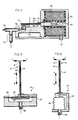
- Figure 1 is a perspective view illustrating a flexure or bender device according to one embodiment of the invention;
- Figure 2 is a schematic view illustrating a magnetostrictive electromechanical transducer utilizing the flexure device of Figure 1 in one operating position;
- Figure 3 illustrates the magnetostrictive electromechanical transducer of Figure 2 with the flexure device in a second operating position;
- Figure 4 illustrates an alternative electromechanical transducer embodiment;
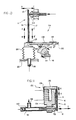
- Figures 5-9 illustrate alternative applications utilizing the flexure device of Figure 1;
- Figure 10 illustrates an alternative flexure or bender device according to another embodiment; and
- Figure 11 illustrates another alternative application utilizing the flexure device of Figure 1.
- Referring now to Figure 1, there is illustrated a flexure element constructed as a first embodiment of the present invention. Flexure or
bender element 10 is formed of metal, plastic, fiber or other similarly rigid material into a member with closedend 12 andrespective legs End 18 ofleg 14 is fixed in position such as schematically illustrated by afixed mounting block 20 to aground reference 22.End 24 ofopposite leg 16 is mounted to amovable member 26 which can be a part of or connected to a magnetostrictive, electrostrictive or piezoelectric device or to a force or pressure element providing very small, micron-sized longitudinal displacements ofleg 16. - It is to be understood that these types of movable members are given as examples, so that neither the type of movable member, the size of the flexure element, nor the amount of flexure element movement is to be taken as a limitation of the present invention.
- Thus, for example, a magnetostrictive device or a bellows formed as
movable member 26 can generate linear micro-displacements ofleg 16 in the directions indicated byreference arrow 28. As one example, if a magnetostrictive member or a bellows formed asmovable member 26 movesleg 16 in a linear displacement in direction A shown with respect toreference arrow 28,flexural element 10 will bend so that closedfree end 12 will be displaced downwardly as indicated by direction C ofreference arrow 30. Conversely, micro-motions ofleg 16 in direction B ofreference arrow 28 will bend freeclosed end 12 upwardly in direction D ofreference arrow 32. Linear longitudinal displacements ofleg 16 are therefore translated in amplified transverse displacements ofclosed end 12. - As shown in Figure 1, micro-motions of
leg 16 along longitudinal axis X are translated into larger motions of free,closed end 12 along the transverse axis Z. Motions of micron dimensions ofleg 16 can result in 100-1000 microns movement ofclosed end 12 along axis Z. As an example of one embodiment of the present invention,flexural element 10 was constructed of type 304 stainless steel material having the following dimensions: flexure leg length - 50.04 mm; flexure leg width - 5.64 mm; each leg thickness - 0.381 mm; and the legs being substantially adjacent each other over their length. With micro-motion displacement ofleg 16 along longitudinal axis X amounting to 0.0254 mm, a corresponding translated displacement of freeclosed end 12 along transverse axis Z of 0.762 mm was obtained, thereby providing an amplification ratio of 30/l. - Rather than type 304 stainless steel, any other rigid type material with linear elastic characteristics may be utilized. Also, increasing the gap between
legs - Accordingly, if a magnetostrictive element which is a high force, very small motion causing device is used as the primary motion displacement means for a flexure leg, it would be advantageous to utilize a smaller gap between
legs legs - Referring to Figures 2, 3, there is illustrated an electromechanical transducer in the form of a current to pressure
transducer 40 including a flexure orbender element 10 as in Figure 1.Transducer housing 42 includes anenclosed nozzle chamber 44 for containing fluid under pressure supplied through aninlet port 46 containing aprimary restrictor 48. Anoutlet port 50 communicates withnozzle chamber 44 to provide a fluid output pressure fromtransducer 40. - A
nozzle 52 is mounted inhousing 42 with acontrol nozzle end 54 extending withinnozzle chamber 44 and with anexhaust nozzle end 56 communicatingnozzle chamber 44 with anexhaust port 58. -
Flexure element 10 is cantilever mounted innozzle chamber 44 with freeclosed end 12 above the control nozzle end. In particular,flexure element leg 14 is fixedly mounted to anabutment 60 to maintainflexure element 10 in the position shown in Figure 2.Leg 16 is connected to a movablemagnetic core 62 at one end and with the other end ofcore 62 being connected to amagnetostrictive rod 64 which in turn has its opposite end mounted tomagnetic housing 66. - Within
magnetic housing 66, there is included acoil 68 surroundingmagnetostrictive rod 64 with the opposite coil ends connected to respective connectingwires 70 for receiving an electrical current.Magnetostrictive rod 64 can be formed of magnetostrictive material which responds to a magnetic field produced by current flowing incoil 68 to induce a strain in the magnetostrictive material and thereby elongate the material. - Such magnetostrictive material is well known and is normally formed of alloys of rare earth elements with iron. Presently available rare earth magnetostrictive materials produce large strains up to approximately 2,000 ppm (parts per million) for an imposed magnetic field as a result of a current in surrounding
coil 68. In particular, it is preferred thatrod 64 be formed of a magnetostrictive material sold with the trademark "TERFENOL-D", which is currently available from Edge Technologies, Inc. of Ames, Iowa. - One end of
nozzle chamber 44 is sealed by means of aflexible feedback diaphragm 72 which in turn is mounted to movablemagnetic core 62. Thus,enclosed nozzle chamber 44 withinhousing 42 has openings throughinlet port 46,outlet port 50 andexhaust port 58 and is sealed at the opposite end by means of aflexible diaphragm 72. The outer perimeter ofdiaphragm 72 is mounted tohousing 42 and the inner perimeter is mounted into movablemagnetic core 62.Feedback diaphragm 72 may be constructed of a thin metal material such as type 316 stainless steel. -
Electromechanical transducer 40 transforms electrical energy in the form of an electrical current supplied towires 70 into mechanical energy in the form of fluid pressure supplied fromfluid outlet port 50. Such a transducer is particularly useful in for instance an electronic control loop where the final control element, generally a control valve, is pneumatically operated. Typically, the transducer receives a milliampere of direct current input signal such as onwires 70 and transmits a proportional pneumatic output pressure onoutput port 50 to a final control element which may control the flow of fluid in a fluid pipeline system. - In the operation of the present invention illustrated in Figures 2, 3, an electrical current supplied to
wires 70 and flowing incoil 68 produces a magnetostrictive strain in the magnetostrictive material formingmagnetostrictive rod 64 so as to elongaterod 64 and transmit this micro-motion throughfeedback diaphragm 72 and movablemagnetic core 62 toleg 16 ofbender 10. This linear micro-motion displacement ofleg 16 causes freeclosed end 12 of the flexure element to move towardcontrol nozzle end 54 with a greatly amplified motion as shown in Figure 3. - As
flexure element 10 moves towardnozzle 52, the fluid flow outexhaust nozzle end 56 andexhaust port 58 is restricted thereby resulting in an increase in fluid pressure innozzle chamber 44. The increased nozzle pressure innozzle chamber 44 acts onfeedback diaphragm 72 to result in a compressive force which tends to restorerod 64 to its original position. For reference purposes, Figure 3 shows an exaggerated illustration of the micro-movement x ofleg 16. The feedback compression againstdiaphragm 72 continues until the feedback force balances the electrical input force inducing the movement ofmagnetostrictive rod 64 to thereby establish an output pressure onfluid output port 50 which is proportional to the input current. Thus, bending offlexure element 10 towards or away from control nozzle end 54 changes the fluid output pressure onfluid output port 50 so as to change the pressure innozzle chamber 44 acting againstfeedback diaphragm 72 and to change the resulting feedback force until the final fluid output pressure atport 50 is proportional to the electrical current value present atwires 70. - An alternative current to pressure transducer is shown in Figure 4 wherein the prior feedback on
diaphragm 72 has been eliminated. In the embodiment of Figure 4, the supply pressure is coupled to a T-fitting 74 through a primary restrictor 76 and communicates withoutput line 78. In this embodiment the output pressure online 78 is directly responsive to the input current value atwires 70. The output pressure in this case is more sensitive to the input, but, without feedback, is less linear and less precise compared to the current to pressure transducer of Figures 2, 3. - It is understood of course that in the illustrated bender element embodiment of Figure 1, either
leg flexure element 10 of the present invention is particularly useful when small, micron-sized displacements are generated by magnetostrictive, electrostrictive or piezoelectric devices. Such combinations find practical application in actuators and transducers, such as current to pressure transducers, electro-pneumatic relays, and control valve actuators. - Alternatively, both legs may be movable with respect to each other. Thus, for instance, if both legs are moved in the same direction there is no transverse displacement of the closed end; and if both legs are moved in opposite directions the closed end will be displaced in a transverse direction with amplified movement. Such a device may be utilized as a motion averaging or summing transducer unit wherein first and second inputs can be coupled to a respective leg and the input displacements generate amplified transverse movements of the free closed end corresponding to the difference between the two inputs.
- Other application embodiments of a flexure or bender element in accordance with this aspect of the invention are illustrated in Figures 5-11. Figures 5-8 and 11 illustrate a flexure element in various applications using the motion amplification and translation features of such a flexure element; Figure 9 illustrates a flexure element to attenuate large motions and provide precise smaller motions for positioning of surfaces or probes; and Figure 10 illustrates a flexure element embodiment used to sum pressure and motion inputs.
- Figure 5 illustrates an
embodiment 79 having flexure orbender 10 with fixedleg 14 mounted to a stationery member such as fixed mountingblock 20, and with movingleg 16 coupled to adiaphragm 80 through a connectingflange 82. The diaphragm is mounted inblock 20 so as to provide anenclosed pressure chamber 84 receiving an input fluid pressure through aninlet 86. The pressure atinlet 86 and inchamber 84 acts ondiaphragm 80 to moveleg 16 in directions A or B to provide motion amplification and translation along respective directions C or D. Thus, the bender embodiment of Figure 5 converts pressure to motion using a single diaphragm. - Figure 6 illustrates another
bender application embodiment 87 in which the bender element converts pressure to motion using abellows 88 to which is coupled a fluid pressure throughinlet 86. Figure 7 illustrates anotherbender embodiment 89 which is responsive to both input fluid pressure oninlet 86 and input fluid pressure oninlet 90 and converts the output motion along respective directions C, D using a diaphragm stack. A firstenclosed chamber 84 in fixedmounting block 20 is provided bydiaphragm 80. Asecond chamber 92 is provided bydiaphragm 94 whereinfluid pressure inlet 90 communicates withchamber 92. - Figure 8 illustrates another
embodiment 96 in which a flexure orbender element 10 is used to operate aspool valve 98.Fixed leg 14 is mounted to fixedmounting block 20 and movingleg 16 is connected through a suitable drive means to cause motion displacements along directions A,B. Closed end 12 is mounted tovalve rod 100 to thereby move the valve members 101 along directions C, D in response to input motions A, B.Operating valve rod 100 along motion directions C, D, respectively couples the supply pressure inspool valve 98 to output pressure 1 or output pressure 2. - The flexure
element application embodiment 102 of Figure 9 provides motion attenuation rather than motion amplification.Fixed leg 14 is again mounted to a fixedmounting block 20.Movable leg 16 is mounted to afree end 103 of aflexible member 105 having theopposite end 107 fixed in position by mounting to a fixedmounting block 20. Typically, flexing or pivotingend 103 would include a special surface, probe, switch elements, or other devices utilizing the small output displacement in directions A, B ofend 103 in response to large motion inputs in directions C, D at flexure element closedend 12. Accordingly, in this aspect of the invention, abender element 10 is used to provide precise motion attenuation for precise positioning of laser mirrors, etc. on movingend 103. - Referring now to Figure 10, there is illustrated an
alternative application embodiment 104 using a bender element 11 withlegs D. Moving leg 16 is mounted tobellows 88 receiving fluid pressure throughinlet line 86. Longitudinal displacements along directions A, B are therefore in direct response to the pressure atinlet line 86.Movable leg 17 also may be displaced longitudinally along directions A′, B′ in response to a drive motion means connected to end 23 ofleg 17. Thus, flexure element closedend 12 moves in directions C, D in response to the difference between the motion inputs tolegs - For example, if the
legs closed end 12 moves in amplified transverse direction C. If the legs are moved in directions A′, B,closed end 12 moves in direction D. If the legs are moved in respective directions A, A′ or B, B′,closed end 12 does not move in the transverse direction. - In the example of
embodiment 104 shown in Figure 10,leg 17 is displaced by means of the movements of aplatform 106 having arotating wheel 108 in contact withcam surface 110 of aneccentric cam 112.Eccentric cam 112 is fixed to and driven by arotatable shaft 114 which is rotatably mounted in a fixedframe 116. Thus, asshaft 114 is rotated in the indicated clockwise or counter-clockwise directions,eccentric cam 12 is rotated to moveplate 106 upwardly or downwardly, thereby providing the displacement motions ofleg 17 along directions A′, B′. Ahinge member 118 may be used to connectplate 106 to a fixedframe 120. -
Nozzle 122 is mounted adjacentclosed end 12 and is supplied with a fluid flow. thus, the fluid flow and pressure atnozzle 122 is controlled by the movement ofclosed end 12 in directions C, D. In the illustration ofembodiment 104 shown in Figure 10, bender element 11 is responsive to the pressure atinput 86 and the motion input onshaft 114.Embodiment 104 therefore has applications in the construction of process controllers and valve positioners. - Figure 11 illustrates another
embodiment 130 comprising a proportional solenoid current to pressure transducer.Embodiment 130 includes abender element 10 for converting an electric current into a variable flow rate fromnozzle outlet 132 using asolenoid 134.Fixed leg 14 is mounted to a rigid, fixed portion ofsolenoid 134.Displaceable leg 16 is mounted to a free end ofsolenoid armature 136 with the other end being hingedly mounted to the solenoid by hinge means 138. A source of pneumatic pressure is coupled to a T-fitting 140 through a fixed metering orifice orprimary restrictor 142 and communicates withoutput line 146. - In operation, the proportional current to pressure transducer makes use of the
flexure 10 to minimize the amount of travel required of the solenoid's armature. Reduced armature travel allows the solenoid to be designed to operate in a stable region and therefore act in a proportional manner in response to changes in electrical current rather than the snap acting manner commonly associated with solenoid operation. Thesolenoid armature 136 slowly moves towards and away from thesolenoid 134 in response to the input solenoid coil current due to the stiffness ofelement 10. These small motion displacements along directions A, B are translated into amplified displacements C, D ofclosed end 12 to provide a variable flow rate fromnozzle 132. This embodiment eliminates the hysteresis due to pivots, bearings, etc. commonly encountered in other transducer designs.
Claims (23)
- A mechanical flexure element useful for motion amplification comprising:
a flexure element (10, 11) formed of a rigid material having a closed end (12) and two legs (16, 17) extending therefrom along respective longitudinal axes;
characterized bymotion displacement means (26, 64, 88) for displaceably moving one leg (16) with respect to the other (17) in longitudinal displacement,said longitudinal displacement being amplified and translated into a larger transverse displacement (z) of said closed end (12) with respect to said longitudinal axes (x). - A mechanical flexure element according to Claim 1, wherein said motion displacement means includes respective motion means (88, 112) for moving each leg (16, 17) with respect to the other in micrometer-sized longitudinal displacements.
- A mechanical flexure element according to Claim 1, wherein said motion displacement means includes respective motion means (88, 112) for moving each leg (16, 17) with respect to the other in micrometer-sized longitudinal displacements to enable said larger transverse displacements (z) which are the difference between said respective motion means (88, 112),
- A mechanical flexure element according to Claim 1, wherein means (20) are provided for fixedly mounting one (14) of said legs; and said motion displacement means (26) are alternatively provided for displaceably moving said closed end (12) in micrometer-sized displaceable motions transverse (7) to said longitudinal axes (x);
wherein said transverse micrometer-sized displaceable motions are attenuated and translated into smaller micrometer-sized longitudinal displacement of the other (16) of said legs. - A mechanical flexure element according to Claim 1, wherein means (20) are provided for fixedly mounting one (14) of said legs; and said motion displacement means (26) are coupled to the other (16) of said legs for displaceably moving the other (16) of said legs along its longitudinal axis (x) to enable the flexure element (10) to selectively bend towards or away from said longitudinal axis (x),
said longitudinal displacement movement (A, B) of said other leg (16) being amplified and translated into larger transverse movement (C,D) of said closed end (12) with respect to said longitudinal axis (x). - A mechanical flexure element according to Claim 5, wherein said motion displacement means (26) comprises pressure means including an input fluid pressure (86) for displaceably moving the other (16) of said legs in response to said input fluid pressure.
- A mechanical flexure element according to Claim 6, wherein said pressure means includes diaphragm means (80, 82) including a diaphragm (80) connected to the other (16) of said legs to displaceably move said leg (16) in response to said input fluid pressure (86) acting on said diaphragm (80).
- A mechanical flexure element according to Claim 7, wherein said pressure means includes a second diaphragm (94) connected to the other of said legs (16) and further includes a second input fluid pressure (90) and wherein said other (16) of said legs is displaceably moved in response to the two input fluid pressures (86, 90).
- A mechanical flexure element according to Claim 6, wherein said pressure means includes bellows means (88) including a bellows connected to the other (16) of said legs to displaceably move said leg (16) in response to said input fluid pressure (86) acting on said bellows.
- A mechanical flexure element according to Claim 5, wherein said motion displacement means (26) comprises an electromechanical transducer element.
- A mechanical flexure element according to Claim 10, wherein said electromechanical transducer element comprises a magnetostrictive element (64).
- A mechanical flexure element according to Claim 5, wherein said motion displacement means comprises solenoid means (134, 136) including a solenoid coil (134), a solenoid armature (136) movable in response to electrical current supplied to the solenoid coil, and means mounting the solenoid armature (136) to the other (16) of said legs to displaceably move said other leg (16) in response to said electrical current.
- A mechanical flexure element according to Claim 5, wherein said flexure element (10) has a U-shaped configuration.
- An electromechanical transducer providing a fluid output pressure proportional to an electrical input signal comprising:an enclosed chamber (44) for containing a fluid under pressure;a restricted fluid inlet port (46) to said enclosed chamber (44);a fluid outlet port (50) from said enclosed chamber (44) for providing said fluid output pressure;a nozzle (52) coupled to said enclosed chamber (44) having a control nozzle end (54) within said chamber and an exhaust nozzle end (56) extending beyond said chamber (44);a flexure element (10) according to any one of the Claims 1 to 5 having its closed end (12) and two legs (14, 16) extending therefrom supported within the enclosed chamber (44) with the closed end (12) immediately above the control nozzle end (54);movable means (62, 64) connected to one (16) of the flexure element legs for moving said one leg (16) with respect to the other leg (14) and enabling the flexure element (10) to selectively bend towards or away from said control nozzle end (54), said movable means including;1) electrical drive means (68) for responding to said electrical input signal and actuating said movable means (62, 64); and2) diaphragm means (72) including a feedback diaphragm forming a portion of said enclosed chamber (44) for enabling said fluid under pressure in said chamber to act against said diaphragm (72) and provide a feedback force;whereby bending of the flexure element (10) towards or away from said control nozzle end (54) changes the fluid output pressure from said fluid outlet port (50) to change the pressure in said chamber (44) acting against said diaphragm (72) and the resulting feedback force until the final fluid output pressure is proportional to the electrical input signal.
- An electromechanical transducer according to Claim 14, wherein said movable means includes a magnetostrictive element (64).
- An electromechanical transducer according to Claim 15, wherein said movable means includes a magnetic core (62) connected intermediate the flexure element (10) and the magnetostrictive element (64).
- An electromechanical transducer according to Claim 16, wherein said electrical drive means includes a coil (68) surrounding said magnetostrictive element (64) and having an input (70) for receiving said electrical input signal.
- An electromechanical transducer according to Claim 14, wherein said flexure element (10) is cantilever mounted by its legs (14, 16) within said enclosed chamber (44) with the free closed end (12) extending in said chamber (44) and disposed above said control nozzle end (54).
- An electromechanical transducer according to Claim 18, wherein said flexure element (10) is U-shaped.
- An electromechanical transducer providing a fluid output pressure proportional to an electrical input signal comprising:fluid pressure input (74) and output (78) ports;nozzle means (52) including a nozzle with a control nozzle end (54) and a nozzle inlet (56) communicating between said fluid pressure input and output ports (74, 78);a flexure element (10) according to any one of the Claims 1 to 5 having a closed end (12) and two legs (14, 16) extending therefrom with the closed end immediately above the control nozzle end (54);motion displacement means (62, 64, 68) coupled to one (16) of the U-shaped flexure element legs for moving said one leg (16) with respect to the other leg (14) and enabling the flexure element to selectively bend towards or away from said control nozzle end (54), said motion displacement means including electrical drive means (68) for responding to said electrical input signal and actuating said motion displacement means;said bending of the flexure element (10) towards or away from said control nozzle end (54) changes the fluid output pressure from said fluid output port (78) responsive to changes in said electrical input signal.
- A pressure transducer for translating linear displacements into corresponding control pressure changes comprising:a control valve (98) including at least one outlet port (P1, P2) for supplying an output pressure, an inlet port (Pin) for coupling to a supply pressure, and a movable valve control member (101) including valve means for selectively interconnecting said inlet port (Pin) and said outlet port (P1, P2) to couple said supply pressure to said outlet port in response to controlled movement of said valve control member (101);a flexure element (10) according to any one of the Claims 1 to 5 having a closed end (12) and two legs (14, 16) extending therefrom along respective longitudinal axes, including means for mounting one of said legs (14, 16) to said movable valve control member (101); andmeans for providing relative longitudinal movement of said legs (14, 16) to enable the flexure element (10) to bend for controllably moving said valve control member (101) and thereby controlling the coupling of said supply pressure to said outlet (P1, P2).
- A pressure transducer according to Claim 21, including means mounting said movable valve control member (101) to one of said legs (14, 16) adjacent said closed end (12).
- A pressure transducer according to Claim 21, wherein said control valve (98) comprises a spool valve.
Applications Claiming Priority (2)
| Application Number | Priority Date | Filing Date | Title |
|---|---|---|---|
| US55433990A | 1990-07-19 | 1990-07-19 | |
| US554339 | 1990-07-19 |
Publications (3)
| Publication Number | Publication Date |
|---|---|
| EP0467873A2 EP0467873A2 (en) | 1992-01-22 |
| EP0467873A3 EP0467873A3 (en) | 1993-09-22 |
| EP0467873B1 true EP0467873B1 (en) | 1997-01-15 |
Family
ID=24212974
Family Applications (1)
| Application Number | Title | Priority Date | Filing Date |
|---|---|---|---|
| EP91870112A Expired - Lifetime EP0467873B1 (en) | 1990-07-19 | 1991-07-18 | Mechanical flexure for motion amplification and transducer with same |
Country Status (5)
| Country | Link |
|---|---|
| US (3) | US5163463A (en) |
| EP (1) | EP0467873B1 (en) |
| JP (1) | JP3184254B2 (en) |
| BR (1) | BR9103087A (en) |
| DE (1) | DE69124157T2 (en) |
Families Citing this family (31)
| Publication number | Priority date | Publication date | Assignee | Title |
|---|---|---|---|---|
| AT396392B (en) | 1991-09-30 | 1993-08-25 | Hoerbiger Fluidtechnik Gmbh | PIEZO VALVE |
| US5207737A (en) * | 1992-02-27 | 1993-05-04 | Landis & Gyr Powers, Inc. | Analog output electro-pneumatic transducer |
| DE4320909C1 (en) * | 1993-06-18 | 1994-06-01 | Siemens Ag | Servo valve operating between inlet and outlet air nozzles - uses flexible beam held at one end in adjustable braked liner |
| US5460202A (en) * | 1993-11-22 | 1995-10-24 | Landis & Gyr Powers, Inc. | Three-way piezoelectric valve |
| US5868375A (en) * | 1995-10-11 | 1999-02-09 | Marotta Scientific Controls, Inc. | Magnetostrictively actuated valve |
| US6026847A (en) * | 1995-10-11 | 2000-02-22 | Reinicke; Robert H. | Magnetostrictively actuated valve |
| SE9600913L (en) * | 1996-03-08 | 1997-02-03 | Siemens Elema Ab | Valve |
| US6035878A (en) * | 1997-09-22 | 2000-03-14 | Fisher Controls International, Inc. | Diagnostic device and method for pressure regulator |
| US6056008A (en) * | 1997-09-22 | 2000-05-02 | Fisher Controls International, Inc. | Intelligent pressure regulator |
| GB2348538B (en) * | 1997-12-15 | 2002-04-17 | Mitsubishi Electric Corp | Microactuator |
| DE19931990C1 (en) * | 1999-07-09 | 2001-01-11 | Festo Ag & Co | Solenoid valve |
| US6279842B1 (en) | 2000-02-29 | 2001-08-28 | Rodi Power Systems, Inc. | Magnetostrictively actuated fuel injector |
| US20030107013A1 (en) * | 2001-12-12 | 2003-06-12 | Alfred Pappo | Variable valve with an electromagnetically-elongated actuator |
| US6918569B2 (en) * | 2002-02-28 | 2005-07-19 | Jansen's Aircraft Systems Controls, Inc. | Active combustion fuel valve |
| US6981518B2 (en) * | 2002-03-15 | 2006-01-03 | Cytonome, Inc. | Latching micro-regulator |
| EP1353102B1 (en) * | 2002-04-12 | 2009-06-24 | Seiko Epson Corporation | Valve device |
| ATE271670T1 (en) * | 2002-05-31 | 2004-08-15 | Festo Ag & Co | PIEZO VALVE |
| DE20212649U1 (en) | 2002-08-17 | 2002-10-10 | FESTO AG & Co., 73734 Esslingen | Multi-way valve |
| US7478559B2 (en) * | 2003-12-04 | 2009-01-20 | National University Of Singapore | Capacitive pressure sensor with a cantilever member |
| DE202005021271U1 (en) * | 2004-03-30 | 2007-09-27 | Bühner, Kurt | By means of the inverse piezo effect actuated drive |
| FR2873828B1 (en) * | 2004-07-27 | 2006-10-20 | In Lhc Soc Par Actions Simplif | PRESSURE CONTROL SERVOVALVE WITH REDUCED LEAKAGE RATE |
| US7849870B2 (en) * | 2007-11-01 | 2010-12-14 | Honeywell International Inc. | Piezoelectric pressure control valve |
| US20100148100A1 (en) * | 2008-12-17 | 2010-06-17 | Parker Hannifin Corporation | Media isolated piezo valve |
| GB0918602D0 (en) * | 2009-10-23 | 2009-12-09 | Rolls Royce Plc | Displacement amplifier |
| CN103145087B (en) * | 2013-03-14 | 2015-09-09 | 南昌工程学院 | The magnetostriction type composite cantilever that Terfenol-D thin slice drives |
| DE102014101542A1 (en) * | 2014-02-07 | 2015-08-13 | Marco Systemanalyse Und Entwicklung Gmbh | Pneumatic valve and valve unit |
| WO2015153179A1 (en) * | 2014-04-01 | 2015-10-08 | Agiltron, Inc. | Microelectromechanical displacement structure and method for controlling displacement |
| US10724878B2 (en) | 2015-10-30 | 2020-07-28 | Fisher Controls International Llc | Methods and apparatus to correct remote sensor signals |
| CN110940365B (en) * | 2019-12-10 | 2020-10-30 | 北京理工大学 | Mechanical amplification structure for increasing sensitivity of interference type optical fiber sensor |
| US11781669B1 (en) * | 2022-05-12 | 2023-10-10 | Tangtring Seating Technology Inc. | Air valve |
| US11982369B2 (en) * | 2022-06-01 | 2024-05-14 | Tangtring Seating Technology Inc | Air valve structure |
Family Cites Families (26)
| Publication number | Priority date | Publication date | Assignee | Title |
|---|---|---|---|---|
| US2018384A (en) * | 1933-09-14 | 1935-10-22 | Western Electric Co | Gauge |
| US2139251A (en) * | 1937-03-01 | 1938-12-06 | Sheffield Gage Corp | Measuring instrument |
| US2177398A (en) * | 1938-03-10 | 1939-10-24 | Sheffield Gage Corp | Motion transmitting mechanism |
| US2419061A (en) * | 1944-09-22 | 1947-04-15 | Baldwin Locomotive Works | Pressure operated electric strain gage |
| US2769867A (en) * | 1947-02-07 | 1956-11-06 | Sonotone Corp | Dielectrostrictive signal and energy transducers |
| US2778232A (en) * | 1952-09-24 | 1957-01-22 | Time Inc | Precision carriage displacement device |
| US2887294A (en) * | 1955-12-29 | 1959-05-19 | High Voltage Engineering Corp | Gas leak |
| US2904735A (en) * | 1956-01-17 | 1959-09-15 | Kelvin & Hughes Ltd | Force responsive servosystem |
| US2963904A (en) * | 1957-06-14 | 1960-12-13 | Sr William C Dillon | Dynamometer |
| US3024648A (en) * | 1958-11-03 | 1962-03-13 | Webster Instr Inc | Double beam force measuring instrument |
| US2992373A (en) * | 1958-12-15 | 1961-07-11 | Toledo Scale Corp | Electrical displacement measuring servosystem |
| US3218445A (en) * | 1962-01-29 | 1965-11-16 | Phillips Petroleum Co | Signal multiplier where one signal to be multiplied causes a member to deform |
| US3151693A (en) * | 1962-04-03 | 1964-10-06 | Chapman Everett | Weighing devices |
| US3174716A (en) * | 1962-10-15 | 1965-03-23 | Salter Jack Nelson | Magnetostrictive multiplier device |
| US3370458A (en) * | 1965-09-10 | 1968-02-27 | W C Dillon & Company Inc | Mechanical force gauge |
| US3414010A (en) * | 1965-11-01 | 1968-12-03 | Honeywell Inc | Control apparatus |
| US3638481A (en) * | 1969-03-04 | 1972-02-01 | Becton Dickinson Co | Pressure sensor |
| US3848462A (en) * | 1973-06-29 | 1974-11-19 | W Mcilrath | Strain control transducer |
| US4025942A (en) * | 1974-03-18 | 1977-05-24 | Kulite Semiconductor Products, Inc. | Low pressure transducers employing large silicon diaphragms having non-critical electrical properties |
| US4158368A (en) * | 1976-05-12 | 1979-06-19 | The United States Of America As Represented By The Secretary Of The Navy | Magnetostrictive transducer |
| DE2710144A1 (en) * | 1977-03-09 | 1978-09-14 | Gerdts Gustav F Kg | Pressure threshold reacting monitor - has pivoting sensor plate with preset bias spring to determine operating threshold |
| US4340083A (en) * | 1978-11-30 | 1982-07-20 | Carleton Controls Corporation | Deflectable beam valve |
| CH670310A5 (en) * | 1985-04-17 | 1989-05-31 | Kristal Instr Ag | |
| DE3678063D1 (en) * | 1985-08-08 | 1991-04-18 | Hottinger Messtechnik Baldwin | STRETCH SENSOR. |
| JPH02138501A (en) * | 1988-11-17 | 1990-05-28 | Smc Corp | Nozzle flapper mechanism |
| US4926896A (en) * | 1988-12-23 | 1990-05-22 | Dresser Industries, Inc. | Sensitive electrical to mechanical transducer |
-
1991
- 1991-06-26 US US07/723,698 patent/US5163463A/en not_active Expired - Lifetime
- 1991-07-16 JP JP19991891A patent/JP3184254B2/en not_active Expired - Lifetime
- 1991-07-18 BR BR919103087A patent/BR9103087A/en not_active IP Right Cessation
- 1991-07-18 EP EP91870112A patent/EP0467873B1/en not_active Expired - Lifetime
- 1991-07-18 DE DE69124157T patent/DE69124157T2/en not_active Expired - Lifetime
-
1992
- 1992-05-19 US US07/885,534 patent/US5265637A/en not_active Expired - Lifetime
-
1993
- 1993-09-27 US US08/127,196 patent/US5381817A/en not_active Expired - Lifetime
Also Published As
| Publication number | Publication date |
|---|---|
| US5381817A (en) | 1995-01-17 |
| DE69124157T2 (en) | 1997-08-21 |
| US5163463A (en) | 1992-11-17 |
| DE69124157D1 (en) | 1997-02-27 |
| JP3184254B2 (en) | 2001-07-09 |
| EP0467873A3 (en) | 1993-09-22 |
| JPH0688760A (en) | 1994-03-29 |
| US5265637A (en) | 1993-11-30 |
| EP0467873A2 (en) | 1992-01-22 |
| BR9103087A (en) | 1992-04-28 |
Similar Documents
| Publication | Publication Date | Title |
|---|---|---|
| US5381817A (en) | Mechanical flexure for motion amplification and transducer with same | |
| US6230731B1 (en) | Valve closure seating method and apparatus | |
| CA1157928A (en) | Current to pressure converter apparatus | |
| CN109249416B (en) | Micro clamp with clamping jaw being fiber Bragg grating and clamping force self-sensing function | |
| JPH0335521B2 (en) | ||
| US5701043A (en) | High resolution actuator | |
| US5249117A (en) | Adaptive control systems | |
| JP2001141091A (en) | Flow rate control valve | |
| US2996072A (en) | Actuator | |
| US3587617A (en) | Fluid control apparatus | |
| EP0394582B1 (en) | Magnetostrictive actuator using adaptive control. | |
| JPH0336768Y2 (en) | ||
| JPS62215176A (en) | Three-way valve | |
| JPS6242217Y2 (en) | ||
| US5179887A (en) | Captive cylinder linear solenoid valve positioner | |
| EP0031937B1 (en) | An electro-pneumatic or electro-hydraulic transducer | |
| JP3267662B2 (en) | Direct drive servo valve | |
| JP2587392Y2 (en) | Pneumatic instrument | |
| JPH0422083Y2 (en) | ||
| JPH04203501A (en) | Electropneumatic converting mechanism | |
| JPH0763679B2 (en) | Electro-hydraulic actuator | |
| SU233998A1 (en) | ELECTROPNEUMATIC POSITIONER | |
| JPS63199978A (en) | Mass flow controller | |
| CA1151897A (en) | Force transducer | |
| JPH0440002Y2 (en) |
Legal Events
| Date | Code | Title | Description |
|---|---|---|---|
| PUAI | Public reference made under article 153(3) epc to a published international application that has entered the european phase |
Free format text: ORIGINAL CODE: 0009012 |
|
| AK | Designated contracting states |
Kind code of ref document: A2 Designated state(s): DE FR GB |
|
| PUAL | Search report despatched |
Free format text: ORIGINAL CODE: 0009013 |
|
| AK | Designated contracting states |
Kind code of ref document: A3 Designated state(s): DE FR GB |
|
| 17P | Request for examination filed |
Effective date: 19931209 |
|
| 17Q | First examination report despatched |
Effective date: 19940823 |
|
| GRAG | Despatch of communication of intention to grant |
Free format text: ORIGINAL CODE: EPIDOS AGRA |
|
| GRAH | Despatch of communication of intention to grant a patent |
Free format text: ORIGINAL CODE: EPIDOS IGRA |
|
| GRAH | Despatch of communication of intention to grant a patent |
Free format text: ORIGINAL CODE: EPIDOS IGRA |
|
| GRAA | (expected) grant |
Free format text: ORIGINAL CODE: 0009210 |
|
| AK | Designated contracting states |
Kind code of ref document: B1 Designated state(s): DE FR GB |
|
| ET | Fr: translation filed | ||
| REF | Corresponds to: |
Ref document number: 69124157 Country of ref document: DE Date of ref document: 19970227 |
|
| PLBE | No opposition filed within time limit |
Free format text: ORIGINAL CODE: 0009261 |
|
| STAA | Information on the status of an ep patent application or granted ep patent |
Free format text: STATUS: NO OPPOSITION FILED WITHIN TIME LIMIT |
|
| 26N | No opposition filed | ||
| REG | Reference to a national code |
Ref country code: GB Ref legal event code: IF02 |
|
| REG | Reference to a national code |
Ref country code: FR Ref legal event code: CA Ref country code: FR Ref legal event code: CD |
|
| PGFP | Annual fee paid to national office [announced via postgrant information from national office to epo] |
Ref country code: DE Payment date: 20100714 Year of fee payment: 20 Ref country code: FR Payment date: 20100805 Year of fee payment: 20 |
|
| PGFP | Annual fee paid to national office [announced via postgrant information from national office to epo] |
Ref country code: GB Payment date: 20100714 Year of fee payment: 20 |
|
| REG | Reference to a national code |
Ref country code: DE Ref legal event code: R071 Ref document number: 69124157 Country of ref document: DE |
|
| REG | Reference to a national code |
Ref country code: DE Ref legal event code: R071 Ref document number: 69124157 Country of ref document: DE |
|
| REG | Reference to a national code |
Ref country code: GB Ref legal event code: PE20 Expiry date: 20110717 |
|
| PG25 | Lapsed in a contracting state [announced via postgrant information from national office to epo] |
Ref country code: GB Free format text: LAPSE BECAUSE OF EXPIRATION OF PROTECTION Effective date: 20110717 |
|
| PG25 | Lapsed in a contracting state [announced via postgrant information from national office to epo] |
Ref country code: DE Free format text: LAPSE BECAUSE OF EXPIRATION OF PROTECTION Effective date: 20110719 |