EP0467704B1 - Rotor synchronized cross polarization of solid state NMR - Google Patents
Rotor synchronized cross polarization of solid state NMR Download PDFInfo
- Publication number
- EP0467704B1 EP0467704B1 EP91306605A EP91306605A EP0467704B1 EP 0467704 B1 EP0467704 B1 EP 0467704B1 EP 91306605 A EP91306605 A EP 91306605A EP 91306605 A EP91306605 A EP 91306605A EP 0467704 B1 EP0467704 B1 EP 0467704B1
- Authority
- EP
- European Patent Office
- Prior art keywords
- sample
- modulation
- spinning
- nuclear spins
- cross
- Prior art date
- Legal status (The legal status is an assumption and is not a legal conclusion. Google has not performed a legal analysis and makes no representation as to the accuracy of the status listed.)
- Expired - Lifetime
Links
- 238000005388 cross polarization Methods 0.000 title claims description 17
- 230000001360 synchronised effect Effects 0.000 title claims description 17
- 238000000371 solid-state nuclear magnetic resonance spectroscopy Methods 0.000 title 1
- 238000009987 spinning Methods 0.000 claims description 21
- 238000005481 NMR spectroscopy Methods 0.000 claims description 12
- 238000001208 nuclear magnetic resonance pulse sequence Methods 0.000 claims description 8
- 238000000034 method Methods 0.000 claims description 6
- 230000003068 static effect Effects 0.000 claims description 5
- 230000003534 oscillatory effect Effects 0.000 claims description 3
- 230000001747 exhibiting effect Effects 0.000 claims description 2
- 238000006073 displacement reaction Methods 0.000 claims 2
- 230000036962 time dependent Effects 0.000 claims 2
- 239000000523 sample Substances 0.000 description 24
- 238000001228 spectrum Methods 0.000 description 11
- 230000005284 excitation Effects 0.000 description 6
- 230000005855 radiation Effects 0.000 description 6
- 238000002474 experimental method Methods 0.000 description 5
- 230000005415 magnetization Effects 0.000 description 5
- 230000008901 benefit Effects 0.000 description 4
- 238000005259 measurement Methods 0.000 description 4
- 238000013459 approach Methods 0.000 description 3
- 238000005384 cross polarization magic-angle spinning Methods 0.000 description 3
- 238000012546 transfer Methods 0.000 description 3
- 230000000694 effects Effects 0.000 description 2
- 230000006872 improvement Effects 0.000 description 2
- 239000000843 powder Substances 0.000 description 2
- 238000012935 Averaging Methods 0.000 description 1
- 239000013256 coordination polymer Substances 0.000 description 1
- 230000000593 degrading effect Effects 0.000 description 1
- 230000002708 enhancing effect Effects 0.000 description 1
- 238000011156 evaluation Methods 0.000 description 1
- YUWFEBAXEOLKSG-UHFFFAOYSA-N hexamethylbenzene Chemical compound CC1=C(C)C(C)=C(C)C(C)=C1C YUWFEBAXEOLKSG-UHFFFAOYSA-N 0.000 description 1
- 238000011835 investigation Methods 0.000 description 1
- 230000010287 polarization Effects 0.000 description 1
- 230000009467 reduction Effects 0.000 description 1
- 238000005316 response function Methods 0.000 description 1
- 239000007787 solid Substances 0.000 description 1
- 230000006641 stabilisation Effects 0.000 description 1
- 238000011105 stabilization Methods 0.000 description 1
- 230000009466 transformation Effects 0.000 description 1
Images



Classifications
-
- G—PHYSICS
- G01—MEASURING; TESTING
- G01R—MEASURING ELECTRIC VARIABLES; MEASURING MAGNETIC VARIABLES
- G01R33/00—Arrangements or instruments for measuring magnetic variables
- G01R33/20—Arrangements or instruments for measuring magnetic variables involving magnetic resonance
- G01R33/28—Details of apparatus provided for in groups G01R33/44 - G01R33/64
- G01R33/30—Sample handling arrangements, e.g. sample cells, spinning mechanisms
- G01R33/307—Sample handling arrangements, e.g. sample cells, spinning mechanisms specially adapted for moving the sample relative to the MR system, e.g. spinning mechanisms, flow cells or means for positioning the sample inside a spectrometer
-
- G—PHYSICS
- G01—MEASURING; TESTING
- G01R—MEASURING ELECTRIC VARIABLES; MEASURING MAGNETIC VARIABLES
- G01R33/00—Arrangements or instruments for measuring magnetic variables
- G01R33/20—Arrangements or instruments for measuring magnetic variables involving magnetic resonance
- G01R33/44—Arrangements or instruments for measuring magnetic variables involving magnetic resonance using nuclear magnetic resonance [NMR]
- G01R33/46—NMR spectroscopy
Definitions
- the present invention relates to nuclear magnetic resonance phenomena and in particular to the enhancement of such studies in the context of cross polarization measurements.
- subscripts and superscripts label respective nuclei of low (S) and high (I) gyromagnetic ratio such as C 13 and protons, and the corresponding rf magnetic fields.
- the modulation arising from the spinning operation is removed by arranging for the spinner to be stationary during a cross polarization evolution period, t 1 .
- the transverse magnetization is protected by application of an appropriately phased 90° pulse to preserve the magnetic properties of the system for a brief period while the spinner is brought up to speed, after which the experiment is completed with the rf fields applied to the respective spin subsystems.
- the measurement requires great expenditure of time to allow for the rotor to return to a stable rotation at the desired rate. During this return to the stable rotation condition some loss of magnetization will be experienced (as a function T 1 ) thereby degrading the signal to noise ratio.
- An example of this prior art approach will be found in J. Mag. Res., Vol. 79, pp. 299-306 (1988).
- the efficiency of polarization transfer and certain other benefits are found to result from the use of rotor synchronized pulses employed to establish the Hartman-Hahn condition in an improved manner.
- An important example of auxiliary benefit is that with the present invention the integrated resonant signal acquires greater independence of rotor speed and Hartman-Hahn efficiency, thereby providing a more reliable quantitative indicia of the density of specific nuclei. This consequence permits spinning at high rates, a desirable goal at the high magnetic fields characterizing the subject measurements. Further, the practice of this invention increases tolerance of mechanical instability which may accompany the highest spinning rates. Thus, there is not required the complexity of maintaining an exacting spin rate stabilization servo-loop.
- the present invention is directed to removal or reduction of the spinning modulation imposed on a cross polarization condition due to sample spinning. It is accomplished by applying a rotor synchronous modulation to either, or both rf fields employed to produce the cross polarization condition.
- the rotor-synchronous modulation may be directed to the rf amplitude or the phase. This modulation may be derived from the rotor by any of a number of well known arrangements.
- FIG. 1 is a schematic Illustration of apparatus of the invention.
- FIG. 2 is a typical arrangement for obtaining rotor synchronisation.
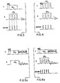
- FIG. 3 illustrates a portion of a pulse sequence of the invention.
- FIG. 4 is a portion of another pulse sequence of the invention.
- FIG. 5A is a CPMAS pulse sequence of prior art.
- FIG. 5B is the set of spectra resulting from the reference of FIG. 5A for several values of C 13 power.
- FIG. 6A is a CPMAS pulse sequence of the present invention.
- FIG. 6B shows spectra resulting from the FIG. 6A sequence for several values of C13 power.
- FIG. 7A illustrates the resonant signal amplitude as a function of excitation power for a static sample using the FIG. 5A sequence.
- FIG. 7B illustrates resonant signal amplitude as a function of excitation power for a rotating sample using the FIG. 5A sequence.
- FIG. 7C illustrates resonant signal amplitude as a function of excitation power using sequence of FIG. 6A.
- FIG. 1 Portions of an NMR apparatus embodying this invention are described schematically in FIG. 1.
- An acquisition control processor 10 communicates with first channel "I" rf transmitter 12 and second "S" rf transmitter 13 and with corresponding rf modulators 14 and 15. These separate rf transmitter channels in turn are directed to NMR probe 22 containing a sample for investigation.
- the probe 22 is situated within a magnetic field 21 ordinarily maintained within the bore 29 of superconducting magnet/cryostat 23.
- the probe assembly 22 for NMR studies also provides for the reception of the resonance signal excited in the sample by operation of rf channels "I" and/or "S".
- a signal originating from de-exciting nuclei is induced in a resonant circuit, (not shown), pre-amplified and directed to receiver 16, convened to a digital form and further processed by the acquisition processor and host computer (not shown).
- the probe 22 will include pneumatic apparatus for maintaining a gas bearing and gas actuated rotor to which the sample is secured. Means for effectuating such rotation and controlling same are well known in the art.
- the rotation rate of the rotor is observed with the spinning tachometer 32.
- a representative arrangement for providing such a signal is shown in FIG. 2 and utilizes a reflective spot 40 on the periphery of the rotor 38 which is illuminated by light source 42 and observed by a photo-diode 44 to provide a simple square wave signal 46 with a repetition rate representative of the rotation rate.
- the timing pulse combined in gate 48 with a Modulator Select signal actuates a gate whereby the desired modulation is impressed on the respective RF carrier.
- a first embodiment of the invention is further described in FIG. 3 in a general sense.
- Rotor pulses are developed as above described and are applied to gate "T” modulator 14 for manipulation of the magnetization of a first nuclear species (such as H 1 ) by a desired angle with respect to the magnetic field 21.
- a long cross polarization pulse (“CP") is applied to spin lock the "T” magnetization and cause precession of same about y (in the rotating frame of I).
- CP long cross polarization pulse
- S modulator 15 provides rf radiation for bringing a second nuclear species, such as C 13 to resonance.
- the proton modulator (14) provides for essentially continuous radiation while the C 13 modulator is synchronized through the aforesaid gating logic to correlate C 13 channel radiation with the rotor. While FIG. 3 indicates a repetition rate for the C 13 modulator equal to the rotor rate and in phase therewith, one will understand that these are not requirements of the invention.
- the occurence of rotor gated C 13 radiation may lead or lag the rotor pulse with any desired (substantially constant) phase. Further, the repetition rate may be any desired harmonic or sub-harmonic of the rotor rate.
- the duty cycle of the C 13 radiation may be any selected fraction of the rotor period. In the limit of 100% duty cycle, the advantage of rotor synchronization is lost. As the duty cycle approaches zero, the phenomenon of cross polarization is not achieved. The particular choice of duty cycle depends upon criteria outside the scope of this work.
- FIG. 4 a second embodiment is illustrated wherein both channels of rf irradiation are rotor synchronized. Again, the channel pulse repetition rate, phasing with respect to the rotor rate and the duty cycle are independently selectable for each channel.
- FIG. 5A a simple CPMAS sequence is shown in FIG. 5A wherein the C 13 FID is observed while decoupling radiations are applied to the protons. This sequence was applied to a sample of hexamethylbenzene (without rotor synchronization) spinning in about 6 KHZ.
- FIG. 5B the experimental spectra are repeated for 8 values of power applied to the C 13 resonance channel while the rf power applied to the proton channel was maintained constant.
- the data of FIG. 6B is obtained in the same manner as the data of FIG. 5B using the pulse sequence illustrated in FIG. 6A.
- This pulse sequence differs from the sequence of FIG. 5A in that the C 13 spins are repeatedly nutated in synchronous relation to the rotor pulse (s).
- the additional constraint of rotor synchronization following the present invention is applied with a repetition rate equal to the rotation rate with a duty cycle of 28%. It is evident that the signal-to-noise dependence of FIG. 5 has been greatly reduced and the relative intensities of multiplet members in the resulting spectra are substantially independent of variation in the C 13 power.
- FIGS. 7A and 7B The explanation for the improved performance for rotor synchronous cross polarization is aided by reference to FIGS. 7A and 7B.
- FIG. 7A the resonant signal amplitude is shematically indicated for a non-spinning sample as a function of the resonant frequency for one nuclear species in a cross polarization experiment.
- FIG. 7B indicates a corresponding behavior, given a spinning ⁇ R for the sample.
- FIG. 7B may be regarded as the effect of applying the rotor synchronous constraint to the excitation of C 13 in FIG. 6A is equivalent to a transformation into a reference frame rotating at the sample spinning rate ⁇ R , e.g.
- FIG. 7C where the signal amplitude response function exhibits the same shape with scale reduced is a function of duty cycle.
- FIG. 7C where the signal amplitude response function exhibits the same shape with scale reduced is a function of duty cycle.
- FIG. 7C the signal amplitude response function exhibits the same shape with scale reduced is a function of duty cycle.
- FIG. 6A corresponds to acquiring the data at some point along a curve such as that sketched in FIG. 7C.
- the resonant signal intensity for a spinning sample for which data is acquired without synchronization corresponds to acquiring data at corresponding points on the curve of FIG. 7B.
- Both of these figures may be regarded as describing a modulus of the resonant signal. Accordingly, the left most spectrum of FIG.
Landscapes
- Physics & Mathematics (AREA)
- Condensed Matter Physics & Semiconductors (AREA)
- General Physics & Mathematics (AREA)
- Spectroscopy & Molecular Physics (AREA)
- High Energy & Nuclear Physics (AREA)
- Investigating, Analyzing Materials By Fluorescence Or Luminescence (AREA)
- Magnetic Resonance Imaging Apparatus (AREA)
- Measuring Magnetic Variables (AREA)
- Spinning Or Twisting Of Yarns (AREA)
Description
- The present invention relates to nuclear magnetic resonance phenomena and in particular to the enhancement of such studies in the context of cross polarization measurements.
- Cross polarization experiments in NMR provide a vehicle for enhancing the resonance signal for nuclei which exhibit a low value of the gyromagnetic ratio γS through transfer of magnetization from a resonant nuclei exhibiting a high gyromagnetic ratio γI in relation to the nuclei of γS. This transfer occurs when the separate rotating frame precession frequencies for the two nuclear species are caused to coincide yielding the Hartman-Hahn condition.

- Where the subscripts and superscripts label respective nuclei of low (S) and high (I) gyromagnetic ratio such as C13 and protons, and the corresponding rf magnetic fields.
- For high resolution NMR it is most often desirable to mechanically rotate the sample about a selected axis. This mechanical rotation is ordinarily accomplished with a pneumatic apparatus for the purpose of averaging inhomogeneities of the field and, for solids, inhomogeneities of the sample structure. Rotation rates of the order of 103 - 104 Hertz are typical. One result of a mechanical rotation is the imposition of spinning side-bands on the NMR excitation and the NMR signal with the result that stringent conditions are imposed on the rf magnetic field amplitudes observed at the sample in a cross polarization experiment.
- In one technique of prior art the modulation arising from the spinning operation is removed by arranging for the spinner to be stationary during a cross polarization evolution period, t1. At the conclusion of the interval t1, the transverse magnetization is protected by application of an appropriately phased 90° pulse to preserve the magnetic properties of the system for a brief period while the spinner is brought up to speed, after which the experiment is completed with the rf fields applied to the respective spin subsystems. In this approach the measurement requires great expenditure of time to allow for the rotor to return to a stable rotation at the desired rate. During this return to the stable rotation condition some loss of magnetization will be experienced (as a function T1) thereby degrading the signal to noise ratio. An example of this prior art approach will be found in J. Mag. Res., Vol. 79, pp. 299-306 (1988).
- It is also known to synchronize rf pulses with the sample rotor at multiple angular intervals of sample rotation following a period of cross polarization for the purpose of adapting the width of a so-called powder pattern (continuous spectrum arising from random oriented crystallites) to a desired frequency interval so as to avoid overlap of powder patterns. The technique is discussed by Yarin-Agaev et al., J. Mag. Res., G. 47, pp. 51-60 (1982).
US-A-4,628,263 discloses a sample with a single resonant species. The present invention provides an improvement over such an arrangement by the features of the characterising clause ofclaim 1. - In the present invention the efficiency of polarization transfer and certain other benefits are found to result from the use of rotor synchronized pulses employed to establish the Hartman-Hahn condition in an improved manner. An important example of auxiliary benefit is that with the present invention the integrated resonant signal acquires greater independence of rotor speed and Hartman-Hahn efficiency, thereby providing a more reliable quantitative indicia of the density of specific nuclei. This consequence permits spinning at high rates, a desirable goal at the high magnetic fields characterizing the subject measurements. Further, the practice of this invention increases tolerance of mechanical instability which may accompany the highest spinning rates. Thus, there is not required the complexity of maintaining an exacting spin rate stabilization servo-loop.
- The present invention is directed to removal or reduction of the spinning modulation imposed on a cross polarization condition due to sample spinning. It is accomplished by applying a rotor synchronous modulation to either, or both rf fields employed to produce the cross polarization condition.
- The rotor-synchronous modulation may be directed to the rf amplitude or the phase. This modulation may be derived from the rotor by any of a number of well known arrangements.
- In the accompanying drawings,
- FIG. 1 is a schematic Illustration of apparatus of the invention.
- FIG. 2 is a typical arrangement for obtaining rotor synchronisation.
- FIG. 3 illustrates a portion of a pulse sequence of the invention.
- FIG. 4 is a portion of another pulse sequence of the invention.
- FIG. 5A is a CPMAS pulse sequence of prior art.
- FIG. 5B is the set of spectra resulting from the reference of FIG. 5A for several values of C13 power.
- FIG. 6A is a CPMAS pulse sequence of the present invention.
- FIG. 6B shows spectra resulting from the FIG. 6A sequence for several values of C13 power.
- FIG. 7A illustrates the resonant signal amplitude as a function of excitation power for a static sample using the FIG. 5A sequence.
- FIG. 7B illustrates resonant signal amplitude as a function of excitation power for a rotating sample using the FIG. 5A sequence.
- FIG. 7C illustrates resonant signal amplitude as a function of excitation power using sequence of FIG. 6A.
- Portions of an NMR apparatus embodying this invention are described schematically in FIG. 1. An acquisition control processor 10 communicates with first channel "I"
rf transmitter 12 and second "S"rf transmitter 13 and withcorresponding rf modulators 14 and 15. These separate rf transmitter channels in turn are directed toNMR probe 22 containing a sample for investigation. Theprobe 22 is situated within amagnetic field 21 ordinarily maintained within thebore 29 of superconducting magnet/cryostat 23. - The
probe assembly 22 for NMR studies also provides for the reception of the resonance signal excited in the sample by operation of rf channels "I" and/or "S". A signal originating from de-exciting nuclei is induced in a resonant circuit, (not shown), pre-amplified and directed toreceiver 16, convened to a digital form and further processed by the acquisition processor and host computer (not shown). - It is common practice in high resolution NMR studies to cause the sample to undergo a mechanical rotation about a selected axis. Thus the
probe 22 will include pneumatic apparatus for maintaining a gas bearing and gas actuated rotor to which the sample is secured. Means for effectuating such rotation and controlling same are well known in the art. The rotation rate of the rotor is observed with thespinning tachometer 32. A representative arrangement for providing such a signal is shown in FIG. 2 and utilizes areflective spot 40 on the periphery of therotor 38 which is illuminated by light source 42 and observed by a photo-diode 44 to provide a simplesquare wave signal 46 with a repetition rate representative of the rotation rate. The timing pulse combined ingate 48 with a Modulator Select signal actuates a gate whereby the desired modulation is impressed on the respective RF carrier. - A first embodiment of the invention is further described in FIG. 3 in a general sense. Rotor pulses are developed as above described and are applied to gate "T" modulator 14 for manipulation of the magnetization of a first nuclear species (such as H1) by a desired angle with respect to the
magnetic field 21. Immediately thereafter, a long cross polarization pulse ("CP") is applied to spin lock the "T" magnetization and cause precession of same about y (in the rotating frame of I). A similar spin-lock and precession about y in the rotating frame of S permits enhancement of the latter signal (theoretically) by amount γI/γS. "S"modulator 15 provides rf radiation for bringing a second nuclear species, such as C13 to resonance. The proton modulator (14) provides for essentially continuous radiation while the C13 modulator is synchronized through the aforesaid gating logic to correlate C13 channel radiation with the rotor. While FIG. 3 indicates a repetition rate for the C13 modulator equal to the rotor rate and in phase therewith, one will understand that these are not requirements of the invention. The occurence of rotor gated C13 radiation may lead or lag the rotor pulse with any desired (substantially constant) phase. Further, the repetition rate may be any desired harmonic or sub-harmonic of the rotor rate. The duty cycle of the C13 radiation may be any selected fraction of the rotor period. In the limit of 100% duty cycle, the advantage of rotor synchronization is lost. As the duty cycle approaches zero, the phenomenon of cross polarization is not achieved. The particular choice of duty cycle depends upon criteria outside the scope of this work. - The pulse sequences of FIGs. 3 and 4 are not complete. Rather these represent improvement in the cross polarization or contact portion of any experiment wherein cross polarization is employed with a spinning sample. Accordingly, the selection of such further operation as decoupling, further rotations of either spin species, timing of evaluation intervals or data acquisition are outside the scope of this work.
- In FIG. 4 a second embodiment is illustrated wherein both channels of rf irradiation are rotor synchronized. Again, the channel pulse repetition rate, phasing with respect to the rotor rate and the duty cycle are independently selectable for each channel.
- The portion of the measurement procedure following the rotor synchronized Hartman-Hahn condition is unspecified and thus beyond the scope of the present invention. For the sake of illustration of the advantage of the invention, a simple CPMAS sequence is shown in FIG. 5A wherein the C13 FID is observed while decoupling radiations are applied to the protons. This sequence was applied to a sample of hexamethylbenzene (without rotor synchronization) spinning in about 6 KHZ. At FIG. 5B the experimental spectra are repeated for 8 values of power applied to the C13 resonance channel while the rf power applied to the proton channel was maintained constant. One observes that at the lowest C13 power no spectrum is obtained and further that there is a decided dependence for signal-to-noise which is observed over the range of C13 power. Moreover, the relative intensities of the multiplet members within any one spectrum depend upon the power applied at the C13 channel.
- The data of FIG. 6B is obtained in the same manner as the data of FIG. 5B using the pulse sequence illustrated in FIG. 6A. This pulse sequence differs from the sequence of FIG. 5A in that the C13 spins are repeatedly nutated in synchronous relation to the rotor pulse (s). The additional constraint of rotor synchronization following the present invention is applied with a repetition rate equal to the rotation rate with a duty cycle of 28%. It is evident that the signal-to-noise dependence of FIG. 5 has been greatly reduced and the relative intensities of multiplet members in the resulting spectra are substantially independent of variation in the C13 power.
- The explanation for the improved performance for rotor synchronous cross polarization is aided by reference to FIGS. 7A and 7B. In FIG. 7A, the resonant signal amplitude is shematically indicated for a non-spinning sample as a function of the resonant frequency for one nuclear species in a cross polarization experiment. For a spinning sample, FIG. 7B indicates a corresponding behavior, given a spinning ωR for the sample. FIG. 7B may be regarded as the effect of applying the rotor synchronous constraint to the excitation of C13 in FIG. 6A is equivalent to a transformation into a reference frame rotating at the sample spinning rate ωR, e.g. the stationary condition obtains because the effect of the mechanical rotation at rate ωR has been removed by the synchronous constraint. This behavior is illustrated in FIG. 7C, where the signal amplitude response function exhibits the same shape with scale reduced is a function of duty cycle. Each of the several spectra of FIG. 6A corresponds to acquiring the data at some point along a curve such as that sketched in FIG. 7C. In contrast, the resonant signal intensity for a spinning sample for which data is acquired without synchronization corresponds to acquiring data at corresponding points on the curve of FIG. 7B. Both of these figures may be regarded as describing a modulus of the resonant signal. Accordingly, the left most spectrum of FIG. 6A is nicely observed, whereas the corresponding spectrum for the nonsynchronous case is absent. That value of the C13 excitation power is assumed to correspond, at least approximately, to a deep local minimum of the sketch of FIG. 7B. Most of the spectrum of FIG. 6A are distributed over the relatively flat region of the FIG. 7C sketch whereas the corresponding condition for FIG. 7B are subject to an oscillatory factor superimposed on the smooth behavior of FIG. 7C.
Claims (5)
- Magnetic resonance apparatus for the study of the composition of a sample comprising distinct first (I) and second (S) nuclear spins, the apparatus comprisingmeans for imposing a polarising static magnetic field (21) on said sample,first (12) and second (13) radio frequency (RF) irradiation means for imposing first and second time-dependent oscillatory RF magnetic fields on said sample in a direction orthogonal to said static magnetic field whereby said nuclear spins are excited to resonance, said first and second RF irradiation means being adapted to supply RF magnetic fields of amplitudes to satisfy the equality of the products of each said RF magnetic field with the gyromagnetic ratio of the corresponding nuclear spin,receiver means (16) for obtaining an RF signal from the de-excitation of said nuclear spins,sample rotation means (38) for spinning the sample about a selected axis, said sample rotation means comprising synchronous signal generating means (40, 42, 44) to provide indicia of the instantaneous angular displacement of the spinning sample,and RF modulation means (14, 15) for modulating at least one of said first and second RF irradiations synchronously to said synchronous signal generating means,characterised in that,
in order at least to reduce the spinning modulation imposed on a cross-polarisation condition due to sample spinning, the apparatus comprises control means suitably programmed for causing said RF modulation means to apply, during a cross polarization period of an NMR pulse sequence, a modulation synchronised to the sample rotation to at least one of said RF magnetic fields employed to produce the cross polarization condition for the first and second nuclear spins. - Apparatus as claimed in claim 1 wherein said rotor synchronous modulation is a phase modulation of at least one said RF irradiation means.
- Apparatus as claimed in claim 1 wherein said rotor synchronous modulation is an amplitude modulation of at least one said RF irradiation means.
- Apparatus as claimed in claim 2 or claim 3 wherein said apparatus comprises first and second modulation means for applying, during said cross polarization period, a modulation synchronised to the sample rotation to both said first and second RF magnetic fields.
- A method of measuring a nuclear magnetic resonance (NMR) signal obtained from a rotating sample comprising distinct first (I) and second (S) resonating nuclear spins exhibiting respective first and second gyromagnetic ratios, the method comprisingimposing a polarising static magnetic field (21) on said sample,imposing first and second time-dependent oscillatory radio frequency (RF) magnetic fields on said sample in a direction orthogonal to said static magnetic field whereby said nuclear spins are excited to resonance,supplying to said sample, during a cross-polarisation period of the NMR measuring sequence, RF magnetic fields of amplitudes to satisfy the equality of the products of each said RF magnetic field with the gyromagnetic ratio of the corresponding nuclear spin,deriving a rotation signal from said rotating sample to provide indicia of the instantaneous angular displacement of the spinning sample, andreceiving an RF signal from the de-excitation of said nuclear spins,characterised in that,
in order at least to reduce the spinning modulation imposed on the cross-polarisation condition due to sample spinning, the method comprises the step of applying, during said cross-polarisation period, a modulation in synchronous relationship with said rotation signal to at least one of said RF magnetic fields employed to produce the cross-polarisation condition for the first and second nuclear spins.
Applications Claiming Priority (2)
| Application Number | Priority Date | Filing Date | Title |
|---|---|---|---|
| US07/555,955 US5170120A (en) | 1990-07-19 | 1990-07-19 | Rotor synchronized cross polarization of solid state nmr |
| US555955 | 1990-07-19 |
Publications (2)
| Publication Number | Publication Date |
|---|---|
| EP0467704A1 EP0467704A1 (en) | 1992-01-22 |
| EP0467704B1 true EP0467704B1 (en) | 1996-08-28 |
Family
ID=24219290
Family Applications (1)
| Application Number | Title | Priority Date | Filing Date |
|---|---|---|---|
| EP91306605A Expired - Lifetime EP0467704B1 (en) | 1990-07-19 | 1991-07-19 | Rotor synchronized cross polarization of solid state NMR |
Country Status (4)
| Country | Link |
|---|---|
| US (1) | US5170120A (en) |
| EP (1) | EP0467704B1 (en) |
| JP (1) | JP3167146B2 (en) |
| DE (1) | DE69121652T2 (en) |
Families Citing this family (12)
| Publication number | Priority date | Publication date | Assignee | Title |
|---|---|---|---|---|
| DE69208277T2 (en) * | 1991-04-05 | 1996-10-24 | Bruker Instr Inc | Method for the preparation of CPMAS NMR spectra |
| US5245284A (en) * | 1991-04-05 | 1993-09-14 | Bruker Instruments, Inc. | Method for editing CPMAS solid-state NMR spectra |
| DE69227496T2 (en) * | 1991-09-14 | 1999-07-15 | Bruker Analytik Gmbh, 76287 Rheinstetten | Localized solid-state spectroscopy using magnetic nuclear magnetic resonance with disk-selective polarization transmission |
| US5886525A (en) * | 1997-03-17 | 1999-03-23 | The United States Of America As Represented By The Secretary Of The Navy | Apparatus and method for performing NMR spectroscopy on solid sample by rotation |
| JP2003177172A (en) * | 2001-10-03 | 2003-06-27 | Jeol Ltd | High-speed spinner for solid-state NMR measurement |
| US7196521B2 (en) * | 2005-03-29 | 2007-03-27 | Doty Scientific, Inc. | NMR MAS electret spin rate detection |
| US8849372B2 (en) * | 2006-11-22 | 2014-09-30 | The General Hospital Corporation | Method for magnetic resonance imaging using stimulus induced rotary saturation with a contrast agent |
| US7535224B2 (en) * | 2007-05-29 | 2009-05-19 | Jian Zhi Hu | Discrete magic angle turning system, apparatus, and process for in situ magnetic resonance spectroscopy and imaging |
| US7956613B2 (en) * | 2008-05-02 | 2011-06-07 | The General Hospital Corporation | Method for imaging acoustically induced rotary saturation with a magnetic resonance imaging system |
| US8970217B1 (en) | 2010-04-14 | 2015-03-03 | Hypres, Inc. | System and method for noise reduction in magnetic resonance imaging |
| US9211082B2 (en) | 2011-06-30 | 2015-12-15 | The General Hospital Corporation | Method for magnetic resonance imaging using saturation harmonic induced rotary saturation |
| CN103616593B (en) * | 2013-11-28 | 2015-12-02 | 国家电网公司 | Can capacity calculation methods after a kind of multiple unimodule SiC de-excitation resistance parallel connection |
Family Cites Families (4)
| Publication number | Priority date | Publication date | Assignee | Title |
|---|---|---|---|---|
| US4305036A (en) * | 1979-07-09 | 1981-12-08 | Gesellschaft Fur Biotechnologische Forschung Mbh | Method and apparatus for high resolution nuclear magnetic resonance spectroscopy |
| US4301410A (en) * | 1979-09-28 | 1981-11-17 | International Business Machines Corporation | Spin imaging in solids using synchronously rotating field gradients and samples |
| US4628263A (en) * | 1983-06-13 | 1986-12-09 | Jeol Ltd. | Nuclear magnetic resonance spectrometer |
| US4996483A (en) * | 1989-09-12 | 1991-02-26 | The United States Of America As Represented By The United States Department Of Energy | Spinning angle optical calibration apparatus |
-
1990
- 1990-07-19 US US07/555,955 patent/US5170120A/en not_active Expired - Lifetime
-
1991
- 1991-07-19 JP JP20331091A patent/JP3167146B2/en not_active Expired - Fee Related
- 1991-07-19 EP EP91306605A patent/EP0467704B1/en not_active Expired - Lifetime
- 1991-07-19 DE DE69121652T patent/DE69121652T2/en not_active Expired - Lifetime
Also Published As
| Publication number | Publication date |
|---|---|
| US5170120A (en) | 1992-12-08 |
| DE69121652T2 (en) | 1997-01-23 |
| EP0467704A1 (en) | 1992-01-22 |
| JPH04232882A (en) | 1992-08-21 |
| JP3167146B2 (en) | 2001-05-21 |
| DE69121652D1 (en) | 1996-10-02 |
Similar Documents
| Publication | Publication Date | Title |
|---|---|---|
| KR880001531B1 (en) | NMR Imaging Apparatus and Method | |
| US4318043A (en) | Method and apparatus for rapid NMR imaging of nuclear densities within an object | |
| US5168226A (en) | Acquisition of multiple images in fast spin echo nmr scans | |
| KR880001529B1 (en) | Method for seletive nmr inaging of chemically-shifted nuclei | |
| US4628262A (en) | Multiple echo chemical shift imaging | |
| GB2026172A (en) | Method and apparatus for determining the relative densities of nuclei within an object using nuclear magnetic resonance | |
| US5170120A (en) | Rotor synchronized cross polarization of solid state nmr | |
| JPH0332756B2 (en) | ||
| EP0209374A2 (en) | NMR phase encoding using phase-varying rf pulses | |
| US4531094A (en) | Methods and apparatus of obtaining NMR spectra | |
| US5798643A (en) | Method for operating an NMR tomography apparatus suitable for use with a chronologically constant basic magnetic field inhomogeneity | |
| US5099207A (en) | Method of determining a nuclear magnetization distribution of a sub-volume of an object, method of shimming a part of a steady field in which the object is situated, and magnetic resonance device for performing such a method | |
| US4684893A (en) | Field gradient correction apparatus for compensating static field inhomogeneities in NMR imaging system | |
| Hennig | Chemical shift imaging with phase‐encoding RF pulses | |
| JP2633259B2 (en) | Solid-state mapping by nuclear magnetic resonance technology. | |
| US4777439A (en) | Spatially localized spectroscopy | |
| US4707659A (en) | Method and device for determining an NMR distribution in a region of a body | |
| US4672318A (en) | Method of measuring the static magnetic field distribution in an NMR inspection system | |
| EP0541636B1 (en) | Improvements in, or relating to magnetic resonance spectroscopy and imaging | |
| JPH02274225A (en) | Distribution-determining method for nuclear magnetization | |
| EP0153303B1 (en) | Method and apparatus for obtaining n.m.r. spectra | |
| EP0207765B1 (en) | Magnetic resonance imaging apparatus and method utilizing a composite rf pulse | |
| US5189370A (en) | Chemical shift imaging | |
| US4672319A (en) | Multiple pulse excitation in NMR imaging | |
| US5317261A (en) | Volume-selective magnetic resonance imaging method and device |
Legal Events
| Date | Code | Title | Description |
|---|---|---|---|
| PUAI | Public reference made under article 153(3) epc to a published international application that has entered the european phase |
Free format text: ORIGINAL CODE: 0009012 |
|
| AK | Designated contracting states |
Kind code of ref document: A1 Designated state(s): CH DE FR GB LI |
|
| 17P | Request for examination filed |
Effective date: 19920123 |
|
| 17Q | First examination report despatched |
Effective date: 19940321 |
|
| GRAH | Despatch of communication of intention to grant a patent |
Free format text: ORIGINAL CODE: EPIDOS IGRA |
|
| GRAH | Despatch of communication of intention to grant a patent |
Free format text: ORIGINAL CODE: EPIDOS IGRA |
|
| GRAA | (expected) grant |
Free format text: ORIGINAL CODE: 0009210 |
|
| AK | Designated contracting states |
Kind code of ref document: B1 Designated state(s): CH DE FR GB LI |
|
| REG | Reference to a national code |
Ref country code: CH Ref legal event code: NV Representative=s name: BOVARD AG PATENTANWAELTE |
|
| REF | Corresponds to: |
Ref document number: 69121652 Country of ref document: DE Date of ref document: 19961002 |
|
| ET | Fr: translation filed | ||
| PLBE | No opposition filed within time limit |
Free format text: ORIGINAL CODE: 0009261 |
|
| STAA | Information on the status of an ep patent application or granted ep patent |
Free format text: STATUS: NO OPPOSITION FILED WITHIN TIME LIMIT |
|
| 26N | No opposition filed | ||
| REG | Reference to a national code |
Ref country code: GB Ref legal event code: 746 Effective date: 19980921 |
|
| REG | Reference to a national code |
Ref country code: FR Ref legal event code: D6 |
|
| PGFP | Annual fee paid to national office [announced via postgrant information from national office to epo] |
Ref country code: CH Payment date: 19990705 Year of fee payment: 9 |
|
| PG25 | Lapsed in a contracting state [announced via postgrant information from national office to epo] |
Ref country code: LI Free format text: LAPSE BECAUSE OF NON-PAYMENT OF DUE FEES Effective date: 20000731 Ref country code: CH Free format text: LAPSE BECAUSE OF NON-PAYMENT OF DUE FEES Effective date: 20000731 |
|
| REG | Reference to a national code |
Ref country code: FR Ref legal event code: TP |
|
| REG | Reference to a national code |
Ref country code: CH Ref legal event code: PL |
|
| REG | Reference to a national code |
Ref country code: GB Ref legal event code: 732E |
|
| REG | Reference to a national code |
Ref country code: GB Ref legal event code: IF02 |
|
| PGFP | Annual fee paid to national office [announced via postgrant information from national office to epo] |
Ref country code: FR Payment date: 20100805 Year of fee payment: 20 Ref country code: DE Payment date: 20100728 Year of fee payment: 20 |
|
| PGFP | Annual fee paid to national office [announced via postgrant information from national office to epo] |
Ref country code: GB Payment date: 20100726 Year of fee payment: 20 |
|
| REG | Reference to a national code |
Ref country code: GB Ref legal event code: 732E Free format text: REGISTERED BETWEEN 20110324 AND 20110330 |
|
| REG | Reference to a national code |
Ref country code: DE Ref legal event code: R071 Ref document number: 69121652 Country of ref document: DE |
|
| REG | Reference to a national code |
Ref country code: DE Ref legal event code: R071 Ref document number: 69121652 Country of ref document: DE |
|
| REG | Reference to a national code |
Ref country code: GB Ref legal event code: PE20 Expiry date: 20110718 |
|
| REG | Reference to a national code |
Ref country code: FR Ref legal event code: TP Owner name: AGILENT TECHNOLOGIES INC, US Effective date: 20110823 |
|
| PG25 | Lapsed in a contracting state [announced via postgrant information from national office to epo] |
Ref country code: GB Free format text: LAPSE BECAUSE OF EXPIRATION OF PROTECTION Effective date: 20110718 |
|
| REG | Reference to a national code |
Ref country code: DE Ref legal event code: R082 Ref document number: 69121652 Country of ref document: DE Representative=s name: EISENFUEHR, SPEISER & PARTNER, DE |
|
| REG | Reference to a national code |
Ref country code: DE Ref legal event code: R082 Ref document number: 69121652 Country of ref document: DE Representative=s name: EISENFUEHR, SPEISER & PARTNER, DE Effective date: 20111130 Ref country code: DE Ref legal event code: R081 Ref document number: 69121652 Country of ref document: DE Owner name: AGILENT TECHNOLOGIES INC., US Free format text: FORMER OWNER: VARIAN, INC., PALO ALTO, US Effective date: 20111130 Ref country code: DE Ref legal event code: R081 Ref document number: 69121652 Country of ref document: DE Owner name: AGILENT TECHNOLOGIES INC., SANTA CLARA, US Free format text: FORMER OWNER: VARIAN, INC., PALO ALTO, CALIF., US Effective date: 20111130 Ref country code: DE Ref legal event code: R082 Ref document number: 69121652 Country of ref document: DE Representative=s name: EISENFUEHR SPEISER PATENTANWAELTE RECHTSANWAEL, DE Effective date: 20111130 |
|
| PG25 | Lapsed in a contracting state [announced via postgrant information from national office to epo] |
Ref country code: DE Free format text: LAPSE BECAUSE OF EXPIRATION OF PROTECTION Effective date: 20110720 |