EP0467313B1 - Method and system for spreading a tow of fibers - Google Patents
Method and system for spreading a tow of fibers Download PDFInfo
- Publication number
- EP0467313B1 EP0467313B1 EP91111884A EP91111884A EP0467313B1 EP 0467313 B1 EP0467313 B1 EP 0467313B1 EP 91111884 A EP91111884 A EP 91111884A EP 91111884 A EP91111884 A EP 91111884A EP 0467313 B1 EP0467313 B1 EP 0467313B1
- Authority
- EP
- European Patent Office
- Prior art keywords
- tow
- fibres
- fibers
- spreader
- spreading
- Prior art date
- Legal status (The legal status is an assumption and is not a legal conclusion. Google has not performed a legal analysis and makes no representation as to the accuracy of the status listed.)
- Expired - Lifetime
Links
Images

Classifications
-
- D—TEXTILES; PAPER
- D01—NATURAL OR MAN-MADE THREADS OR FIBRES; SPINNING
- D01G—PRELIMINARY TREATMENT OF FIBRES, e.g. FOR SPINNING
- D01G1/00—Severing continuous filaments or long fibres, e.g. stapling
-
- D—TEXTILES; PAPER
- D02—YARNS; MECHANICAL FINISHING OF YARNS OR ROPES; WARPING OR BEAMING
- D02J—FINISHING OR DRESSING OF FILAMENTS, YARNS, THREADS, CORDS, ROPES OR THE LIKE
- D02J1/00—Modifying the structure or properties resulting from a particular structure; Modifying, retaining, or restoring the physical form or cross-sectional shape, e.g. by use of dies or squeeze rollers
- D02J1/18—Separating or spreading
-
- B—PERFORMING OPERATIONS; TRANSPORTING
- B05—SPRAYING OR ATOMISING IN GENERAL; APPLYING FLUENT MATERIALS TO SURFACES, IN GENERAL
- B05C—APPARATUS FOR APPLYING FLUENT MATERIALS TO SURFACES, IN GENERAL
- B05C19/00—Apparatus specially adapted for applying particulate materials to surfaces
- B05C19/02—Apparatus specially adapted for applying particulate materials to surfaces using fluidised-bed techniques
-
- B—PERFORMING OPERATIONS; TRANSPORTING
- B05—SPRAYING OR ATOMISING IN GENERAL; APPLYING FLUENT MATERIALS TO SURFACES, IN GENERAL
- B05C—APPARATUS FOR APPLYING FLUENT MATERIALS TO SURFACES, IN GENERAL
- B05C9/00—Apparatus or plant for applying liquid or other fluent material to surfaces by means not covered by any preceding group, or in which the means of applying the liquid or other fluent material is not important
- B05C9/08—Apparatus or plant for applying liquid or other fluent material to surfaces by means not covered by any preceding group, or in which the means of applying the liquid or other fluent material is not important for applying liquid or other fluent material and performing an auxiliary operation
- B05C9/14—Apparatus or plant for applying liquid or other fluent material to surfaces by means not covered by any preceding group, or in which the means of applying the liquid or other fluent material is not important for applying liquid or other fluent material and performing an auxiliary operation the auxiliary operation involving heating or cooling
-
- B—PERFORMING OPERATIONS; TRANSPORTING
- B65—CONVEYING; PACKING; STORING; HANDLING THIN OR FILAMENTARY MATERIAL
- B65H—HANDLING THIN OR FILAMENTARY MATERIAL, e.g. SHEETS, WEBS, CABLES
- B65H51/00—Forwarding filamentary material
- B65H51/005—Separating a bundle of forwarding filamentary materials into a plurality of groups
-
- D—TEXTILES; PAPER
- D06—TREATMENT OF TEXTILES OR THE LIKE; LAUNDERING; FLEXIBLE MATERIALS NOT OTHERWISE PROVIDED FOR
- D06B—TREATING TEXTILE MATERIALS USING LIQUIDS, GASES OR VAPOURS
- D06B13/00—Treatment of textile materials with liquids, gases or vapours with aid of vibration
-
- D—TEXTILES; PAPER
- D06—TREATMENT OF TEXTILES OR THE LIKE; LAUNDERING; FLEXIBLE MATERIALS NOT OTHERWISE PROVIDED FOR
- D06M—TREATMENT, NOT PROVIDED FOR ELSEWHERE IN CLASS D06, OF FIBRES, THREADS, YARNS, FABRICS, FEATHERS OR FIBROUS GOODS MADE FROM SUCH MATERIALS
- D06M10/00—Physical treatment of fibres, threads, yarns, fabrics or fibrous goods made from such materials, e.g. by ultrasonic waves, corona discharge, irradiation, electric currents or magnetic fields; Physical treatment combined with treatment with chemical compounds or elements
- D06M10/003—Treatment with radio-waves or microwaves
-
- D—TEXTILES; PAPER
- D06—TREATMENT OF TEXTILES OR THE LIKE; LAUNDERING; FLEXIBLE MATERIALS NOT OTHERWISE PROVIDED FOR
- D06M—TREATMENT, NOT PROVIDED FOR ELSEWHERE IN CLASS D06, OF FIBRES, THREADS, YARNS, FABRICS, FEATHERS OR FIBROUS GOODS MADE FROM SUCH MATERIALS
- D06M23/00—Treatment of fibres, threads, yarns, fabrics or fibrous goods made from such materials, characterised by the process
- D06M23/06—Processes in which the treating agent is dispersed in a gas, e.g. aerosols
-
- D—TEXTILES; PAPER
- D06—TREATMENT OF TEXTILES OR THE LIKE; LAUNDERING; FLEXIBLE MATERIALS NOT OTHERWISE PROVIDED FOR
- D06M—TREATMENT, NOT PROVIDED FOR ELSEWHERE IN CLASS D06, OF FIBRES, THREADS, YARNS, FABRICS, FEATHERS OR FIBROUS GOODS MADE FROM SUCH MATERIALS
- D06M23/00—Treatment of fibres, threads, yarns, fabrics or fibrous goods made from such materials, characterised by the process
- D06M23/08—Processes in which the treating agent is applied in powder or granular form
-
- B—PERFORMING OPERATIONS; TRANSPORTING
- B29—WORKING OF PLASTICS; WORKING OF SUBSTANCES IN A PLASTIC STATE IN GENERAL
- B29B—PREPARATION OR PRETREATMENT OF THE MATERIAL TO BE SHAPED; MAKING GRANULES OR PREFORMS; RECOVERY OF PLASTICS OR OTHER CONSTITUENTS OF WASTE MATERIAL CONTAINING PLASTICS
- B29B15/00—Pretreatment of the material to be shaped, not covered by groups B29B7/00 - B29B13/00
- B29B15/08—Pretreatment of the material to be shaped, not covered by groups B29B7/00 - B29B13/00 of reinforcements or fillers
- B29B15/10—Coating or impregnating independently of the moulding or shaping step
- B29B15/12—Coating or impregnating independently of the moulding or shaping step of reinforcements of indefinite length
-
- B—PERFORMING OPERATIONS; TRANSPORTING
- B65—CONVEYING; PACKING; STORING; HANDLING THIN OR FILAMENTARY MATERIAL
- B65H—HANDLING THIN OR FILAMENTARY MATERIAL, e.g. SHEETS, WEBS, CABLES
- B65H2701/00—Handled material; Storage means
- B65H2701/30—Handled filamentary material
- B65H2701/31—Textiles threads or artificial strands of filaments
Definitions
- the present invention relates to a method and system for spreading a tow of fibers using energy from a gas vibrating means adjacent to the fibers.
- U.S. Patent No. 3,704,485 to Hall describes a method and apparatus for spreading a tow of fibers using a speaker or other gas vibrating means adjacent to the fibers.
- the tow of fibers passes over the speaker under low tension, essentially by tension created by the weight of the fibers, and is spread by the sound waves in the gaseous medium, usually air, created by the speaker.
- the Hall method works well; however, the tow of fibers are unrestrained while being acted upon by the sound waves and can be easily damaged. Also, there is no means described by Hall for maintaining the spread of the fibers over the speaker so that the maximum spread is achieved. Also Hall uses internally wound spools for feeding the tow of fibers which provide little or no tension on the fibers of the tow.
- the present invention achieves its object by providing a system for spreading a tow of fibers comprising the features set out in claim 1.
- the present invention also claims a method for spreading a tow of fibers comprising the steps set out in claim 10.
- a system for spreading fibers in a tow of the fiber comprises: feed means for feeding the tow of the fibers; spreader means for spreading the tow of the fibers from the feed means including a vibrating means for a gaseous medium mounted in a housing adjacent to the tow of the fibers and multiple rod means mounted adjacent to the vibrating means and spaced apart in the direction of movement of the tow of the fibers such that the tow of the fibers zig-zag over and under the rod means so that the fibers in the tow spread apart as the tow moves between the rod means; and take-up means for the spread apart fibers in the tow after the tow has moved through the spreader means.
- a method for spreading fibers of a tow of fibers comprises: providing a system for spreading fibers in a tow of the fibers which comprises: feed means for feeding the tow of the fibers; spreader means for spreading the tow of the fibers from the feed means including a vibrating means for a gaseous medium mounted in a housing adjacent to the tow of the fibers to spread the fibers and multiple rod means mounted adjacent to the vibrating means and spaced apart in the direction of movement of the tow of the fibers such that the tow of the fibers zig-zag over and under the rod means so that the fibers in the tow spread apart as the tow moves between the rod means; and take-up means for the spread apart fibers in the tow after the tow has moved through the spreader means; feeding the tow of the fibers through the spreader and between the feed means and the take-up means to provide the spread apart fibers in the tow on the take-up means.
- the spreader system operates on the principle that a pulsating flow of energy in a gaseous medium spreads a collimated fiber tow into its individual filaments.
- the source of this energy is a vibrating cone or diaphragm of a speaker or other vibrating means which oscillates at a predetermined frequency and amplitude.
- An acoustic horn or vibrating diaphragm can also be used to produce the vibrations in the gaseous medium.
- the acoustic energy provided by the speaker enables the fiber tow to spread to any desired width. For a particular fiber tow, there is a narrow range of frequencies at which the efficiency of spreading is the maximum.
- the spreading width is a function of tow tension in the region over the spreader and the amplitude of the sound wave once the right frequency is selected.
- the spreading width increases with increasing amplitude (frequency and tension constant) to a plateau beyond which there is no appreciable increase.
- the spreading width increases with decreasing tension to a point beyond which there is too much slack which causes uncontrollable fiber motion and oscillations resulting in fiber damage.
- the acoustic speaker operates in air or in any suitable gas whether reactive (e.g. oxygen) or non-reactive (nitrogen) in an enclosed space around the speaker.
- reactive e.g. oxygen
- non-reactive nitrogen
- the acoustic speaker preferably has a rating of about 8 ohms and 100 watts and a sound level of about 80 to 130 dB.
- the frequency is between about 32 and 39 Hz.
- any frequency can be used, preferably in the audio to ultrasonic range. Usually the range is between about 1 and 20,000 Hz.
- the fibers can be of any diameter. Preferably fibers have a diameter of between about 1 and 250 microns.
- the tow preferably contains between about 30 and 250,000 individual fibers.
- the fibers can be plastic, ceramic or metallic.
- the rods have a curved surface over which the spreading fibers pass.
- the rods preferably are circular in cross-section.
- the rods can be fixed in position; however, it is preferred that they rotate when they are circular in cross-section to avoid damage to the fibers.
- the fibers are passed in low tension over the speaker. This is most easily accomplished by providing nip rollers or other restraining means on either side of the spreader or controlled tension between the take-up spool and the feed spool.
- the spread fibers can be impregnated with a resin.
- the method according to US-A-5,102,690, is preferred.
- Figure 1 is a front schematic view of the system of the present invention particularly illustrating the zig-zag of the spreading tow of fibers over rods 16d wound above the diaphragm of a speaker 16a.
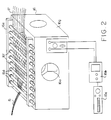
- Figure 2 is a front perspective view of the cabinet and speaker 16a showing the rods 16d mounted on a holder 16e.
- FIG. 1 A schematic of the preferred spreading system is shown in Figure 1.
- the fiber tow 12 of narrow width is unwound from the spool 11 by a pair of nip rollers 14 through a guide 13. Both externally and internally (not shown) wound spools can be used in this invention.
- the fiber tow 12 is held at a constant level of tension between the nip rollers 14 and a second pair of nip rollers 18 mounted between the first pair of rollers 14 and the takeup drum 19. This arrangement ensures that the tow between 15 and 17 is held at the desired level of tension over the spreader 16 regardless of the level of tension of the tow 12 in the fiber spool 11.
- the speed of the take-up drum 19 can be regulated to maintain a constant level of tension in the fiber tow as it passes over the spreader 16.
- the spreader 16 which consists of a speaker 16a powered by a frequency generator 16c and a power amplifier 16b spreads the incoming fiber tow into its individual filaments 17. The spreading tow zig-zags over and under a series of highly polished shafts or rods 16d. The spread tow at 17 then passes through the second pair of nip rollers 8 and is wound on the take-up drum 19.
- Guide 20 can be used to maintain the spread of the fibers at 17; however, it is not necessary.
- Spreader 16 is shown in more detail in Figure 2. It consists of a speaker 16a mounted in a housing 16g and driven by the frequency generator 16c and the power amplifier 16b.
- the highly polished shafts 16d are mounted adjacent to the speaker 16a.
- the shafts 16d are held in place by means of an aluminum block 16e fitted with precision bearings 16f.
- the fiber tow of narrow width at 15 enters the spreader 16 and is spread to its individual filaments at 17.
- the function of the shafts 16d is to hold the spreading tow in its spread form 17 (due to friction) as it is being conveyed forward.
- the bearings 16f serve to reduce fiber damage by enabling the shafts 16d to move along with the fibers whenever there is excessive friction between the fibers and the shafts.
- the shafts can be driven by a motor so that they rotate synchronously with the same velocity as the fiber tow.
- a set of 10 spreading runs were performed with a preferred version of he system.
- the material used was a carbon fiber tow (3000 fibers/tow, Hercules AS4 fibers, Hercules, Inc., Magna, Utah).
- the fiber tow 12 (width less than 5 mm) was unwound from a spool 11. It passed through a guide ring 3 and in between nip rollers 14 before entering the spreader 16.
- the spreader consisted of a 0.254 meter (10 inch) speaker 16a (8 ohm, 100 Watts) mounted in a plywood housing 16g.
- the speaker 16a was operated at different frequencies at an amplitude of 10.5-10.7 V by varying frequency generator 16c and a power amplifier 16b.
- the fiber tow 12 zig-zagged over and under the highly polished shafts 16e while being spread by the spreader 16 into its individual filaments at 17.
- the spread tow was then pulled in between nip rollers 18 and wound on a take-up drum.
- the speeds of the two nip rollers 14 and 18 were controlled by a computer and monitored 9.1 times every second. This maintained a constant level of fiber tension in the tow as it passed over the spreader.
- the speed of the take-up drum 19 was controlled manually to take up any slack in the tow between the nip rollers 18 and the take-up drum.
- the width of the spread tow at 17 was measured after the tow had passed over the last of the shafts 16d.
- the distance travelled by the fiber tow from the fiber spool 11 to the take-up drum 19 was 1.65 meters (65 inches)
- the duration of each of the runs shown in Table I was 10 minutes.
- NR 14 and NR 18 refer to nip rollers 14 and 18 respectively.
- Table I shows the effect of frequency of the sound wave on spreading width provided the amplitude is kept constant.
- the carbon fibers used in this example have an average diameter of 8 microns.
- a width of 4.8 mm implies that the tow has been spread to expose individual filaments with an average spacing of one fiber diameter in between adjacent fibers.
- the variations in spreading width was caused primarily by instantaneous fluctuations in the level of fiber tension in the tow 15 as it passed over the spreader due to instantaneous variations in speed as evidenced by the standard deviations shown in Table II.
- the fibers in the tow absorb significant acoustic energy and are able to retain their spread shape in response to these fluctuations. Outside this range, the fibers tend to come back to a narrow width. Once this happens, the fibers take a longer time to spread depending on the deviation of the operating variables of the spreader 16 from their optimum values.
- the rods 16d can be mounted in a single plane; however, they can also be mounted outside of a single plane. All the rods 16d are required to do is to provide a zig-zag movement to the tow of fibers 15 so that the fibers are spread apart. Likewise the radius of curvature of the rod 16d is not important so long as the fiber is not damaged.
Landscapes
- Engineering & Computer Science (AREA)
- Textile Engineering (AREA)
- Chemical & Material Sciences (AREA)
- Materials Engineering (AREA)
- Dispersion Chemistry (AREA)
- Yarns And Mechanical Finishing Of Yarns Or Ropes (AREA)
- Preliminary Treatment Of Fibers (AREA)
- Treatment Of Fiber Materials (AREA)
- Physical Or Chemical Processes And Apparatus (AREA)
- Spinning Methods And Devices For Manufacturing Artificial Fibers (AREA)
- Inorganic Fibers (AREA)
- Nonwoven Fabrics (AREA)
- Ropes Or Cables (AREA)
Abstract
Description
- The present invention relates to a method and system for spreading a tow of fibers using energy from a gas vibrating means adjacent to the fibers.
- U.S. Patent No. 3,704,485 to Hall describes a method and apparatus for spreading a tow of fibers using a speaker or other gas vibrating means adjacent to the fibers. The tow of fibers passes over the speaker under low tension, essentially by tension created by the weight of the fibers, and is spread by the sound waves in the gaseous medium, usually air, created by the speaker. The Hall method works well; however, the tow of fibers are unrestrained while being acted upon by the sound waves and can be easily damaged. Also, there is no means described by Hall for maintaining the spread of the fibers over the speaker so that the maximum spread is achieved. Also Hall uses internally wound spools for feeding the tow of fibers which provide little or no tension on the fibers of the tow.
- It is therefore an object of the present invention to provide a method and system for spreading a tow of fibers wherein the fibers are maintained in a spread condition without damage to the fibers. Further, it is an object of the present invention to provide a method and system which is very effective in spreading the fibers to any width in a controllable manner. Further still, it is an object to provide a method which is fast, simple, economical, reliable and reproducible. These and other objects will become increasingly apparent by reference to the following description and the drawings.
- The present invention achieves its object by providing a system for spreading a tow of fibers comprising the features set out in claim 1. The present invention also claims a method for spreading a tow of fibers comprising the steps set out in claim 10.
- In accordance with the present invention a system for spreading fibers in a tow of the fiber comprises:
feed means for feeding the tow of the fibers; spreader means for spreading the tow of the fibers from the feed means including a vibrating means for a gaseous medium mounted in a housing adjacent to the tow of the fibers and multiple rod means mounted adjacent to the vibrating means and spaced apart in the direction of movement of the tow of the fibers such that the tow of the fibers zig-zag over and under the rod means so that the fibers in the tow spread apart as the tow moves between the rod means; and take-up means for the spread apart fibers in the tow after the tow has moved through the spreader means. - Also in acccordance with the present invention a method for spreading fibers of a tow of fibers comprises: providing a system for spreading fibers in a tow of the fibers which comprises: feed means for feeding the tow of the fibers; spreader means for spreading the tow of the fibers from the feed means including a vibrating means for a gaseous medium mounted in a housing adjacent to the tow of the fibers to spread the fibers and multiple rod means mounted adjacent to the vibrating means and spaced apart in the direction of movement of the tow of the fibers such that the tow of the fibers zig-zag over and under the rod means so that the fibers in the tow spread apart as the tow moves between the rod means; and take-up means for the spread apart fibers in the tow after the tow has moved through the spreader means; feeding the tow of the fibers through the spreader and between the feed means and the take-up means to provide the spread apart fibers in the tow on the take-up means.
- The spreader system operates on the principle that a pulsating flow of energy in a gaseous medium spreads a collimated fiber tow into its individual filaments. The source of this energy is a vibrating cone or diaphragm of a speaker or other vibrating means which oscillates at a predetermined frequency and amplitude. An acoustic horn or vibrating diaphragm can also be used to produce the vibrations in the gaseous medium. The acoustic energy provided by the speaker enables the fiber tow to spread to any desired width. For a particular fiber tow, there is a narrow range of frequencies at which the efficiency of spreading is the maximum. The spreading width is a function of tow tension in the region over the spreader and the amplitude of the sound wave once the right frequency is selected. The spreading width increases with increasing amplitude (frequency and tension constant) to a plateau beyond which there is no appreciable increase. The spreading width increases with decreasing tension to a point beyond which there is too much slack which causes uncontrollable fiber motion and oscillations resulting in fiber damage.
- The acoustic speaker operates in air or in any suitable gas whether reactive (e.g. oxygen) or non-reactive (nitrogen) in an enclosed space around the speaker.
- The acoustic speaker preferably has a rating of about 8 ohms and 100 watts and a sound level of about 80 to 130 dB. The frequency is between about 32 and 39 Hz. Essentially any frequency can be used, preferably in the audio to ultrasonic range. Usually the range is between about 1 and 20,000 Hz.
- The fibers can be of any diameter. Preferably fibers have a diameter of between about 1 and 250 microns. The tow preferably contains between about 30 and 250,000 individual fibers. The fibers can be plastic, ceramic or metallic.
- The rods have a curved surface over which the spreading fibers pass. The rods preferably are circular in cross-section. The rods can be fixed in position; however, it is preferred that they rotate when they are circular in cross-section to avoid damage to the fibers.
- The fibers are passed in low tension over the speaker. This is most easily accomplished by providing nip rollers or other restraining means on either side of the spreader or controlled tension between the take-up spool and the feed spool.
- The spread fibers can be impregnated with a resin. The method, according to US-A-5,102,690, is preferred.
- Figure 1 is a front schematic view of the system of the present invention particularly illustrating the zig-zag of the spreading tow of fibers over
rods 16d wound above the diaphragm of aspeaker 16a. - Figure 2 is a front perspective view of the cabinet and
speaker 16a showing therods 16d mounted on aholder 16e. - A schematic of the preferred spreading system is shown in Figure 1. The
fiber tow 12 of narrow width is unwound from the spool 11 by a pair ofnip rollers 14 through aguide 13. Both externally and internally (not shown) wound spools can be used in this invention. Thefiber tow 12 is held at a constant level of tension between thenip rollers 14 and a second pair ofnip rollers 18 mounted between the first pair ofrollers 14 and the takeup drum 19. This arrangement ensures that the tow between 15 and 17 is held at the desired level of tension over thespreader 16 regardless of the level of tension of thetow 12 in the fiber spool 11. Alternatively the speed of the take-up drum 19 can be regulated to maintain a constant level of tension in the fiber tow as it passes over thespreader 16. Thespreader 16 which consists of aspeaker 16a powered by afrequency generator 16c and apower amplifier 16b spreads the incoming fiber tow into itsindividual filaments 17. The spreading tow zig-zags over and under a series of highly polished shafts orrods 16d. The spread tow at 17 then passes through the second pair of nip rollers 8 and is wound on the take-up drum 19.Guide 20 can be used to maintain the spread of the fibers at 17; however, it is not necessary. -
Spreader 16 is shown in more detail in Figure 2. It consists of aspeaker 16a mounted in ahousing 16g and driven by thefrequency generator 16c and thepower amplifier 16b. The highly polishedshafts 16d are mounted adjacent to thespeaker 16a. Theshafts 16d are held in place by means of analuminum block 16e fitted withprecision bearings 16f. The fiber tow of narrow width at 15 enters thespreader 16 and is spread to its individual filaments at 17. The function of theshafts 16d is to hold the spreading tow in its spread form 17 (due to friction) as it is being conveyed forward. Thebearings 16f serve to reduce fiber damage by enabling theshafts 16d to move along with the fibers whenever there is excessive friction between the fibers and the shafts. Alternatively, the shafts can be driven by a motor so that they rotate synchronously with the same velocity as the fiber tow. - A set of 10 spreading runs were performed with a preferred version of he system. The material used was a carbon fiber tow (3000 fibers/tow, Hercules AS4 fibers, Hercules, Inc., Magna, Utah). The fiber tow 12 (width less than 5 mm) was unwound from a spool 11. It passed through a guide ring 3 and in between nip
rollers 14 before entering thespreader 16. The spreader consisted of a 0.254 meter (10 inch)speaker 16a (8 ohm, 100 Watts) mounted in aplywood housing 16g. Thespeaker 16a was operated at different frequencies at an amplitude of 10.5-10.7 V by varyingfrequency generator 16c and apower amplifier 16b. Thefiber tow 12 zig-zagged over and under the highlypolished shafts 16e while being spread by thespreader 16 into its individual filaments at 17. The spread tow was then pulled in between niprollers 18 and wound on a take-up drum. The speeds of the two niprollers rollers 18 and the take-up drum. The amplitude and frequency of the sound wave entering thespeaker 16 were monitored by means of a multimeter (the voltages reported in Tables I and II are root-mean-square amplitudes i.e. Vrms=0.707 (Amplitude)) and a frequency counter respectively. The width of the spread tow at 17 was measured after the tow had passed over the last of theshafts 16d. The distance travelled by the fiber tow from the fiber spool 11 to the take-up drum 19 was 1.65 meters (65 inches) The duration of each of the runs shown in Table I was 10 minutes. In Tables I and II,NR 14 andNR 18 refer to niprollers rollers TABLE I EFFECT OF FREQUENCY ON SPREADING WIDTH No. Frequency (Hz) Amplitude (rms) (V) Speed of nip rollers (cm/sec) Width (cm) NR(14) NR(18) 1 21.1 10.5 3.00 (0.16) 3.00 (0.10) 0.5-4 2 25.3 10.7 3.00 (0.16) 3.00 (0.08) 3-7 3 30.0 10.5 3.00 (0.15) 3.00 (0.11) 4-9 4 32.1-32.4 10.5 3.00 (0.13) 3.00 (0.09) 5-9 5 34.3 10.5 3.00 (0.14) 3.00 (0.09) 5-9 6 36.1 10.6 3.00 (0.14) 3.00 (0.09) 6-9 7 38.3-38.4 10.5 3.00 (0.14) 3.00 (0.09) 5-9 8 40.0 10.5 3.00 (0.15) 3.00 (0.10) 4-7 9 42.2 10.5 3.00 (0.14) 3.00 (0.09) 2-6 10 44.1 10.5 3.00 (0.14) 3.00 (0.09) 0.5-5 - Table I shows the effect of frequency of the sound wave on spreading width provided the amplitude is kept constant. The carbon fibers used in this example have an average diameter of 8 microns. Hence a width of 4.8 mm implies that the tow has been spread to expose individual filaments with an average spacing of one fiber diameter in between adjacent fibers. As can be seen, there is a narrow range of frequencies between 32 to 39 Hz at which the efficiency of spreading is the maximum i.e. the fibers absorb the most acoustic energy causing them to vibrate and the tow to spread to its individual filaments.
- A set of 6 runs were performed with the same version of the process as in Example 1. Here the frequency of the sound wave was kept approximately constant at 36.0-36.4 Hz while the amplitude was varied from 4.7 to 11.8 V. The measured widths show that spreading at 17 improves with increasing amplitude to a maximum beyond which there is no further improvement with increase in amplitude. It can be seen above an amplitude of 9.8 V, there is no tangible improvement in the quality of spreading.
- In both the examples, the variations in spreading width was caused primarily by instantaneous fluctuations in the level of fiber tension in the
tow 15 as it passed over the spreader due to instantaneous variations in speed as evidenced by the standard deviations shown in Table II. At the optimum range of frequencies and amplitudes, the fibers in the tow absorb significant acoustic energy and are able to retain their spread shape in response to these fluctuations. Outside this range, the fibers tend to come back to a narrow width. Once this happens, the fibers take a longer time to spread depending on the deviation of the operating variables of thespreader 16 from their optimum values.TABLE II EFFECT OF AMPLITUDE ON SPREADING WIDTH No. Frequency (Hz) Amplitude (rms) (V) Speed of nip rollers (cm/sec) Width (cm) NR(14) NR(18) 1 36.3-36.4 4.7 3.00 (0.15) 3.00 (0.09) 0.5-4 2 36.3 7.6 3.00 (0.14) 3.00 (0.09) 4-7 3 36.3 9.8 3.00 (0.14) 3.00 (0.09) 6-9 4 36.3-36.4 10.1 3.00 (0.13) 3.00 (0.08) 7-9 5 36.1 10.6 3.00 (0.14) 3.00 (0.09) 6-9 6 36.0 11.8 3.00 (0.16) 3.00 (0.09) 7-9 - The
rods 16d can be mounted in a single plane; however, they can also be mounted outside of a single plane. All therods 16d are required to do is to provide a zig-zag movement to the tow offibers 15 so that the fibers are spread apart. Likewise the radius of curvature of therod 16d is not important so long as the fiber is not damaged. - It is intended that the foregoing description be only illustrative of the present invention and that the present invention be limited only by the hereinafter appended claims.
Claims (15)
- A system for spreading a tow of fibres comprising:
feed means (11) for feeding the tow of fibres (12);
spreader means (16) for spreading the tow of fibres from the feed means including a vibrating means (16a) for a gaseous medium mounted in a housing adjacent to the tow of fibres; and
take-up means (19) for the spread-apart fibres in the tow after the tow has moved through the spreader means (16),
characterised in that
said spreader means (16) further includes multiple rod means (16d) mounted adjacent to the vibrating means and spaced apart in the direction of movement of the tow of fibres such that the tow of fibres zig-zag over and under the rod means so that the fibres in the tow spread-apart as the tow moves between the rod means. - The system of claim 1 wherein the rod means (16d) have a circular cross-section.
- The system of claim 1 wherein the vibrating means (16a) is a speaker which can produce a sound level between about 80 and 130 dB.
- The system of claim 1 wherein the feed means (11) and the take-up means (19) maintain a constant tension of the tow of fibres above the speaker means so that the fibres are uniformly spread-apart as the tow moves through the spreader means.
- The system of claim 1 wherein the rod means (16d) are mounted in a single plane in the direction of movement of the tow between the rod means in a holder means (16e,16f) mounted above the speaker means on the housing for the vibrating means.
- The system of claim 5 wherein the rod means have a circular cross-section.
- The system of claim 6 wherein the rod means have a polished surface.
- The system of claim 1 wherein the vibrating means is a speaker controlled by a frequency generator and a power amplifier.
- The system of claim 1 wherein a guide means (20) is provided between the spreader means (16) and the take-up means to maintain the fibres spread apart for winding on the take-up means.
- A method for spreading a tow of fibres comprising the steps of:
providing a system for spreading fibres in a tow which comprises of feed means (11) for feeding the tow of fibres; spreader means (16) for spreading the tow of fibres from the feed means including a vibrating means (16a) for a gaseous medium mounted in a housing adjacent to the tow of fibres to spread the fibres; and take-up means (19) for the spread-apart fibres in the tow after the tow has moved through the spreader means; and
feeding the tow of fibres through the feed means, the spreader means and the take-up means to provide the spread-apart fibres in the tow on the take-up means,
characterised by further comprising the step of
providing the spreader means of the spreading system with multiple rod means (16d) mounted adjacent to the vibrating means and spaced apart in the direction of movement of the tow of fibres such that the tow of fibres zig-zag over and under the rod means so that the fibres in the tow spread apart as the tow moves between the rod means. - The method of claim 10 wherein the vibrating means (16a) is a speaker means which produces a sound level of between about 80 and 130 dB.
- The method of claim 10 wherein the feed means (11) and take-up means (19) maintain a constant tension of the tow of fibres above the vibrating means (16a) so that the fibres are uniformly spread apart as the tow moves through the spreader means.
- The method of claim 10 wherein the rod means (16d) are mounted in a single plane in the direction of movement of the tow between the rod means in a holder (16e) mounted above the speaker means on the housing for the vibrating means.
- The method of claim 13 wherein the rod means have a circular cross-section.
- The method of claim 14 wherein the rod means have a polished surface.
Applications Claiming Priority (2)
| Application Number | Priority Date | Filing Date | Title |
|---|---|---|---|
| US07/553,642 US5042122A (en) | 1990-02-26 | 1990-07-18 | Method and system for spreading a tow of fibers |
| US553642 | 1990-07-18 |
Publications (2)
| Publication Number | Publication Date |
|---|---|
| EP0467313A1 EP0467313A1 (en) | 1992-01-22 |
| EP0467313B1 true EP0467313B1 (en) | 1994-10-19 |
Family
ID=24210180
Family Applications (1)
| Application Number | Title | Priority Date | Filing Date |
|---|---|---|---|
| EP91111884A Expired - Lifetime EP0467313B1 (en) | 1990-07-18 | 1991-07-16 | Method and system for spreading a tow of fibers |
Country Status (10)
| Country | Link |
|---|---|
| US (1) | US5042122A (en) |
| EP (1) | EP0467313B1 (en) |
| JP (1) | JP2527857B2 (en) |
| KR (1) | KR930011935B1 (en) |
| AT (1) | ATE113083T1 (en) |
| CA (1) | CA2045784C (en) |
| DE (2) | DE467313T1 (en) |
| DK (1) | DK0467313T3 (en) |
| ES (1) | ES2031059T3 (en) |
| GR (1) | GR920300025T1 (en) |
Families Citing this family (50)
| Publication number | Priority date | Publication date | Assignee | Title |
|---|---|---|---|---|
| US5182839A (en) * | 1987-03-03 | 1993-02-02 | Concordia Mfg. Co., Inc. | Apparatus and method for commingling continuous multifilament yarns |
| US5241731A (en) * | 1987-03-03 | 1993-09-07 | Concordia Mfg. Co., Inc. | Apparatus for commingling continuous multifilament yarns |
| US5102690A (en) * | 1990-02-26 | 1992-04-07 | Board Of Trustees Operating Michigan State University | Method coating fibers with particles by fluidization in a gas |
| US5310582A (en) * | 1993-02-19 | 1994-05-10 | Board Of Trustees Operating Michigan State University | Apparatus and high speed method for coating elongated fibers |
| GB2276395A (en) * | 1993-03-24 | 1994-09-28 | Courtaulds Plc | Treating viscose filaments |
| US5980680A (en) * | 1994-09-21 | 1999-11-09 | Owens Corning Fiberglas Technology, Inc. | Method of forming an insulation product |
| US5626643A (en) * | 1994-09-26 | 1997-05-06 | Owens-Corning Fiberglas Technology Inc. | Contact drying of fibers to form composite strands |
| US5660923A (en) * | 1994-10-31 | 1997-08-26 | Board Of Trustees Operating Michigan State University | Method for the preparation of metal matrix fiber composites |
| TW357200B (en) * | 1995-09-13 | 1999-05-01 | Owens Corning Fiberglas Tech | Unidirectional fabric and method and apparatuses for forming the same |
| JP3562205B2 (en) * | 1997-04-10 | 2004-09-08 | 東レ株式会社 | Opening apparatus and method for opening carbon fiber bundle for thermosetting prepreg, and method for producing prepreg |
| GB2340136A (en) * | 1998-07-31 | 2000-02-16 | Plastic Dev Ltd | Dividing tows |
| US6049956A (en) * | 1999-06-18 | 2000-04-18 | Adherent Technologies, Inc. | Method and apparatus for spreading fiber bundles |
| ES2222973T3 (en) * | 2000-01-12 | 2005-02-16 | Toray Industries, Inc. | DEVICE AND PRODUCTION METHOD OF A SPREADED FIBER BEAM AND PREPREG PRODUCTION METHOD |
| TW546431B (en) * | 2000-02-28 | 2003-08-11 | Toray Industries | A multi-axis stitch base material for reinforcement and fiber reinforced plastics and the manufacturing method for the same |
| JP2004502051A (en) * | 2000-06-29 | 2004-01-22 | ジョンソン・アンド・ジョンソン・コンシューマー・カンパニーズ・インコーポレイテッド | Electrostatic penetration of powder into support |
| JP3678637B2 (en) | 2000-09-01 | 2005-08-03 | ユニ・チャーム株式会社 | Method and apparatus for opening continuous filament |
| FR2826672B1 (en) | 2001-06-29 | 2003-09-26 | Snecma Moteurs | METHOD AND DEVICE FOR PRODUCING A FIBROUS TABLECLOTH BY LAYING CABLES |
| US6385828B1 (en) * | 2001-08-28 | 2002-05-14 | Zoltek Companies, Inc. | Apparatus and method for splitting a tow of fibers |
| US20080182099A1 (en) * | 2006-11-17 | 2008-07-31 | Jennifer Hoyt Lalli | Robust electrodes for shape memory films |
| US20090087348A1 (en) * | 2007-02-16 | 2009-04-02 | Richard Otto Claus | Sensor applications |
| US20080261044A1 (en) * | 2003-02-10 | 2008-10-23 | Jennifer Hoyt Lalli | Rapidly self-assembled thin films and functional decals |
| US20080213570A1 (en) * | 2007-02-16 | 2008-09-04 | Jennifer Hoyt Lalli | Self-assembled conductive deformable films |
| CN101818397B (en) * | 2003-07-08 | 2011-10-12 | 福井县 | Method of producing a spread multi-filament bundle and an apparatus used in the same |
| FR2900052B1 (en) * | 2006-04-19 | 2011-02-18 | Galderma Sa | COMPOSITION COMPRISING AT LEAST ONE AQUEOUS PHASE AND AT LEAST ONE FATTY PHASE COMPRISING IVERMECTIN |
| US8017228B2 (en) * | 2006-05-16 | 2011-09-13 | Board Of Trustees Of Michigan State University | Conductive composite compositions with fillers |
| WO2007136559A2 (en) * | 2006-05-16 | 2007-11-29 | Michigan State University | Conductive coatings produced by monolayer deposition on surfaces |
| US20080020193A1 (en) * | 2006-07-24 | 2008-01-24 | Jang Bor Z | Hybrid fiber tows containning both nano-fillers and continuous fibers, hybrid composites, and their production processes |
| US20080206550A1 (en) * | 2007-02-26 | 2008-08-28 | Michael Jeremiah Borlner | Hydrophobic surface |
| US20090035513A1 (en) * | 2007-03-28 | 2009-02-05 | Michael Jeremiah Bortner | Tethered nanorods |
| US20080245413A1 (en) * | 2007-04-04 | 2008-10-09 | Hang Ruan | Self assembled photovoltaic devices |
| US20090104434A1 (en) * | 2007-10-17 | 2009-04-23 | Jennifer Hoyt Lalli | Conformal multifunctional coatings |
| US20090104438A1 (en) * | 2007-10-17 | 2009-04-23 | Jennifer Hoyt Lalli | Abrasion resistant coatings |
| JP5362499B2 (en) * | 2009-09-17 | 2013-12-11 | 三菱レイヨン株式会社 | Rod lens manufacturing apparatus and manufacturing method |
| MY156861A (en) | 2010-05-11 | 2016-04-15 | Cytec Tech Corp | Apparatus and methods for spreading fiber bundles for the continuous production of prepreg |
| EP2479324B1 (en) | 2011-01-20 | 2014-01-15 | Tape Weaving Sweden AB | Method and means for producing textile materials comprising tapes in two oblique orientations |
| DK2479327T3 (en) | 2011-01-20 | 2019-03-04 | Tape Weaving Sweden Ab | Textile materials comprising strips in two oblique orientations and composite materials comprising such materials |
| FR2975939B1 (en) | 2011-06-01 | 2014-05-09 | Hexcel Reinforcements | SAILING TAPE WITH IMPROVED DELAMINATION RESISTANCE |
| FR2995324B1 (en) | 2012-09-10 | 2015-04-10 | Messier Bugatti Dowty | DEVICE AND METHOD FOR CALIBRATING A CABLE OF FIBERS OR CARBON WIRES |
| CN104870103A (en) * | 2012-12-20 | 2015-08-26 | 帝人芳纶有限公司 | Vibrational spreader bar for spreading unidirectional yarns |
| DE102013218102A1 (en) * | 2013-09-10 | 2015-03-12 | Thermoplast Composite Gmbh | Device for the twist-free width change of a sliver passing through the device as well as a system comprising a plurality of such devices |
| CN103757783A (en) * | 2014-01-22 | 2014-04-30 | 东华大学 | Low-cost high-performance large-tow carbon fiber spreading device |
| US10151053B2 (en) * | 2016-10-06 | 2018-12-11 | Izumi International, Inc. | Process and apparatus for expanding multiple filament tow |
| CN113550038B (en) | 2018-03-06 | 2023-03-10 | Aerlyte有限公司 | Method for Separating Carbon Fiber Tow |
| EP3587477B1 (en) | 2018-06-21 | 2023-08-23 | Tape Weaving Sweden AB | Ultra-thin pre-preg sheets and composite materials thereof |
| US11649191B2 (en) * | 2019-10-08 | 2023-05-16 | Goodrich Corporation | Fabrication of high heat capacity ceramic matrix composite aircraft brakes using spark plasma sintering |
| TWI745790B (en) | 2019-11-22 | 2021-11-11 | 財團法人工業技術研究院 | Fiber spreading apparatus |
| KR102629432B1 (en) | 2021-10-20 | 2024-01-24 | 유금범 | rope lifting device |
| KR102770286B1 (en) | 2022-01-12 | 2025-02-20 | 유금범 | rope lifting device |
| KR102515588B1 (en) | 2022-01-12 | 2023-03-29 | 유금범 | rope lifting device |
| KR102794495B1 (en) | 2022-02-24 | 2025-04-11 | 유금범 | rope lifting device |
Family Cites Families (4)
| Publication number | Priority date | Publication date | Assignee | Title |
|---|---|---|---|---|
| NL51632C (en) * | 1938-02-17 | |||
| CH518165A (en) * | 1970-04-07 | 1972-01-31 | Ici Ltd | Continuous process for the production of fiber-reinforced thermoplastic material |
| US3704485A (en) * | 1970-12-14 | 1972-12-05 | Hercules Inc | Apparatus for spreading a graphite fiber tow into a ribbon of graphite filaments |
| US4959895A (en) * | 1989-10-13 | 1990-10-02 | Branson Ultrasonics Corporation | Method and apparatus for separating monofilaments forming a strand |
-
1990
- 1990-07-18 US US07/553,642 patent/US5042122A/en not_active Expired - Lifetime
-
1991
- 1991-06-27 CA CA002045784A patent/CA2045784C/en not_active Expired - Fee Related
- 1991-07-08 KR KR1019910011483A patent/KR930011935B1/en not_active Expired - Fee Related
- 1991-07-16 DE DE199191111884T patent/DE467313T1/en active Pending
- 1991-07-16 AT AT91111884T patent/ATE113083T1/en not_active IP Right Cessation
- 1991-07-16 EP EP91111884A patent/EP0467313B1/en not_active Expired - Lifetime
- 1991-07-16 ES ES91111884T patent/ES2031059T3/en not_active Expired - Lifetime
- 1991-07-16 DE DE69104660T patent/DE69104660T2/en not_active Expired - Fee Related
- 1991-07-16 DK DK91111884.2T patent/DK0467313T3/en active
- 1991-07-17 JP JP3176885A patent/JP2527857B2/en not_active Expired - Lifetime
-
1992
- 1992-08-26 GR GR92300025T patent/GR920300025T1/en unknown
Also Published As
| Publication number | Publication date |
|---|---|
| DK0467313T3 (en) | 1995-02-06 |
| ES2031059T1 (en) | 1992-12-01 |
| JP2527857B2 (en) | 1996-08-28 |
| KR920002843A (en) | 1992-02-28 |
| DE69104660D1 (en) | 1994-11-24 |
| KR930011935B1 (en) | 1993-12-22 |
| DE69104660T2 (en) | 1995-03-02 |
| JPH05140834A (en) | 1993-06-08 |
| CA2045784A1 (en) | 1992-01-19 |
| EP0467313A1 (en) | 1992-01-22 |
| DE467313T1 (en) | 1992-04-30 |
| CA2045784C (en) | 1996-01-16 |
| ATE113083T1 (en) | 1994-11-15 |
| US5042122A (en) | 1991-08-27 |
| GR920300025T1 (en) | 1992-08-26 |
| ES2031059T3 (en) | 1995-02-16 |
Similar Documents
| Publication | Publication Date | Title |
|---|---|---|
| US5042122A (en) | Method and system for spreading a tow of fibers | |
| US5042111A (en) | Method and system for spreading a tow of fibers | |
| CN215069446U (en) | Cable wrapping equipment | |
| US3704485A (en) | Apparatus for spreading a graphite fiber tow into a ribbon of graphite filaments | |
| US3798095A (en) | Process for spreading a graphite fiber tow into a ribbon of graphite filaments | |
| JP2017528606A (en) | Method and apparatus for spreading fiber strands | |
| JPS5979133A (en) | Method and device for measuring tension | |
| CN112125042B (en) | A pneumatic fiber spreading device | |
| US4881489A (en) | Color coding light wave conductors | |
| JPS5836263A (en) | Method and device for relieving stress in fabric | |
| US6079261A (en) | Method and arrangement for levelling out tension variation of an optical fibre | |
| RU2039135C1 (en) | Method and line for treating bundles of chemical fibers | |
| CN211939526U (en) | Roll-to-roll material guiding device of laser cutting machine | |
| JPH02211016A (en) | Insertion of linear member into pipe | |
| JPS61230924A (en) | Molding device for cylindrical body | |
| JPH01244412A (en) | How to insert a linear object into a pipe | |
| JP4419248B2 (en) | Yarn tension applying device and yarn bundle forming device | |
| JPS5982077A (en) | Manufacturing method of filter plug | |
| JP2745857B2 (en) | Yarn winding device | |
| JP2642337B2 (en) | Optical fiber loading device in tube | |
| US4122582A (en) | Fiber mat forming machine | |
| JPH0671766B2 (en) | Winding device for reinforced fiber for FRP | |
| US6648263B2 (en) | Dynamic tensioning for wire-winding device | |
| SU583392A1 (en) | Textile sliver linear density regulator | |
| JPS6142936Y2 (en) |
Legal Events
| Date | Code | Title | Description |
|---|---|---|---|
| PUAI | Public reference made under article 153(3) epc to a published international application that has entered the european phase |
Free format text: ORIGINAL CODE: 0009012 |
|
| 17P | Request for examination filed |
Effective date: 19910716 |
|
| AK | Designated contracting states |
Kind code of ref document: A1 Designated state(s): AT BE CH DE DK ES FR GB GR IT LI LU NL SE |
|
| ITCL | It: translation for ep claims filed |
Representative=s name: DE DOMINICIS & MAYER S.R.L. |
|
| TCAT | At: translation of patent claims filed | ||
| DET | De: translation of patent claims | ||
| EL | Fr: translation of claims filed | ||
| 17Q | First examination report despatched |
Effective date: 19930721 |
|
| GRAA | (expected) grant |
Free format text: ORIGINAL CODE: 0009210 |
|
| AK | Designated contracting states |
Kind code of ref document: B1 Designated state(s): AT BE CH DE DK ES FR GB GR IT LI LU NL SE |
|
| REF | Corresponds to: |
Ref document number: 113083 Country of ref document: AT Date of ref document: 19941115 Kind code of ref document: T |
|
| ITF | It: translation for a ep patent filed | ||
| REF | Corresponds to: |
Ref document number: 69104660 Country of ref document: DE Date of ref document: 19941124 |
|
| EAL | Se: european patent in force in sweden |
Ref document number: 91111884.2 |
|
| REG | Reference to a national code |
Ref country code: DK Ref legal event code: T3 |
|
| REG | Reference to a national code |
Ref country code: ES Ref legal event code: FG2A Ref document number: 2031059 Country of ref document: ES Kind code of ref document: T3 |
|
| ET | Fr: translation filed | ||
| REG | Reference to a national code |
Ref country code: GR Ref legal event code: FG4A Free format text: 3014593 |
|
| PLBE | No opposition filed within time limit |
Free format text: ORIGINAL CODE: 0009261 |
|
| STAA | Information on the status of an ep patent application or granted ep patent |
Free format text: STATUS: NO OPPOSITION FILED WITHIN TIME LIMIT |
|
| 26N | No opposition filed | ||
| PGFP | Annual fee paid to national office [announced via postgrant information from national office to epo] |
Ref country code: LU Payment date: 19960701 Year of fee payment: 6 |
|
| PGFP | Annual fee paid to national office [announced via postgrant information from national office to epo] |
Ref country code: SE Payment date: 19960715 Year of fee payment: 6 Ref country code: FR Payment date: 19960715 Year of fee payment: 6 |
|
| PGFP | Annual fee paid to national office [announced via postgrant information from national office to epo] |
Ref country code: NL Payment date: 19960716 Year of fee payment: 6 Ref country code: DE Payment date: 19960716 Year of fee payment: 6 |
|
| PGFP | Annual fee paid to national office [announced via postgrant information from national office to epo] |
Ref country code: DK Payment date: 19960717 Year of fee payment: 6 |
|
| PGFP | Annual fee paid to national office [announced via postgrant information from national office to epo] |
Ref country code: CH Payment date: 19960718 Year of fee payment: 6 Ref country code: AT Payment date: 19960718 Year of fee payment: 6 |
|
| PGFP | Annual fee paid to national office [announced via postgrant information from national office to epo] |
Ref country code: GB Payment date: 19960724 Year of fee payment: 6 |
|
| PGFP | Annual fee paid to national office [announced via postgrant information from national office to epo] |
Ref country code: BE Payment date: 19960726 Year of fee payment: 6 |
|
| PGFP | Annual fee paid to national office [announced via postgrant information from national office to epo] |
Ref country code: GR Payment date: 19960731 Year of fee payment: 6 Ref country code: ES Payment date: 19960731 Year of fee payment: 6 |
|
| PG25 | Lapsed in a contracting state [announced via postgrant information from national office to epo] |
Ref country code: LU Free format text: LAPSE BECAUSE OF NON-PAYMENT OF DUE FEES Effective date: 19970716 Ref country code: GB Free format text: LAPSE BECAUSE OF NON-PAYMENT OF DUE FEES Effective date: 19970716 Ref country code: DK Free format text: LAPSE BECAUSE OF NON-PAYMENT OF DUE FEES Effective date: 19970716 Ref country code: AT Free format text: LAPSE BECAUSE OF NON-PAYMENT OF DUE FEES Effective date: 19970716 |
|
| REG | Reference to a national code |
Ref country code: DK Ref legal event code: EBP |
|
| PG25 | Lapsed in a contracting state [announced via postgrant information from national office to epo] |
Ref country code: SE Effective date: 19970717 Ref country code: ES Free format text: LAPSE BECAUSE OF EXPIRATION OF PROTECTION Effective date: 19970717 |
|
| PG25 | Lapsed in a contracting state [announced via postgrant information from national office to epo] |
Ref country code: LI Free format text: LAPSE BECAUSE OF NON-PAYMENT OF DUE FEES Effective date: 19970731 Ref country code: CH Free format text: LAPSE BECAUSE OF NON-PAYMENT OF DUE FEES Effective date: 19970731 Ref country code: BE Free format text: LAPSE BECAUSE OF NON-PAYMENT OF DUE FEES Effective date: 19970731 |
|
| BERE | Be: lapsed |
Owner name: THE BOARD OF TRUSTEES OF THE MICHIGAN STATE UNIV Effective date: 19970731 |
|
| PG25 | Lapsed in a contracting state [announced via postgrant information from national office to epo] |
Ref country code: NL Free format text: LAPSE BECAUSE OF NON-PAYMENT OF DUE FEES Effective date: 19980201 |
|
| PG25 | Lapsed in a contracting state [announced via postgrant information from national office to epo] |
Ref country code: GR Free format text: LAPSE BECAUSE OF NON-PAYMENT OF DUE FEES Effective date: 19980206 |
|
| GBPC | Gb: european patent ceased through non-payment of renewal fee |
Effective date: 19970716 |
|
| REG | Reference to a national code |
Ref country code: CH Ref legal event code: PL |
|
| PG25 | Lapsed in a contracting state [announced via postgrant information from national office to epo] |
Ref country code: FR Free format text: LAPSE BECAUSE OF NON-PAYMENT OF DUE FEES Effective date: 19980331 |
|
| NLV4 | Nl: lapsed or anulled due to non-payment of the annual fee |
Effective date: 19980201 |
|
| PG25 | Lapsed in a contracting state [announced via postgrant information from national office to epo] |
Ref country code: DE Free format text: LAPSE BECAUSE OF NON-PAYMENT OF DUE FEES Effective date: 19980401 |
|
| EUG | Se: european patent has lapsed |
Ref document number: 91111884.2 |
|
| REG | Reference to a national code |
Ref country code: FR Ref legal event code: ST |
|
| REG | Reference to a national code |
Ref country code: ES Ref legal event code: FD2A Effective date: 20010201 |
|
| PG25 | Lapsed in a contracting state [announced via postgrant information from national office to epo] |
Ref country code: IT Free format text: LAPSE BECAUSE OF NON-PAYMENT OF DUE FEES;WARNING: LAPSES OF ITALIAN PATENTS WITH EFFECTIVE DATE BEFORE 2007 MAY HAVE OCCURRED AT ANY TIME BEFORE 2007. THE CORRECT EFFECTIVE DATE MAY BE DIFFERENT FROM THE ONE RECORDED. Effective date: 20050716 |