EP0466943A1 - Liquid pulverizer - Google Patents
Liquid pulverizer Download PDFInfo
- Publication number
- EP0466943A1 EP0466943A1 EP91903926A EP91903926A EP0466943A1 EP 0466943 A1 EP0466943 A1 EP 0466943A1 EP 91903926 A EP91903926 A EP 91903926A EP 91903926 A EP91903926 A EP 91903926A EP 0466943 A1 EP0466943 A1 EP 0466943A1
- Authority
- EP
- European Patent Office
- Prior art keywords
- nozzle
- operating fluid
- movable element
- housing
- channel
- Prior art date
- Legal status (The legal status is an assumption and is not a legal conclusion. Google has not performed a legal analysis and makes no representation as to the accuracy of the status listed.)
- Withdrawn
Links
Images


Classifications
-
- B—PERFORMING OPERATIONS; TRANSPORTING
- B05—SPRAYING OR ATOMISING IN GENERAL; APPLYING FLUENT MATERIALS TO SURFACES, IN GENERAL
- B05B—SPRAYING APPARATUS; ATOMISING APPARATUS; NOZZLES
- B05B15/00—Details of spraying plant or spraying apparatus not otherwise provided for; Accessories
- B05B15/50—Arrangements for cleaning; Arrangements for preventing deposits, drying-out or blockage; Arrangements for detecting improper discharge caused by the presence of foreign matter
- B05B15/55—Arrangements for cleaning; Arrangements for preventing deposits, drying-out or blockage; Arrangements for detecting improper discharge caused by the presence of foreign matter using cleaning fluids
- B05B15/555—Arrangements for cleaning; Arrangements for preventing deposits, drying-out or blockage; Arrangements for detecting improper discharge caused by the presence of foreign matter using cleaning fluids discharged by cleaning nozzles
Definitions
- the present invention relates to the field of mechanical engineering, in particular to a liquid atomizer.
- a liquid atomizer including a housing with a nozzle which is connected to a system for the supply of pressurized gas, a means for supplying operating fluid into the nozzle which is arranged in the housing and which contains a nozzle, one end of which is accommodated in the nozzle channel which co-operates with is coaxial with the channel of the nozzle, a system for cleaning the agent for supplying operating fluid into the nozzle and an encoder connected to a control block for controlling the cleaning system for the presence of the operating fluid in the nozzle (SU, A, 1507457).
- the means for supplying operating fluid to the nozzle in the housing is arranged axially displaceable relative to the atomizer housing.
- an aerosol stream is formed in the nozzle channel as a result of a dynamic interaction of the fluid with the high-speed gas stream, which accomplishes both the cleaning of the individual parts and the coating of the same.
- the sender for the presence of the liquid in the nozzle of the said means sends a signal to the control block for controlling the cleaning system, whereby the operating fluid supply is switched off and displaced from the nozzle into the atomizer housing.
- the compressed gas is blown through the means for supplying operating fluid, which flows in through the opening provided in the housing.
- openings on the circumference of the agent for the supply of operating fluid into the nozzle which serve not only for the supply of operating fluid in the atomization mode, but also for blowing through the agent in the mode of cleaning it from contaminants accumulated on the inner surface thereof and in the standstill zones.
- the constructive design of the cleaning system makes it possible to clean the agent for the supply of operating fluid only by blowing it through, which likewise does not guarantee a complete removal of impurities deposited on the walls and accumulated in the standing zones of the means for operating fluid supply.
- the blowing does not succeed in the channel of the nozzle of the agent for supplying operating fluid e.g. Adhesive paints and varnishes to clean due to their high adhesion to the surface.
- operating fluid e.g. Adhesive paints and varnishes to clean due to their high adhesion to the surface.
- the present invention is based on the object of providing a liquid atomizer in which the constructive design of the system for cleaning the agent for supplying operating fluid and the agent itself would allow the standstill zones in the means for supplying operating fluid to be excluded and, in addition to blowing through the said agent, also bring about its washing, which will ultimately improve the quality of the processing of individual parts.
- the atomizer which has a housing with a nozzle which is connected to a system for the supply of pressurized gas, means arranged in the housing for supplying operating fluid into the nozzle, which includes a nozzle, one end of which is in the nozzle channel which is coaxial with the channel of the nozzle, includes a system having a control block for cleaning the agent for supplying operating fluid into the nozzle and a sensor connected to the control block for the presence of the operating fluid in the connector, according to the invention the means for supplying operating fluid in the housing is rigidly attached, while the system for the cleaning of this agent contains a pipe provided with an overflow valve for supplying washing liquid and a movable element arranged on the outside of the atomizer housing, which in the direction of that in the nozzle below provided nozzle end is displaceable, at one end with a Sliding device is connected and the free end of which has a cross section larger than the cross section of the connecting piece, the control block for controlling the cleaning system being connected to the sliding device of
- the design of the atomizer according to the invention has significant advantages over the known one, because the rigid attachment of the means for supplying operating fluid makes it possible to reduce the wear on the component of the atomizer, which wear was previously caused by the displacement of this means, while the design of the cleaning system and the elements (assemblies) interacting with it, in contrast to the known atomizer, not only allow this agent to be blown through but also to be washed, which ensures better quality cleaning of the agent from deposited impurities.
- the pipeline in the atomizer prefferably be flexible and to be connected to the movable element, which is hollow.
- the presence of the flexible pipeline makes it possible to change its length and to adjust the movable element to the required position during the cleaning process.
- the device for displacing the movable element has a bush rigidly attached to the housing, which is provided with grooves for moving therein guides with the movable element attached to the same, and a stick which is connected at one end to the movable element and the other is connected to the drive of said device.
- Such a construction of the displacement device simplifies the setting of the movable element in the required position (blow-through washing).
- the pipeline in the atomizer prefferably be connected to the channel of the nozzle via a bore made essentially on the side surface of the nozzle next to its end accommodated in the nozzle channel, while the control block for controlling the cleaning system is connected to the overflow valve, whereby the sensor for the presence of the operating fluid in the nozzle is designed as a pressure sensor and is attached to the pipeline.
- the atomizer is cleaned by blowing and washing at the same time.
- Such an atomizer is used to atomize e.g. Gels and suspensions used.
- the bore on the side surface of the nozzle is essentially raised at its end, based on the condition that all the inner surfaces of the agent are cleaned as completely as possible.
- the liquid atomizer contains a housing I (FIG. I) which has a nozzle 2 which is connected to a system 3 for supplying compressed gas via an opening 4 in the housing I.
- the atomizer also contains a means 5 arranged in the housing I for the supply of operating fluid into the nozzle 2, which means is connected to a system 6 for the supply of operating fluid and has a nozzle 7, one end 8 of which is located in the channel 2 'of the nozzle 2, which is connected to is coaxial with the channel 7 'of the connector 7, and the other end is connected to a channel 10 which supplies the operating fluid from the system 6 for the operating fluid supply.
- Gels, suspensions, lacquers, paints and the like are used as the operating fluid.
- the dimensions and shape of the nozzle are dependent on operating conditions and modes of operation (types of liquids to be atomized, gas pressure, speed of the jet etc.) designed.
- the atomizer also contains a system 11 for cleaning the agent 5 for supplying operating fluid into the nozzle 2 and a sensor 12 for the presence of the operating liquid in the nozzle 7, which sensor is connected to a control block 13 for controlling the system 11 for cleaning the agent 5 is.
- the system 11 for cleaning the agent 5 for supplying operating liquid into the nozzle contains a pipe 14 (FIG. 2) for supplying the washing liquid, which has an overflow valve 15 which is connected to a system 16 for supplying the washing liquid.
- Water, organic solvents, detergents and the like come as washing liquid. depending on the properties of the operating fluid used and the material from which the individual parts of the atomizer are made.
- the cleaning system 11 also contains a movable element 17 arranged on the outside of the atomizer housing I, which is connected at one end 17 'to a device 18 for displacing it in the direction of the end 8 of the nozzle 7 accommodated in the channel 2 1 of the nozzle 2 .
- the free end 17 ° of the movable element 17 has a cross section larger than the cross section of the nozzle 7.
- the movable element 17 is designed in the form of a hollow cylindrical tube with an outside diameter D that is larger than the outside diameter d of the connector 7.
- the control block 13 for controlling the cleaning system 11 is connected to the displacement device 18.
- FIG. 2 shows an embodiment variant of the atomizer in which the pipeline 14 is designed to be flexible and is connected to the movable element 17, which is hollow.
- the transmitter 12 for the presence of the operating fluid is accommodated in the nozzle 7 in the channel 7 'of the latter.
- the device 18 for moving the movable element comprises a bushing 19 rigidly attached to the housing of the atomizer, which is provided with grooves 20 for moving therein guides 21 with the movable element 17 attached to it and a stick 22 attached to one End is connected to the movable element 17 and at the other end to the drive 23 of the device 18 for its displacement.
- the advantage of this construction of the displacement device 18 is that it is simple to manufacture and is characterized by the interchangeability of components; however, the construction of this device may be different, but it does the same job.
- FIG. 1 Another variant of the atomizer is shown in FIG.
- a pipe 24 is connected to the channel 7 'of the nozzle 7 via a bore 25 on the side surface of the nozzle 7, which is located next to the end 8 of the nozzle accommodated in the channel 2 1 of the nozzle 2 7 is located.
- the control block 13 for controlling the cleaning system II is connected to the overflow valve 15, the transmitter 12 for the presence of the operating fluid in the nozzle 7 being designed as a pressure transmitter and attached to the pipeline 24.
- a movable element 26 is also connected to a device 27 for displacing it, which can be carried out in a manner similar to the previous variant or in any known manner to achieve this goal.
- the atomizer according to the invention works as follows.
- an aerosol stream forms in the nozzle 2 due to the dynamic interaction of the liquid with the high-speed gas stream.
- the aerosol stream is directed to products for their processing.
- the supply of operating fluid from the system 6 via the channel 10 to the medium 5 ceases.
- the transmitter 12 responds and sends a signal to the control block 13.
- the cleaning of the channel 7 'of the nozzle 7 and the channel 10 of the atomizer takes place as follows.
- the signal from the control block 13 reaches the device 18 for displacing the movable element 17.
- the movable element 17 is guided via the guides 21 through the bushing 19 from the outer zone of the gas nozzle 2 into the channel 2 1 advanced towards the end 8 of the nozzle 7 until the free end 17 "of the movable element 17 comes to a certain distance I (FIG. 4) from the end 8 of the nozzle 7.
- the distance 1 mentioned is chosen equal to the outer diameter d of the nozzle 7.
- the resulting increased gas pressure at the end 8 of the nozzle 7 (due to the braking of the gas flow) promotes the blowing through of its channel 7 'and the channel 10.
- the blowing through was very weak going out or not at all is, while at a distance I smaller than the diameter d, the blowing takes place too intensely, which can cause damage to the walls of the nozzle 7, and also a strong swelling of the operating fluid in the (not shown in Fig.) system 6 system the operating fluid supply can be observed.
- the cleaning is most effective when the distance I is equal to d.
- the diameter D of the free end 17 ′′ of the movable element 17 is selected to be 1.5 to 1.8 times larger than the diameter d of the nozzle 7.
- the control block 13 After setting the movable element 17 in the predetermined position, the control block 13 issues a next command to the device 18 for displacing the movable element 17 in order to blow through the duct 7 'of the connector 7 and the duct 10, and the further displacement takes place of the movable element 17 until the union thereof with the end face of the nozzle 7 (Fig. 5) on the side of the end 8 instead.
- the overflow valve 15 opens and the washing liquid is supplied under pressure from the system 16 for the washing liquid supply to the channels 10 and 7, whereby their washing takes place.
- the movable element 17 returns to the starting position (FIG. 2), the washing liquid supply being shut off at the same time with the aid of the valve 15.
- the supply of the operating fluid from the system 6 stops as the movable element 26 moves towards the end 8 of the nozzle 7 and adjusts itself at a distance 11 (FIG. 6) from it which is approximately equal to the diameter d of the nozzle 7 is. Then the blowing takes place. Simultaneously with this signal from the control block 13, the overflow valve 15 opens and the washing liquid is fed from the system 16 via the pipeline 24 through the lateral bore 25 to the channel 7 'of the nozzle 7, so that the channels 7 and 10 are washed in this way takes place. It should be noted that the movable element 26 does not return to the outer zone of the gas nozzle 2 during the washing process, and therefore the blowing and washing take place at the same time, which contributes to a more effective cleaning of the agent 5.
- control block 13 After washing has ended, the control block 13 sends a signal to the displacement device 27 and the overflow valve 15, as a result of which the movable element 26 returns to the starting position while the overflow valve 15 closes and prevents the supply of the operating liquid.
- the liquid atomizer according to the invention has a high performance and ensures a high quality of the atomization of various liquids.
- the invention can be most effectively applied to the aerospace, automotive, tool and fixture, paper, and other industries for the atomization of gels, suspensions, slurries.
- the invention can be used to atomize lacquers, paints, colloidal solutions when applying decorative and special protective coatings.
Abstract
Description
Die vorliegende Erfindung bezieht sich auf das Gebiet des Maschinenbaus, insbesondere auf einen Flüssigkeitszerstäuber.The present invention relates to the field of mechanical engineering, in particular to a liquid atomizer.
Es ist ein Flüssigkeitszerstäuber bekannt, einschliessend ein Gehäuse mit einer Düse, die mit einem System für die Druckgaszufuhr in Verbindung steht, ein im Gehäuse angeordnetes Mittel zur Betriebsflüssigkeitszuführung in die Düse, welches einen Stutzen enthält, dessen ein Ende im Düsenkanal untergebracht ist, der mit dem Kanal des Stutzens gleichachsig ist, ein System für die Reinigung des Mittels zur Betriebsflüssigkeitszuführung in die Düse und einen mit einem Steuerblock zur Steuerung des Reinigungsystems verbundenen Geber für das Vorhandensein der Betriebsflüssigkeit im Stutzen (SU, A, 1507457).A liquid atomizer is known, including a housing with a nozzle which is connected to a system for the supply of pressurized gas, a means for supplying operating fluid into the nozzle which is arranged in the housing and which contains a nozzle, one end of which is accommodated in the nozzle channel which co-operates with is coaxial with the channel of the nozzle, a system for cleaning the agent for supplying operating fluid into the nozzle and an encoder connected to a control block for controlling the cleaning system for the presence of the operating fluid in the nozzle (SU, A, 1507457).
Bei diesem Zerstäuber ist das Mittel zur Betriebsflüssigkeitszuführung in die Düse im Gehäuse axialverschiebbar relativ zum Zerstäubergehäuse angeordnet.In this atomizer, the means for supplying operating fluid to the nozzle in the housing is arranged axially displaceable relative to the atomizer housing.
Im Düsenkanal wird bei der Zuführung in diesen der Betriebsflüssigkeit aus dem Stutzen und des Druckgases durch eine im Gehäuse vorgesehene Öffnung infolge einer dynamischen Zusammenwirkung der Flüssigkeit mit dem Hochgeschwindigkeits-Gasstrom ein Aerosolstrom gebildet, der sowohl die Reinigung der Einzelteile als auch das Überziehen derselben bewerkstelligt.When the operating fluid is supplied from the nozzle and the compressed gas through an opening provided in the housing, an aerosol stream is formed in the nozzle channel as a result of a dynamic interaction of the fluid with the high-speed gas stream, which accomplishes both the cleaning of the individual parts and the coating of the same.
Im Falle einer Verstopfung des Mittels zur Betriebsflüssigkeitszuführung liefert der Geber für das Vorhandensein der Flüssigkeit im Stutzen des besagten Mittels ein Signal auf den Steuerblock zur Steuerung des Reinigungssystems, wodurch die Abschaltung der Betriebsflüssigkeitszuführung in das Mittel und dessen Verschiebung aus der Düse in das Zerstäubergehäuse erfolgt. Hierbei findet das Durchblasen des Mittels zur Betriebsflüssigkeitszuführung mit dem Druckgas statt, das durch die im Gehäuse vorhandene Öffnung einströmt.In the event of a blockage of the operating fluid supply means, the sender for the presence of the liquid in the nozzle of the said means sends a signal to the control block for controlling the cleaning system, whereby the operating fluid supply is switched off and displaced from the nozzle into the atomizer housing. In this case, the compressed gas is blown through the means for supplying operating fluid, which flows in through the opening provided in the housing.
Bei der Verschiebung des Mittels zur Betriebsflüssigkeitszuführung nutzen sich bei dem bekannten Zerstäuber die kontaktierenden Einzelteile ab, was zu einem schnellen Verschleiss des Zerstäubers führt. Überdies lagern sich an ihnen Verunreinigungen ab, die sich ansammeln und den Arbeitswirkungsgrad des Zerstäubers herabsetzen.When the agent for supplying operating fluid is shifted, the contacting individual parts wear out in the known atomizer, which leads to rapid wear of the atomizer. In addition, impurities are deposited on them, which accumulate and reduce the working efficiency of the atomizer.
Ausserdem sind am Umfang des Mittels für die Betriebsflüssigkeitszuführung in die Düse Öffnungen vorhanden, die nicht nur zur Betriebsflüssigkeitszuführung im Regime der Zerstäubung, sondern auch zum Durchblasen des Mittels im Regime seiner Reinigung von an der Innenfläche desselben und in den Stillstandszonen angesammelten Verunreinigungen dienen.In addition, there are openings on the circumference of the agent for the supply of operating fluid into the nozzle, which serve not only for the supply of operating fluid in the atomization mode, but also for blowing through the agent in the mode of cleaning it from contaminants accumulated on the inner surface thereof and in the standstill zones.
Jedoch ist das Vorhandensein allein dieser Öffnungen unzureichend für eine effektive Reinigung des Mittels zur Betriebsflüssigkeitszuführung.However, the presence of these openings alone is insufficient for effective cleaning of the operating fluid supply means.
Des weiteren ermöglicht es die konstruktive Ausführung des Reinigungssystems, die Reinigung des Mittels zur Betriebsflüssigkeitszuführung nur durch Durchblasen desselben vorzunehmen, was eine vollständige Entfernung von an den Wänden abgelagerten und in den Stellstandszonen des Mittels zur Betriebsflüssigkeitszuführung angesammelten Verunreinigungen ebenfalls nicht gewährleistet.Furthermore, the constructive design of the cleaning system makes it possible to clean the agent for the supply of operating fluid only by blowing it through, which likewise does not guarantee a complete removal of impurities deposited on the walls and accumulated in the standing zones of the means for operating fluid supply.
Darüber hinaus gelingt es mit dem Durchblasen nicht, den Kanal des Stutzens des Mittels zur Betriebsflüssigkeitszuführung von z.B. anhaftenden Farben und Lacken infolge ihrer hohen Adhäsion an der Oberfläche zu reinigen.In addition, the blowing does not succeed in the channel of the nozzle of the agent for supplying operating fluid e.g. Adhesive paints and varnishes to clean due to their high adhesion to the surface.
Das alles führt zur ungleichmässigen Reinigung der Oberfläche von Einzelteilen, zur Bildung eines ungleichmässigen Überzugs oder zur ungleichmässigen Färbung, was letzten Endes die Güte der Bearbeitung der Einzelteile herabmindert.All of this leads to uneven cleaning of the surface of individual parts, to the formation of an uneven coating or to uneven coloring, which ultimately reduces the quality of the processing of the individual parts.
Der vorliegenden Erfindung ist die Aufgabe zugrundegelegt, einen Flüssigkeitszerstäuber zu schaffen, bei dem die konstruktive Ausführung des Systems für die Reinigung des Mittels zur Betriebsflüssigkeitszuführung und des Mittels selbst es gestatten würde, die Stillstandszonen im Mittel zur Betriebsflüssigkeitszuführung auszuschliessen und neben dem Durchblasen des genannten Mittels auch dessen Waschung zustandezubringen, was im Endergebnis die Güte der Bearbeitung von Einzelteilen erhöhen wird.The present invention is based on the object of providing a liquid atomizer in which the constructive design of the system for cleaning the agent for supplying operating fluid and the agent itself would allow the standstill zones in the means for supplying operating fluid to be excluded and, in addition to blowing through the said agent, also bring about its washing, which will ultimately improve the quality of the processing of individual parts.
Die gestellte Aufgabe wird dadurch gelöst, dass im Zerstäuber, der ein Gehäuse mit einer Düse, die mit einem System für die Druckgaszufuhr in Verbindung steht, ein im Gehäuse angeordnetes Mittel zur Betriebsflüssigkeitszuführung in die Düse, welches einen Stutzen enthält, dessen ein Ende im Düsenkanal untergebracht ist, der mit dem Kanal des Stutzens gleichachsig ist, ein einen Steuerblock aufweisendes System für die Reinigung des Mittels zur Betriebsflüssigkeitszuführung in die Düse und einen mit dem Steuerblock verbundenen Geber für das Vorhandensein der Betriebsflüssigkeit im Stutzen einschliesst, erfindungsgemäss das Mittel zur Betriebsflüssigkeitszuführung im Gehäuse starr befestigt ist, während das System für die Reinigung dieses Mittels eine mit einem Überströmventil versehene Rohrleitung zur Waschflüssigkeitszuführung und ein auf der Aussenseite des Zerstäubergehäuses angeordnetes bewegliches Element enthält, das in Richtung zu dem in der Düse untergebrachten Stutzenende hin verschiebbar ist, an seinem einen Ende mit einer Verschiebevorrichtung verbunden ist und dessen freies Ende einen Querschnitt grösser als der Querschnitt des Stutzens bestizt, wobei der Steuerblock zur Steuerung des Reinigungssystems mit der Verschiebevorrichtung des beweglichen Elementes verbunden ist.The object is achieved in that in the atomizer, which has a housing with a nozzle which is connected to a system for the supply of pressurized gas, means arranged in the housing for supplying operating fluid into the nozzle, which includes a nozzle, one end of which is in the nozzle channel which is coaxial with the channel of the nozzle, includes a system having a control block for cleaning the agent for supplying operating fluid into the nozzle and a sensor connected to the control block for the presence of the operating fluid in the connector, according to the invention the means for supplying operating fluid in the housing is rigidly attached, while the system for the cleaning of this agent contains a pipe provided with an overflow valve for supplying washing liquid and a movable element arranged on the outside of the atomizer housing, which in the direction of that in the nozzle below provided nozzle end is displaceable, at one end with a Sliding device is connected and the free end of which has a cross section larger than the cross section of the connecting piece, the control block for controlling the cleaning system being connected to the sliding device of the movable element.
Die erfindungsgemässe Konstruktion des Zerstäubers hat bedeutende Vorteile gegenüber der bekannten, weil die starre Befestigung des Mittels zur Betriebsflüssigkeitszuführung es erlaubt, den Verschleiss der Bauteil des Zerstäubers, welcher Verschleiss früher durch die Verschiebung dieses Mittels hervorgerufen wurde, zu verringern, während die konstruktive Ausführung des Reinigungssystems und der mit ihm zusammenwirkenden Elemente (Baugruppen) es gestattet, zum Unterschied vom bekannten Zerstäuber nicht nur das Durchblasen dieses Mittels sondern auch dessen Waschung durchzuführen, was eine qualitätsmässig bessere Reinigung des Mittels von abgelagerten Verunreinigungen sicherstellt.The design of the atomizer according to the invention has significant advantages over the known one, because the rigid attachment of the means for supplying operating fluid makes it possible to reduce the wear on the component of the atomizer, which wear was previously caused by the displacement of this means, while the design of the cleaning system and the elements (assemblies) interacting with it, in contrast to the known atomizer, not only allow this agent to be blown through but also to be washed, which ensures better quality cleaning of the agent from deposited impurities.
Alles das zusammengenommen erhöht die Qualität von mit Hilfe dieses Zerstäubers zu bearbeitenden Erzeugnissen.All this together increases the quality of products to be processed with the aid of this atomizer.
Es ist zweckmässig, dass im Zerstäuber die Rohrleitung flexibel ausgeführt und mit dem beweglichen Element verbunden ist, welches hohl ausgebildet ist.It is expedient for the pipeline in the atomizer to be flexible and to be connected to the movable element, which is hollow.
Das Vorhandensein der flexiblen Rohrleitung macht es möglich, ihre Länge zu verändern und das bewegliche Element während des Reinigungsprozesses in die erforderliche Lage einzustellen.The presence of the flexible pipeline makes it possible to change its length and to adjust the movable element to the required position during the cleaning process.
Technologisch ist es zweckmässig, dass die Vorrichtung zur Verschiebung des beweglichen Elementes eine am Gehäuse starr befestigte Buchse, die mit Nuten zum Bewegen in ihnen von Führungen mit dem an denselben befestigten beweglichen Element versehen ist, und einen Stock enthält, welcher an dem einen Ende mit dem beweglichen Element und an dem anderen mit dem Antrieb der genannten Vorrichtung verbunden ist.Technologically, it is expedient that the device for displacing the movable element has a bush rigidly attached to the housing, which is provided with grooves for moving therein guides with the movable element attached to the same, and a stick which is connected at one end to the movable element and the other is connected to the drive of said device.
Eine solche Konstruktion der Verschiebevorrichtung vereinfacht die Einstellung des beweglichen Elementes in die erforderliche Lage (Durchblasen-Waschen).Such a construction of the displacement device simplifies the setting of the movable element in the required position (blow-through washing).
Es ist auch zweckmässig, dass im Zerstäuber die Rohrleitung mit dem Kanal des Stutzens über eine an der Seitenfläche des Stutzens im wesentlichen neben seinem im Düsenkanal untergebrachten Ende ausgeführte Bohrung in Verbindung steht, während der Steuerblock zur Steuerung des Reinigungssystems mit dem Überströmventil verbunden ist, wobei der Geber für das Vorhandensein der Betriebsflüssigkeit im Stutzen als Druckgeber ausgebildet und an der Rohrleitung angebracht ist.It is also expedient for the pipeline in the atomizer to be connected to the channel of the nozzle via a bore made essentially on the side surface of the nozzle next to its end accommodated in the nozzle channel, while the control block for controlling the cleaning system is connected to the overflow valve, whereby the sensor for the presence of the operating fluid in the nozzle is designed as a pressure sensor and is attached to the pipeline.
In diesem Fall erfolgt die Reinigung des Zerstäubers durch Durchblasen und Waschen gleichzeitig. Ein solcher Zerstäuber wird zum Zerstäuben von z.B. Gelen und Suspensionen verwendet. Hierbei ist die Bohrung an der Seitenfläche des Stutzens im wesentlichen heben seinem Ende ausgeführt, und zwar ausgehend von der Bedingung der möglichst vollständigen Reinigung sämtlicher Innenflächen des Mittels.In this case, the atomizer is cleaned by blowing and washing at the same time. Such an atomizer is used to atomize e.g. Gels and suspensions used. In this case, the bore on the side surface of the nozzle is essentially raised at its end, based on the condition that all the inner surfaces of the agent are cleaned as completely as possible.
Im folgenden wird die vorliegende Erfindung durch eingehende Beschreibung eines Ausführungsbeispiels derselben unter Hinweisen auf beigefügte Zeichnungen erläutert, in denen es zeigt:
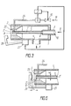
- Fig. I in schematischer Darstellung den erfindungsgemässen Flüssigkeitszerstäuber mit Systemen für die Druckgas- und Betriebsflüssigkeitszuführung und einem Reinigungssystem;
- Fig. 2 denselben (Variante), bei dem die Rohrleitung flexibel ausgeführt und mit einem hohlen beweglichen Element verbunden ist;
- Fig. 3 denselben (andere Variante), bei dem die Rohrleitung mit dem die Betriebsflüssigkiit zuführenden Kanal des Stutzens in Verbindung steht;
- Fig. 4 die gegenseitige Anordnung des hohl ausgebildeten beweglichen Elementes und des Stutzens beim Durchblasen des Mittels zur Betriebsflüssigkeitszuführung;
- Fig. 5 dasselbe beim Waschen des Mittels zur Betriebsflüssigkeitszuführung;
- Fig. 6 die gegenseitige Anordnung des beweglichen Elementes und des Stutzens beim gleichzeitigen Durchblasen und Waschen des Mittels zur Betriebsflüssigkeitszuführung.
- Fig. I in a schematic representation of the liquid atomizer according to the invention with systems for pressurized gas and operating fluid supply and a cleaning system;
- Figure 2 the same (variant), in which the pipeline is flexible and connected to a hollow movable element.
- 3 shows the same (different variant), in which the pipeline is connected to the duct of the connecting piece which supplies the operating liquid;
- Figure 4 shows the mutual arrangement of the hollow movable element and the nozzle when blowing through the means for operating fluid supply.
- 5 shows the same when washing the agent for supplying operating fluid;
- Fig. 6 shows the mutual arrangement of the movable element and the nozzle while blowing through and washing the agent for supplying operating fluid.
Der Flüssigkeitszerstäuber enthält ein Gehäuse I (Fig. I) das eine Düse 2 besitzt, die mit einem System 3 für die Druckgaszufuhr über eine Öffnung 4 im Gehäuse I in Verbindung steht. Der Zerstäuber enthält auch ein im Gehäuse I angeordnetes Mittel 5 zur Betriebsflüssigkeitszuführung in die Düse 2, welches mit einem System 6 für die Betriebsflüssigkeitszuführung in Verbindung steht und einen Stutzen 7 besitzt, dessen ein Ende 8 sich im Kanal 2' der Düse 2, der mit dem Kanal 7' des Stutzens 7 gleichachsig ist, befindet und das andere Ende mit einem Kanal 10 in Verbindung steht, welcher die Betriebsflüssigkeit von dem System 6 für die Betriebsflüssigkeitszuführung zuführt.The liquid atomizer contains a housing I (FIG. I) which has a
Als Betriebsflüssigkeit verwendet man Gele, Suspensionen, Lacke, Farben u.dgl.Gels, suspensions, lacquers, paints and the like are used as the operating fluid.
Die Abmessungen und die Form der Düse werden in Abhängigkeit von Betriebsbedingungen und Betriebsweisen (Arten von zu zerstäubenden Flüssigkeiten, Gasdruc,, Geschwindigkeit des Strahls usw.) ausgelegt.The dimensions and shape of the nozzle are dependent on operating conditions and modes of operation (types of liquids to be atomized, gas pressure, speed of the jet etc.) designed.
Der Zerstäuber enthält ferner ein System 11 für die Reinigung des Mittels 5 zur Betriebsflüssigkeitszuführung in die Düse 2 und einen Geber 12 für das Vorhandensein der Betriebsflüssigkeit im Stutzen 7, welcher Geber mit einem Steuerblock 13 zur Steuerung des Systems 11 für die Reinigung des Mittels 5 verbunden ist.The atomizer also contains a
Gemäss der Erfindung enthält das System 11 für die Reinigung des Mittels 5 zur Betriebsflüssigkeitszuführung in die Düse eine Rohrleitung 14 (Fig. 2) zur Waschflüssigkeitszuführung, die ein Überströmventil 15 besitzt, welches mit einem System 16 für die Waschflüssigkeitszuführung in Verbindung steht.According to the invention, the
Als Waschflüssigkeit kommen Wasser, organische Lösungsmittel, Waschmittel u.dgl. in Abhängigkeit von den Eigenschaften der verwendeten Betriebsflüssigkeit und des Materials, aus welchem die Einzelteile des Zerstäubers gefertigt sind, zur Anwendung.Water, organic solvents, detergents and the like come as washing liquid. depending on the properties of the operating fluid used and the material from which the individual parts of the atomizer are made.
Das Reinigungssystem 11 enthält auch ein auf der Aussenseite des Zerstäubergehäuses I angeordnetes bewegliches Element 17, das an einem Ende 17' mit einer Vorrichtung 18 zu seiner Verschiebung in Richtung zu dem im Kanal 21 der Düse 2 untergebrachten Ende 8 des Stutzens 7 in Verbindung steht. Dabei weist das freie Ende 17° des beweglichen Elementes 17 einen Querschnitt grösser als der Querschnitt des Stutzens 7 auf. Im vorliegenden Fall ist das bewegliche Element 17 in Form eines hohlen zylindrischen Rohres mit einem Aussendurchmesser D ausgeführt, der grösser als der Aussendurchmesser d des Stutzens 7 ist.The
Der Steuerblock 13 zur Steuerung des Reinigungssystems 11 ist mit der Verschiebevorrichtung 18 verbunden.The
In Fig. 2 ist eine Ausführungsvariante des Zerstäubers dargestellt, bei dem die Rohrleitung 14 flexibel ausgeführt und mit dem beweglichen Element 17 verbunden ist, das hohl ausgebildet ist. Hierbei ist der Geber 12 für das Vorhandensein der Betriebsflüssigkeit im Stutzen 7 im Kanal 7' des letzteren untergebracht.FIG. 2 shows an embodiment variant of the atomizer in which the
Die Vorrichtung 18 zur Verschiebung des beweglichen Elementes enthält eine am Gehäuse des Zerstäubers starr befestigte Buchse 19, die mit Nuten 20 zum Bewegen in ihnen von Führungen 21 mit dem an denselben befestigten beweglichen Element 17 versehen ist, und einen Stock 22, der an dem einen Ende mit dem beweglichen Element 17 und an dem anderen Ende mit dem Antrieb 23 der Vorrichtung 18 zu seiner Verschiebung verbunden ist. Der Vorteil dieser Konstruktion der Verschiebevorrichtung 18 liegt darin, dass sie einfach in der Herstellung ist und sich durch die Austauschbarkeit von Bauteilen auszeichnet; allerdings kann die Konstruktion dieser Vorrichtung anders sein, die jedoch dieselbe Aufgabe erfüllt.The
In Fig. 3 ist eine andere Ausführungsvariante des Zerstäubers dargestellt. Bei dieser Variante steht im Reinigungssystem II des Zerstäubers eine Rohrleitung 24 mit dem Kanal 7' des Stutzens 7 über eine an der Seitenfläche des Stutzens 7 ausgeführte Bohrung 25 in Verbindung, die sich neben dem im Kanal 21 der Düse 2 untergebrachten Ende 8 des Stutzens 7 befindet. Der Steuerblock 13 zur Steuerung des Reinigungssystems II ist mit dem Überströmventil 15 verbunden, wobei der Geber 12 für das Vorhandensein der Betriebsflüssigkeit im Stutzen 7 als Druckgeber ausgebildet und an der Rohrleitung 24 angebracht ist.Another variant of the atomizer is shown in FIG. In this variant, in the cleaning system II of the atomizer, a
Bei dieser Variante steht ein bewegliches Element 26 ebenfalls mit einer Vorrichtung 27 zu dessen Verschiebung in Verbindung, die ähnlich wie in der vorhergehenden Variante oder auf eine beliebige bekannte Weise zur Erreichung dieses Ziels ausgeführt werden kann.In this variant, a
Der erfindungsgemässe Zerstäuber arbeitet folgendermassen.The atomizer according to the invention works as follows.
Bei der Betriebsflüssigkeitszuführung in die Düse 2 über den Stutzen 7 und der Druckgaszufuhrüber die im Gehäuse I vorhandene Öffnung 4 bildet sich in der Düse 2 infolge der dynamischen Zusammenwirkung der Flüssigkeit mit dem Hochgeschwindigkeits-Gasstrom ein Aerosolstrom. Der Aerosolstrom wird auf Erzeugnisse zwecks deren Bearbeitung geleitet. Im Falle einer Verstopfung des Stutzens 7 oder des Kanals 10 hört die Betriebsflüssigkeitszuführung aus dem System 6 über den Kanal 10 in das Mittel 5 auf.When the operating fluid is fed into the
In diesem Fall spricht der Geber 12 an und schickt ein Signal auf den Steuerblock 13.In this case, the
Die Reinigung des Kanals 7' des Stutzens 7 und des Kanals 10 des Zerstäubers, dessen Variante in Fig. 2 angeführt ist, kommt folgenderweise zustande. Das Signal vom Steuerblock 13 gelangt an die Vorrichtung 18 zur Verschiebung des beweglichen Elementes 17. Durch Bewegen des Stocks 22 durch den Antrieb 23 wird das bewegliche Element 17 über die Führungen 21 durch die Buchse 19 hindurch aus der Aussenzone der Gasdüse 2 in den Kanal 21 in Richtung zum Ende 8 des Stutzens 7 hin so lange vorgeschoben, bis das freie Ende 17" des beweglichen Elementes 17 in einem gewissen Abstand I (Fig. 4) von dem Ende 8 des Stutzens 7 zu stehen kommt.The cleaning of the channel 7 'of the
Der genannte Abstand 1 wird gleich dem Aussendurchmesser d des Stutzens 7 gewählt. Der hierbei (infolge der Bremsung des Gasstromes) entstehende erhöhte Gasdruck bei dem Ende 8 des Stutzens 7 begünstigt das Durchblasen seines Kanals 7' und des Kanals 10. Experimentell wurde festgestellt, dass bei einem Abstand I grösser als der Durchmesser d das Durchblasen sehr schwach vor sich geht oder überhaupt nicht zu verzeichnen ist, während bei einem Abstand I kleiner als der Durchmesser d das Durchblasen zu intensiv geschieht, was eine Beschädigung der Wände des Stutzens 7 herbeiführen kann, wobei auch ein starkes Aufquellen der Betriebsflüssigkeit in dem (in Fig. nicht gezeigten) Verbrauchstank des Systems 6 für die Betriebsflüssigkeitszuführung beobachtet werden kann.The distance 1 mentioned is chosen equal to the outer diameter d of the
Bei dem Abstand I gleich d ist die Reinigung am effektivsten.The cleaning is most effective when the distance I is equal to d.
Zum Zwecke der Erzeugung des genannten erhöhten Drucks wird der Durchmesser D des freien Endes 17" des beweglichen Elementes 17 um das 1,5- bis 1,8fache grösser als der Durchmesser d des Stutzens 7 gewählt.For the purpose of generating the above-mentioned increased pressure, the diameter D of the
Nach der Einstellung des beweglichen Elementes 17 in die vorgegebene Lage erteilt der Steuerblock 13 zwecks Durchführung des Durchblasens des Kanals 7' des Stutzens 7 und des Kanals 10 einen nächstfolgenden Befehl an die Vorrichtung 18 zur Verschiebung des beweglichen Elementes 17, und es findet die weitere Verschiebung des beweglichen Elementes 17 bis zur Vereinigung desselben mit der Stirnfläche des Stutzens 7 (Fig. 5) auf der Seite des Endes 8 statt. Bei dieser Lage öffnet sich das Überströmventil 15, und die Waschflüssigkeit wird unter Druck aus dem System 16 für die Waschflüssigkeitszuführung den Kanälen 10 und 7 zugeführt, wodurch deren Waschen erfolgt. Nach Beendigung des Waschens kehrt das bewegliche Element 17 in die Ausgangslage (Fig. 2) zurück, wobei gleichzeitig mit Hilfe des Ventils 15 die Waschflüssigkeitszuführung abgesperrt wird.After setting the
In der anderen Ausführungsvariante des Zerstäubers, die in Fig. 3 dargestellt ist, entsteht bei einer Verstopfung des Zuführungskanals 10 und des Kanals 7' des Stutzens 7 wegen einer Ejektion des das Ende 8 des Stutzens 7 umfliessenden Gasstromes ein Unterdruck in der Rohrleitung 24. Dabei reagiert der Geber 12 für das Vorhandensein der Betriebsflüssigkeit auf die genannten Druckänderung und liefert ein Signal auf den Steuerblock 13, von welchem aus ein Signal an das Überströmventil 15 und die Vorrichtung 27 zur Verschiebung des beweglichen Elementes 26 gelangt.In the other embodiment variant of the atomizer, which is shown in FIG. 3, if the
Infolgedessen hört die Zuführung der Betriebsflüssigkeit aus dem System 6 auf, während sich das bewegliche Element 26 zum Ende 8 des Stutzens 7 hin verschiebt und sich in einem Abstand 11 (Fig. 6) von ihm einstellt, der ungefähr dem Durchmesser d des Stutzens 7 gleich ist. Daraufhin findet das Durchblasen statt. Gleichzeitig mit diesem Signal vom Steuerblock 13 öffnet sich das Überströmventil 15, und die Waschflüssigkeit wird vom System 16 über die Rohrleitung 24 durch die seitliche Bohrung 25 dem Kanal 7' des Stutzens 7 zugeführt, so dass auf diese Weise das Waschen der Kanäle 7 und 10 stattfindet. Es sei bemerkt, dass das bewegliche Element 26 während des Waschvorgangs in die Aussenzone der Gasdüse 2 nicht zurückkehrt, und daher geht gleichzeitig das Durchblasen und Waschen vonstatten, was zu einer effektiveren Reinigung des Mittels 5 beiträgt.As a result, the supply of the operating fluid from the
Nach Beendigung des Waschens wird vom Steuerblock 13 ein Signal an die Verschiebevorrichtung 27 und das Überströmventil 15 abgegeben, wodurch das bewegliche Element 26 in die Ausgangslage zurückkehrt, während sich das Überströmventil 15 schliesst und die Zuführung der Betriebsflüssigkeit unterbindet.After washing has ended, the
Der erfindungsgemässe Flüssigkeitszerstäuber besitzt dank der konstruktiven Lösung eine hohe Leistung und sichert eine hohe Qualität der Zerstäubung verschiedener Flüssigkeiten.Thanks to the constructive solution, the liquid atomizer according to the invention has a high performance and ensures a high quality of the atomization of various liquids.
Am effektivsten kann die Erfindung in der Flugzeugindustrie, Kraftfahrzeugindustrie, im Werkzeug-und Vorrichtungsbau, in der Papierindustrie und in anderen Industriezweigen für die Zerstäubung von Gelen, Suspensionen, Trüben angewendet werden.The invention can be most effectively applied to the aerospace, automotive, tool and fixture, paper, and other industries for the atomization of gels, suspensions, slurries.
Ausserdem kann die Erfindung zur Zerstäubung von Lacken, Farben, kolloidalen Lösungen beim Auftragen von dekorativen und speziellen Schutzüberzügen zur Anwendung kommen.In addition, the invention can be used to atomize lacquers, paints, colloidal solutions when applying decorative and special protective coatings.
Claims (4)
Applications Claiming Priority (4)
| Application Number | Priority Date | Filing Date | Title |
|---|---|---|---|
| SU4784171 | 1990-02-05 | ||
| SU904784171A RU1771818C (en) | 1990-02-05 | 1990-02-05 | Liquid sprayer |
| SU4855987 | 1990-06-30 | ||
| SU4855987 RU1819683C (en) | 1990-07-30 | 1990-07-30 | Atomizer of liquid |
Publications (2)
| Publication Number | Publication Date |
|---|---|
| EP0466943A1 true EP0466943A1 (en) | 1992-01-22 |
| EP0466943A4 EP0466943A4 (en) | 1992-07-01 |
Family
ID=26666227
Family Applications (1)
| Application Number | Title | Priority Date | Filing Date |
|---|---|---|---|
| EP19910903926 Withdrawn EP0466943A4 (en) | 1990-02-05 | 1990-12-07 | Liquid pulverizer |
Country Status (2)
| Country | Link |
|---|---|
| EP (1) | EP0466943A4 (en) |
| WO (1) | WO1991011266A1 (en) |
Cited By (7)
| Publication number | Priority date | Publication date | Assignee | Title |
|---|---|---|---|---|
| DE19814491A1 (en) * | 1998-04-01 | 1999-10-07 | Voith Sulzer Papiertech Patent | Blockage prevention method for dosing gap of spray nozzle appliance |
| US7947199B2 (en) | 2005-03-02 | 2011-05-24 | Ormecon Gmbh | Conductive polymers consisting of anisotropic morphology particles |
| US7989533B2 (en) | 2005-08-19 | 2011-08-02 | Ormecon Gmbh | Chemical compound comprising an indium-containing intrinsically conductive polymer |
| EP2349581A1 (en) * | 2008-07-14 | 2011-08-03 | Kim Lui So | Method and apparatus for maintaining a fluid supply |
| US8153271B2 (en) | 2006-09-13 | 2012-04-10 | Ormecon Gmbh | Article with a coating of electrically conductive polymer and precious/semiprecious metal and process for production thereof |
| US8344062B2 (en) | 2004-01-23 | 2013-01-01 | Ormecon Gmbh | Dispersions of intrinsically conductive polymers |
| CN111013837A (en) * | 2019-11-12 | 2020-04-17 | 河北华丰能源科技发展有限公司 | Spray head and spraying system |
Families Citing this family (2)
| Publication number | Priority date | Publication date | Assignee | Title |
|---|---|---|---|---|
| US5351886A (en) * | 1993-02-11 | 1994-10-04 | Bull Dan F | Self-cleaning shower nozzle system |
| WO1996003219A1 (en) * | 1994-07-25 | 1996-02-08 | Nordson Corporation | System for cleaning accumulation on powder spray gun |
Citations (1)
| Publication number | Priority date | Publication date | Assignee | Title |
|---|---|---|---|---|
| DE2854325A1 (en) * | 1978-12-15 | 1980-06-19 | Mueller Ernst & Co | Rinser for fluid spray appliances - uses cup-shaped catch cylinder turned-up over spray head and connected to drain pipe |
Family Cites Families (3)
| Publication number | Priority date | Publication date | Assignee | Title |
|---|---|---|---|---|
| CS242610B1 (en) * | 1982-11-19 | 1986-05-15 | Miloslav Sorm | Double acting mechanical pump for liquid spray |
| GB8527244D0 (en) * | 1985-11-05 | 1985-12-11 | Roberts G S | Cleaning spray painting guns |
| SU1479122A1 (en) * | 1987-04-27 | 1989-05-15 | Предприятие П/Я А-1080 | Spray gun for quick-curing two-component mixtures |
-
1990
- 1990-12-07 WO PCT/SU1990/000271 patent/WO1991011266A1/en not_active Application Discontinuation
- 1990-12-07 EP EP19910903926 patent/EP0466943A4/en not_active Withdrawn
Patent Citations (1)
| Publication number | Priority date | Publication date | Assignee | Title |
|---|---|---|---|---|
| DE2854325A1 (en) * | 1978-12-15 | 1980-06-19 | Mueller Ernst & Co | Rinser for fluid spray appliances - uses cup-shaped catch cylinder turned-up over spray head and connected to drain pipe |
Non-Patent Citations (1)
| Title |
|---|
| See also references of WO9111266A1 * |
Cited By (9)
| Publication number | Priority date | Publication date | Assignee | Title |
|---|---|---|---|---|
| DE19814491A1 (en) * | 1998-04-01 | 1999-10-07 | Voith Sulzer Papiertech Patent | Blockage prevention method for dosing gap of spray nozzle appliance |
| US8344062B2 (en) | 2004-01-23 | 2013-01-01 | Ormecon Gmbh | Dispersions of intrinsically conductive polymers |
| US7947199B2 (en) | 2005-03-02 | 2011-05-24 | Ormecon Gmbh | Conductive polymers consisting of anisotropic morphology particles |
| US7989533B2 (en) | 2005-08-19 | 2011-08-02 | Ormecon Gmbh | Chemical compound comprising an indium-containing intrinsically conductive polymer |
| US8153271B2 (en) | 2006-09-13 | 2012-04-10 | Ormecon Gmbh | Article with a coating of electrically conductive polymer and precious/semiprecious metal and process for production thereof |
| EP2349581A1 (en) * | 2008-07-14 | 2011-08-03 | Kim Lui So | Method and apparatus for maintaining a fluid supply |
| EP2349581A4 (en) * | 2008-07-14 | 2013-03-13 | Kim Lui So | Method and apparatus for maintaining a fluid supply |
| CN111013837A (en) * | 2019-11-12 | 2020-04-17 | 河北华丰能源科技发展有限公司 | Spray head and spraying system |
| CN111013837B (en) * | 2019-11-12 | 2021-06-15 | 河北华丰能源科技发展有限公司 | Spray head and spraying system |
Also Published As
| Publication number | Publication date |
|---|---|
| WO1991011266A1 (en) | 1991-08-08 |
| EP0466943A4 (en) | 1992-07-01 |
Similar Documents
| Publication | Publication Date | Title |
|---|---|---|
| DE4230535C2 (en) | Two-component spray gun | |
| EP0865830B1 (en) | Colour changer with reversible direction of paint flow | |
| DE4330602A1 (en) | Rotary atomizing device for electrostatic coating and method for using the same | |
| EP2976158A1 (en) | Spraying device, quick-change adapter | |
| DE4136000A1 (en) | METHOD FOR CLEANING SPRAY COATING DEVICES | |
| EP2089164B2 (en) | Universal atomizer, and associated operating method | |
| DE69827611T2 (en) | COATING DEVICE WITH A TURNING SPRAY HEAD | |
| DE10139088A1 (en) | Robot arm with paint atomizer attachment has part of unit to which line fitting is attached able to rotate relative to first component member | |
| EP0466943A1 (en) | Liquid pulverizer | |
| EP0105493A2 (en) | Nozzle for a spray-gun, especially for a low-pressure spray-gun | |
| EP2929944A1 (en) | Dye spraying device | |
| EP2056970B2 (en) | Cleaning apparatus for sprayers, in particular spray guns, and method for cleaning a sprayer | |
| EP0664161A1 (en) | Device for spraying liquids, particularly paints | |
| DE4223006C2 (en) | Device for treating workpieces with a pressure fluid | |
| DE3613348C2 (en) | ||
| CH642572A5 (en) | SELF-CLEANING SPRAY NOZZLE ON A SPRAYING DEVICE. | |
| DE3120260C2 (en) | ||
| DE102013003897B4 (en) | Nozzle carrier for the attachment of a Lackierdüse to a Lackzerstäubereinrichtung and Lackzerstäubereinrichtung with such a nozzle carrier | |
| DE102019110188A1 (en) | Multi-fluid nozzle, in particular two-fluid nozzle | |
| DE3137074C2 (en) | System for the electrostatic coating of workpieces with a liquid | |
| DE19721650C2 (en) | Device for aerosol production | |
| DE3542710A1 (en) | Apparatus for the feed of paint powder in powder coating | |
| DE3237148C2 (en) | Pneumatically controlled paint spray gun | |
| DE7907727U1 (en) | SPRAY GUN | |
| DE102011116745A1 (en) | Spraying nozzle device for industrial robot for automatic coating of cavities of motor vehicle body with air wax mixture, has channel corresponding to spraying nozzle in application position and connected to corrosion inhibiter supply |
Legal Events
| Date | Code | Title | Description |
|---|---|---|---|
| PUAI | Public reference made under article 153(3) epc to a published international application that has entered the european phase |
Free format text: ORIGINAL CODE: 0009012 |
|
| 17P | Request for examination filed |
Effective date: 19910923 |
|
| AK | Designated contracting states |
Kind code of ref document: A1 Designated state(s): CH DE FR GB LI |
|
| A4 | Supplementary search report drawn up and despatched |
Effective date: 19920513 |
|
| AK | Designated contracting states |
Kind code of ref document: A4 Designated state(s): CH DE FR GB LI |
|
| STAA | Information on the status of an ep patent application or granted ep patent |
Free format text: STATUS: THE APPLICATION IS DEEMED TO BE WITHDRAWN |
|
| 18D | Application deemed to be withdrawn |
Effective date: 19930701 |