EP0466821B1 - Selective active overt comfort system - Google Patents
Selective active overt comfort system Download PDFInfo
- Publication number
- EP0466821B1 EP0466821B1 EP90906613A EP90906613A EP0466821B1 EP 0466821 B1 EP0466821 B1 EP 0466821B1 EP 90906613 A EP90906613 A EP 90906613A EP 90906613 A EP90906613 A EP 90906613A EP 0466821 B1 EP0466821 B1 EP 0466821B1
- Authority
- EP
- European Patent Office
- Prior art keywords
- belt
- tension
- relieving
- pawl
- ratchet
- Prior art date
- Legal status (The legal status is an assumption and is not a legal conclusion. Google has not performed a legal analysis and makes no representation as to the accuracy of the status listed.)
- Expired - Lifetime
Links
- 230000000903 blocking effect Effects 0.000 claims description 8
- 230000007246 mechanism Effects 0.000 abstract description 22
- 230000004913 activation Effects 0.000 abstract description 2
- 230000006870 function Effects 0.000 abstract description 2
- 230000004075 alteration Effects 0.000 description 2
- 238000004519 manufacturing process Methods 0.000 description 2
- 230000004048 modification Effects 0.000 description 2
- 238000012986 modification Methods 0.000 description 2
- 230000009471 action Effects 0.000 description 1
- 230000000712 assembly Effects 0.000 description 1
- 238000000429 assembly Methods 0.000 description 1
- 239000011324 bead Substances 0.000 description 1
- 230000008878 coupling Effects 0.000 description 1
- 238000010168 coupling process Methods 0.000 description 1
- 238000005859 coupling reaction Methods 0.000 description 1
- 238000007373 indentation Methods 0.000 description 1
- 230000014759 maintenance of location Effects 0.000 description 1
Images



Classifications
-
- B—PERFORMING OPERATIONS; TRANSPORTING
- B60—VEHICLES IN GENERAL
- B60R—VEHICLES, VEHICLE FITTINGS, OR VEHICLE PARTS, NOT OTHERWISE PROVIDED FOR
- B60R22/00—Safety belts or body harnesses in vehicles
- B60R22/34—Belt retractors, e.g. reels
- B60R22/44—Belt retractors, e.g. reels with means for reducing belt tension during use under normal conditions
-
- B—PERFORMING OPERATIONS; TRANSPORTING
- B60—VEHICLES IN GENERAL
- B60R—VEHICLES, VEHICLE FITTINGS, OR VEHICLE PARTS, NOT OTHERWISE PROVIDED FOR
- B60R22/00—Safety belts or body harnesses in vehicles
- B60R22/34—Belt retractors, e.g. reels
- B60R22/44—Belt retractors, e.g. reels with means for reducing belt tension during use under normal conditions
- B60R2022/4486—Belt retractors, e.g. reels with means for reducing belt tension during use under normal conditions for cancelling the belt tension
-
- B—PERFORMING OPERATIONS; TRANSPORTING
- B60—VEHICLES IN GENERAL
- B60R—VEHICLES, VEHICLE FITTINGS, OR VEHICLE PARTS, NOT OTHERWISE PROVIDED FOR
- B60R22/00—Safety belts or body harnesses in vehicles
- B60R22/34—Belt retractors, e.g. reels
- B60R22/44—Belt retractors, e.g. reels with means for reducing belt tension during use under normal conditions
- B60R2022/4493—Belt retractors, e.g. reels with means for reducing belt tension during use under normal conditions for braking the belt reel using friction surfaces or the like
Definitions
- the invention relates to a safety belt system having a tension-relieving mechanism and more specifically to such a system in which the tension is relieved by a deliberate manual actuation of a control switch, lever or other actuator.
- the usual tension-relieving mechanism is placed into the tensionless or comfort mode by the wearer having extended the seat belt about his torso and shoulder and then pulling the seat belt to further protract the belt, followed by a release of the belt for a slight belt rewind movement.
- This sequence causes an internal locking pawl to engage a ratchet wheel fixed to the reel shaft to prevent continued rewinding of the belt onto the reel under the force of the reel rewinding biasing means.
- a vehicle occupant's shoulder is relieved of the force of the rewind spring acting to rewind the shoulder belt.
- Such devices are shown in U.S. Patent Nos. 3,851,836; 3,869,098 and 3,834,646.
- Conventional tensionless mechanisms generally have a memory system, which allows the occupant to move slightly forward to extract one or two inches of seat belt from the retractor without cancelling the tensionless mode.
- the tension-relieving pawl again becomes engaged with the ratchet wheel to relieve the tension.
- the tension-relieving mechanism is automatically shifted to its ineffective or release position, causing the seat belt to tightly rewind against the occupant; or if the occupant opens the vehicle door, the seat belt rewinds to its fully wound position on the seat belt reel.
- a door-operated release means senses the opening of the door and shifts the tension-relieving mechanism to its release state, if it is already not there, thereby causing a rewind of the belt to its fully wound position on a reel.
- the system is set into its tensionless state by the occupant actuating a means such as a switch, which closes a circuit to operate a solenoid to shift the locking pawl into locking engagement with the ratchet wheel to immediately place the tensionless system into its tension-relieving state irrespective of occupant location.
- a means such as a switch
- This is in contrast to usual non-electrical tensionless systems, in which a belt protraction is required to set the tensionless device into a tensionless mode.
- an electrically operated-tensionless system such as disclosed in U.S. Patent No. 4,585,185, can only be released by a subsequent electrical operation of a switch means.
- US-A-4669751 discloses a safety belt retractor mechanism for vehicle passengers having an apparatus for selectively relieving belt retractive tension on the passenger in accordance with the preamble of claim 1.
- the apparatus may be either manually or automatically engaged at a first extensive position of the belt corresponding to the buckled up position such that, for a single extractive movement of the belt by a first predetermined amount of 'slack', the belt is locked against further retractive movement below that position, thereby relieving the retractive tension of the belt on the wearer.
- the present invention is directed to providing a manual overt actuator tensionless system requiring the operator to make a conscious decision to operate the actuator, which is usually in the form of a switch or lever, to set the tensionless device in an activated state and to also make a slight protraction of the belt that places the device into a tensionless state to relieve the belt tension on the occupant's shoulder.
- the actuator which is usually in the form of a switch or lever
- the tensionless device in an activated state and to also make a slight protraction of the belt that places the device into a tensionless state to relieve the belt tension on the occupant's shoulder.
- the present invention also provides a memory to return to the tensionless state if the belt is only protracted a short distance and then released. If the belt is protracted beyond the memory distance, the tensionless mechanism automatically is shifted into its release state allowing belt retraction.
- the tensionless mechanism may be released by another disengaging or operating means connected to a vehicle door, which means actuates rewinding of the seat belt automatically to its fully wound state upon opening the associated vehicle door.
- the present invention provides a tensionless system that requires an overt actuation by the seat occupant of an actuator, followed by the usual belt manipulations to shift the tensionless mechanism to its tension-relieving state.
- the present invention also provides for a memory system which allows belt protraction of less than a predetermined length with a return to the tensionless position so long as the predetermined memory length is not withdrawn. In the tension-relieving position, a belt protraction beyond the short, predetermined memory distance results in disengagement of the tensionless device.
- the present invention not only provides new and improved functions, but is also inexpensive to manufacture and small in size, which avoids interference with existing seat belt retractor placements.
- the invention provides a seat belt retractor for rewinding a seat belt, said retractor comprising: a reel; a first biasing means for biasing the reel to retract and to rewind the belt on the reel; an emergency locking means for locking the belt against protraction at the time of an accident; a tension-relieving means for relieving a tension force positionable in a tension-relieving position applied by the belt onto an occupant body in a vehicle by blocking belt retraction and rewinding movement of the reel and positionable in a release position in which the tension-relieving means is inoperable from relieving belt tension; the tension-relieving means including a pawl and a ratchet means which is connected to the reel and rotatable therewith until the pawl is in blocking engagement with the ratchet means; a manual overt actuator for shifting the tension-relieving means to an activated position from which said tension-relieving means may be shifted to the tensionless position by belt protraction; means operable by belt protraction beyond
- the present invention provides a manually-operated, overt actuator tensionless system which requires a slight belt protraction to set the system in its tensionless state. That is, the system requires an overt, manual, activation of an actuator by a seat occupant, followed by belt manipulations to engage the tensionless or belt-tension relieving mechanism to the tensionless state or position.
- the mechanism is initially slightly displaced to an activated state or position and subsequently protraction of the belt transfers the belt to the tensionless state, which preferably has a "memory", that is, protraction of the belt beyond the tensionless mode a short distance but less than a predetermined distance will allow the belt to return to the tensionless state.
- belt protraction beyond the predetermined distance will result in disengagement of the belt from the tensionless mode and reversion to the reference, that is belt-tensioned, mode.
- the mechanism for the tensionless system is relatively compact and incorporates components which are easily manufactured and not subject to excessive wear.
- the assembly lends itself to adoption to a retractor assembly and has an easily operated overt manual actuator, as well as an automatic (door) operator. All of the above assets and attributes of the mechanism are in addition to the primary goal of providing a vehicle occupant with a safe seat belt retractor requiring a conscious act with a manual actuator and belt manipulation to engage the tensionless state, but limits the tensionless tate to an acceptable range before an automatic return to the tensioned belt mode.
- the present invention broadly relates to a seat belt retractor system generally utilized in automobile safety systems. More particularly, the invention provides a retractor having a manually-engageable tensionless or tension-relieving mode in the retractor system.
- FIG. 12 there is illustrated a typical seat system which is an automatic system for applying a lap belt and a shoulder belt to the occupant upon a closing of the door.
- Retractor 10 includes a belt 12 wound on a webbing reel 14 mounted on shaft 16, and a tensionless or tension-relieving means 18 mounted at one end 20 of shaft 16 for operation with reel 14.
- a rewind or biasing means or spring 22 is illustrated at the second or other end 23 of shaft 16, which spring 22 biases the reel 14 and belt 12 to the rewound position.
- Retractor assemblies for rewinding safety belts generally include an emergency locking mechanism 25, broadly shown in dashed outline, which may be of the inertia type operable by a pendulum weight 27 mounted on a support bar to actuate and lock the retractor mechanism against belt protraction during a vehicle accident or other sudden deceleration.
- a locking mechanism is illustrated and discussed in U.S. Patent No. 4,361,294 at FIG. 1.
- the tension-relieving means 18 is manually operated into the tension-relieving state or mode by operation of an overt manual actuator 62 which may be in the form of a button or lever positioned near the occupant to move a control cable 70 (FIGS. 2 and 7) or it may be in the form of a manually operated, electrical switch (not shown) to activate a solenoid plunger to move an actuator or to shift the tension-relieving means 18 from its non-activated state.
- an overt manual actuator 62 which may be in the form of a button or lever positioned near the occupant to move a control cable 70 (FIGS. 2 and 7) or it may be in the form of a manually operated, electrical switch (not shown) to activate a solenoid plunger to move an actuator or to shift the tension-relieving means 18 from its non-activated state.
- Such systems often did not have a memory feature or a manual belt manipulation release, which could be activated by pulling the belt out beyond the memory distance.
- the tension-relieving means 18 may be actuated by operation of the overt manual actuator 62, which shifts the tension-relieving means 18 to an activated or primed state (cf. FIG 2A); and thereafter a slight belt protraction, automatically shifts the tension-relieving means 18 into the tension-relieving position, as shown in FIG. 4, in which nose 148 of tension-relieving pawl 58 engages teeth 42 on ratchet wheel 40, which is fixed by fingers 45 to reel shaft 16, to hold it against turning in the rewind direction (cf. arrow in FIG. 4) as urged by the reel spring 22.
- the tensionless means 18 has a memory position or state with pawl 58 held above the teeth 42 by a cam surface 92 on first rotatable member or lock control disc 50. So long as belt 12 is not protracted beyond the memory distance, pawl 58 will be returned into engagement with ratchet teeth 42 to reestablish the tension-relieving state. However, belt protraction beyond the memory distance causes tab means 98 to move into its detented or reference position (FIG. 5) to hold the lock control disc 50 with its cam surface 92 holding pawl 58 from engaging ratchet wheel 40, thus allowing belt 12 to rewind on reel 14.
- the remote door actuator 64 shifts an actuator cable or plunger 79 to shift unlocking member 38 to cam pawl 58 from engagement with teeth 42 on ratchet wheel 40 (cf. FIG. 2), which allows belt 12 to fully rewind when the occupant leaves the vehicle.
- the tension-relieving means 18 has a housing or cover 24, which housing or cover is generally cup-shaped with a cavity 26 to receive the pawl and ratchet mechanism as well as the control discs.
- Housing 24 is illustrated as circular-shaped, as an example and not a limitation, with cover face 28 having a center location 30 (FIG. 4) and a central post 32 extending from inner surface 36 of cover 24 in cavity 26.
- Post 32 is concentric with a surrounding annulus 34, which also extends from inner surface 36 of cover 24 into cavity 26.
- Tensionless means 18 includes unlocking disc 38, which is mounted and operable on annulus 34.
- a ratchet wheel 40 with a plurality of ratchet teeth 42 and indentations, has a bore 44 to receive post 32 for rotatable mounting thereon.
- pawl 58 When pawl 58 is engaged with ratchet wheel 40, the ratchet wheel holds reel shaft 16 to secure the belt in the tensionless mode against the rewinding bias force of biasing means 22.
- a lock control disc or first rotatable member 50 is mounted concentrically with ratchet 40 and is biased for frictional engagement with a flange 41 of ratchet 40 by a disc spring or washer 52 to maintain contact with the frictional surface of ratchet 40.
- An actuator means 54 to shift the lock control disc with operation of the manual overt actuator, includes an extending arm 55, which is operable to engage or initiate the tensionless means 18 into the tensionless mode. The assembly 18 is shifted into the tensionless mode by actuating the first external or overt manual actuator 62 and is returned to its original release or detented position by a protraction of belt 12 beyond a predetermined distance.
- Manual overt actuator 62 has a bias means 62a, such as a spring, operable to return actuator 62 and arm 55 to the reference position.
- a second remote or disengaging apparatus 64 is also operable to disengage the retractor assembly from the tension mode, which remote disengaging apparatus 64 is generally operable by a vehicle door. That is, at door opening the door actuator or disengagement apparatus 64 actuates an unlocking disc 38 to disengage the pawl 58 from the ratchet wheel 40 to establish the tensionless mode of FIG. 2, thereby allowing retractor assembly 10 to rewind belt 12 at belt disengagement.
- Tensionless apparatus 18 is illustrated in FIGS. 2-11 in both exploded and plan views.
- the actuator means 54 shifts the lock control disc 50 to activate the tensionless device.
- Actuator means 54 includes a manual actuator, which is preferably in the form of a lever or a push button, which is biased by a spring 62a, to return to its initial position after manual overt actuation by the occupant, to move a cable 70 and thus a cylindrical cam 71 projecting from the end of the cable at a right angle thereto and forming a T-shaped end, which is fitted into a hollow bore 69 in an actuator cam lug 66 fixed to one side of a rotatable actuator pin 73.
- actuator pin is journaled to rotate about its longitudinal axis with one end of pin 73 journaled in a stationary member 75 fixed to cover 24, and the other end journaled in a bore in the cover 24.
- the pin 73 is thus rotatable with a push or pull of the cable 70, which turns the pin 73 to cause its internal cam end 68, which is of semicircular cross-section, to turn from the detent position of FIG. 5.
- tab 98 on the lock control disc 50 is in a space 76 between stationary detent shoulders 77 and 77a on the cover 24 and is movable to the activated position (FIG. 6) with tab 98 shifted to a position in which a pointed end 99 on the tab 98 has been lifted or translated from the space 76 and is positioned on a downward sloping surface of a ramp 72.
- actuator pin 73 As best seen in FIG. 5, turning of actuator pin 73 counterclockwise causes its upper edge 73a to move against inclined cam surface 98a on the tab 98 and to push the latter down and to the left, as viewed in FIG. 5, thereby lifting tab 98 from detent gap 76.
- This movement of tab 98 rotates disc 50 slightly to the position of FIG. 6, where tab point 99 is on the sloped surface of the up ramp 72, which positions lock control disc 50 in its activated state for movement into its tensionless position.
- the actuator spring 62a shifts the cable to turn the actuator pin 73 back to its centered position of FIG. 5.
- a subsequent protraction of the belt will rotate control disc 50 to move the tab point 99 further down the up ramp 72 and to position window 100 on control disc 50 under the pawl stud 141.
- the actuator means 54 could include an electrical switch operated by the occupant to cause a solenoid or other electrical actuator to shift the tab 98 from the detented position of FIG. 5 to the activated position shown in FIG. 6.
- Lock control disc or first rotatable member 50 is illustrated in FIGS. 10 and 11 with front surface 90, and a cam control circumference 92 engageable with pawl stud 141, a central bore 94, and a back surface 96.
- Disc 50 has the tab 98 which extends normally from back surface 96, and a slot or window 100 along circumference 92, which may be an arc-shaped slot to allow the stud 141 to drop and thereby lower the pawl to engage the ratchet wheel.
- An annular wall 102 extends from front surface 90 for frictional engagement and travel with a contact surface or flange 41 of ratchet 40. This frictional engagement comprises a friction clutch between the ratchet wheel and the lock control disc.
- Window 100 defines the limits of the tensionless mode per se.
- Unlocking disc 38 has an annular shape with a circumference cam surface 108 to hold the pawl stud 141 up, and to lift the pawl from the ratchet to allow automatic belt rewind.
- the unlocking disc 38 also has an outer surface 104, a central through-bore 106, and a groove 122 with shoulder 124, base 126 and ramp 128 sloped from base 126 to outer edge 108.
- Unlocking disc 38 is mounted in cavity 26 of housing 24 with annulus 34 extending through bore 106.
- Disc 38 has a sidewall 109 cooperating with inner surface 112 to define a partial cavity 110.
- the unlocking disc 38 is shifted, for example, by a door actuator mechanism 64, to rotate the cam surface 128 to cam upwardly the stud 141 which then rides on the cam circumferential surface 108, holding the pawl nose above the ratchet teeth, as shown in FIG. 2.
- the unlocking disc has a lug 114, which pivots downwardly, as the disc is rotated counterclockwise by the door actuator.
- the preferred and illustrated door actuator includes a spring-biased door plunger, which is pushed inwardly by the door as it swings closed and which is pulled by a spring as the door opens in a conventional manner.
- This door plunger is connected by a cable 79 to a T-end 81, which includes a cylindrical pin 83 which is received in a cylindrical bore 116 in the second lug 114 on the unlocking disc.
- the second lug 114 projects from surface 112 generally normally thereto and has the through-bore 116 extending in the longitudinal direction with an intersecting blind-hole cross-bore 118 to receive the cable and intersecting bore 116.
- Second lug 114 is coupled to and operable with external disengaging means 64 by coupling means 79 (cf. FIGS. 2, 4 and 7), which means 64 may be the door plunger or which may be an electrical switch operable by an automobile door during its opening and closing to operate a solenoid (not shown) to rotate the unlocking disc.
- Slot 122 is operable to receive the stud 141 of securing means 58, to allow the pawl to lower to engage the ratchet.
- Cover or housing 24, as illustrated in FIG. 7, has annulus or annulus members 34 and post 32 extending from inner surface 36.
- Cover 24 is generally cup-shaped and includes a plurality of mounting lugs 132 and a projecting mounting post or stud 134.
- Sidewall 136 cooperates with inner surface 36 to define cavity 26, which is generally operable to receive the assembly comprising tensionless or tension-relieving means 18.
- the up ramp 72 and the down ramp 74 are formed on the cover inner surface and project toward the ratchet wheel.
- the detent space 76 is located between shoulders 77 and 77a on the ramps 72 and 74.
- Securing means 58 in FIG. 7 is a pawl for engagement with ratchet teeth 42 or engagement in ratchet grooves of ratchet 40.
- Pawl 58 is shown as having a dogleg shape with a through-bore 130 at one end to receive mounting post 134, and pawl 58 is pivotable or rotatable thereon.
- Stud 141 extends generally normally from rear face 142 of pawl 58.
- Pawl 58 includes a bead 143 for maintaining pawl 58 in its pivotable position in retractor assembly 10.
- the assembly has ratchet 40 with hub 39, which is seated within annulus 34.
- ratchet 40 includes a central hub 39 about which are a plurality of teeth 42 engageable with pawl 58, which pawl 58 will restrain rewinding action of reel 14 by retention of the ratchet 40.
- disc spring 52 is mounted against annulus 34 and about hub 39 to bias the lock control disc 50 against the friction surface 43 of ratchet flange 41. Therefore, lock control disc 50 is normally biased to move and rotate with ratchet 40, which ratchet is mounted on shaft 16 with fingers 45 and rotatable with shaft 16.
- remote door actuator 64 moves lug 114 through connecting means 79 to rotate automatically-operable actuator or unlocking disc 38 into the position noted in FIG. 4 with groove 122 in position to receive stud 141 of pawl 58 when window 100 of disc 50 is aligned therewith.
- the tensionless device is inoperative and in its release state, with belt tension on the shoulder of the occupant.
- the lock control disc is detented with tab means 98 in the detent space 76 between ramps 72 and 74, as shown in FIG. 2.
- tab 98 is constrained between the ramp shoulders 77 and 77a, and the pawl 58 is raised with stud 141 on the cam surface 92 holding the pawl above the ratchet teeth 42 to maintain belt 12 in a tensioned state.
- the tensionless mode may be initiated by depression or actuation of manual overt actuator 62 to turn pin 73 to move the tab 98 and the lock control disc 50 axially inwardly toward the ratchet wheel 40 and to turn lock control disc clockwise to the activated position shown in FIG. 2A. That is, the activated state or mode is attained by the actuation of manual actuator 62 to rotate lug 66, arm 55 and end 68 to displace tab 98 from detent space 76 with tab point 99 on sloped surface 72, as seen in FIG. 6.
- lock control disc 50 which is biased by spring 22 in the rewinding direction, to move pawl stud 141 along lower surface 101 and up ramp 105 to circumference cam surface 92 to lift the pawl 58, and thereby be in the "memory" state. If belt protraction is less than the predetermined "memory" range of the cam surface 92, as the occupant leans back to allow belt rewind, lock control disc 50 will rotate in the rewinding direction to reengage the tensionless mode when window 100 and groove 122 are aligned to receive pawl stud 141 and to allow pawl end 148 to drop into engagement with one of ratchet teeth 42.
- Protraction beyond the predetermined memory range will rotate the lock control disc through a distance to cause the point 99 on the tab 98 to slide along the down ramp until the point slides off at shoulder 77a and moves toward the cover to again nest in detent space 76 and thereby resetting the tensionless device in its original tensioned and detented state.
- the tensionless state is defined by aligning the stud 141 with the groove 122 and window 100 to allow engagement of pawl end 148 with ratchet teeth 42.
- a belt 12 protraction which rotates the tab 98 less than the distance to reenter detent 76 with the cam surface 92 holding the stud 141 and pawl upwardly, allows the spring bias to act to rewind belt 12 and reposition window 100 in alignment with groove 122 to permit stud 141 to again nest therein for pawl 58 engagement with ratchet 40, thus reestablishing the tensionless mode.
- first rotatable member 50 has a generally circular shape with the arc-shaped window 100 at its circumference 92.
- inclined cam surface 105 cams stud 141 upwardly to the circumference cam surface 92.
- groove 122 on the unlocking disc is aligned for receipt of pawl stud 141 and when the unlocking disc 38 is rotated by the automatic operator 64, the inclined cam surface 128 of unlocking member 38 lifts stud 141 onto cam surface 108, and thereby the pawl from the ratchet, to cause automatic belt rewind.
- the tensionless mode per se is defined where window 100 is in alignment with groove 122 of automatically operable a actuator or unlocking disc 38, which alignment can receive pawl stud 141 for pawl end 148 engagement with ratchet teeth 42 for securing reel 14 from rewinding belt 12.
- Belt 12 includes a "memory" in the tensionless mode. That is, with pawl stud 141 nested in window 100 and groove 122, the belt 12 may be protracted a short distance, such as less than three to four inches, and thereafter returned to the tensionless setting.
- the memory position is achieved by protraction of belt 12, as seen in FIGS. 2, 4 and 7, in a clockwise rotation of ratchet 40 and first rotational member 50. This rotary motion of first rotational member 50 moves pawl stud 141 along lower surface 101 and inclined surface 105 of window 100, to ride along the circumference cam surface 92.
- an opening of the door actuates door actuator 64 to move connecting means 79, which is coupled to lug 114, to rotate the automatically-operable unlocking disc 38 about annulus 34.
- Rotation of disc 38 in a clockwise direction from the position shown in FIG. 4 will move upwardly-sloped ramp 128 to engage and to lift pawl stud 141 with the pawl 58 pivoting about pivot stud 134.
- Pawl 58 is lifted and disengaged from ratchet 40, which allows bias means 22 to urge reel 14 to rewind belt 12, and the belt 12 will again be at its tensioned state. If the belt is stretched as shown in FIG.
- lock control disc 50 which is biased for frictional engagement with ratchet 40, will rotate with ratchet 40 during the belt rewinding to travel up the ramp 72 and then drop into the detent space 76, whereby the shoulder 77a holds the tab 98 against further counterclockwise rotation.
- the cam surface 92 is holding pawl nose 148 from the ratchet wheel and the window 100 on the control disc will not be beneath the pawl stud 141.
- the tensionless device may be belt-manipulated into a tensionless state only after an overt, deliberate manual actuation followed by a belt protraction by the occupant. Thereafter, belt manipulations will either have caused a memory position, or a movement to a release position or state to cause belt rewind.
Landscapes
- Engineering & Computer Science (AREA)
- Mechanical Engineering (AREA)
- Automotive Seat Belt Assembly (AREA)
Abstract
Description
- The invention relates to a safety belt system having a tension-relieving mechanism and more specifically to such a system in which the tension is relieved by a deliberate manual actuation of a control switch, lever or other actuator.
- The usual tension-relieving mechanism is placed into the tensionless or comfort mode by the wearer having extended the seat belt about his torso and shoulder and then pulling the seat belt to further protract the belt, followed by a release of the belt for a slight belt rewind movement. This sequence causes an internal locking pawl to engage a ratchet wheel fixed to the reel shaft to prevent continued rewinding of the belt onto the reel under the force of the reel rewinding biasing means. Thus, a vehicle occupant's shoulder is relieved of the force of the rewind spring acting to rewind the shoulder belt. Such devices are shown in U.S. Patent Nos. 3,851,836; 3,869,098 and 3,834,646. Conventional tensionless mechanisms generally have a memory system, which allows the occupant to move slightly forward to extract one or two inches of seat belt from the retractor without cancelling the tensionless mode. Thus, if the occupant moves rearward in his seat to the original tensionless position, the tension-relieving pawl again becomes engaged with the ratchet wheel to relieve the tension. Should the occupant extract more seat belt than the memory distance, the tension-relieving mechanism is automatically shifted to its ineffective or release position, causing the seat belt to tightly rewind against the occupant; or if the occupant opens the vehicle door, the seat belt rewinds to its fully wound position on the seat belt reel. That is, to assure that seat belts are fully wound upon an occupant's leaving the vehicle, a door-operated release means senses the opening of the door and shifts the tension-relieving mechanism to its release state, if it is already not there, thereby causing a rewind of the belt to its fully wound position on a reel.
- In other overt or manual actuator systems for tension relieving, the system is set into its tensionless state by the occupant actuating a means such as a switch, which closes a circuit to operate a solenoid to shift the locking pawl into locking engagement with the ratchet wheel to immediately place the tensionless system into its tension-relieving state irrespective of occupant location. This is in contrast to usual non-electrical tensionless systems, in which a belt protraction is required to set the tensionless device into a tensionless mode. Typically, an electrically operated-tensionless system, such as disclosed in U.S. Patent No. 4,585,185, can only be released by a subsequent electrical operation of a switch means. Manipulation of the belt beyond a memory distance will not cause an automatic rewind of the belt, as the solenoid has shifted the tension-relieving pawl into position and an electrical switch operation is required to shift the solenoid to another state, which shifts the pawl to its release position.
- US-A-4669751 discloses a safety belt retractor mechanism for vehicle passengers having an apparatus for selectively relieving belt retractive tension on the passenger in accordance with the preamble of
claim 1. The apparatus may be either manually or automatically engaged at a first extensive position of the belt corresponding to the buckled up position such that, for a single extractive movement of the belt by a first predetermined amount of 'slack', the belt is locked against further retractive movement below that position, thereby relieving the retractive tension of the belt on the wearer. - Further extensive and retractive movements of the belt beyond the tensionless position and less than a second predetermined amount, such as would result from passenger forward movements to reach controls, etc., result in normal retractive tension in the belt against the passenger until the passenger returns to the buckled up position. The apparatus then 'remembers' this position and restores the slack to the wearer. Upon extractive movements of the belt greater than the second predetermined amount or upon manual or automatic disengagement of the tensionless mode, the retractive tension of the belt below the slack position is restored until again reset by the passenger. The apparatus makes use of a Geneva mechanism.
- The present invention is directed to providing a manual overt actuator tensionless system requiring the operator to make a conscious decision to operate the actuator, which is usually in the form of a switch or lever, to set the tensionless device in an activated state and to also make a slight protraction of the belt that places the device into a tensionless state to relieve the belt tension on the occupant's shoulder. Thus, in order to shift from this activated position to the tensionless state, the occupant must do two things, move the manual overt actuator and thereafter protract additional belt, which is usually accomplished by grasping and slightly pulling the belt or by shifting one's shoulders forward. Unlike the above-described conventional systems, these belt manipulation steps will not initiate belt-tension relief without performing the first deliberate overt act of operating the manual actuator to set the system in its activated state. As will be described herein, the present invention also provides a memory to return to the tensionless state if the belt is only protracted a short distance and then released. If the belt is protracted beyond the memory distance, the tensionless mechanism automatically is shifted into its release state allowing belt retraction. In addition, the tensionless mechanism may be released by another disengaging or operating means connected to a vehicle door, which means actuates rewinding of the seat belt automatically to its fully wound state upon opening the associated vehicle door.
- Thus, the present invention provides a tensionless system that requires an overt actuation by the seat occupant of an actuator, followed by the usual belt manipulations to shift the tensionless mechanism to its tension-relieving state. The present invention also provides for a memory system which allows belt protraction of less than a predetermined length with a return to the tensionless position so long as the predetermined memory length is not withdrawn. In the tension-relieving position, a belt protraction beyond the short, predetermined memory distance results in disengagement of the tensionless device.
- Because of the high volume of vehicle production and the multiple safety belt systems, a low cost and simple system is more desirable than a complex and expensive system. The present invention not only provides new and improved functions, but is also inexpensive to manufacture and small in size, which avoids interference with existing seat belt retractor placements.
- The invention provides a seat belt retractor for rewinding a seat belt, said retractor comprising: a reel; a first biasing means for biasing the reel to retract and to rewind the belt on the reel; an emergency locking means for locking the belt against protraction at the time of an accident; a tension-relieving means for relieving a tension force positionable in a tension-relieving position applied by the belt onto an occupant body in a vehicle by blocking belt retraction and rewinding movement of the reel and positionable in a release position in which the tension-relieving means is inoperable from relieving belt tension; the tension-relieving means including a pawl and a ratchet means which is connected to the reel and rotatable therewith until the pawl is in blocking engagement with the ratchet means; a manual overt actuator for shifting the tension-relieving means to an activated position from which said tension-relieving means may be shifted to the tensionless position by belt protraction; means operable by belt protraction beyond a predetermined distance to shift the pawl from blocking engagement with the ratchet means at its tension-relieving position to its release position allowing the biasing means to rewind the belt onto the reel; a detent means to detent the tension-relieving means in the release position allowing belt rewind by the biasing means; and a first rotatable member operable to shift from a detented position in which the first rotatable member is detented by the detent means to the activated position where said first rotatable member is movable from said activated position by a subsequent belt protraction to allow the pawl to move into blocking engagement with the ratchet means; wherein the first rotatable member comprises a disc having a tab means cooperating with detent means for detenting the disc at the release position until the manual actuator shifts the tab means from the detent means and shifts the rotatable member to the activated position, the disc and the ratchet means being frictionally engaged and the ratchet means turning the disc from the activated position to the tension-relieving position upon a subsequent protraction of the belt.
- Thus the present invention provides a manually-operated, overt actuator tensionless system which requires a slight belt protraction to set the system in its tensionless state. That is, the system requires an overt, manual, activation of an actuator by a seat occupant, followed by belt manipulations to engage the tensionless or belt-tension relieving mechanism to the tensionless state or position. The mechanism is initially slightly displaced to an activated state or position and subsequently protraction of the belt transfers the belt to the tensionless state, which preferably has a "memory", that is, protraction of the belt beyond the tensionless mode a short distance but less than a predetermined distance will allow the belt to return to the tensionless state. However, belt protraction beyond the predetermined distance will result in disengagement of the belt from the tensionless mode and reversion to the reference, that is belt-tensioned, mode.
- The mechanism for the tensionless system is relatively compact and incorporates components which are easily manufactured and not subject to excessive wear. In addition, the assembly lends itself to adoption to a retractor assembly and has an easily operated overt manual actuator, as well as an automatic (door) operator. All of the above assets and attributes of the mechanism are in addition to the primary goal of providing a vehicle occupant with a safe seat belt retractor requiring a conscious act with a manual actuator and belt manipulation to engage the tensionless state, but limits the tensionless tate to an acceptable range before an automatic return to the tensioned belt mode.
- In the Figures of the drawings, like reference numerals identify like components and in the drawings:
- FIG. 1 is a plan view of a safety belt and belt retractor assembly;
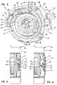
- FIG. 2 is a plan view of the preferred embodiment of the tension-relieving apparatus for the retractor assembly in the reference position;
- FIG. 2A is a plan view of the preferred embodiment of the tension-relieving apparatus for the retractor assembly in the activated position;
- FIG. 3 is a cross-sectional view of FIG. 2 along the line 3-3;
- FIG. 4 is a plan view of the tension-relieving apparatus of FIG. 2 in the tensionless mode;
- FIG. 5 is a side view of the tab and detent of FIG. 2 along line 5-5 in the reference position;
- FIG. 6 is a side view of the tab and detent disc of FIG. 5 in the activated position;
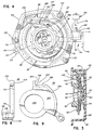
- FIG. 7 is an exploded view of the assembly of FIG. 2;
- FIG. 8 is a plan view of the unlocking disc of the tension-relieving apparatus;
- FIG. 9 is a side view of the unlocking disc in FIG. 8;
- FIG. 10 is a plan view of the lock control disc of the tension-relieving apparatus;
- FIG. 11 is a side view of the lock control disc of FIG. 10; and
- FIG. 12 is a diagrammatic illustration of a potential position of the remote automatic actuator of the present invention.
- The present invention broadly relates to a seat belt retractor system generally utilized in automobile safety systems. More particularly, the invention provides a retractor having a manually-engageable tensionless or tension-relieving mode in the retractor system. In FIG. 12, there is illustrated a typical seat system which is an automatic system for applying a lap belt and a shoulder belt to the occupant upon a closing of the door.
- As noted above, the present invention is directed to a
seat belt retractor 10, as shown in FIG. 1.Retractor 10 includes abelt 12 wound on awebbing reel 14 mounted onshaft 16, and a tensionless or tension-relieving means 18 mounted at oneend 20 ofshaft 16 for operation withreel 14. A rewind or biasing means orspring 22 is illustrated at the second orother end 23 ofshaft 16, whichspring 22 biases thereel 14 and belt 12 to the rewound position. Retractor assemblies for rewinding safety belts generally include anemergency locking mechanism 25, broadly shown in dashed outline, which may be of the inertia type operable by apendulum weight 27 mounted on a support bar to actuate and lock the retractor mechanism against belt protraction during a vehicle accident or other sudden deceleration. A locking mechanism is illustrated and discussed in U.S. Patent No. 4,361,294 at FIG. 1. - The tension-
relieving means 18 is manually operated into the tension-relieving state or mode by operation of an overtmanual actuator 62 which may be in the form of a button or lever positioned near the occupant to move a control cable 70 (FIGS. 2 and 7) or it may be in the form of a manually operated, electrical switch (not shown) to activate a solenoid plunger to move an actuator or to shift the tension-relieving means 18 from its non-activated state. Such systems often did not have a memory feature or a manual belt manipulation release, which could be activated by pulling the belt out beyond the memory distance. - In accordance with the present invention, the tension-relieving
means 18 may be actuated by operation of the overtmanual actuator 62, which shifts the tension-relievingmeans 18 to an activated or primed state (cf. FIG 2A); and thereafter a slight belt protraction, automatically shifts the tension-relievingmeans 18 into the tension-relieving position, as shown in FIG. 4, in whichnose 148 of tension-relievingpawl 58 engagesteeth 42 onratchet wheel 40, which is fixed byfingers 45 to reelshaft 16, to hold it against turning in the rewind direction (cf. arrow in FIG. 4) as urged by thereel spring 22. The tensionless means 18 has a memory position or state withpawl 58 held above theteeth 42 by acam surface 92 on first rotatable member or lockcontrol disc 50. So long asbelt 12 is not protracted beyond the memory distance,pawl 58 will be returned into engagement withratchet teeth 42 to reestablish the tension-relieving state. However, belt protraction beyond the memory distance causes tab means 98 to move into its detented or reference position (FIG. 5) to hold thelock control disc 50 with itscam surface 92 holdingpawl 58 from engagingratchet wheel 40, thus allowingbelt 12 to rewind onreel 14. If the occupant opens the vehicle door while the tension-relievingmeans 18 is in the tensionless state, theremote door actuator 64, usually a plunger or a switch in the doorway, shifts an actuator cable orplunger 79 to shift unlockingmember 38 tocam pawl 58 from engagement withteeth 42 on ratchet wheel 40 (cf. FIG. 2), which allowsbelt 12 to fully rewind when the occupant leaves the vehicle. - The preferred embodiment of the present invention is illustrated in cross-section in FIG. 3 and in FIG. 7 in an exploded view. As seen in these Figures, the tension-relieving
means 18 has a housing or cover 24, which housing or cover is generally cup-shaped with acavity 26 to receive the pawl and ratchet mechanism as well as the control discs.Housing 24 is illustrated as circular-shaped, as an example and not a limitation, withcover face 28 having a center location 30 (FIG. 4) and acentral post 32 extending frominner surface 36 ofcover 24 incavity 26.Post 32 is concentric with a surroundingannulus 34, which also extends frominner surface 36 ofcover 24 intocavity 26. Tensionless means 18 includes unlockingdisc 38, which is mounted and operable onannulus 34. Aratchet wheel 40, with a plurality ofratchet teeth 42 and indentations, has abore 44 to receivepost 32 for rotatable mounting thereon. When pawl 58 is engaged withratchet wheel 40, the ratchet wheel holdsreel shaft 16 to secure the belt in the tensionless mode against the rewinding bias force of biasing means 22. - A lock control disc or first
rotatable member 50 is mounted concentrically withratchet 40 and is biased for frictional engagement with a flange 41 ofratchet 40 by a disc spring orwasher 52 to maintain contact with the frictional surface ofratchet 40. An actuator means 54, to shift the lock control disc with operation of the manual overt actuator, includes an extendingarm 55, which is operable to engage or initiate the tensionless means 18 into the tensionless mode. Theassembly 18 is shifted into the tensionless mode by actuating the first external or overtmanual actuator 62 and is returned to its original release or detented position by a protraction ofbelt 12 beyond a predetermined distance. Manualovert actuator 62 has a bias means 62a, such as a spring, operable to returnactuator 62 andarm 55 to the reference position. A second remote or disengagingapparatus 64 is also operable to disengage the retractor assembly from the tension mode, whichremote disengaging apparatus 64 is generally operable by a vehicle door. That is, at door opening the door actuator ordisengagement apparatus 64 actuates an unlockingdisc 38 to disengage thepawl 58 from theratchet wheel 40 to establish the tensionless mode of FIG. 2, thereby allowingretractor assembly 10 to rewindbelt 12 at belt disengagement. - The following recitation will describe the noted tensionless means 18 in greater detail.
Tensionless apparatus 18 is illustrated in FIGS. 2-11 in both exploded and plan views. In FIG. 7, the actuator means 54 shifts thelock control disc 50 to activate the tensionless device. Actuator means 54 includes a manual actuator, which is preferably in the form of a lever or a push button, which is biased by a spring 62a, to return to its initial position after manual overt actuation by the occupant, to move acable 70 and thus acylindrical cam 71 projecting from the end of the cable at a right angle thereto and forming a T-shaped end, which is fitted into ahollow bore 69 in anactuator cam lug 66 fixed to one side of arotatable actuator pin 73. As best seen in FIG. 2, actuator pin is journaled to rotate about its longitudinal axis with one end ofpin 73 journaled in astationary member 75 fixed to cover 24, and the other end journaled in a bore in thecover 24. Thepin 73 is thus rotatable with a push or pull of thecable 70, which turns thepin 73 to cause itsinternal cam end 68, which is of semicircular cross-section, to turn from the detent position of FIG. 5. In the detent position,tab 98 on thelock control disc 50 is in aspace 76 between stationary detent shoulders 77 and 77a on thecover 24 and is movable to the activated position (FIG. 6) withtab 98 shifted to a position in which apointed end 99 on thetab 98 has been lifted or translated from thespace 76 and is positioned on a downward sloping surface of aramp 72. - As best seen in FIG. 5, turning of
actuator pin 73 counterclockwise causes its upper edge 73a to move against inclined cam surface 98a on thetab 98 and to push the latter down and to the left, as viewed in FIG. 5, thereby liftingtab 98 fromdetent gap 76. This movement oftab 98 rotatesdisc 50 slightly to the position of FIG. 6, wheretab point 99 is on the sloped surface of theup ramp 72, which positions lockcontrol disc 50 in its activated state for movement into its tensionless position. The actuator spring 62a shifts the cable to turn theactuator pin 73 back to its centered position of FIG. 5. A subsequent protraction of the belt will rotatecontrol disc 50 to move thetab point 99 further down the upramp 72 and to positionwindow 100 oncontrol disc 50 under thepawl stud 141. Manifestly, the actuator means 54 could include an electrical switch operated by the occupant to cause a solenoid or other electrical actuator to shift thetab 98 from the detented position of FIG. 5 to the activated position shown in FIG. 6. - Lock control disc or first
rotatable member 50 is illustrated in FIGS. 10 and 11 withfront surface 90, and acam control circumference 92 engageable withpawl stud 141, acentral bore 94, and aback surface 96.Disc 50 has thetab 98 which extends normally fromback surface 96, and a slot orwindow 100 alongcircumference 92, which may be an arc-shaped slot to allow thestud 141 to drop and thereby lower the pawl to engage the ratchet wheel. Anannular wall 102 extends fromfront surface 90 for frictional engagement and travel with a contact surface or flange 41 ofratchet 40. This frictional engagement comprises a friction clutch between the ratchet wheel and the lock control disc.Window 100, as further disclosed below, defines the limits of the tensionless mode per se. - Unlocking
disc 38, as illustrated in detail in FIGS. 8 and 9, has an annular shape with acircumference cam surface 108 to hold thepawl stud 141 up, and to lift the pawl from the ratchet to allow automatic belt rewind. The unlockingdisc 38 also has anouter surface 104, a central through-bore 106, and agroove 122 withshoulder 124,base 126 and ramp 128 sloped frombase 126 toouter edge 108. Unlockingdisc 38 is mounted incavity 26 ofhousing 24 withannulus 34 extending throughbore 106.Disc 38 has asidewall 109 cooperating withinner surface 112 to define apartial cavity 110. - The unlocking
disc 38 is shifted, for example, by adoor actuator mechanism 64, to rotate thecam surface 128 to cam upwardly thestud 141 which then rides on the camcircumferential surface 108, holding the pawl nose above the ratchet teeth, as shown in FIG. 2. The unlocking disc has alug 114, which pivots downwardly, as the disc is rotated counterclockwise by the door actuator. The preferred and illustrated door actuator includes a spring-biased door plunger, which is pushed inwardly by the door as it swings closed and which is pulled by a spring as the door opens in a conventional manner. This door plunger is connected by acable 79 to a T-end 81, which includes acylindrical pin 83 which is received in acylindrical bore 116 in thesecond lug 114 on the unlocking disc. Thesecond lug 114 projects fromsurface 112 generally normally thereto and has the through-bore 116 extending in the longitudinal direction with an intersecting blind-hole cross-bore 118 to receive the cable and intersecting bore 116.Second lug 114 is coupled to and operable with external disengaging means 64 by coupling means 79 (cf. FIGS. 2, 4 and 7), which means 64 may be the door plunger or which may be an electrical switch operable by an automobile door during its opening and closing to operate a solenoid (not shown) to rotate the unlocking disc.Slot 122 is operable to receive thestud 141 of securing means 58, to allow the pawl to lower to engage the ratchet. - Cover or
housing 24, as illustrated in FIG. 7, has annulus orannulus members 34 and post 32 extending frominner surface 36.Cover 24 is generally cup-shaped and includes a plurality of mountinglugs 132 and a projecting mounting post orstud 134.Sidewall 136 cooperates withinner surface 36 to definecavity 26, which is generally operable to receive the assembly comprising tensionless or tension-relievingmeans 18. The upramp 72 and thedown ramp 74 are formed on the cover inner surface and project toward the ratchet wheel. Thedetent space 76 is located betweenshoulders 77 and 77a on theramps - Securing means 58 in FIG. 7 is a pawl for engagement with
ratchet teeth 42 or engagement in ratchet grooves ofratchet 40.Pawl 58 is shown as having a dogleg shape with a through-bore 130 at one end to receive mountingpost 134, andpawl 58 is pivotable or rotatable thereon.Stud 141 extends generally normally fromrear face 142 ofpawl 58.Pawl 58 includes abead 143 for maintainingpawl 58 in its pivotable position inretractor assembly 10. - As illustrated in FIG. 3, the assembly has
ratchet 40 withhub 39, which is seated withinannulus 34. As noted above, ratchet 40 includes acentral hub 39 about which are a plurality ofteeth 42 engageable withpawl 58, which pawl 58 will restrain rewinding action ofreel 14 by retention of theratchet 40. In the assembly,disc spring 52 is mounted againstannulus 34 and abouthub 39 to bias thelock control disc 50 against thefriction surface 43 of ratchet flange 41. Therefore,lock control disc 50 is normally biased to move and rotate withratchet 40, which ratchet is mounted onshaft 16 withfingers 45 and rotatable withshaft 16. As the vehicle door closes,remote door actuator 64 moves lug 114 through connectingmeans 79 to rotate automatically-operable actuator or unlockingdisc 38 into the position noted in FIG. 4 withgroove 122 in position to receivestud 141 ofpawl 58 whenwindow 100 ofdisc 50 is aligned therewith. Initially, when the occupant buckles himself in with the seat buckle on his shoulder, the tensionless device is inoperative and in its release state, with belt tension on the shoulder of the occupant. In this initial position, the lock control disc is detented with tab means 98 in thedetent space 76 betweenramps tab 98 is constrained between the ramp shoulders 77 and 77a, and thepawl 58 is raised withstud 141 on thecam surface 92 holding the pawl above theratchet teeth 42 to maintainbelt 12 in a tensioned state. - The tensionless mode may be initiated by depression or actuation of manual
overt actuator 62 to turnpin 73 to move thetab 98 and thelock control disc 50 axially inwardly toward theratchet wheel 40 and to turn lock control disc clockwise to the activated position shown in FIG. 2A. That is, the activated state or mode is attained by the actuation ofmanual actuator 62 to rotatelug 66,arm 55 and end 68 to displacetab 98 fromdetent space 76 withtab point 99 on slopedsurface 72, as seen in FIG. 6. Thereafter, protraction of the belt turns the reel and the ratchet, and frictional engagement oflock control disc 50 withratchet 40moves window 100 on the lock control disc into alignment withgroove 122 beneath thestud 141, thepawl 58 rotates down and positions thestud 141. At alignment ofwindow 100 andgroove 122,pawl 58 withstud 141, which is rotatable on mountingmeans 134, is nested in the alignedgroove 122 andwindow 100.Pawl 58 engagesratchet 40 to inhibit retraction ofbelt 12, which is biased byspring 22 to rewindreel 14, thus attaining the tensionless state, as illustrated in FIG. 4. Subsequent protraction ofbelt 12 in the tensionless state will rotatelock control disc 50, which is biased byspring 22 in the rewinding direction, to movepawl stud 141 alonglower surface 101 and upramp 105 tocircumference cam surface 92 to lift thepawl 58, and thereby be in the "memory" state. If belt protraction is less than the predetermined "memory" range of thecam surface 92, as the occupant leans back to allow belt rewind,lock control disc 50 will rotate in the rewinding direction to reengage the tensionless mode whenwindow 100 and groove 122 are aligned to receivepawl stud 141 and to allow pawl end 148 to drop into engagement with one ofratchet teeth 42. Protraction beyond the predetermined memory range will rotate the lock control disc through a distance to cause thepoint 99 on thetab 98 to slide along the down ramp until the point slides off at shoulder 77a and moves toward the cover to again nest indetent space 76 and thereby resetting the tensionless device in its original tensioned and detented state. - As shown in FIG. 4, the tensionless state is defined by aligning the
stud 141 with thegroove 122 andwindow 100 to allow engagement ofpawl end 148 withratchet teeth 42. When in tensionless mode, abelt 12 protraction which rotates thetab 98 less than the distance to reenterdetent 76 with thecam surface 92 holding thestud 141 and pawl upwardly, allows the spring bias to act to rewindbelt 12 and repositionwindow 100 in alignment withgroove 122 to permitstud 141 to again nest therein forpawl 58 engagement withratchet 40, thus reestablishing the tensionless mode. - In FIGS. 2, 4 and 7, first
rotatable member 50 has a generally circular shape with the arc-shapedwindow 100 at itscircumference 92. When thedisc 50 is rotated in the clockwise direction from the tensionless position,inclined cam surface 105cams stud 141 upwardly to thecircumference cam surface 92. With the vehicle door closed, groove 122 on the unlocking disc is aligned for receipt ofpawl stud 141 and when the unlockingdisc 38 is rotated by theautomatic operator 64, theinclined cam surface 128 of unlockingmember 38lifts stud 141 ontocam surface 108, and thereby the pawl from the ratchet, to cause automatic belt rewind. As noted above, the tensionless mode per se is defined wherewindow 100 is in alignment withgroove 122 of automatically operable a actuator or unlockingdisc 38, which alignment can receivepawl stud 141 forpawl end 148 engagement withratchet teeth 42 for securingreel 14 from rewindingbelt 12. -
Belt 12 includes a "memory" in the tensionless mode. That is, withpawl stud 141 nested inwindow 100 andgroove 122, thebelt 12 may be protracted a short distance, such as less than three to four inches, and thereafter returned to the tensionless setting. The memory position is achieved by protraction ofbelt 12, as seen in FIGS. 2, 4 and 7, in a clockwise rotation ofratchet 40 and firstrotational member 50. This rotary motion of firstrotational member 50 movespawl stud 141 alonglower surface 101 andinclined surface 105 ofwindow 100, to ride along thecircumference cam surface 92. This upward travel of thestud 141 lifts and disengages pawl 58 fromratchet teeth 42 and enables bias means 22 to again apply a biasing or tensioning force to reel 14 andbelt 12. Restoration of the tensionless mode is accomplished when the occupant leans back and thecam surface 92 travels along under thepawl stud 141 until thelower surface 101 comes under the stud, which then is lowered intowindow 100. That is, for belt protraction less than the predetermined distance,pawl stud 141 continues to ridecam circumference 92 ondisc 50, as biased byspring 22, as the latter turns counterclockwise to return to the tensionless setting in which thewindow 100 aligns withgroove 122 andstud 141 drops therein. Thus, travel ofpawl stud 141 oncam circumference 92 without repositioningtab 98 in thedetent 76 will operate as the "memory" or memory distance. As noted above, travel beyond the predetermined distance will repositiontab 98 in thedetent 76 with thecam surface 92 positioned to lift thestud 141 and thereby holdpawl 58 disengaged fromratchet 40. - At occupant egress from the vehicle with
belt 12 and tension-relievingmeans 18 in the tensionless position, an opening of the door actuatesdoor actuator 64 to move connectingmeans 79, which is coupled to lug 114, to rotate the automatically-operable unlockingdisc 38 aboutannulus 34. Rotation ofdisc 38 in a clockwise direction from the position shown in FIG. 4 will move upwardly-slopedramp 128 to engage and to liftpawl stud 141 with thepawl 58 pivoting aboutpivot stud 134.Pawl 58 is lifted and disengaged fromratchet 40, which allows bias means 22 to urgereel 14 to rewindbelt 12, and thebelt 12 will again be at its tensioned state. If the belt is stretched as shown in FIG. 12 when the door is open, the tension is on the belt to rewind the belt onto the reel as the door is closed. During this rewind,lock control disc 50, which is biased for frictional engagement withratchet 40, will rotate withratchet 40 during the belt rewinding to travel up theramp 72 and then drop into thedetent space 76, whereby the shoulder 77a holds thetab 98 against further counterclockwise rotation. With thecontrol disc 50 detented, thecam surface 92 is holdingpawl nose 148 from the ratchet wheel and thewindow 100 on the control disc will not be beneath thepawl stud 141. Closure of the vehicle door will rotate the unlockingdisc 38 to position itsgroove 122 beneath thepawl stud 141, but thecam surface 92 on thedisc 50 still holds the pawl from the ratchet wheel. In order to reestablish the tensionless state, the occupant must make the conscious act of actuating the manualovert actuator 62 and thereafter protract the belt, which protraction rotates thedisc 50 to bring thewindow 100 beneath thepawl stud 141, allowing the pawl to drop to engage the ratchet and thereby establish the tensionless mode. - From the foregoing, it will be seen that the tensionless device may be belt-manipulated into a tensionless state only after an overt, deliberate manual actuation followed by a belt protraction by the occupant. Thereafter, belt manipulations will either have caused a memory position, or a movement to a release position or state to cause belt rewind.
- While only specific embodiments of the invention have been described and shown, it is apparent that various alterations and modifications can be made therein. It is, therefore, the intention in the appended claims to cover all such modifications and alterations as may fall within the scope of the invention as defined in the appended claims.
Claims (4)
- A seat belt retractor for rewinding a seat belt, said retractor (10) comprising:
a reel (14);
a first biasing means (22) for biasing the reel (14) to retract and to rewind the belt (12) on the reel (14);
an emergency locking means (25) for locking the belt (12) against protraction at the time of an accident;
a tension-relieving means (18) for relieving a tension force positionable in a tension-relieving position applied by the belt onto an occupant body in a vehicle by blocking belt retraction and rewinding movement of the reel and positionable in a release position in which the tension-relieving means (18) is inoperable from relieving belt tension;
the tension-relieving means (18) including a pawl (58) and a ratchet means (40) which is connected to the reel (14) and rotatable therewith until the pawl (58) is in blocking engagement with the ratchet means (40) to restrain rewinding of said belt;
a manual overt actuator (62) for shifting the tension-relieving means (18) to an activated position from which said tension-relieving means (18) may be shifted to the tensionless position by belt protraction;
means (92, 99) operable by belt protraction beyond a predetermined distance to shift the pawl (58) from blocking engagement with the ratchet means (40) at its tension-relieving position to its release position allowing the biasing means to rewind the belt (12) onto the reel (14);
a detent means (98, 76) to detent the tension-relieving means (18) in the release position allowing belt rewind by the biasing means (22); and
a first rotatable member (50) operable to shift from a detented position in which the first rotatable member (50) is detented by the detent means (98, 76) to the activated position where said first rotatable member (50) is movable from said activated position by a subsequent belt protraction to allow the pawl (58) to move into blocking engagement with the ratchet means (40);
characterised in that the first rotatable member (50) comprises a disc having a tab means (98) cooperating with detent means (76, 77, 77a) for detenting the disc at the release position until the manual actuator (62) shifts the tab means (98) from the detent means (76, 77, 77a) and shifts the rotatable member (50) to the activated position, the disc and the ratchet means (40) being frictionally engaged and the ratchet means (40) turning the disc from the activated position to the tension-relieving position upon a subsequent protraction of the belt (12). - A seat belt retractor as claimed in claim 1, wherein a housing (24) defines an enclosure for said tension-relieving means (18), and said detent means (76, 77, 77a) is mounted on said housing and has a detenting engagement with the tab means (98) to hold said first rotatable member (50) at said release position until said tab means (98) and first rotatable member (50) are shifted by said manual overt actuator (62) to said activated position.
- A seat belt retractor as claimed in claim 2 wherein said housing (24) has an inner surface;
said detent means (76, 77, 77a) has a first ramp (72) with a first sloped surface and a second ramp (74) with a second sloped surface, said first and second ramps (72, 74) are mounted on said housing inner surface and cooperate to define the detent means therebetween;
cam means (68) operable by said manual overt actuator (62) to shift the tab means (98) from the detent means (76, 77, 77a);
said tab means (98) is positioned in said detent means (76, 77, 77a) at said release position, which tab means (98) is movable from said detent means (76, 77, 77a) to said activated position by actuation of said manual overt actuator (62) and said cam means (68). - A seat belt retractor as claimed in claim 3, wherein said retractor further comprises a shaft (16) biased by said first biasing means (22);
said reel (14) is mounted on said shaft;
said ratchet means (40) is fixedly connected to said shaft;
said rotatable member (50) having a cam surface (92) and a window (100) in said cam surface; and,
said pawl (50) having a pawl (141) stud which nests in said window to allow the pawl to engage said ratchet means to establish the tensionless mode.
Applications Claiming Priority (3)
| Application Number | Priority Date | Filing Date | Title |
|---|---|---|---|
| US07/336,100 US4976474A (en) | 1988-03-31 | 1989-04-11 | Selective active overt comfort system |
| PCT/US1990/001973 WO1990011915A1 (en) | 1989-04-11 | 1990-04-11 | Selective active overt comfort system |
| US336100 | 2003-01-03 |
Publications (3)
| Publication Number | Publication Date |
|---|---|
| EP0466821A1 EP0466821A1 (en) | 1992-01-22 |
| EP0466821A4 EP0466821A4 (en) | 1993-05-19 |
| EP0466821B1 true EP0466821B1 (en) | 1996-10-02 |
Family
ID=23314569
Family Applications (1)
| Application Number | Title | Priority Date | Filing Date |
|---|---|---|---|
| EP90906613A Expired - Lifetime EP0466821B1 (en) | 1989-04-11 | 1990-04-11 | Selective active overt comfort system |
Country Status (7)
| Country | Link |
|---|---|
| US (1) | US4976474A (en) |
| EP (1) | EP0466821B1 (en) |
| JP (1) | JPH04504394A (en) |
| KR (1) | KR920700965A (en) |
| CA (1) | CA2049345A1 (en) |
| DE (1) | DE69028773D1 (en) |
| WO (1) | WO1990011915A1 (en) |
Families Citing this family (4)
| Publication number | Priority date | Publication date | Assignee | Title |
|---|---|---|---|---|
| JP2526348B2 (en) * | 1992-05-27 | 1996-08-21 | タカタ株式会社 | Rotator actuator actuation pretensioner |
| US5520350A (en) * | 1994-02-22 | 1996-05-28 | Takata Inc. | Seat belt retractor having an intentional set comfort system |
| DE19856364A1 (en) * | 1998-12-07 | 2000-06-08 | Trw Repa Gmbh | Belt retractor for a vehicle seat belt |
| US20250043605A1 (en) * | 2023-07-31 | 2025-02-06 | GM Global Technology Operations LLC | Cable-less end gate for a vehicle |
Family Cites Families (20)
| Publication number | Priority date | Publication date | Assignee | Title |
|---|---|---|---|---|
| US3682412A (en) * | 1969-09-22 | 1972-08-08 | American Safety Equip | Safety restraint system retraction device |
| US3700184A (en) * | 1971-02-08 | 1972-10-24 | Ford Motor Co | Seat belt retraction disabling device |
| GB1366190A (en) * | 1971-11-09 | 1974-09-11 | Rainsfords Met Prod | Seat belt take-up spool latch |
| US3869098A (en) * | 1973-08-23 | 1975-03-04 | Gen Motors Corp | Vehicle occupant restraint belt retractor |
| US3851836A (en) * | 1973-08-23 | 1974-12-03 | Gen Motors Corp | Vehicle occupant restraint belt retractor |
| US4023746A (en) * | 1975-06-16 | 1977-05-17 | General Motors Corporation | Belt retractor with winding prevention and memory mechanism |
| US4106722A (en) * | 1976-03-26 | 1978-08-15 | K. K. Tokai Rika Denki Seisakusho | Device for preventing excessive tightness of seatbelts |
| US4053116A (en) * | 1976-05-21 | 1977-10-11 | Takata Kojyo Co., Ltd. | Retraction locking safety belt retractor |
| US4065072A (en) * | 1976-07-30 | 1977-12-27 | General Motors Corporation | Seat belt retractor with winding prevention mechanism |
| US4124175A (en) * | 1977-06-10 | 1978-11-07 | Gateway Industries, Inc. | Retractor with tension relieving mechanism |
| US4293107A (en) * | 1979-08-23 | 1981-10-06 | American Safety Equipment Corporation | Tension relieving selective engagement mechanism with memory |
| US4386745A (en) * | 1981-08-10 | 1983-06-07 | General Motors Corporation | Tension reliever for seat belt retractor |
| US4458920A (en) * | 1981-11-10 | 1984-07-10 | Fuji Kiko Kabushiki Kaisha | Tensionless seat belt retractor |
| JPS58198357A (en) * | 1982-02-24 | 1983-11-18 | レパ・フアインシユタンツヴエルク・ゲゼルシヤフト・ミツト・ベシユレンクテル・ハフツング | Apparatus for winding up safety belt of automobile |
| DE3206596C2 (en) * | 1982-02-24 | 1986-02-06 | TRW Repa GmbH, 7071 Alfdorf | Device for strain relief in retractors for seat belts in motor vehicles |
| US4585185A (en) * | 1982-10-22 | 1986-04-29 | Nsk-Warner K.K. | Retractor |
| US4506845A (en) * | 1983-02-09 | 1985-03-26 | Nsk-Warner K.K. | Tension locking mechanism of a retractor |
| US4603877A (en) * | 1985-04-15 | 1986-08-05 | General Motors Corporation | Control means for occupant restraint belt system |
| US4669751A (en) * | 1986-01-24 | 1987-06-02 | American Safety Equipment Corporation | Tension eliminator for a vehicle safety belt retractor |
| US4854522A (en) * | 1988-04-04 | 1989-08-08 | Trw Vehicle Safety Systems Inc. | Safety apparatus |
-
1989
- 1989-04-11 US US07/336,100 patent/US4976474A/en not_active Expired - Lifetime
-
1990
- 1990-04-11 WO PCT/US1990/001973 patent/WO1990011915A1/en not_active Ceased
- 1990-04-11 CA CA002049345A patent/CA2049345A1/en not_active Abandoned
- 1990-04-11 DE DE69028773T patent/DE69028773D1/en not_active Expired - Lifetime
- 1990-04-11 EP EP90906613A patent/EP0466821B1/en not_active Expired - Lifetime
- 1990-04-11 KR KR1019910701295A patent/KR920700965A/en not_active Ceased
- 1990-04-11 JP JP2506258A patent/JPH04504394A/en active Pending
Also Published As
| Publication number | Publication date |
|---|---|
| KR920700965A (en) | 1992-08-10 |
| WO1990011915A1 (en) | 1990-10-18 |
| DE69028773D1 (en) | 1996-11-07 |
| US4976474A (en) | 1990-12-11 |
| EP0466821A4 (en) | 1993-05-19 |
| EP0466821A1 (en) | 1992-01-22 |
| JPH04504394A (en) | 1992-08-06 |
| CA2049345A1 (en) | 1990-10-12 |
Similar Documents
| Publication | Publication Date | Title |
|---|---|---|
| US4310128A (en) | Seat belt retracting and winding device | |
| US4566649A (en) | Conversion control for combination VSI and ALR retractor | |
| US4592520A (en) | Webbing tension device | |
| CA1054122A (en) | Belt retractor with winding prevention mechanism | |
| WO1988004245A1 (en) | Seat belt retractor | |
| US5265823A (en) | Tension relieving mechanism for a safety belt system | |
| US4384735A (en) | Safety restraint system having tensionless type belt retractor adapted for adjustable seat | |
| US4993657A (en) | Dual spring retractor | |
| US4065072A (en) | Seat belt retractor with winding prevention mechanism | |
| US4854522A (en) | Safety apparatus | |
| US4552319A (en) | Combination VSI and ALR retractor | |
| US5520350A (en) | Seat belt retractor having an intentional set comfort system | |
| US4919450A (en) | Overt comfort system | |
| US4307853A (en) | Rewind prevention for dual spool retractors | |
| US4976474A (en) | Selective active overt comfort system | |
| US4344588A (en) | Seat belt retractor assembly with post emergency spool release | |
| US4149683A (en) | Safety belt tension eliminator with webbing sensitive release | |
| US4361294A (en) | Tension relieving mechanism | |
| GB1560604A (en) | Dual tension safety belt | |
| US4164335A (en) | Automatic locking retractor with lock-up delay | |
| US4343445A (en) | Dual spool seat belt retractor with comfort feature | |
| US4346858A (en) | External release for reduced tension mechanism | |
| US4320878A (en) | Vehicle occupant restraint belt retractor | |
| US4367851A (en) | Seat belt retractor with a tension eliminator | |
| US4717089A (en) | Webbing retractor for vehicle |
Legal Events
| Date | Code | Title | Description |
|---|---|---|---|
| PUAI | Public reference made under article 153(3) epc to a published international application that has entered the european phase |
Free format text: ORIGINAL CODE: 0009012 |
|
| 17P | Request for examination filed |
Effective date: 19911005 |
|
| AK | Designated contracting states |
Kind code of ref document: A1 Designated state(s): DE FR GB IT SE |
|
| A4 | Supplementary search report drawn up and despatched |
Effective date: 19930330 |
|
| AK | Designated contracting states |
Kind code of ref document: A4 Designated state(s): DE FR GB IT SE |
|
| 17Q | First examination report despatched |
Effective date: 19950623 |
|
| GRAG | Despatch of communication of intention to grant |
Free format text: ORIGINAL CODE: EPIDOS AGRA |
|
| GRAH | Despatch of communication of intention to grant a patent |
Free format text: ORIGINAL CODE: EPIDOS IGRA |
|
| GRAH | Despatch of communication of intention to grant a patent |
Free format text: ORIGINAL CODE: EPIDOS IGRA |
|
| GRAA | (expected) grant |
Free format text: ORIGINAL CODE: 0009210 |
|
| AK | Designated contracting states |
Kind code of ref document: B1 Designated state(s): DE FR GB IT SE |
|
| PG25 | Lapsed in a contracting state [announced via postgrant information from national office to epo] |
Ref country code: FR Effective date: 19961002 Ref country code: IT Free format text: LAPSE BECAUSE OF FAILURE TO SUBMIT A TRANSLATION OF THE DESCRIPTION OR TO PAY THE FEE WITHIN THE PRE;WARNING: LAPSES OF ITALIAN PATENTS WITH EFFECTIVE DATE BEFORE 2007 MAY HAVE OCCURRED AT ANY TIME BEFORE 2007. THE CORRECT EFFECTIVE DATE MAY BE DIFFERENT FROM THE ONE RECORDED.SCRIBED TIME-LIMIT Effective date: 19961002 |
|
| REF | Corresponds to: |
Ref document number: 69028773 Country of ref document: DE Date of ref document: 19961107 |
|
| PG25 | Lapsed in a contracting state [announced via postgrant information from national office to epo] |
Ref country code: SE Effective date: 19970102 |
|
| PG25 | Lapsed in a contracting state [announced via postgrant information from national office to epo] |
Ref country code: DE Effective date: 19970103 |
|
| EN | Fr: translation not filed | ||
| PG25 | Lapsed in a contracting state [announced via postgrant information from national office to epo] |
Ref country code: GB Effective date: 19970411 |
|
| PLBE | No opposition filed within time limit |
Free format text: ORIGINAL CODE: 0009261 |
|
| STAA | Information on the status of an ep patent application or granted ep patent |
Free format text: STATUS: NO OPPOSITION FILED WITHIN TIME LIMIT |
|
| 26N | No opposition filed | ||
| GBPC | Gb: european patent ceased through non-payment of renewal fee |
Effective date: 19970411 |