EP0466369B1 - Scanning apparatus and method - Google Patents
Scanning apparatus and method Download PDFInfo
- Publication number
- EP0466369B1 EP0466369B1 EP91305853A EP91305853A EP0466369B1 EP 0466369 B1 EP0466369 B1 EP 0466369B1 EP 91305853 A EP91305853 A EP 91305853A EP 91305853 A EP91305853 A EP 91305853A EP 0466369 B1 EP0466369 B1 EP 0466369B1
- Authority
- EP
- European Patent Office
- Prior art keywords
- helical
- medium
- light beam
- scanning apparatus
- helicoid
- Prior art date
- Legal status (The legal status is an assumption and is not a legal conclusion. Google has not performed a legal analysis and makes no representation as to the accuracy of the status listed.)
- Expired - Lifetime
Links
- 238000000034 method Methods 0.000 title claims description 14
- 230000003287 optical effect Effects 0.000 claims abstract description 85
- 238000007493 shaping process Methods 0.000 claims description 8
- 230000004075 alteration Effects 0.000 description 5
- 239000000463 material Substances 0.000 description 5
- 238000007516 diamond turning Methods 0.000 description 3
- XAGFODPZIPBFFR-UHFFFAOYSA-N aluminium Chemical compound [Al] XAGFODPZIPBFFR-UHFFFAOYSA-N 0.000 description 2
- 229910052782 aluminium Inorganic materials 0.000 description 2
- 238000013459 approach Methods 0.000 description 2
- 238000010276 construction Methods 0.000 description 2
- 239000011159 matrix material Substances 0.000 description 2
- 230000004323 axial length Effects 0.000 description 1
- 230000001419 dependent effect Effects 0.000 description 1
- 238000003754 machining Methods 0.000 description 1
- 238000004519 manufacturing process Methods 0.000 description 1
- 238000010137 moulding (plastic) Methods 0.000 description 1
- 230000010363 phase shift Effects 0.000 description 1
- 238000005498 polishing Methods 0.000 description 1
- 230000008569 process Effects 0.000 description 1
- 230000009467 reduction Effects 0.000 description 1
- 230000001360 synchronised effect Effects 0.000 description 1
Images


Classifications
-
- H—ELECTRICITY
- H04—ELECTRIC COMMUNICATION TECHNIQUE
- H04N—PICTORIAL COMMUNICATION, e.g. TELEVISION
- H04N1/00—Scanning, transmission or reproduction of documents or the like, e.g. facsimile transmission; Details thereof
- H04N1/04—Scanning arrangements, i.e. arrangements for the displacement of active reading or reproducing elements relative to the original or reproducing medium, or vice versa
- H04N1/12—Scanning arrangements, i.e. arrangements for the displacement of active reading or reproducing elements relative to the original or reproducing medium, or vice versa using the sheet-feed movement or the medium-advance or the drum-rotation movement as the slow scanning component, e.g. arrangements for the main-scanning
- H04N1/16—Scanning arrangements, i.e. arrangements for the displacement of active reading or reproducing elements relative to the original or reproducing medium, or vice versa using the sheet-feed movement or the medium-advance or the drum-rotation movement as the slow scanning component, e.g. arrangements for the main-scanning using a rotating helical element
-
- G—PHYSICS
- G02—OPTICS
- G02B—OPTICAL ELEMENTS, SYSTEMS OR APPARATUS
- G02B26/00—Optical devices or arrangements for the control of light using movable or deformable optical elements
- G02B26/08—Optical devices or arrangements for the control of light using movable or deformable optical elements for controlling the direction of light
- G02B26/10—Scanning systems
Definitions
- the present invention relates to line scanners generally and to helical line scanners in particular where, for the purposes of this application, scanning refers to both a reading and a writing capability.
- the helicoid reflector has advantages over existing scanners. As discussed in the article by Leo Beiser, "Generalized Equations for the Resolution of Laser Scanners", Applied Optics , 15 October 1983, Vol. 22, No. 20, pp. 3149 - 3150, existing scanners use rotating pyramidal or polygonal mirrors inherently have format and resolution limitations. The helicoid reflectors have none of these limitations.
- a single helicoid reflector is less prone to production errors thereby providing a scan without noticeable artifacts.
- a flat helical surface cannot be completely flat. In fact, it inherently has a shape defined by a saddle function. Thus, a collimated light beam reflecting from such a surface becomes diverged.
- the optical scanning device of U.S. Patent 3,523,160 uses a lens after the helical surface to refocus the beam.
- the optical scanning device of U.S. Patent 4,494,821 improves on the device of U.S. Patent 3,523,160 so as to reduce the divergence of the light beam through the introduction of a narrow slit.
- the narrow slit is not advantageous since it produces a relatively large spot in the shape of a parallelogram.
- US-A-4066328 discloses scanning apparatus in which light is projected as a beam from a fixed laser source onto a helical reflecting surface continuously rotating about its central axis.
- the beam impinges the reflecting surface in an incident direction substantially parallel to the rotation axis and is reflected from the surface in a direction skew to this axis.
- a reflector extending the full axial length of the reflecting surface then reflects the beam back onto the reflecting surface in a direction so oriented that the reflecting surface reflects the beam a second time, but now in a direction generally perpendicular to the axis of rotation.
- the reflecting surface and the reflector are both concave so as to condense the beam.
- a reflecting surface tilted to the axis of helix is desired. This angle is called the pitch angle.
- scanning apparatus comprising: a light source for providing at least one light beam; a medium for receiving said at least one light beam; and first helical optical means disposed between said light source and said medium; characterised by second helical optical means disposed between said first helical optical means and said medium, said first helical optical means receiving said at least one light beam and directing it to said second helical optical means which directs said at least one light beam towards said medium; and means for rotating said first and second helical optical elements in an identical direction or in an opposite direction.
- said first and second helical optical means have first and second specularly reflecting helical surfaces respectively, said first helical surface being operative for receiving said at least one light beam from said light source and for directing it to said second helical surface and said second helical surface being operative for receiving said at least one light beam from said first helical surface and for directing it to said medium.
- the first and second helical surfaces can have diameters of different sizes or can be of a generally identical size. Furthermore, the first helical surface preferably completes one turn per scan.
- the specularly reflecting surfaces are flat.
- each of the specularly reflecting surfaces can have a constant radius of curvature or a curvature defined by a higher than second order curve.
- the first and second helical optical apparatus include two specularly reflecting helical surfaces combined in a single helicoid optical element.
- the apparatus of this embodiment can additionally include a prism or two mirrors.
- said first helical optical means comprises a helicoid optical element housed within a cylindrical lens twisted to form a helix.
- the medium may be transparent and the apparatus may include a detector located near the medium for detecting light through the medium.
- the medium may be non-transparent and the apparatus may include a detector located near the medium for detecting light reflecting from the medium.
- a method of scanning a medium including the steps of: providing at least one light beam; receiving said at least one light beam on a first helical optical means and reflecting and shaping it to said medium; characterised by receiving said at least one light beam from said first helical optical means on a second helical optical means and reflecting and shaping it to said medium; and repeating said step of providing and both steps of receiving while rotating said first and second helical optical means in an identical direction or in opposite directions.
- the scanning apparatus of the present invention comprises a light source 10, such as a laser, for providing a light beam 11 which is generally but not necessarily collimated and two helicoid optical elements 12 and 14 having specularly reflecting helical surfaces 16 and 18, respectively, for receiving the light beam 11 and for reflecting it onto a medium 20.
- a light source 10 such as a laser
- two helicoid optical elements 12 and 14 having specularly reflecting helical surfaces 16 and 18, respectively, for receiving the light beam 11 and for reflecting it onto a medium 20.
- light source 10 can comprise a multiplicity of light sources which provide a multiplicity of light beams with slight angles between them.
- the following detailed description will discuss the operation of the apparatus of the present invention utilizing a single light beam 11, it being understood that light beam 11 can be replaced by a multiplicity of light beams without any loss of generality.
- Light beam 11 is transmitted along an axis which is preferably parallel to axes of symmetry 13 and 15 of helicoid optical elements 12 and 14, respectively, which, in turn, are preferably parallel one to the other. If light beam 11 is replaced by a multiplicity of light beams, the central axis of the light beams is parallel to axes 13 and 15.
- the axis of light beam 11 and the axes 13 and 15 are not coplanar; the axis of light beam 11 typically is at an angle ⁇ to a line 29 between axes 13 and 15.
- the angle ⁇ is known as the working point of the light beam 11 on the helical surface 16.
- Light beam 11 impinges upon helical surface 16 and is reflected from there, as beam 22, onto helical surface 18.
- Helical surface 18 then reflects beam 22, as beam 24, onto the medium 20.
- Beam 24 is scanned along a line on medium 20 through the rotation of helicoid optical elements 12 and 14 in an identical direction, marked by arrows 26. It will be noted that any direction of rotation is possible so long as both elements 12 and 14 rotate in that direction.
- medium 20 is translated a distance of one line width generally perpendicular to the scan direction via translating means (not shown) known in the art, such as lead screws, linear motors and rotating drums.
- translating means such as lead screws, linear motors and rotating drums.
- medium 20 is translated a distance of a number of line widths equal to the number of light sources.
- medium 20 can be fixed and the scanning apparatus comprising the two helicoid optical elements 12 and 14 can be translated as required.
- medium 20 is not necessarily flat; it merely has to have the scanned line maintained at a constant distance from the scanning apparatus.
- Helicoid optical elements 12 and 14 are rotated and synchronized through well known rotating means 25, such as geared motors or motors with closed servo loops.
- helical surface 16 In order to scan a single line or several lines in the case of a multiplicity of light sources, helical surface 16 is restricted to forming a single turn of a helix, or, if necessary, slightly less than a single turn, over a length L of helicoid optical element 12.
- Helical surface 18, on the other hand can be formed of a single helix over length L with a multiplicity M of turns, wherein M is an integral multiple of the portion of a turn of helical surface 16. Accordingly, the angular velocity of helicoid optical element 14 is M times the angular velocity of helicoid optical element 12. It will be noted that, although not shown in Fig. 1A, the second helicoid optical element 14 can be of any length which is greater than or equal to length L.
- Helical surfaces 16 and 18 have pitch angles ⁇ 1 and ⁇ 2 which are defined such that, at the point of reflection, the reflecting surfaces are generally orthogonal to each other. This partially compensates for aberrations in beam 22 caused by the fact that the surface 16 by its nature is not flat. This is illustrated in more detail in Fig. 1B which is a sectional view showing projections 17 and 19 of the helical surfaces 16 and 18, respectively, along the axis of light beam 22. An angle ⁇ , the angle between projection 17 and 19, is arranged to be as large as possible where 90° is its maximal value.
- helical surfaces 16 and 18 are phase shifted from each other.
- the size of the phase shift is defined by the condition that beam 22 hit helical surface 18 and depends upon the geometry of the helical surfaces 16 and 18 and a distance S3 between the axes 13 and 15.
- the length L and pitch angle ⁇ 1 of helical surface 16 define its diameter D1.
- the pitch angle ⁇ 2 of the helical surface 18 is defined.
- each helical surface 16 or 18 is typically inclined by an inclination angle ⁇ i to the extension 30 of a radial line of its respective helicoid optical element 14 or 16, where i is 1 or 2.
- ⁇ 1 is the inclination angle of helical surface 16
- ⁇ 2 is the inclination angle of helical surface 18.
- ⁇ 1 and ⁇ 2 are defined, for convenience, in a plane which is perpendicular to the axes 13 and 15. They may be unequal.
- helical surfaces 16 and 18 can be concave so as to focus light beam 11 or 22, respectively.
- Helical surfaces 16 and 18 can have fixed radii of curvature R i , as shown in Fig. 2B, or the curvature can be a higher than second order curve.
- the inclination angles ⁇ i in this embodiment are defined as the angle between a tangent 31 to the concave surface 16 or 18 at its middle and the extension 30.
- FIG. 3A illustrates, in detail, the path of an input light beam, marked 40, as it reflects from helical surfaces 16 and 18 with flat surfaces such as are shown in Fig. 2A.
- the helical surfaces 16 and 18 are marked as surfaces 42 and 44, respectively.
- Fig. 3B illustrates the cross-section of light beam 40 before it reflects from helical surface 42. It will be noted that the cross-section is generally round.
- Light beam 40 reflects from surface 42 as light beam 46 whose cross-section is shown in Fig. 3C. Since, as mentioned hereinabove, helical surface 42 is a saddle shape, it causes divergence in any beam which it reflects. Thus the cross-section of light beam 46 has a shape of a diverged ellipse.
- the divergence shown in Fig. 3C is generally cancelled when light beam 46 is reflected from helical surface 44 as a light beam 48 which impinges upon the medium 20.
- Helical surface 44 causes a divergence of light beam 46 in a perpendicular direction to the divergence caused by helical surface 42; thus, the resultant cross-section, shown in Fig. 3D, is a nearly collimated beam 48 whose diameter is larger than that of beam 40.
- FIG. 4A-4D The path and shape of an input light beam, marked 50, as it reflects from helical surfaces 16 and 18 with curved concave surfaces such as described with reference to Fig. 2B, is shown in Figs. 4A-4D in a manner similar to that for the generally flat surfaces of Fig. 2A.
- the helical surfaces 16 and 18 are marked as surfaces 52 and 54, respectively.
- Fig. 4B illustrates the cross-section of light beam 50 before it reflects from helical surface 52.
- Light beam 50 reflects from surface 52 as light beam 56 whose cross-section is shown in Fig. 4C. Since helical surface 52 is concave, light beam 56 is shaped in a first direction into a beam with a generally oval cross-section.
- helical surface 54 further shapes light beam 56 in a second direction generally different from and typically orthogonal to the first direction of shaping, therefore to produce a small, generally round cross-section spot as shown in Fig. 4D.
- This dynamic shaping serves to reduce aberrations in the scanning light beam. It will be appreciated that since the reflective surfaces 52 and 54 are helical, this dynamic shaping occurs equally throughout a scan line.
- each helical surface 52 and 54 is defined in accordance with the distances of the helical surface 52 or 54 from the medium 20 so as to render the beam its smallest cross-section on the medium 20.
- the distance of helical surface 52 to medium 20 is the sum of a distance S1 between the two helical surfaces 52 and 54 and a distance S2 between helical surface 54 and medium 20.
- the distance of helical surface 54 to medium 20 is just S2.
- the focal lengths of surfaces 52 and 54 define their curvature.
- the radius of curvature R1 of helical surface 52 is typically larger than the radius of curvature R2 of helical surface 54.
- a helical optical element 12 or 14 can be manufactured of any appropriate material, such as aluminum, via diamond turning methods or a helical surface can be produced on an aluminum cylinder through machining and polishing techniques.
- a mold for a helicoid optical element 12 or 14 can be manufactured via diamond turning methods. Subsequent helicoid optical elements 12 or 14 can be manufactured of plastic using the mold produced from the diamond turning methods. The plastic helicoid element is then plated with specularly reflective material. Other methods of producing a machined and polished helix will be known to one skilled in the art.
- Fig. 9 illustrates, in flow chart format, a method for designing a scanning apparatus of the present invention given a desired helicoid length L.
- the pitch angles ⁇ i are typically chosen first, as described hereinabove, in accordance with the amount of space available for the helicoid optical elements 12 and 14. As discussed hereinabove, from ⁇ i are defined the diameters D i and the number M of turns of the helical surface 18.
- angles ⁇ i are then defined so as to ensure that light beam 24, the output beam of the scanner of the present invention, is perpendicular to axis 15.
- angles ⁇ i are calculated wherein ⁇ 1 and ⁇ 2 are defined as follows.
- ⁇ 1 is the skew angle between beam 22 and axis 13 of helical surface 16.
- ⁇ 2 is the angle between beam 22 and axis 15 of helical surface 18 which will produce the desired reflection angle between axis 15 and the output beam 24.
- ⁇ 1 and ⁇ 2 must be equal. If the ⁇ i are not equal, a new value for ⁇ 2 is chosen and the calculations repeated until the ⁇ i are equal. If, by changing only ⁇ 2, a solution cannot be found, new values for the ⁇ i and ⁇ i are chosen.
- the working point, or angle, ⁇ of light beam 11 on helical surface 16 is then calculated.
- the angle ⁇ is checked and if it is not sufficiently close to 90°, the whole process is repeated.
- helical surfaces 16 and 18 are concave curves, the distances S1 and S2 are defined and thus, their radii of curvature R i or the second order curve functions defining the curvatures are defined.
- the spot size is checked to ensure that it satisfies the required resolution, the distances S3 and S4 and the relative location of medium 20 with respect to helical surface 18 are all defined. After the definition of S3 and S4, the phase angle is found through ray tracing to ensure that beam 22 impinges upon helical surface 18.
- Annex A details the calculations for defining the mirror plane equation given the angles ⁇ i and ⁇ i for a specific example.
- Annex B details the equations for calculating the position of the two helices that satisfy the conditions described hereinabove.
- the angles ⁇ and ⁇ are, respectively, the angles of rotation at the points of reflection on the helical surfaces 16 and 18, and are equivalent to ⁇ . It will be appreciated that, if the result of the calculations of Annex B is physically impractical for system implementation, new values for the angles ⁇ i and ⁇ i are chosen and the calculations are repeated.
- the ⁇ i are 45°, the ⁇ i are 54.73561° and ⁇ is 35.2644°.
- the helicoid diameters are 289.66 mm, S3 is 73 mm and S4 is 150 mm.
- the R i are calculated according to ray tracing techniques.
- Fig. 5 illustrates an alternative embodiment of the present invention utilizing two helicoid optical elements 100 and 110 of different diameters D1 and D2 but identical pitch angles ⁇ , where ⁇ is 45°. Since D1 is twice D2, helicoid optical element 110 has two turns of a helical surface 112 and rotates twice for every rotation of helicoid optical element 100. Thus, if, for example, the rotating means 25 comprise gears 113, gear 113c which rotates helicoid optical element 110 is half the size of gear 113a.
- Fig. 5 has advantages of size with respect to the embodiment of Fig. 1A. If it is desired to maintain a 45° pitch angle on both elements 100 and 110 but space available for the optics is limited, the diameter D2 of the helicoid element 110 can be reduced in accordance with this embodiment and with equation 2.
- the apparatus of Fig. 5 is configured for reading an image on medium 20.
- light beam 24 illuminates medium 20 to be scanned.
- the transmitted or reflected light is detected by a detector 101, such as a strip of light-sensitive material.
- Fig. 6 illustrates a further alternative embodiment of the invention of Fig. 1A.
- the diameters of the helicoid optical elements, labelled 120 and 122 are identical and are marked D, but the pitch angles ⁇ 1 and ⁇ 2 are different.
- ⁇ 1 is 30°
- ⁇ 2 is 60°
- ⁇ 1 is 34°
- ⁇ 2 is 49°
- ⁇ is 56°.
- the number of rotations of a helical surface 123 of helicoid optical element 122 is three and thus, the helicoid optical element 122 is rotated at a speed thrice that of helicoid optical element 120.
- Figs. 7A and 7B illustrate in side and end views, respectively, an alternative embodiment of the scanner of the present invention which utilizes a prism 132 and a single drum 130 comprising two curved helical surfaces 134 and 136 with identical pitch angles ⁇ of 45°.
- Helical surface 136 is phase shifted from helical surface 134 as defined in accordance with a distance S3 between drum 130 and prism 132.
- Prism 132 is generally, although not necessarily, a 90° prism. It, alternatively, can be replaced by a couple of mirrors typically but not necessarily placed orthogonal to each other.
- the scanner of Figs. 7A and 7B operates as follows.
- a light beam 140 is reflected from helical surface 134 to prism 132 as light beam 142.
- light beam 142 is reflected, as beams 148 and 150, through the prism 132.
- Beam 150 is reflected towards helical surface 136 of drum 130 which reflects the beam 150, as beam 152, towards the medium 20.
- prism 132 is operative to reflect the light beam 142 back onto the drum 130.
- a single drum 130 can be utilized, thereby removing the requirement in the previous embodiments to exactly match the rotation of two helicoids while preserving the advantages of having two helical surfaces.
- FIG. 7A and 7B An example of embodiment of Figs. 7A and 7B, has the angles as follows: ⁇ is 35.26°, the ⁇ i are 55.7356° and the ⁇ i are 45°.
- Fig. 8 is an isometric view of an embodiment of the present invention utilizing an internal and an external helicoid optical element 160 and 162, respectively.
- Internal helicoid optical element 160 is an element similar to elements 12 and 14 of Fig. 1A with a diameter D1 and a concave helical surface 164.
- External helicoid optical element 162 is typically formed of a cylindrical lens 163 twisted to form a helix of a diameter D2 greater than diameter D attached to a hollow drum 165.
- a light beam 174 impinges upon helical surface 164 at a location which is at angle ⁇ to a horizontal line 176.
- Helical surface 164 reflects light beam 174 as light beam 178 in a direction generally perpendicular to an axis 167 of helicoid optical element 160.
- Light beam 178 impinges upon cylindrical lens 163 whereupon it is focused onto medium 20.
- Cylindrical lens 163 is operative for focusing as well as some angular deviation, if necessary.
- the focal length of the cylindrical lens 163, marked F in Fig. 8, is dependent on its radius of curvature R2 and on the material of which it is made. If the light beam 178 impinges off-center on lens 163, then angular deviations of the light beam 178 can be corrected.
- pitch angles ⁇ i can be identical or different, as in the previous embodiments, within the condition that the angle e between their projections along the axis of light beam 174 be as large as possible and maximally be 90°.
- helical surface 164 is inclined by an angle ⁇ 1.
- lens 163 is not inclined; however, its inner surface 180 can be curved so as to shape light beam 178 or it can be flat.
- the direction of twist and of rotation of helical surface 164 and of helicoid optical element 162 are opposite.
- the directions of rotation are indicated by arrows 170 and 172.
- Axes of rotation 167 and 169 of the two elements 160 and 162, respectively, do not typically coincide so as to ensure that light beam 178 will impinge upon cylindrical lens 163.
- the pitch angle of helicoid optical element 160 has a righthanded twist and the pitch angle ⁇ 2 of helicoid lens 162 has a lefthanded twist.
- Examples values of the angles are ⁇ 1 is 55°, the inclination angle ⁇ 1 is 45°, ⁇ 2 is 70° and ⁇ is 45°.
- the helical surface 164 and lens 163 are phase shifted from each other to ensure that light beam 178 hits lens 163 upon leaving helical surface 164. It will also be appreciated that the angles ⁇ 1 and ⁇ are arranged such that light beam 178 leaves lens 163 in a direction perpendicular to line 169.
- Helicoid optical element 162 can be manufactured by creating a helical slash within drum 165 to which is attached a helically twisted cylindrical lens 163. Such a drum and lens can be made of transmissive plastic or any other suitable material. Alternatively, helicoid optical element 162 can be produced via plastic molding techniques.
- the incident beam S ⁇ inc k ⁇
- Second helicoid working point is shifted 305.26439° (or -54.735610°).
- the diameter of both helicoid optical elements is 289.66 mm.
- the required focal length of the first mirror is 234 mm.
- the input beam may be shaped before first reflection at a ratio of 1 : 1.56.
- This remark describes a solution for a direction of the output ray given an input beam entering a two mirror system, rotating about two stationary axes.
- the coordinate system of the helicoids is as follows:
- the reflecting surfaces used rotate around the z-axis.
- the rotation matrix about this axis is: where it is assumed that the rotation angle is ⁇ .
- the desired output beam should be orthogonal or near orthogonal to the z-axis.
- Solution of this equation with respect to desired position of the output beam enables the definition of the helicoid's position.
- the angle of rotation of the first helicoid ⁇ may be assumed equal to the angle of rotation of the second helicoid ⁇ and both are equal to ⁇ . This is called a symmetrical solution. If the angles are not equal, the solution will be called a general solution.
Landscapes
- Physics & Mathematics (AREA)
- Engineering & Computer Science (AREA)
- Multimedia (AREA)
- Signal Processing (AREA)
- General Physics & Mathematics (AREA)
- Optics & Photonics (AREA)
- Mechanical Optical Scanning Systems (AREA)
- Vehicle Body Suspensions (AREA)
- Analysing Materials By The Use Of Radiation (AREA)
- Telephone Function (AREA)
- Laser Beam Printer (AREA)
Abstract
Description
- The present invention relates to line scanners generally and to helical line scanners in particular where, for the purposes of this application, scanning refers to both a reading and a writing capability.
- Helical line scanners are known in the art. U.S. Patents 3,523,160 and 4,494,821 describe optical scanning devices utilizing a flat surface helicoid reflector formed on a rotatable cylindrical drum. Such devices scan a line of a scanning medium by reflecting a light beam from the surface of the rotating helicoid reflector.
- The helicoid reflector has advantages over existing scanners. As discussed in the article by Leo Beiser, "Generalized Equations for the Resolution of Laser Scanners", Applied Optics, 15 October 1983, Vol. 22, No. 20, pp. 3149 - 3150, existing scanners use rotating pyramidal or polygonal mirrors inherently have format and resolution limitations. The helicoid reflectors have none of these limitations.
- A single helicoid reflector is less prone to production errors thereby providing a scan without noticeable artifacts. However, by its nature, a flat helical surface cannot be completely flat. In fact, it inherently has a shape defined by a saddle function. Thus, a collimated light beam reflecting from such a surface becomes diverged.
- The optical scanning device of U.S. Patent 3,523,160 uses a lens after the helical surface to refocus the beam. The optical scanning device of U.S. Patent 4,494,821 improves on the device of U.S. Patent 3,523,160 so as to reduce the divergence of the light beam through the introduction of a narrow slit. The narrow slit is not advantageous since it produces a relatively large spot in the shape of a parallelogram.
- Unfortunately, the prior art helicoid reflectors by themselves do not compensate for their existing aberrations. They require use of additional optical elements, such as the narrow slit of U.S. Patent 4494821 or the lens of 3523160.
- US-A-4066328 discloses scanning apparatus in which light is projected as a beam from a fixed laser source onto a helical reflecting surface continuously rotating about its central axis. The beam impinges the reflecting surface in an incident direction substantially parallel to the rotation axis and is reflected from the surface in a direction skew to this axis. A reflector extending the full axial length of the reflecting surface then reflects the beam back onto the reflecting surface in a direction so oriented that the reflecting surface reflects the beam a second time, but now in a direction generally perpendicular to the axis of rotation. The reflecting surface and the reflector are both concave so as to condense the beam.
- In order to provide a beam which is perpendicular to a scanning medium, a reflecting surface tilted to the axis of helix is desired. This angle is called the pitch angle.
- As is known in the art, all helices have a pitch angle, being the angle the helical surface makes with the axis of the helix. The pitch angle is a function of the length L of the helix and its diameter D, as follows:

- It is an object of the present invention to disclose a helical scanning device, for both reading and writing, which provides some beam shaping and aberration compensation capabilities without the need for additional optical elements. It is a second object of the present invention to disclose a device which is capable of scanning flat and curved large format surfaces at high resolution.
- According to one aspect of the present invention, there is provided scanning apparatus comprising: a light source for providing at least one light beam; a medium for receiving said at least one light beam; and first helical optical means disposed between said light source and said medium; characterised by second helical optical means disposed between said first helical optical means and said medium, said first helical optical means receiving said at least one light beam and directing it to said second helical optical means which directs said at least one light beam towards said medium; and means for rotating said first and second helical optical elements in an identical direction or in an opposite direction.
- Preferably, said first and second helical optical means have first and second specularly reflecting helical surfaces respectively, said first helical surface being operative for receiving said at least one light beam from said light source and for directing it to said second helical surface and said second helical surface being operative for receiving said at least one light beam from said first helical surface and for directing it to said medium.
- The first and second helical surfaces can have diameters of different sizes or can be of a generally identical size. Furthermore, the first helical surface preferably completes one turn per scan.
- Still further, in accordance with a preferred embodiment of the present invention, the specularly reflecting surfaces are flat. Alternatively, each of the specularly reflecting surfaces can have a constant radius of curvature or a curvature defined by a higher than second order curve.
- In accordance with an embodiment of the present invention, the first and second helical optical apparatus include two specularly reflecting helical surfaces combined in a single helicoid optical element. The apparatus of this embodiment can additionally include a prism or two mirrors.
- Further, in accordance with a further alternative embodiment of the present invention, said first helical optical means comprises a helicoid optical element housed within a cylindrical lens twisted to form a helix.
- Further, the medium may be transparent and the apparatus may include a detector located near the medium for detecting light through the medium.
- Alternatively, the medium may be non-transparent and the apparatus may include a detector located near the medium for detecting light reflecting from the medium.
- According to another aspect of the present invention, there is provided a method of scanning a medium including the steps of: providing at least one light beam; receiving said at least one light beam on a first helical optical means and reflecting and shaping it to said medium; characterised by receiving said at least one light beam from said first helical optical means on a second helical optical means and reflecting and shaping it to said medium; and repeating said step of providing and both steps of receiving while rotating said first and second helical optical means in an identical direction or in opposite directions.
- The present invention will be understood and appreciated more fully from the following detailed description taken in conjunction with the drawings in which:
- Fig. 1A is a schematic illustration of a scanning apparatus utilizing two reflective helicoid optical elements constructed and operative in accordance with the present invention;
- Fig. 1B is a sectional illustration along a portion of a path of a light beam between the two reflective helicoid optical elements of Fig. 1A;
- Figs. 2A and 2B are cross-sectional views of two embodiments of the surface of the helicoid optical elements where Fig. 2A shows a generally flat surface and Fig. 2B shows a generally curved cross-section;
- Fig. 3A is a schematic illustration of the path of a light beam in the apparatus of Fig. 1A using helicoid optical elements with the cross-section of Fig. 2A;
- Figs. 3B, 3C and 3D are cross-sectional illustrations of the light beam as it approaches and reflects from the helical surfaces of Fig. 3A;
- Fig. 4A is a schematic illustration of the path of a light beam in the apparatus of Fig. 1A using helicoid optical elements with the curved cross-section of Fig. 2B;
- Figs. 4B, 4C and 4D are cross-sectional illustrations of the light beam as it approaches and reflects from the helical surfaces of Fig. 4A;
- Fig. 5 is a schematic illustration of the device of Fig. 1A with two helicoid optical elements of different diameters but identical pitch angles;
- Fig. 6 is a schematic illustration of the device of Fig. 1A with two helicoid optical elements of generally identical diameters but different pitch angles;
- Figs 7A and 7B are, respectively, side and end illustrations of the device of Fig. 1A with a reflecting prism and a single rotating drum having two helices;
- Fig. 8 is a schematic illustration of the device of Fig. 1A where a reflective helicoid optical element is located inside a transparent refractive helicoid optical element with a diameter larger than that of the inner reflective helicoid optical element; and
- Fig. 9 is a flow chart illustration of a method of desiging suitable helicoid optical elements of Fig. 1A.
- Reference is now made to Figs. 1A, 1B, 2A and 2B. The scanning apparatus of the present invention comprises a
light source 10, such as a laser, for providing alight beam 11 which is generally but not necessarily collimated and two helicoidoptical elements helical surfaces light beam 11 and for reflecting it onto a medium 20. - Alternatively,
light source 10 can comprise a multiplicity of light sources which provide a multiplicity of light beams with slight angles between them. The following detailed description will discuss the operation of the apparatus of the present invention utilizing asingle light beam 11, it being understood thatlight beam 11 can be replaced by a multiplicity of light beams without any loss of generality. -
Light beam 11 is transmitted along an axis which is preferably parallel to axes ofsymmetry optical elements light beam 11 is replaced by a multiplicity of light beams, the central axis of the light beams is parallel toaxes - Typically, the axis of
light beam 11 and theaxes light beam 11 typically is at an angle φ to aline 29 betweenaxes light beam 11 on thehelical surface 16. -
Light beam 11 impinges uponhelical surface 16 and is reflected from there, asbeam 22, ontohelical surface 18.Helical surface 18 then reflectsbeam 22, asbeam 24, onto the medium 20. -
Beam 24 is scanned along a line onmedium 20 through the rotation of helicoidoptical elements arrows 26. It will be noted that any direction of rotation is possible so long as bothelements - In order to scan another line on
medium 20,medium 20 is translated a distance of one line width generally perpendicular to the scan direction via translating means (not shown) known in the art, such as lead screws, linear motors and rotating drums. Alternatively, for a scanning apparatus with a multiplicity of light sources, medium 20 is translated a distance of a number of line widths equal to the number of light sources. In a further alternative embodiment, medium 20 can be fixed and the scanning apparatus comprising the two helicoidoptical elements - It will be appreciated that
medium 20 is not necessarily flat; it merely has to have the scanned line maintained at a constant distance from the scanning apparatus. - Helicoid
optical elements means 25, such as geared motors or motors with closed servo loops. - In order to scan a single line or several lines in the case of a multiplicity of light sources,
helical surface 16 is restricted to forming a single turn of a helix, or, if necessary, slightly less than a single turn, over a length L of helicoidoptical element 12.Helical surface 18, on the other hand, can be formed of a single helix over length L with a multiplicity M of turns, wherein M is an integral multiple of the portion of a turn ofhelical surface 16. Accordingly, the angular velocity of helicoidoptical element 14 is M times the angular velocity of helicoidoptical element 12. It will be noted that, although not shown in Fig. 1A, the second helicoidoptical element 14 can be of any length which is greater than or equal to length L. - Helical surfaces 16 and 18 have pitch angles α₁ and α₂ which are defined such that, at the point of reflection, the reflecting surfaces are generally orthogonal to each other. This partially compensates for aberrations in
beam 22 caused by the fact that thesurface 16 by its nature is not flat. This is illustrated in more detail in Fig. 1B which is a sectionalview showing projections helical surfaces light beam 22. An angle Θ, the angle betweenprojection - It will be noted that, in addition to having pitch angles α₁ and α₂,
helical surfaces beam 22 hithelical surface 18 and depends upon the geometry of thehelical surfaces axes - The length L and pitch angle α₁ of
helical surface 16 define its diameter D₁. In accordance with the condition, illustrated in Fig. 1B, that the angle Θ be as large as possible, the pitch angle α₂ of thehelical surface 18 is defined. The pitch angle α₂, in conjunction with the multiplicity of turns M and the length L, defines a diameter D₂ of helicoidoptical element 14 in accordance with the following equation:
- It will be appreciated that
light beam 22 typically does not traverse the distance S₃ in a direction perpendicular to theaxes optical element 14 is shifted a distance S₄ from helicoidoptical element 12. - In accordance with a preferred embodiment of the present invention and as shown in Figs. 2A and 2B, each
helical surface extension 30 of a radial line of its respective helicoidoptical element helical surface 16 and β₂ is the inclination angle ofhelical surface 18. β₁ and β₂ are defined, for convenience, in a plane which is perpendicular to theaxes - It will be noted that the combination of inclination angles β₁ and β₂ enables
light beam 22 to be directed to impinge uponhelical surface 18 andlight beam 24 to leavesurface 18 generally perpendicular to theaxis 15, thus enablinglight beam 24 to impinge upon medium 20 in a direction which produces the maximal aberration reduction. - In accordance with an alternative embodiment of the present invention shown in Fig. 2B and described in more detail with respect to Figs. 4A - 4D,
helical surfaces light beam concave surface extension 30. - Reference is now made to Figs. 3A - 3D and 4A - 4D. Fig. 3A illustrates, in detail, the path of an input light beam, marked 40, as it reflects from
helical surfaces helical surfaces surfaces - Fig. 3B illustrates the cross-section of
light beam 40 before it reflects fromhelical surface 42. It will be noted that the cross-section is generally round.Light beam 40 reflects fromsurface 42 aslight beam 46 whose cross-section is shown in Fig. 3C. Since, as mentioned hereinabove,helical surface 42 is a saddle shape, it causes divergence in any beam which it reflects. Thus the cross-section oflight beam 46 has a shape of a diverged ellipse. - In accordance with the present invention, the divergence shown in Fig. 3C is generally cancelled when
light beam 46 is reflected fromhelical surface 44 as alight beam 48 which impinges upon the medium 20.Helical surface 44 causes a divergence oflight beam 46 in a perpendicular direction to the divergence caused byhelical surface 42; thus, the resultant cross-section, shown in Fig. 3D, is a nearly collimatedbeam 48 whose diameter is larger than that ofbeam 40. - The path and shape of an input light beam, marked 50, as it reflects from
helical surfaces helical surfaces surfaces - Fig. 4B illustrates the cross-section of
light beam 50 before it reflects fromhelical surface 52.Light beam 50 reflects fromsurface 52 aslight beam 56 whose cross-section is shown in Fig. 4C. Sincehelical surface 52 is concave,light beam 56 is shaped in a first direction into a beam with a generally oval cross-section. - In accordance with the present invention,
helical surface 54 further shapes lightbeam 56 in a second direction generally different from and typically orthogonal to the first direction of shaping, therefore to produce a small, generally round cross-section spot as shown in Fig. 4D. This dynamic shaping serves to reduce aberrations in the scanning light beam. It will be appreciated that since thereflective surfaces - The focal length of each
helical surface helical surface helical surface 52 tomedium 20 is the sum of a distance S₁ between the twohelical surfaces helical surface 54 andmedium 20. The distance ofhelical surface 54 tomedium 20 is just S₂. - As is known in the art, the focal lengths of
surfaces helical surface 52 is typically larger than the radius of curvature R₂ ofhelical surface 54. - A helical
optical element - Alternatively, a mold for a helicoid
optical element optical elements - Reference is now briefly made to Fig. 9 which illustrates, in flow chart format, a method for designing a scanning apparatus of the present invention given a desired helicoid length L. The pitch angles αi are typically chosen first, as described hereinabove, in accordance with the amount of space available for the helicoid
optical elements helical surface 18. - The βi are then defined so as to ensure that
light beam 24, the output beam of the scanner of the present invention, is perpendicular toaxis 15. To this end, angles Γi (not shown) are calculated wherein Γ₁ and Γ₂ are defined as follows. Γ₁ is the skew angle betweenbeam 22 andaxis 13 ofhelical surface 16. Γ₂ is the angle betweenbeam 22 andaxis 15 ofhelical surface 18 which will produce the desired reflection angle betweenaxis 15 and theoutput beam 24. Γ₁ and Γ₂ must be equal. If the Γi are not equal, a new value for β₂ is chosen and the calculations repeated until the Γi are equal. If, by changing only β₂, a solution cannot be found, new values for the αi and βi are chosen. - From the above defined angles, the working point, or angle, φ of
light beam 11 onhelical surface 16 is then calculated. The angle Θ is checked and if it is not sufficiently close to 90°, the whole process is repeated. - If
helical surfaces - Finally, the spot size is checked to ensure that it satisfies the required resolution, the distances S₃ and S₄ and the relative location of medium 20 with respect to
helical surface 18 are all defined. After the definition of S₃ and S₄, the phase angle is found through ray tracing to ensure thatbeam 22 impinges uponhelical surface 18. - The abovedetailed calculations are repeated to define an optimal configuration in accordance with the operational requirements defined for the scanner.
- Annex A details the calculations for defining the mirror plane equation given the angles αi and βi for a specific example. Annex B details the equations for calculating the position of the two helices that satisfy the conditions described hereinabove. The angles τ and χ are, respectively, the angles of rotation at the points of reflection on the
helical surfaces - For example, for an apparatus such as shown in Fig. 1A, the αi are 45°, the βi are 54.73561° and φ is 35.2644°. The helicoid diameters are 289.66 mm, S₃ is 73 mm and S₄ is 150 mm. The Ri are calculated according to ray tracing techniques.
- Reference is now made to Fig. 5 which illustrates an alternative embodiment of the present invention utilizing two helicoid
optical elements optical element 110 has two turns of ahelical surface 112 and rotates twice for every rotation of helicoidoptical element 100. Thus, if, for example, the rotatingmeans 25 comprise gears 113,gear 113c which rotates helicoidoptical element 110 is half the size ofgear 113a. - The embodiment shown in Fig. 5 has advantages of size with respect to the embodiment of Fig. 1A. If it is desired to maintain a 45° pitch angle on both
elements helicoid element 110 can be reduced in accordance with this embodiment and withequation 2. - The apparatus of Fig. 5 is configured for reading an image on
medium 20. In this embodiment,light beam 24 illuminates medium 20 to be scanned. The transmitted or reflected light is detected by adetector 101, such as a strip of light-sensitive material. - Reference is now made briefly to Fig. 6 which illustrates a further alternative embodiment of the invention of Fig. 1A. In this embodiment, the diameters of the helicoid optical elements, labelled 120 and 122, are identical and are marked D, but the pitch angles α₁ and α₂ are different. For this embodiment, α₁ is 30°, α₂ is 60°, β₁ is 34°, β₂ is 49° and φ is 56°. The number of rotations of a helical surface 123 of helicoid
optical element 122 is three and thus, the helicoidoptical element 122 is rotated at a speed thrice that of helicoidoptical element 120. - Reference is now made to Figs. 7A and 7B which illustrate in side and end views, respectively, an alternative embodiment of the scanner of the present invention which utilizes a
prism 132 and asingle drum 130 comprising two curvedhelical surfaces Helical surface 136 is phase shifted fromhelical surface 134 as defined in accordance with a distance S₃ betweendrum 130 andprism 132.Prism 132 is generally, although not necessarily, a 90° prism. It, alternatively, can be replaced by a couple of mirrors typically but not necessarily placed orthogonal to each other. - The scanner of Figs. 7A and 7B operates as follows. A
light beam 140 is reflected fromhelical surface 134 toprism 132 aslight beam 142. From the surfaces 144 and 146 ofprism 132,light beam 142 is reflected, asbeams prism 132.Beam 150 is reflected towardshelical surface 136 ofdrum 130 which reflects thebeam 150, asbeam 152, towards the medium 20. Thus,prism 132 is operative to reflect thelight beam 142 back onto thedrum 130. In this manner, asingle drum 130 can be utilized, thereby removing the requirement in the previous embodiments to exactly match the rotation of two helicoids while preserving the advantages of having two helical surfaces. - It will be appreciated that if distance S₃ is sufficiently small relative to the diameter of
drum 130, only one helical surface 144 is necessary. - An example of embodiment of Figs. 7A and 7B, has the angles as follows: φ is 35.26°, the βi are 55.7356° and the αi are 45°.
- Reference is now made to Fig. 8 which is an isometric view of an embodiment of the present invention utilizing an internal and an external helicoid
optical element optical element 160 is an element similar toelements helical surface 164. External helicoidoptical element 162 is typically formed of acylindrical lens 163 twisted to form a helix of a diameter D₂ greater than diameter D attached to ahollow drum 165. - In this embodiment, a
light beam 174 impinges uponhelical surface 164 at a location which is at angle φ to ahorizontal line 176.Helical surface 164 reflectslight beam 174 aslight beam 178 in a direction generally perpendicular to anaxis 167 of helicoidoptical element 160.Light beam 178 impinges uponcylindrical lens 163 whereupon it is focused ontomedium 20.Cylindrical lens 163 is operative for focusing as well as some angular deviation, if necessary. The focal length of thecylindrical lens 163, marked F in Fig. 8, is dependent on its radius of curvature R₂ and on the material of which it is made. If thelight beam 178 impinges off-center onlens 163, then angular deviations of thelight beam 178 can be corrected. - The pitch angles αi can be identical or different, as in the previous embodiments, within the condition that the angle e between their projections along the axis of
light beam 174 be as large as possible and maximally be 90°. As in previous embodiments,helical surface 164 is inclined by an angle β₁. It will be noted thatlens 163 is not inclined; however, itsinner surface 180 can be curved so as to shapelight beam 178 or it can be flat. - In this embodiment, the direction of twist and of rotation of
helical surface 164 and of helicoidoptical element 162 are opposite. The directions of rotation are indicated byarrows - Axes of
rotation 167 and 169 of the twoelements light beam 178 will impinge uponcylindrical lens 163. - In the embodiment of Fig. 8, α₁, the pitch angle of helicoid
optical element 160 has a righthanded twist and the pitch angle α₂ ofhelicoid lens 162 has a lefthanded twist. Examples values of the angles are α₁ is 55°, the inclination angle β₁ is 45°, α₂ is 70° and φ is 45°. - It will be appreciated that, as in previous embodiments, the
helical surface 164 andlens 163 are phase shifted from each other to ensure thatlight beam 178hits lens 163 upon leavinghelical surface 164. It will also be appreciated that the angles β₁ and φ are arranged such thatlight beam 178 leaveslens 163 in a direction perpendicular to line 169. - Helicoid
optical element 162 can be manufactured by creating a helical slash withindrum 165 to which is attached a helically twistedcylindrical lens 163. Such a drum and lens can be made of transmissive plastic or any other suitable material. Alternatively, helicoidoptical element 162 can be produced via plastic molding techniques. - It will be appreciated by persons skilled in the art that the addition of optical elements at any position along the optical path to improve the shape and focusing of the light beam is possible within the framework of the present invention.
- First helicoid rotates 54.735610° and its normal has the following equation:


The reflected beam


Second helicoid working point is shifted 305.26439° (or -54.735610°).
mirror normal equation is

 The diameter of both helicoid optical elements is 289.66 mm. Assuming a distance between the helicoid optical elements of 20 mm, the distance from the first to second helical surface is 84 mm, the distance from the second helical surface to the medium to be scanned is 150 mm. Thus, the required focal length of the first mirror is 234 mm. The radius of the first mirror is then:

- This remark describes a solution for a direction of the output ray given an input beam entering a two mirror system, rotating about two stationary axes.
- Following the notation of U.S.A. Military Standardization Handbook, Optical Design, (MIL-HDBK-141, 5 October 1962), we have the reflection matrix of one mirror:

- The coordinate system of the helicoids is as follows:
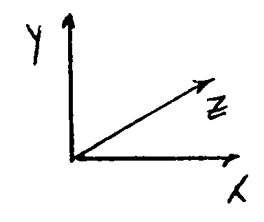
- The reflecting surfaces used rotate around the z-axis. The rotation matrix about this axis is:

- The same technique is applied to the second mirror. The complete transfer function of this mirror system may be described by:


- The desired output beam should be orthogonal or near orthogonal to the z-axis.


- Solution of this equation with respect to desired position of the output beam enables the definition of the helicoid's position. In order to simplify the construction and the solution, the angle of rotation of the first helicoid τ may be assumed equal to the angle of rotation of the second helicoid χ and both are equal to φ. This is called a symmetrical solution. If the angles are not equal, the solution will be called a general solution.
Claims (14)
- Scanning apparatus comprising: a light source (10) for providing at least one light beam (11); a medium (20) for receiving said at least one light beam; and first helical optical means (12) disposed between said light source and said medium (20); characterised by second helical optical means (14) disposed between said first helical optical means (12) and said medium, said first helical optical means receiving said at least one light beam (11) and directing it to said second helical optical means (14) which directs said at least one light beam (11) towards said medium (20); and means for rotating (25) said first and second helical optical elements in an identical direction or in an opposite direction.
- Scanning apparatus according to claim 1, characterised in that said first and second helical optical means (12, 14) have first and second specularly reflecting helical surfaces (16, 18) respectively, said first helical surface (16) being operative for receiving said at least one light beam from said light source (10) and for directing it to said second helical surface (18) and said second helical surface (18) being operative for receiving said at least one light beam from said first helical surface (16) and for directing it to said medium (20).
- Scanning apparatus according to claim 2, characterised in that said first and second helical surfaces (16, 18) have diameters of different sizes.
- Scanning apparatus according to claim 2, characterised in that said first and second helical surfaces (16, 18) have diameters of generally identical sizes.
- Scanning apparatus according to claim 2, characterised in that the first helical surface (16) is designed in a manner so that it completes one turn per scan.
- Scanning apparatus according to claim 1, characterised in that said first and second helical optical means comprise two specularly reflecting helical surfaces (134, 136) combined in a single helicoid optical element (130).
- Scanning apparatus according to claim 6, characterised by a prism (132) or two mirrors.
- Scanning apparatus according to claim 1, characterised in that said first helical optical means comprises a helicoid optical element (162) housed within a cylindrical lens (163) twisted to form a helix.
- Scanning apparatus according to claim 2, characterised in that said specularly reflecting surfaces (16, 18) are flat.
- Scanning apparatus according to claim 2, characterised in that each of said specularly reflecting surfaces (16, 18) have a constant radius of curvature.
- Scanning apparatus according to claim 2, characterised in that each of said specularly reflecting surfaces have curvatures defined by a higher than second order curve.
- Scanning apparatus according to claim 1, characterised in that said medium (20) is transparent and also including a detector (101) located near said medium for detecting light through said medium.
- Scanning apparatus according to claim 1, characterised in that said medium (20) is non-transparent and also including a detector (101) located near said medium for detecting light reflected from said medium.
- A method of scanning a medium including the steps of: providing at least one light beam (11) ; receiving said at least one light beam on a first helical optical means (12) and reflecting and shaping it to said medium; characterised by receiving said at least one light beam from said first helical optical means (12) on a second helical optical means (14) and reflecting and shaping it to said medium; and repeating said step of providing and both steps of receiving while rotating said first and second helical optical means (12, 14) in an identical direction or in opposite directions.
Applications Claiming Priority (2)
| Application Number | Priority Date | Filing Date | Title |
|---|---|---|---|
| IL95008A IL95008A0 (en) | 1990-07-09 | 1990-07-09 | Scanning apparatus and method |
| IL95008 | 1990-07-09 |
Publications (3)
| Publication Number | Publication Date |
|---|---|
| EP0466369A2 EP0466369A2 (en) | 1992-01-15 |
| EP0466369A3 EP0466369A3 (en) | 1993-02-24 |
| EP0466369B1 true EP0466369B1 (en) | 1996-02-07 |
Family
ID=11061387
Family Applications (1)
| Application Number | Title | Priority Date | Filing Date |
|---|---|---|---|
| EP91305853A Expired - Lifetime EP0466369B1 (en) | 1990-07-09 | 1991-06-27 | Scanning apparatus and method |
Country Status (7)
| Country | Link |
|---|---|
| US (1) | US5153769A (en) |
| EP (1) | EP0466369B1 (en) |
| JP (1) | JPH04234015A (en) |
| AT (1) | ATE134047T1 (en) |
| CA (1) | CA2046574A1 (en) |
| DE (1) | DE69116944T2 (en) |
| IL (1) | IL95008A0 (en) |
Families Citing this family (8)
| Publication number | Priority date | Publication date | Assignee | Title |
|---|---|---|---|---|
| DE4407228C2 (en) * | 1994-03-04 | 2003-06-26 | Ruhlatec Industrieprodukte | Playback device for electromagnetically stored data |
| US5784186A (en) * | 1996-12-04 | 1998-07-21 | National Science Council | Scanning optical delay device having a helicoid reflecting mirror |
| TW493085B (en) * | 2000-05-30 | 2002-07-01 | Matsushita Electric Industrial Co Ltd | Lightning optical device and projection video device using the same, and integrated type image device |
| DE10118392A1 (en) | 2001-04-13 | 2002-11-07 | Zeiss Carl | System and method for determining a position and / or orientation of two objects relative to one another as well as beam guidance arrangement, interferometer arrangement and device for changing an optical path length for use in such a system and method |
| US6900826B2 (en) * | 2002-02-19 | 2005-05-31 | Presstek, Inc. | Multiple resolution helical imaging system and method |
| DE10227762A1 (en) * | 2002-06-21 | 2004-02-05 | Josef Lindthaler | Light beam deflector for laser printer or copier uses rotating deflection element with radially projecting mirror band in helical path around its outside surface |
| JP2009048998A (en) * | 2007-07-19 | 2009-03-05 | Panasonic Corp | Surface light emitting device and image display device |
| DE102014104476A1 (en) | 2014-03-31 | 2015-10-01 | Ernst-Abbe-Fachhochschule Jena | Apparatus for guiding an electromagnetic beam emanating from a transmitter along a line and reversing the beam path for guiding beams emitted along a line to a receiver |
Family Cites Families (9)
| Publication number | Priority date | Publication date | Assignee | Title |
|---|---|---|---|---|
| US2529978A (en) * | 1948-04-22 | 1950-11-14 | Eastman Kodak Co | Facsimile copying apparatus |
| US3192319A (en) * | 1962-05-31 | 1965-06-29 | Hogan Faximile Corp | Facsimile phasing mechanism |
| GB978173A (en) * | 1962-07-04 | 1964-12-16 | Muirhead & Co Ltd | Improvements in or relating to facsimile telegraph apparatus |
| US3527883A (en) * | 1967-07-17 | 1970-09-08 | Stewart Warner Corp | Facsimile transceiver |
| US3523160A (en) * | 1967-08-03 | 1970-08-04 | United Aircraft Corp | Optical scanning device having a constant optical path length |
| US3553463A (en) * | 1967-11-24 | 1971-01-05 | Xerox Corp | Radiation sensitive document scanning apparatus using helical scanner |
| FR2104671B1 (en) * | 1970-06-26 | 1973-05-25 | Cit Alcatel | |
| DE2519283C2 (en) * | 1975-04-30 | 1983-10-20 | Agfa-Gevaert Ag, 5090 Leverkusen | Device for line-by-line optical scanning |
| US4494821A (en) * | 1983-03-07 | 1985-01-22 | Polaroid Corporation | Laser printing system with developable helicoid reflector |
-
1990
- 1990-07-09 IL IL95008A patent/IL95008A0/en not_active IP Right Cessation
-
1991
- 1991-06-27 AT AT91305853T patent/ATE134047T1/en not_active IP Right Cessation
- 1991-06-27 US US07/722,012 patent/US5153769A/en not_active Expired - Fee Related
- 1991-06-27 EP EP91305853A patent/EP0466369B1/en not_active Expired - Lifetime
- 1991-06-27 DE DE69116944T patent/DE69116944T2/en not_active Expired - Fee Related
- 1991-07-09 JP JP3168335A patent/JPH04234015A/en active Pending
- 1991-07-09 CA CA002046574A patent/CA2046574A1/en not_active Abandoned
Also Published As
| Publication number | Publication date |
|---|---|
| ATE134047T1 (en) | 1996-02-15 |
| EP0466369A3 (en) | 1993-02-24 |
| DE69116944D1 (en) | 1996-03-21 |
| CA2046574A1 (en) | 1992-01-10 |
| US5153769A (en) | 1992-10-06 |
| JPH04234015A (en) | 1992-08-21 |
| DE69116944T2 (en) | 1996-06-20 |
| EP0466369A2 (en) | 1992-01-15 |
| IL95008A0 (en) | 1991-06-10 |
Similar Documents
| Publication | Publication Date | Title |
|---|---|---|
| US4624528A (en) | Scanning systems with polygon scanner having curved facets | |
| US4496209A (en) | Optical beam scanning apparatus including a cylindrical lens having its opposite ends closer to the scanned plane than its medial portion | |
| US5491578A (en) | Optics for passive scan angle doubling | |
| EP0016630A1 (en) | Optical scanning apparatus | |
| US4682842A (en) | Scanning system with two reflections from scanning surface by mirrors with optical power | |
| US5153769A (en) | Scanning apparatus and method | |
| JP3269159B2 (en) | Laser scanning device and scanning lens | |
| JPH01210921A (en) | Xerographic printer capable of compensating tilt errors and scan curve errors | |
| JPS58179814A (en) | Optical beam scanner | |
| EP0550896A1 (en) | Uniform reflectance optical mirror | |
| US4662709A (en) | Wobble correction by two reflectors on an internally reflecting facet without bow | |
| US5574592A (en) | Rotatable polygon mirror | |
| US3873180A (en) | Light beam scanning system with scan angle demagnification | |
| JPH0664251B2 (en) | Rotating mirror scanner | |
| EP0138400B1 (en) | Optical scanning apparatus including polygonal scanning mirror assembly | |
| US5064261A (en) | Fθ lens systems in optical scanner | |
| EP0629891B1 (en) | Beam scanning apparatus | |
| EP0658787B1 (en) | Scanning lens and optical scanner using the same | |
| US4898437A (en) | Wobble correction by two reflections on a facet without bow | |
| US5650871A (en) | Single element optics for passive facet tracking | |
| EP0018787A1 (en) | Optical scanning apparatus | |
| JP2583716B2 (en) | Optical system laser beam scanner | |
| JP3680876B2 (en) | Optical scanning device | |
| EP0186920B1 (en) | Focus-corrected convergent beam scanner | |
| JPH1020235A (en) | Optical scanning device |
Legal Events
| Date | Code | Title | Description |
|---|---|---|---|
| PUAI | Public reference made under article 153(3) epc to a published international application that has entered the european phase |
Free format text: ORIGINAL CODE: 0009012 |
|
| AK | Designated contracting states |
Kind code of ref document: A2 Designated state(s): AT BE CH DE DK ES FR GB GR IT LI LU NL SE |
|
| PUAL | Search report despatched |
Free format text: ORIGINAL CODE: 0009013 |
|
| AK | Designated contracting states |
Kind code of ref document: A3 Designated state(s): AT BE CH DE DK ES FR GB GR IT LI LU NL SE |
|
| 17P | Request for examination filed |
Effective date: 19930511 |
|
| 17Q | First examination report despatched |
Effective date: 19941216 |
|
| GRAA | (expected) grant |
Free format text: ORIGINAL CODE: 0009210 |
|
| AK | Designated contracting states |
Kind code of ref document: B1 Designated state(s): AT BE CH DE DK ES FR GB GR IT LI LU NL SE |
|
| PG25 | Lapsed in a contracting state [announced via postgrant information from national office to epo] |
Ref country code: IT Free format text: LAPSE BECAUSE OF FAILURE TO SUBMIT A TRANSLATION OF THE DESCRIPTION OR TO PAY THE FEE WITHIN THE PRE;WARNING: LAPSES OF ITALIAN PATENTS WITH EFFECTIVE DATE BEFORE 2007 MAY HAVE OCCURRED AT ANY TIME BEFORE 2007. THE CORRECT EFFECTIVE DATE MAY BE DIFFERENT FROM THE ONE RECORDED.SCRIBED TIME-LIMIT Effective date: 19960207 Ref country code: ES Free format text: THE PATENT HAS BEEN ANNULLED BY A DECISION OF A NATIONAL AUTHORITY Effective date: 19960207 Ref country code: GR Free format text: LAPSE BECAUSE OF FAILURE TO SUBMIT A TRANSLATION OF THE DESCRIPTION OR TO PAY THE FEE WITHIN THE PRESCRIBED TIME-LIMIT Effective date: 19960207 Ref country code: CH Effective date: 19960207 Ref country code: AT Effective date: 19960207 Ref country code: DK Effective date: 19960207 Ref country code: LI Effective date: 19960207 Ref country code: NL Free format text: LAPSE BECAUSE OF FAILURE TO SUBMIT A TRANSLATION OF THE DESCRIPTION OR TO PAY THE FEE WITHIN THE PRESCRIBED TIME-LIMIT Effective date: 19960207 |
|
| REF | Corresponds to: |
Ref document number: 134047 Country of ref document: AT Date of ref document: 19960215 Kind code of ref document: T |
|
| REF | Corresponds to: |
Ref document number: 69116944 Country of ref document: DE Date of ref document: 19960321 |
|
| PG25 | Lapsed in a contracting state [announced via postgrant information from national office to epo] |
Ref country code: SE Effective date: 19960507 |
|
| PGFP | Annual fee paid to national office [announced via postgrant information from national office to epo] |
Ref country code: FR Payment date: 19960521 Year of fee payment: 6 |
|
| PGFP | Annual fee paid to national office [announced via postgrant information from national office to epo] |
Ref country code: BE Payment date: 19960524 Year of fee payment: 6 |
|
| ET | Fr: translation filed | ||
| PG25 | Lapsed in a contracting state [announced via postgrant information from national office to epo] |
Ref country code: LU Free format text: LAPSE BECAUSE OF NON-PAYMENT OF DUE FEES Effective date: 19960630 |
|
| NLV1 | Nl: lapsed or annulled due to failure to fulfill the requirements of art. 29p and 29m of the patents act | ||
| REG | Reference to a national code |
Ref country code: CH Ref legal event code: PL |
|
| PLBE | No opposition filed within time limit |
Free format text: ORIGINAL CODE: 0009261 |
|
| STAA | Information on the status of an ep patent application or granted ep patent |
Free format text: STATUS: NO OPPOSITION FILED WITHIN TIME LIMIT |
|
| 26N | No opposition filed | ||
| PGFP | Annual fee paid to national office [announced via postgrant information from national office to epo] |
Ref country code: GB Payment date: 19970513 Year of fee payment: 7 |
|
| PG25 | Lapsed in a contracting state [announced via postgrant information from national office to epo] |
Ref country code: BE Effective date: 19970630 |
|
| BERE | Be: lapsed |
Owner name: SCITEX CORP. LTD Effective date: 19970630 |
|
| PG25 | Lapsed in a contracting state [announced via postgrant information from national office to epo] |
Ref country code: FR Free format text: LAPSE BECAUSE OF NON-PAYMENT OF DUE FEES Effective date: 19980227 |
|
| REG | Reference to a national code |
Ref country code: FR Ref legal event code: ST |
|
| REG | Reference to a national code |
Ref country code: FR Ref legal event code: ST |
|
| PGFP | Annual fee paid to national office [announced via postgrant information from national office to epo] |
Ref country code: DE Payment date: 19980520 Year of fee payment: 8 |
|
| PG25 | Lapsed in a contracting state [announced via postgrant information from national office to epo] |
Ref country code: GB Free format text: LAPSE BECAUSE OF NON-PAYMENT OF DUE FEES Effective date: 19980627 |
|
| GBPC | Gb: european patent ceased through non-payment of renewal fee |
Effective date: 19980627 |
|
| PG25 | Lapsed in a contracting state [announced via postgrant information from national office to epo] |
Ref country code: DE Free format text: LAPSE BECAUSE OF NON-PAYMENT OF DUE FEES Effective date: 20000503 |