EP0466358B1 - Servovalve - Google Patents
Servovalve Download PDFInfo
- Publication number
- EP0466358B1 EP0466358B1 EP91305778A EP91305778A EP0466358B1 EP 0466358 B1 EP0466358 B1 EP 0466358B1 EP 91305778 A EP91305778 A EP 91305778A EP 91305778 A EP91305778 A EP 91305778A EP 0466358 B1 EP0466358 B1 EP 0466358B1
- Authority
- EP
- European Patent Office
- Prior art keywords
- spool
- pressure
- jet
- receptors
- feedback
- Prior art date
- Legal status (The legal status is an assumption and is not a legal conclusion. Google has not performed a legal analysis and makes no representation as to the accuracy of the status listed.)
- Expired - Lifetime
Links
- 239000012530 fluid Substances 0.000 claims description 15
- 230000000593 degrading effect Effects 0.000 description 3
- 238000006073 displacement reaction Methods 0.000 description 3
- HHNFORCFJOVQNF-UHFFFAOYSA-N cyl-1 Chemical compound N1C(=O)C(CCCCCC(=O)C2OC2)NC(=O)C2CCCN2C(=O)C(C(C)CC)NC(=O)C1CC1=CC=C(OC)C=C1 HHNFORCFJOVQNF-UHFFFAOYSA-N 0.000 description 2
- 238000011084 recovery Methods 0.000 description 2
- WANLLPADDCXPGO-WMKJBNATSA-N (6r,9s,12s)-3-[(2s)-butan-2-yl]-6-[(4-methoxyphenyl)methyl]-9-[6-(oxiran-2-yl)-6-oxohexyl]-1,4,7,10-tetrazabicyclo[10.4.0]hexadecane-2,5,8,11-tetrone Chemical compound C([C@@H]1C(=O)NC(C(N2CCCC[C@H]2C(=O)N[C@@H](CCCCCC(=O)C2OC2)C(=O)N1)=O)[C@@H](C)CC)C1=CC=C(OC)C=C1 WANLLPADDCXPGO-WMKJBNATSA-N 0.000 description 1
- 101100441844 Caenorhabditis elegans cyl-1 gene Proteins 0.000 description 1
- WANLLPADDCXPGO-UHFFFAOYSA-N Cyl-2 Natural products N1C(=O)C(CCCCCC(=O)C2OC2)NC(=O)C2CCCCN2C(=O)C(C(C)CC)NC(=O)C1CC1=CC=C(OC)C=C1 WANLLPADDCXPGO-UHFFFAOYSA-N 0.000 description 1
- 108010063406 Cyl-2 Proteins 0.000 description 1
- 101100382953 Mus musculus Ccnd1 gene Proteins 0.000 description 1
- 230000006835 compression Effects 0.000 description 1
- 238000007906 compression Methods 0.000 description 1
- 238000010276 construction Methods 0.000 description 1
- 238000001514 detection method Methods 0.000 description 1
- 238000010586 diagram Methods 0.000 description 1
- 230000008713 feedback mechanism Effects 0.000 description 1
- 238000012423 maintenance Methods 0.000 description 1
- 230000007257 malfunction Effects 0.000 description 1
- 230000007935 neutral effect Effects 0.000 description 1
- 239000007787 solid Substances 0.000 description 1
Images

Classifications
-
- F—MECHANICAL ENGINEERING; LIGHTING; HEATING; WEAPONS; BLASTING
- F15—FLUID-PRESSURE ACTUATORS; HYDRAULICS OR PNEUMATICS IN GENERAL
- F15B—SYSTEMS ACTING BY MEANS OF FLUIDS IN GENERAL; FLUID-PRESSURE ACTUATORS, e.g. SERVOMOTORS; DETAILS OF FLUID-PRESSURE SYSTEMS, NOT OTHERWISE PROVIDED FOR
- F15B13/00—Details of servomotor systems ; Valves for servomotor systems
- F15B13/16—Special measures for feedback, e.g. by a follow-up device
-
- Y—GENERAL TAGGING OF NEW TECHNOLOGICAL DEVELOPMENTS; GENERAL TAGGING OF CROSS-SECTIONAL TECHNOLOGIES SPANNING OVER SEVERAL SECTIONS OF THE IPC; TECHNICAL SUBJECTS COVERED BY FORMER USPC CROSS-REFERENCE ART COLLECTIONS [XRACs] AND DIGESTS
- Y10—TECHNICAL SUBJECTS COVERED BY FORMER USPC
- Y10T—TECHNICAL SUBJECTS COVERED BY FORMER US CLASSIFICATION
- Y10T137/00—Fluid handling
- Y10T137/2278—Pressure modulating relays or followers
- Y10T137/2322—Jet control type
-
- Y—GENERAL TAGGING OF NEW TECHNOLOGICAL DEVELOPMENTS; GENERAL TAGGING OF CROSS-SECTIONAL TECHNOLOGIES SPANNING OVER SEVERAL SECTIONS OF THE IPC; TECHNICAL SUBJECTS COVERED BY FORMER USPC CROSS-REFERENCE ART COLLECTIONS [XRACs] AND DIGESTS
- Y10—TECHNICAL SUBJECTS COVERED BY FORMER USPC
- Y10T—TECHNICAL SUBJECTS COVERED BY FORMER US CLASSIFICATION
- Y10T137/00—Fluid handling
- Y10T137/8593—Systems
- Y10T137/86493—Multi-way valve unit
- Y10T137/86574—Supply and exhaust
- Y10T137/86582—Pilot-actuated
- Y10T137/86614—Electric
-
- Y—GENERAL TAGGING OF NEW TECHNOLOGICAL DEVELOPMENTS; GENERAL TAGGING OF CROSS-SECTIONAL TECHNOLOGIES SPANNING OVER SEVERAL SECTIONS OF THE IPC; TECHNICAL SUBJECTS COVERED BY FORMER USPC CROSS-REFERENCE ART COLLECTIONS [XRACs] AND DIGESTS
- Y10—TECHNICAL SUBJECTS COVERED BY FORMER USPC
- Y10T—TECHNICAL SUBJECTS COVERED BY FORMER US CLASSIFICATION
- Y10T137/00—Fluid handling
- Y10T137/8593—Systems
- Y10T137/86493—Multi-way valve unit
- Y10T137/86815—Multiple inlet with single outlet
Definitions
- This invention relates generally to electrohydraulic servovalves and more particularly to a jet pipe electrohydraulic servovalve which includes pressure gain compensation for the first stage thereof, according to the preamble of claim 1, as disclosed in DE-A-1 600 807.
- both the pressure gain and flow gain rise rather sharply upon the application of appropriate electrical signals to the torque motor causing movement of the ejector jet relative to the receptors in the servovalve.
- both pressure and flow gain track each other closely. It has been found that in some applications, rapid rises in pressure, that is steep pressure gain, may generate unwanted signals. For example, in redundant control systems such rapid rises in pressure may appear to detection portions of the system as a failure or malfunction in one or more portions of the system. It has thus been determined that in some applications single stage jet pipe servovalves or the first stage of multi-stage valves, it is desireable to compensate such pressure gain by reducing the level thereof without at the same time degrading the flow gain characteristics of the valve.
- the present invention provides differential pressure gain compensation for single stage jet pipe servovalves or in the first stage of multiple stage jet pipe servovalves so as to maintain a relatively low level of pressure gain without degrading the flow gain thereof. Such is accomplished by providing a mechanical feedback source which is proportional to the pressure differential between the receptors of the jet pipe servovalve.
- a servovalve constructed in accordance with present invention includes an ejector jet disposed opposed first and second receptors which receive fluid from the ejector jet responsive to movement of the ejector jet by a torque motor which has electrical control signals applied thereto.
- a pair of output ports is connected to the receptors for applying fluid received thereby to a load.
- Spool means is mounted for reciprocal movement and has the fluid pressure at the receptors connected across opposite ends of the spool so as to move the spool responsive to pressure differential thereacross. There are no other fluid pressure connections to the spool means.
- a mechanical feedback means is connected between the spool means and the ejector jet for applying a force feedback to the ejector jet which is proportional to the pressure differential across the receptors and is opposite the force applied by the torque motor to thereby compensate for pressure gain.
- FIGURES 1 through 6 there is illustrated a pressure gain compensation jet pipe servovalve constructed in accordance with the principles of the present invention.
- the various figures are schematic representations or partial illustrations of the structures involved emphasizing only the specific features of the present invention. Jet pipe servovalves are well known in the prior art and details of the construction thereof are not shown or described herein. As opposed to such description and illustration, applicants hereby incorporate by reference the disclosures of U.S. Patents 3,437,101; 3,584,649 and 4,201,114 as illustrative of jet pipe servovalves to which the features of the present invention may be applied.
- a jet pipe servovalve 10 includes a feed pipe 55 terminated by an ejector jet 12 and a pair of receptors 14 and 16 which are disposed opposed the ejector jet 12.
- a source of fluid under pressure 18 is connected to the feed pipe 55 so that fluid from the source will flow from the ejector jet 12 and impinge upon the receptors 14 and 16.
- a torque motor 20 has electrical signals applied thereto from a signal source 22 as is well known in the prior art.
- the torque motor applies a force to the ejector jet 12 causing it to rotate relative to the receptors 14 and 16 thereby applying more or less fluid under pressure to the individual receptors 14 and 16 depending upon the position of the ejector jet 12 relative to the receptors 14 and 16 as is well known in the prior art.
- a pair of ports C1 and C2 are connected to the receptors 14 and 16 respectively so that the fluid under pressure received by the receptors 14 and 16 may be applied to any desired load such as is schematically illustrated at 24.
- the load 24 is the second stage of a jet pipe servovalve
- a mechanical feedback wire such as illustrated at 26 may be connected between the second stage of the valve and the ejector jet 12.
- Jet pipe servovalves as thus far described are well known in the prior art. Utilizing such valves, the first-stage flow and pressure response to the application of rated current from the signal source 22 to the torque motor 20 for a high flow gain jet pipe servovalve is as shown at 28 and 30 in FIGURE 2.
- the curve 28 is representative of flow in response to the application of rated current while the dashed line 30 is representative of pressure in response to the application of rated current.
- the pressure feedback apparatus includes a spool means 36 which is spring centered by utilization of the springs 38 and 40 to maintain the spool centered in the absence of a pressure differential thereacross.
- the pressure appearing at the receptors 14 and 16 are applied to the ends 42 and 44 of the spool 36. If pressure differences exist between the receptors 14 and 16, the spool 36 will reciprocate responsive thereto.
- the springs 38 and 40 are sized to provide predetermined movement of the spool 36 proportional to the differential pressure across the spool 36.
- Mechanical feedback means in the form of a feedback wire 46 is connected between the ejector 12 and the spool 36.
- a mechanical force is applied to the ejector 12 which is opposite the force applied thereto by the torque motor 20.
- the ejector jet 12 is maintained in a position over the receptors 14 and 16 such that the spool displacement and hence the feedback torque counteracts the torque generated by the torque motor.
- the net result of this torque balance is a reduced pressure gain as is shown in FIGURE 2 at 32.
- the servovalve includes a torque motor 50 having an armature 52 which is in turn connected to a flexure tube 54 to which the feed pipe 55 which feeds fluid to the ejector jet 12 is connected.
- the receptors 14 and 16 are disposed within an appropriate structure 56.
- the feedback wires 26 and 46 are affixed to the feed pipe 55 by an appropriate fitting or attaching clamp 58.
- the spool 36 is reciprocally mounted within a bore 60 disposed within the housing 62. As is more clearly shown in FIGURE 4, the springs 38 and 40 are disposed within the bore 60 and maintain the spool 28 centrally disposed in the absence of differential pressure thereacross.
- a fitting 58 includes an aperture 64 which receives the feed pipe 55.
- the external feedback spring 26 which is utilized for interconnection with the load 24, if desired, is affixed to the fitting 58 as is the internal feedback spring 46.
- the external feedback wire 26 provides load spool 24 position feedback to the feed pipe 55.
- Each of the feedback springs 26 and 46 includes a spherical end section 66 and 68 respectively which is disposed within a slot or opening formed within the respective spool or load as the case may be.
- the spherical end 68 hash a flat 70 formed thereon to provide a proper interface with the spool 36 as will become more apparent in conjunction with FIGURE 6 hereinafter.
- the fitting 58 is disposed upon the feed pipe 55 which carries the ejector jet, and is secured in place by an appropriate fastening apparatus which passes through the aperture 72 .
- the fastening apparatus also securely clamps the feedback wires 26 and 46 in place.
- the spool 36 is reciprocally disposed within a sleeve 74 which in turn is disposed within the bore 60 provided within the housing 62.
- a central groove 76 is provided in the spool 36 to receive the spherical ball 68 disposed at the end of the feedback spring 46.
- the external feedback wire 26 extends through an opening 78 provided in the housing 62.
- the opening 78 is connected to system return and thus allows any leakage past the spool 36 which may occur to return to the source of fluid 18 as is well known in the prior art.
- the ejector/receptor region of the valve is ported to system return as by connection to the opening 78.
- the bore 60 is appropriately sealed at each end thereof by threaded plugs 80 and 82 along with O-rings 84 and 86.
- Springs 38 and 40 are secured in place between the ends of the plugs 80 and 82 respectively and retainers 88 and 90 which contact the ends 42 and 44 of the spool to thereby retain the spool in a central neutral position in the absence of the application of differential pressure to the ends 42 and 44 of the spool 36.
- FIGURE 7 is depicted with the armature 52 rotating 90 degrees to the plane of the paper upon which the drawing is made while FIGURE 8 is rotated 90 degrees thereto.
- a p *(P1-P2) 2*k s *x + k2*(x+x j ) where;
- K t *i (k O -k m )*a + k1*l1*a*(l1-l2)- k2*l3*a*(l1-l2)
Landscapes
- Engineering & Computer Science (AREA)
- Physics & Mathematics (AREA)
- Fluid Mechanics (AREA)
- Mechanical Engineering (AREA)
- General Engineering & Computer Science (AREA)
- Servomotors (AREA)
Description
- This invention relates generally to electrohydraulic servovalves and more particularly to a jet pipe electrohydraulic servovalve which includes pressure gain compensation for the first stage thereof, according to the preamble of claim 1, as disclosed in DE-A-1 600 807.
- Typically in high flow gain single-stage jet pipe servovalves, both the pressure gain and flow gain rise rather sharply upon the application of appropriate electrical signals to the torque motor causing movement of the ejector jet relative to the receptors in the servovalve. Traditionally, both pressure and flow gain track each other closely. It has been found that in some applications, rapid rises in pressure, that is steep pressure gain, may generate unwanted signals. For example, in redundant control systems such rapid rises in pressure may appear to detection portions of the system as a failure or malfunction in one or more portions of the system. It has thus been determined that in some applications single stage jet pipe servovalves or the first stage of multi-stage valves, it is desireable to compensate such pressure gain by reducing the level thereof without at the same time degrading the flow gain characteristics of the valve.
- The present invention provides differential pressure gain compensation for single stage jet pipe servovalves or in the first stage of multiple stage jet pipe servovalves so as to maintain a relatively low level of pressure gain without degrading the flow gain thereof. Such is accomplished by providing a mechanical feedback source which is proportional to the pressure differential between the receptors of the jet pipe servovalve.
- Pressure feedback in electrohydraulic servovalves is well known in the prior art and the best known such prior art is reflected in United States Patents 3,398,647 and 3,487,750. The devices disclosed in each of these two prior art patents generate a mechanical feedback signal responsive to load pressure at the utilizing apparatus. The mechanical feedback signal is then applied to the servo control system. Although these prior art devices develop mechanical feedback signals responsive to pressure at the load, applicants are unaware of any prior art devices which utilize a mechanical feedback signal proportional to pressure differential at the receptors for purposes of compensating pressure gain.
- A servovalve constructed in accordance with present invention includes an ejector jet disposed opposed first and second receptors which receive fluid from the ejector jet responsive to movement of the ejector jet by a torque motor which has electrical control signals applied thereto. A pair of output ports is connected to the receptors for applying fluid received thereby to a load. Spool means is mounted for reciprocal movement and has the fluid pressure at the receptors connected across opposite ends of the spool so as to move the spool responsive to pressure differential thereacross. There are no other fluid pressure connections to the spool means. A mechanical feedback means is connected between the spool means and the ejector jet for applying a force feedback to the ejector jet which is proportional to the pressure differential across the receptors and is opposite the force applied by the torque motor to thereby compensate for pressure gain.
-
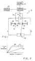
- FIGURE 1 is a schematic diagram of an electrohydraulic servovalve constructed in accordance with the principals of the present invention;
- FIGURE 2 is a graph illustrating pressure compensation effected by the structure of FIGURE 1;
- FIGURE 3 is a side view partly in cross section of a servovalve constructed in accordance with the principals of the present invention;
- FIGURE 4 is a side elevation partly in cross section taken about the lines 4-4 of FIGURE 3;
- FIGURE 5 is a view partly in cross section illustrating the feedback wires utilized in the structure shown in FIGURES 3 and 4;
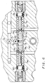
- FIGURE 6 is a top view partially in cross section illustrating the interconnection of the feedback wire with the spool valve;
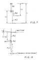
- FIGURES 7 and 8 are schematic illustrations showing the operation of the feedback wires and the various forces encountered in providing the pressure compensation in accordance with the principals of the present invention.
- By reference to FIGURES 1 through 6, there is illustrated a pressure gain compensation jet pipe servovalve constructed in accordance with the principles of the present invention. The various figures are schematic representations or partial illustrations of the structures involved emphasizing only the specific features of the present invention. Jet pipe servovalves are well known in the prior art and details of the construction thereof are not shown or described herein. As opposed to such description and illustration, applicants hereby incorporate by reference the disclosures of U.S. Patents 3,437,101; 3,584,649 and 4,201,114 as illustrative of jet pipe servovalves to which the features of the present invention may be applied.
- Referring now more specifically to FIGURE 1, there is provided a schematic representation of a pressure compensated jet pipe servovalve of the present invention. As is therein shown, a
jet pipe servovalve 10 includes a feed pipe 55 terminated by an ejector jet 12 and a pair ofreceptors pressure 18 is connected to the feed pipe 55 so that fluid from the source will flow from the ejector jet 12 and impinge upon thereceptors torque motor 20 has electrical signals applied thereto from asignal source 22 as is well known in the prior art. Responsive to the application of signals from thesource 22, the torque motor applies a force to the ejector jet 12 causing it to rotate relative to thereceptors individual receptors receptors receptors receptors - As is well known in the art, if the
load 24 is the second stage of a jet pipe servovalve, then a mechanical feedback wire such as illustrated at 26 may be connected between the second stage of the valve and the ejector jet 12. Jet pipe servovalves as thus far described are well known in the prior art. Utilizing such valves, the first-stage flow and pressure response to the application of rated current from thesignal source 22 to thetorque motor 20 for a high flow gain jet pipe servovalve is as shown at 28 and 30 in FIGURE 2. Thecurve 28 is representative of flow in response to the application of rated current while thedashed line 30 is representative of pressure in response to the application of rated current. It can be seen by reference to thecurves receptors - In various applications, it is desirable to maintain the flow as illustrated in FIGURE 2 but to provide compensation for the pressure gain so that full rated pressure is not realized until substantially full rated current is applied. Such a relationship between pressure and rated current is shown by the solid curve 32. Through utilization of such capabilities, it can be seen that high flow gain as shown by the
curve 28 can be realized while at the same time reducing the pressure gain as shown by the curve 32. - To accomplish the desired maintenance of flow gain but with reduced pressure gain, an appropriate pressure feedback apparatus is incorporated into the servovalve and is illustrated in FIGURE 1 at 34. The pressure feedback apparatus includes a spool means 36 which is spring centered by utilization of the
springs receptors ends spool 36. If pressure differences exist between thereceptors spool 36 will reciprocate responsive thereto. Thesprings spool 36 proportional to the differential pressure across thespool 36. Mechanical feedback means in the form of afeedback wire 46 is connected between the ejector 12 and thespool 36. As thespool 36 reciprocates responsive to the differential pressures applied thereacross by thereceptors torque motor 20. As a result, the ejector jet 12 is maintained in a position over thereceptors - If the ports C1 and C2 are either interconnected one to the other or are placed under a no load flow condition (that is the
load 24 is disconnected), then no pressure differential exists across the receptors 14-16 and likewise no pressure differential exists at theends spool 36. Therefore, as the ejector jet 12 moves responsive to signals from thesource 22, thespool 36 does not reciprocate and the force feedback to the ejector jet 12 is limited to the feedback produced by the small displacement of the ejector jet 12 acting against thefeedback wire 46. - By reference now to FIGURES 3 through 6, there is illustrated a jet pipe servovalve constructed in accordance with the principals of the present invention but without a load connected thereto. As is illustrated, the servovalve includes a
torque motor 50 having anarmature 52 which is in turn connected to aflexure tube 54 to which the feed pipe 55 which feeds fluid to the ejector jet 12 is connected. Thereceptors appropriate structure 56. Thefeedback wires clamp 58. Thespool 36 is reciprocally mounted within abore 60 disposed within thehousing 62. As is more clearly shown in FIGURE 4, thesprings bore 60 and maintain thespool 28 centrally disposed in the absence of differential pressure thereacross. - Referring now more particularly to FIGURE 5, the arrangement of the mechanical feedback mechanisms in the form of the
springs fitting 58 includes anaperture 64 which receives the feed pipe 55. Theexternal feedback spring 26 which is utilized for interconnection with theload 24, if desired, is affixed to thefitting 58 as is theinternal feedback spring 46. As is well known to those skilled in the art theexternal feedback wire 26 providesload spool 24 position feedback to the feed pipe 55. Each of the feedback springs 26 and 46 includes aspherical end section spherical end 68 hash a flat 70 formed thereon to provide a proper interface with thespool 36 as will become more apparent in conjunction with FIGURE 6 hereinafter. The fitting 58 is disposed upon the feed pipe 55 which carries the ejector jet, and is secured in place by an appropriate fastening apparatus which passes through theaperture 72 . At the same time, the fastening apparatus also securely clamps thefeedback wires - As is seen more specifically in FIGURE 6, the
spool 36 is reciprocally disposed within asleeve 74 which in turn is disposed within thebore 60 provided within thehousing 62. Acentral groove 76 is provided in thespool 36 to receive thespherical ball 68 disposed at the end of thefeedback spring 46. Theexternal feedback wire 26 extends through anopening 78 provided in thehousing 62. Theopening 78 is connected to system return and thus allows any leakage past thespool 36 which may occur to return to the source offluid 18 as is well known in the prior art. As is also well known the ejector/receptor region of the valve is ported to system return as by connection to theopening 78. - The
bore 60 is appropriately sealed at each end thereof by threadedplugs rings Springs plugs retainers 88 and 90 which contact the ends 42 and 44 of the spool to thereby retain the spool in a central neutral position in the absence of the application of differential pressure to theends spool 36. - During the time that the ports C1 and C2 are blocked, that is, a load device is connected thereto, the torque motor output torque must balance the flexure tube torque, the torque applied to the ejector from the
pressure feedback wire 46 and if present, torque from theexternal feedback wire 26. This torque balance is represented by the following equation.

where; - Kt
- = Torque Motor Gain (in-lb/amp)
- i
- = Input Current (amp)
- k₀
- = Spring Rate, Flexure Tube (in-lb/rad)
- km
- = Spring Rate, Torque Motor Magnetic (in-lb/rad)
- a
- = Armature Rotation (rad)
- k₁
- = Spring Rate, External Feedback Wire (lbf/in)
- k₂
- = Spring Rate, Feedback Wire, Pressure Feedback (lbf/in)
- l₁
- = Length, Armature Pivot to External Feedback Wire Ball Center (inch)
- l₂
- = Length, External Feedback Wire Mount to Ball Center (inch)
- l₃
- = Length, Armature Pivot to Pressure Feedback Feedback Wire Ball Center (inch)
- x
- = Spool Stroke (inch) Feedback spool
- The various elements of the equation set forth above are taken from the structure as illustrated in FIGURES 7 and 8 to which reference is hereby made. FIGURE 7 is depicted with the
armature 52 rotating 90 degrees to the plane of the paper upon which the drawing is made while FIGURE 8 is rotated 90 degrees thereto.
For status equilibrium of the pressure feedback spool, the following force equation must be satisfied:

where; - Ap
- = Spool Area (inch squared)
- P₁
- = Recovery Pressure Cyl 1 (psig)
- P₂
- = Recovery Pressure Cyl 2 (psig)
- ks
- = Spring Rate, Compression Spring (lbf/in)
- xj
- = Jet Displacement, corresponding to P₁ and P₂ (inch)
- X
- = Stroke, External Feedback wire (inch)
- The flow gain torque balance for the structure as illustrated in FIGURES 7 and 8 is represented by the following equation.
-

This equation is valid so long as the armature is rotating and has not contacted the stops provided therefor. The various elements of the equation immediately set forth are the same as those defined with respect to the pressure gain torque balance equation. - There has thus been disclosed a jet pipe servovalve which provides compensated pressure gain without degrading flow gain.

where;
Claims (4)
- A jet pipe servovalve having pressure gain compensation comprising:
a source of fluid under pressure (18);
an ejector jet means (12) connected to said source of fluid;
first and second receptors (14,16) disposed to receive fluid from said ejector jet;
a torque motor (20) connected to said ejector jet for generating force moving said ejector jet relative to said receptors responsive to electrical signals applied to said torque motor;
first and second output ports (C1,C2) connected to said first and second receptors
spool means (36) having first and second ends mounted for reciprocal movement;
means connecting said fluid at said first and second receptors to said first and second ends of said spool means respectively for moving said spool means responsive to pressure differential between said first and second receptors, mechanical feedback means (46) connected between said spool and said ejector jet for applying force feedback to said ejector jet proportional to said
pressure differential and opposite the force applied by said torque motor to thereby compensate pressure gain of said servovalve. characterised by there being no other pressure fluid connection to said spool means; and by said receptors being directly connected to a load (24) - A jet pipe servovalve as defined in claim 1 wherein said spool means includes spring means (38,40) disposed at each end of said spool means for maintaining said spool means centered in the absence of a pressure differential applied thereto.
- A jet pipe servovalve as defined in claim 2 wherein said mechanical feedback means is a feedback wire connected between said ejector jet and said spool means.
- A jet pipe servovalve as defined in claim 3 which further includes second mechanical feedback (26) means affixed to said ejector jet means for connection to said load means.
Applications Claiming Priority (2)
| Application Number | Priority Date | Filing Date | Title |
|---|---|---|---|
| US07/552,737 US5031653A (en) | 1990-07-12 | 1990-07-12 | Differential cylinder pressure gain compensation for single stage servovalve |
| US552737 | 1990-07-12 |
Publications (2)
| Publication Number | Publication Date |
|---|---|
| EP0466358A1 EP0466358A1 (en) | 1992-01-15 |
| EP0466358B1 true EP0466358B1 (en) | 1994-10-12 |
Family
ID=24206592
Family Applications (1)
| Application Number | Title | Priority Date | Filing Date |
|---|---|---|---|
| EP91305778A Expired - Lifetime EP0466358B1 (en) | 1990-07-12 | 1991-06-26 | Servovalve |
Country Status (4)
| Country | Link |
|---|---|
| US (1) | US5031653A (en) |
| EP (1) | EP0466358B1 (en) |
| JP (1) | JPH05209602A (en) |
| DE (1) | DE69104565T2 (en) |
Families Citing this family (5)
| Publication number | Priority date | Publication date | Assignee | Title |
|---|---|---|---|---|
| US5653342A (en) * | 1995-12-22 | 1997-08-05 | Eaton; James B. | Enclosure for carrying and protecting a golf scorecard |
| US5573036A (en) * | 1996-01-11 | 1996-11-12 | Sargent Controls & Aerospace/Dover Diversified Inc. | Electro-hydraulic servovalve having mechanical feedback |
| JP5981567B2 (en) | 2012-02-09 | 2016-08-31 | ムーグ インコーポレーテッド | Electro-hydraulic servo valve |
| BR112014020497B1 (en) | 2012-02-23 | 2021-03-09 | Moog Inc | direct drive servo valve |
| CN119244667A (en) * | 2024-10-15 | 2025-01-03 | 上海衡拓液压控制技术有限公司 | A brake servo valve pre-stage pressure gain compensation device |
Family Cites Families (9)
| Publication number | Priority date | Publication date | Assignee | Title |
|---|---|---|---|---|
| US3017864A (en) * | 1958-08-18 | 1962-01-23 | American Brake Shoe Co | Valve |
| US3054388A (en) * | 1961-07-03 | 1962-09-18 | Bell Aerospace Corp | Servo valve with flow rate feedback |
| US3437101A (en) * | 1966-03-01 | 1969-04-08 | Abex Corp | Servovalve construction |
| US3464318A (en) * | 1966-06-03 | 1969-09-02 | Moog Inc | Servomechanism providing static load error washout |
| DE1600807B2 (en) * | 1967-05-24 | 1971-01-21 | H M. Hobson Ltd.. London | Electro-hydraulic control monitor with feedback |
| GB1272859A (en) * | 1969-11-25 | 1972-05-03 | Hobson Ltd H M | Improvements in position control servo systems |
| JPS4956096A (en) * | 1972-09-29 | 1974-05-30 | ||
| US4368750A (en) * | 1978-04-28 | 1983-01-18 | Sundstrand Corporation | Ball-type feedback motor for servovalves |
| GB8621532D0 (en) * | 1986-09-06 | 1986-10-15 | Dowty Hydraulic Units Ltd | Fluid control devices |
-
1990
- 1990-07-12 US US07/552,737 patent/US5031653A/en not_active Expired - Fee Related
-
1991
- 1991-06-26 DE DE69104565T patent/DE69104565T2/en not_active Expired - Fee Related
- 1991-06-26 EP EP91305778A patent/EP0466358B1/en not_active Expired - Lifetime
- 1991-06-28 JP JP3158306A patent/JPH05209602A/en active Pending
Also Published As
| Publication number | Publication date |
|---|---|
| JPH05209602A (en) | 1993-08-20 |
| US5031653A (en) | 1991-07-16 |
| DE69104565D1 (en) | 1994-11-17 |
| DE69104565T2 (en) | 1995-05-18 |
| EP0466358A1 (en) | 1992-01-15 |
Similar Documents
| Publication | Publication Date | Title |
|---|---|---|
| US4907680A (en) | Semi-active damper piston valve assembly | |
| US3992979A (en) | Hydraulic actuating arrangements | |
| EP0087773B1 (en) | Variable displacement pump control system and a valve for such system | |
| JPS5834208A (en) | Single stage servo valve | |
| JPS59103003A (en) | Hydraulic-pneumatic type drive | |
| US4276809A (en) | Simplified fail-fixed servovalve | |
| US2909195A (en) | Servo valve | |
| CA1255996A (en) | Servo system method and apparatus, servo valve apparatus therefor and method of making same | |
| US3279323A (en) | Electrohydraulic actuator | |
| US5031653A (en) | Differential cylinder pressure gain compensation for single stage servovalve | |
| GB2228108A (en) | Fluid-controlled servo-apparatus | |
| US4631923A (en) | Solenoid operated check valve | |
| US3487750A (en) | Positioning system having input signal integrator and load pressure feedback | |
| EP1304488A2 (en) | Membrane-activated hydraulic actuator | |
| US3245424A (en) | Servo valve | |
| US4817498A (en) | Dynamic characteristic compensating device for electrical hydraulic servo actuator | |
| EP0828946A1 (en) | Hdyraulic actuating unit | |
| US4719942A (en) | Hydraulic valve assembly | |
| US3000363A (en) | Two stage hydraulic servo valve | |
| US4519573A (en) | Device for the actuation of a slide valve | |
| US4316597A (en) | Compact valve actuator | |
| EP0370070B1 (en) | Synthetisized flow-control servovalve | |
| US2958503A (en) | Bellows compensation for servo valve | |
| US3488029A (en) | Return pressure compensated hydraeric signal comparator | |
| US2996072A (en) | Actuator |
Legal Events
| Date | Code | Title | Description |
|---|---|---|---|
| PUAI | Public reference made under article 153(3) epc to a published international application that has entered the european phase |
Free format text: ORIGINAL CODE: 0009012 |
|
| AK | Designated contracting states |
Kind code of ref document: A1 Designated state(s): DE FR GB IT |
|
| 17P | Request for examination filed |
Effective date: 19920709 |
|
| 17Q | First examination report despatched |
Effective date: 19940125 |
|
| GRAA | (expected) grant |
Free format text: ORIGINAL CODE: 0009210 |
|
| AK | Designated contracting states |
Kind code of ref document: B1 Designated state(s): DE FR GB IT |
|
| REF | Corresponds to: |
Ref document number: 69104565 Country of ref document: DE Date of ref document: 19941117 |
|
| ITF | It: translation for a ep patent filed | ||
| ET | Fr: translation filed | ||
| PLBE | No opposition filed within time limit |
Free format text: ORIGINAL CODE: 0009261 |
|
| STAA | Information on the status of an ep patent application or granted ep patent |
Free format text: STATUS: NO OPPOSITION FILED WITHIN TIME LIMIT |
|
| 26N | No opposition filed | ||
| PGFP | Annual fee paid to national office [announced via postgrant information from national office to epo] |
Ref country code: FR Payment date: 19980408 Year of fee payment: 8 |
|
| PGFP | Annual fee paid to national office [announced via postgrant information from national office to epo] |
Ref country code: GB Payment date: 19980417 Year of fee payment: 8 |
|
| PGFP | Annual fee paid to national office [announced via postgrant information from national office to epo] |
Ref country code: DE Payment date: 19980429 Year of fee payment: 8 |
|
| PG25 | Lapsed in a contracting state [announced via postgrant information from national office to epo] |
Ref country code: GB Free format text: LAPSE BECAUSE OF NON-PAYMENT OF DUE FEES Effective date: 19990626 |
|
| PG25 | Lapsed in a contracting state [announced via postgrant information from national office to epo] |
Ref country code: FR Free format text: THE PATENT HAS BEEN ANNULLED BY A DECISION OF A NATIONAL AUTHORITY Effective date: 19990630 |
|
| GBPC | Gb: european patent ceased through non-payment of renewal fee |
Effective date: 19990626 |
|
| PG25 | Lapsed in a contracting state [announced via postgrant information from national office to epo] |
Ref country code: DE Free format text: LAPSE BECAUSE OF NON-PAYMENT OF DUE FEES Effective date: 20000503 |
|
| REG | Reference to a national code |
Ref country code: FR Ref legal event code: ST |
|
| PG25 | Lapsed in a contracting state [announced via postgrant information from national office to epo] |
Ref country code: IT Free format text: LAPSE BECAUSE OF NON-PAYMENT OF DUE FEES;WARNING: LAPSES OF ITALIAN PATENTS WITH EFFECTIVE DATE BEFORE 2007 MAY HAVE OCCURRED AT ANY TIME BEFORE 2007. THE CORRECT EFFECTIVE DATE MAY BE DIFFERENT FROM THE ONE RECORDED. Effective date: 20050626 |