EP0464799B1 - Sliding member and method for producing the same by gas sulphonitriding - Google Patents
Sliding member and method for producing the same by gas sulphonitriding Download PDFInfo
- Publication number
- EP0464799B1 EP0464799B1 EP91111045A EP91111045A EP0464799B1 EP 0464799 B1 EP0464799 B1 EP 0464799B1 EP 91111045 A EP91111045 A EP 91111045A EP 91111045 A EP91111045 A EP 91111045A EP 0464799 B1 EP0464799 B1 EP 0464799B1
- Authority
- EP
- European Patent Office
- Prior art keywords
- gas
- temperature
- heat treatment
- sulphonitriding
- hydrogen sulfide
- Prior art date
- Legal status (The legal status is an assumption and is not a legal conclusion. Google has not performed a legal analysis and makes no representation as to the accuracy of the status listed.)
- Expired - Lifetime
Links
Images



Classifications
-
- C—CHEMISTRY; METALLURGY
- C23—COATING METALLIC MATERIAL; COATING MATERIAL WITH METALLIC MATERIAL; CHEMICAL SURFACE TREATMENT; DIFFUSION TREATMENT OF METALLIC MATERIAL; COATING BY VACUUM EVAPORATION, BY SPUTTERING, BY ION IMPLANTATION OR BY CHEMICAL VAPOUR DEPOSITION, IN GENERAL; INHIBITING CORROSION OF METALLIC MATERIAL OR INCRUSTATION IN GENERAL
- C23C—COATING METALLIC MATERIAL; COATING MATERIAL WITH METALLIC MATERIAL; SURFACE TREATMENT OF METALLIC MATERIAL BY DIFFUSION INTO THE SURFACE, BY CHEMICAL CONVERSION OR SUBSTITUTION; COATING BY VACUUM EVAPORATION, BY SPUTTERING, BY ION IMPLANTATION OR BY CHEMICAL VAPOUR DEPOSITION, IN GENERAL
- C23C8/00—Solid state diffusion of only non-metal elements into metallic material surfaces; Chemical surface treatment of metallic material by reaction of the surface with a reactive gas, leaving reaction products of surface material in the coating, e.g. conversion coatings, passivation of metals
- C23C8/06—Solid state diffusion of only non-metal elements into metallic material surfaces; Chemical surface treatment of metallic material by reaction of the surface with a reactive gas, leaving reaction products of surface material in the coating, e.g. conversion coatings, passivation of metals using gases
- C23C8/34—Solid state diffusion of only non-metal elements into metallic material surfaces; Chemical surface treatment of metallic material by reaction of the surface with a reactive gas, leaving reaction products of surface material in the coating, e.g. conversion coatings, passivation of metals using gases more than one element being applied in more than one step
-
- C—CHEMISTRY; METALLURGY
- C23—COATING METALLIC MATERIAL; COATING MATERIAL WITH METALLIC MATERIAL; CHEMICAL SURFACE TREATMENT; DIFFUSION TREATMENT OF METALLIC MATERIAL; COATING BY VACUUM EVAPORATION, BY SPUTTERING, BY ION IMPLANTATION OR BY CHEMICAL VAPOUR DEPOSITION, IN GENERAL; INHIBITING CORROSION OF METALLIC MATERIAL OR INCRUSTATION IN GENERAL
- C23C—COATING METALLIC MATERIAL; COATING MATERIAL WITH METALLIC MATERIAL; SURFACE TREATMENT OF METALLIC MATERIAL BY DIFFUSION INTO THE SURFACE, BY CHEMICAL CONVERSION OR SUBSTITUTION; COATING BY VACUUM EVAPORATION, BY SPUTTERING, BY ION IMPLANTATION OR BY CHEMICAL VAPOUR DEPOSITION, IN GENERAL
- C23C8/00—Solid state diffusion of only non-metal elements into metallic material surfaces; Chemical surface treatment of metallic material by reaction of the surface with a reactive gas, leaving reaction products of surface material in the coating, e.g. conversion coatings, passivation of metals
- C23C8/06—Solid state diffusion of only non-metal elements into metallic material surfaces; Chemical surface treatment of metallic material by reaction of the surface with a reactive gas, leaving reaction products of surface material in the coating, e.g. conversion coatings, passivation of metals using gases
- C23C8/28—Solid state diffusion of only non-metal elements into metallic material surfaces; Chemical surface treatment of metallic material by reaction of the surface with a reactive gas, leaving reaction products of surface material in the coating, e.g. conversion coatings, passivation of metals using gases more than one element being applied in one step
-
- F—MECHANICAL ENGINEERING; LIGHTING; HEATING; WEAPONS; BLASTING
- F16—ENGINEERING ELEMENTS AND UNITS; GENERAL MEASURES FOR PRODUCING AND MAINTAINING EFFECTIVE FUNCTIONING OF MACHINES OR INSTALLATIONS; THERMAL INSULATION IN GENERAL
- F16C—SHAFTS; FLEXIBLE SHAFTS; ELEMENTS OR CRANKSHAFT MECHANISMS; ROTARY BODIES OTHER THAN GEARING ELEMENTS; BEARINGS
- F16C33/00—Parts of bearings; Special methods for making bearings or parts thereof
- F16C33/02—Parts of sliding-contact bearings
- F16C33/04—Brasses; Bushes; Linings
- F16C33/06—Sliding surface mainly made of metal
- F16C33/12—Structural composition; Use of special materials or surface treatments, e.g. for rust-proofing
-
- F—MECHANICAL ENGINEERING; LIGHTING; HEATING; WEAPONS; BLASTING
- F16—ENGINEERING ELEMENTS AND UNITS; GENERAL MEASURES FOR PRODUCING AND MAINTAINING EFFECTIVE FUNCTIONING OF MACHINES OR INSTALLATIONS; THERMAL INSULATION IN GENERAL
- F16C—SHAFTS; FLEXIBLE SHAFTS; ELEMENTS OR CRANKSHAFT MECHANISMS; ROTARY BODIES OTHER THAN GEARING ELEMENTS; BEARINGS
- F16C33/00—Parts of bearings; Special methods for making bearings or parts thereof
- F16C33/02—Parts of sliding-contact bearings
- F16C33/04—Brasses; Bushes; Linings
- F16C33/06—Sliding surface mainly made of metal
- F16C33/14—Special methods of manufacture; Running-in
-
- F—MECHANICAL ENGINEERING; LIGHTING; HEATING; WEAPONS; BLASTING
- F16—ENGINEERING ELEMENTS AND UNITS; GENERAL MEASURES FOR PRODUCING AND MAINTAINING EFFECTIVE FUNCTIONING OF MACHINES OR INSTALLATIONS; THERMAL INSULATION IN GENERAL
- F16J—PISTONS; CYLINDERS; SEALINGS
- F16J1/00—Pistons; Trunk pistons; Plungers
- F16J1/02—Bearing surfaces
-
- F—MECHANICAL ENGINEERING; LIGHTING; HEATING; WEAPONS; BLASTING
- F16—ENGINEERING ELEMENTS AND UNITS; GENERAL MEASURES FOR PRODUCING AND MAINTAINING EFFECTIVE FUNCTIONING OF MACHINES OR INSTALLATIONS; THERMAL INSULATION IN GENERAL
- F16J—PISTONS; CYLINDERS; SEALINGS
- F16J10/00—Engine or like cylinders; Features of hollow, e.g. cylindrical, bodies in general
- F16J10/02—Cylinders designed to receive moving pistons or plungers
- F16J10/04—Running faces; Liners
-
- F—MECHANICAL ENGINEERING; LIGHTING; HEATING; WEAPONS; BLASTING
- F16—ENGINEERING ELEMENTS AND UNITS; GENERAL MEASURES FOR PRODUCING AND MAINTAINING EFFECTIVE FUNCTIONING OF MACHINES OR INSTALLATIONS; THERMAL INSULATION IN GENERAL
- F16C—SHAFTS; FLEXIBLE SHAFTS; ELEMENTS OR CRANKSHAFT MECHANISMS; ROTARY BODIES OTHER THAN GEARING ELEMENTS; BEARINGS
- F16C2204/00—Metallic materials; Alloys
- F16C2204/60—Ferrous alloys, e.g. steel alloys
-
- F—MECHANICAL ENGINEERING; LIGHTING; HEATING; WEAPONS; BLASTING
- F16—ENGINEERING ELEMENTS AND UNITS; GENERAL MEASURES FOR PRODUCING AND MAINTAINING EFFECTIVE FUNCTIONING OF MACHINES OR INSTALLATIONS; THERMAL INSULATION IN GENERAL
- F16C—SHAFTS; FLEXIBLE SHAFTS; ELEMENTS OR CRANKSHAFT MECHANISMS; ROTARY BODIES OTHER THAN GEARING ELEMENTS; BEARINGS
- F16C2220/00—Shaping
- F16C2220/60—Shaping by removing material, e.g. machining
-
- F—MECHANICAL ENGINEERING; LIGHTING; HEATING; WEAPONS; BLASTING
- F16—ENGINEERING ELEMENTS AND UNITS; GENERAL MEASURES FOR PRODUCING AND MAINTAINING EFFECTIVE FUNCTIONING OF MACHINES OR INSTALLATIONS; THERMAL INSULATION IN GENERAL
- F16C—SHAFTS; FLEXIBLE SHAFTS; ELEMENTS OR CRANKSHAFT MECHANISMS; ROTARY BODIES OTHER THAN GEARING ELEMENTS; BEARINGS
- F16C2223/00—Surface treatments; Hardening; Coating
- F16C2223/02—Mechanical treatment, e.g. finishing
- F16C2223/06—Mechanical treatment, e.g. finishing polishing
-
- Y—GENERAL TAGGING OF NEW TECHNOLOGICAL DEVELOPMENTS; GENERAL TAGGING OF CROSS-SECTIONAL TECHNOLOGIES SPANNING OVER SEVERAL SECTIONS OF THE IPC; TECHNICAL SUBJECTS COVERED BY FORMER USPC CROSS-REFERENCE ART COLLECTIONS [XRACs] AND DIGESTS
- Y10—TECHNICAL SUBJECTS COVERED BY FORMER USPC
- Y10S—TECHNICAL SUBJECTS COVERED BY FORMER USPC CROSS-REFERENCE ART COLLECTIONS [XRACs] AND DIGESTS
- Y10S148/00—Metal treatment
- Y10S148/902—Metal treatment having portions of differing metallurgical properties or characteristics
Definitions
- This invention relates to a method of modifying and otherwise treating the surfaces of rotating, sliding and rocking members such as pistons, cylinders and valves that are used in hydraulic pumps and motors in construction equipment. More particularly, this invention relates to steel sliding members improved in low-friction property and high wear-resisting (anti-seizure) characteristics, as well as to a process for producing such steel sliding members.
- Sulphonitriding is commonly performed by a "mixed salt bath” method using neutral or reducing salt baths added with sulfur compounds.
- the cyanides or cyanates in the salt baths are prone to degradation or deterioration at elevated temperatures and it is difficult to maintain a uniform salt bath composition for an extended time.
- the use of very poisonous cyanides is not desirable from the viewpoint of preventing pollutions.
- the difficulty in controlling the bath concentration makes it difficult to treat many types of steel materials with appropriate layers. Further, the liquid bath components sometimes fail to reach every portion of the steel member being treated and there is a high possibility that some portions remain untreated.
- a gas sulphonitriding process has been proposed with a view to solving the aforementioned problems of the mixed salt bath method.
- steel members of any complex shapes can be sulphonitrided almost completely and few or no portions of the steel member remain untreated.
- an ⁇ -Fe2 ⁇ 3N layer (usually called a "white layer") will form if the surface treatment is conducted by the conventional gas sulphonitriding process.
- This ⁇ -Fe2 ⁇ 3N layer has a hard and brittle mechanical property and has been unable to achieve satisfactory improvements in the wear resistance of steel members.
- JP-A-55 011 107 describes a method, in which a steel member is heated to 500°C in an atmosphere containing nitriding and sulphurizing gases to form reaction layers of FeS and mixed sulfide and nitrides of iron on the surface of the member.
- GB-A-1 460 073 discloses a gas sulphonitriding apparatus having a reaction furnace for performing gas sulphurizing and nitriding treatments.
- this apparatus is capable of supplying sulphurizing and nitriding gases either simultaneously or separately.
- the sulphurizing gas is supplied from a separate container.
- the present invention has been accomplished under these circumstances and has as a principal object providing a steel sliding member having a novel sulphonitrided film structure.
- Another object of the present invention is to provide a novel gas sulphonitriding method that is capable of forming appropriate treated layers on many types of steel members.
- the present invention provides a sliding member that contains Fe as a matrix and which has on the topmost surface a layer consisting essentially of FeS2 that is formed as a result of binding with the matrix Fe.
- This sliding member is preferably made of steels, with a FeS layer and a ⁇ '-Fe4N layer being formed in that order below the FeS2 layer on the topmost surface.
- the method of forming a FeS2 layer on the topmost surface of a steel member consists typically of supplying a predetermined concentration of a sulphurizing gas together with a nitriding gas at a concentration of 10 - 70 vol-% and a carrier gas into a reaction furnace containing the steel member to be treated, performing a primary heat treatment at a temperature within the range of 450 - 540°C, then ceasing the supply of the nitriding gas, slowly reducing the temperature in the reaction furnace to a level in the range of 200 - 350°C, and performing a secondary heat treatment at that temperature.
- the sulphurizing gas may be admitted into the reaction furnace together with the carrier gas before the nitriding gas is supplied to perform the primary heat treatment.
- the nitriding gas is an ammonia gas and the sulphurizing gas is a hydrogen sulfide gas which is supplied at a concentration of 50 - 200 ppm, preferably 100 - 180 ppm, more preferably 160 - 170 ppm, most preferably 150 ppm, together with a carrier gas and an ammonia gas at a concentration of 10 - 70 vol%, preferably 20 - 50 vol%, most preferably 20 vol%, into the reaction furnace containing the steel member to be treated, and the primary heat treatment is performed at a temperature in the range of 450 - 540°C, preferably 480 - 530°C, most preferably 500 - 520°C and, after the supply of the ammonia gas is ceased, the reaction furnace is gradually cooled to a temperature in the range of 200 - 350°C, preferably 230 - 280°C, most preferably to 250°C, at which temperature the secondary heat treatment is conducted.
- a hydrogen sulfide gas may be supplied from a separate container or it may be supplied after in situ generation.
- a sulphur-containing inorganic compound selected from the group consisting of metal sulfides and ammonium sulfide may be reacted with a dilute mineral acid having a concentration of 5 - 30 wt% that is selected from the group consisting of hydrochloric acid, nitric acid, an alcoholic solution of hydrochloric acid, and an aqueous solution of nitric acid.
- the method described above can be implemented with the gas sulphonitriding apparatus which is adapted to supply the sulphurizing and nitriding gases either simultaneously or separately into the reaction furnace. If the sulphurizing gas is first introduced into the reaction furnace together with the carrier gas, with the nitriding gas being subsequently introduced for heat treatment, a sulfide layer will be first formed to retard the diffusion of nitrogen and, as a result, the formation of a nitride layer (in particular, the "white layer”) is effectively inhibited to provide a satisfactory result.
- the gas sulphonitriding apparatus may be adapted to perform only sulphurization on steel members.
- a hydrogen sulfide gas is introduced at a concentration within the range of 50 - 200 ppm, preferably 100 - 180 ppm, more preferably 160 - 170 ppm, most preferably at 150 ppm, together with a carrier gas into a reaction furnace containing the steel member to be treated, and the steel member is heat treated at a temperature in the range of 200 - 350°C, preferably 230 - 280°C, most preferably at 250°C.
- the surface of the steel member to be treated is preferably grained to a roughness within the range of 1.0 - 20 ⁇ m by providing straight grooves, crossed grooves, random grooves, dimples or other types of small recesses in the surface of the steel member which is to be treated.
- the most characteristic feature of the steel sliding member of the present invention is that it has a FeS2 layer on the topmost surface.
- No such steel sliding members having a FeS2 layer on the topmost surface can be obtained by the prior art sulphonitriding methods.
- Journal of the Japan Institute of Metals, vol. 51, No. 10, pp. 930 - 934 (1987) discloses a method in which an iron piece is sulphonitrided with 150 ppm of hydrogen sulfide and 75 vol% ammonia at a temperature of 853 K for a time period of 3.6 - 21.6 ks.
- An X-ray diffraction analysis of a cross-sectional structure of the sample obtained revealed the presence of FeS on the topmost surface but no FeS2 layer was found to have formed.
- JP-A-58 091 166 discloses a method of sulphurizing cast iron which comprises immersing a cast iron material in an aqueous solution of nitric acid and thereafter bringing it into contact with a gaseous sulfur vapor atmosphere, thereby forming a sulphurized layer on the surface of said material.
- the surface of the cast iron changes to a sulfide chiefly made of iron sulfides (FeS and FeS2) but FeS and FeS2 will be formed as a mixture and do not form a structure that consists of as clearly separate layers as in the case of the present invention.
- a sulphurizing gas e.g. hydrogen sulfide gas
- a nitriding gas e.g. ammonia gas
- a FeS (iron sulfide) layer an ⁇ -Fe2 ⁇ 3N layer (usually called a "white layer")
- a ⁇ '-Fe4N layer will form in the cross-sectional structure.
- gas sulphonitriding which utilizes the simultaneous diffusion of sulfur and nitrogen atoms, the formation of the respective layers is dependent on the diffusion coefficients of N and S atoms in the matrix (e.g. steel).
- gas sulphonitriding has a tendency to form preferentially an ⁇ -Fe2 ⁇ 3N (also called a "white layer”) on the surface of the matrix during the nitriding reaction.
- This ⁇ -Fe2 ⁇ 3N layer is hard and has a brittle mechanical property. If members having this "white layer” on the topmost surface are used as hydraulic members for construction equipment, particulary in rotating or sliding members such as those of hydraulic pumps or motors where strong impact is exerted, abnormal friction such as seizure or "galling” that would be ascribable to the "shedding off” of the "white layer” occurs during rotation or sliding.
- the present inventors conducted extensive research and experimental work for many years in order to solve the aforementioned problems associated with the process of sulphonitriding steel members with ammonia and hydrogen sulfide gases and found that when a hydrogen sulfide gas at a concentration in the range of 10 - 500 ppm and ammonia gas at a concentration of 10 - 70 vol-% were introduced into a reaction furnace together with a carrier gas, followed by primary heat treatment at a temperature within the range of 450 - 540°C, and the primary heat treatment for sulphonitriding with the mixture of sulphurizing and nitriding gases was followed by the supply of only the sulphurizing gas into the reaction furnace to perform a secondary heat treatment for sulphurization for a predetermined time at a temperature of 200 - 350°C which was lower than the temperature adopted in the primary heat treatment, a thick and stable FeS2 layer was formed on the topmost surface of the matrix.
- FeS2 has a weaker binding force and provides a better "fit" between mating parts. Further, FeS2 is capable of retaining twice to three times as much lubricant as can be held by FeS. Hence, in the presence of a FeS2 layer on the topmost surface of a sliding member, it can be brought into engagement with the mating part very smoothly without causing any damage.
- the sliding member of the present invention has on its topmost surface a FeS2 layer that has a good "fit” and a high capability of retaining lubricants.
- a FeS layer that will readily deform under shear stress.
- ⁇ '-Fe4N highly wear-resistant iron nitride
- the primary heat treatment for sulphonitriding is performed at a temperature within the range of 450 - 540°C and the secondary heat treatment for sulphurization is performed at a temperature within the range of 200 - 350°C. If the temperature for the primary heat treatment exceeds 540°C, a white layer ( ⁇ -Fe2 ⁇ 3N layer) will form preferentially, which is undesirable for the purposes of the present invention. Below 450°C, the nitriding reaction will proceed so slowly that at least 50 hours is necessary to complete the primary heat treatment.
- the temperature for the secondary heat treatment is less than 200°C, the formation of a stable FeS2 (marcasite) layer takes too much time to make the process industrially infeasible. Beyond 350°C, undesired transformation to instable FeS2 crystals (pyrite) can occur.
- the process makes a transition to the secondary heat treatment for sulphurization, with the temperature being lowered from the one adopted for the primary heat treatment to the one suitable for the secondary heat treat- ment.
- the rate of temperature lowering is preferably no faster than 50°C/h. If the temperature is lowered at a rate exceeding 50°C/h, the adhesion to the underlying FeS layer will decrease to make it difficult to form a stable FeS2 layer.
- the time required to perform the primary heat treatment for sulphonitriding is not in itself critical to the accomplishment of the present invention.
- the time of the primary heat treatment is variable with factors such as the heating temperature and the concentrations of supplied gases but it is generally within the range of several hours to several tens of hours. If the temperature for the primary heat treatment is 500 - 520°C, the heating time usually ranges from 3 to 6 hours and is about 20 hours at the longest.
- the time required for the secondary heat treatment for sulphurization also is not critical to the accomplishment of the present invention.
- the time of the secondary heat treatment is generally within the range of several hours to several tens of hours. If the temperature for the secondary heat treatment is 250°C, the heating time is about 3 hours.
- the concentration of the hydrogen sulfide gas used in the gas sulphonitriding method of the present invention is in the range of 50 - 200 ppm, preferably ca. 100 - 180 ppm. Because of this low concentration, any leakage of the hydrogen sulfide gas is not likely to cause a serious accident. If the concentration of the hydrogen sulfide gas is less than 50 ppm, a very long time is required to form a satisfactory sulphurized layer. As regards the formation of a sulphurized layer, the best result is obtained when the concentration of the hydrogen sulfide gas is ca. 160 - 170 ppm.
- the concentration of the ammonia gas used in the gas sulphonitriding method of the present invention is in the range of 10 - 70 vol%. Below 10 vol%, not only is the time of nitriding process prolonged considerably but it is also impossible to form a nitrided layer having adequate hardness. Beyond 70 vol%, more nitrided layer will form than a sulphurized layer and the excessive initial hardness of the treated part not only makes it difficult to achieve smooth engagement with the mating part but also increases the chance of "galling".
- only sulphurization may be performed independently to form a sulfide layer on the surface of a steel member.
- a sulfide layer may formed on the surface of a member that has already been provided with a nitride layer by another method or, alternatively, only a sulfide layer may be formed on the surface of an untreated matrix.
- the process conditions may be the same as those employed for achieving sulphurization in the already-described sulphonitriding process.
- the steel members that can be treated by the method of the present invention are iron-based metal members that are subjected to sliding contact in various applications such as machines, apparatus and equipment.
- the present inventors grained the surfaces of steel members as workpieces by forming straight grooves, crossed grooves, random grooves, dimples and other kinds of small recesses through appropriate means such machining, etching and laser-assisted processing. In this way, it was insured that the sulphurized layer formed on the surfaces of steel members would not disappear in spite of prolonged frictional sliding, whereby the aforementioned problems of the prior art could be successfully solved.
- Grooves can be formed by machining or laser-assisted processing whereas a network of dimples and other kinds of small recesses can generally be formed by etching.
- the roughness of asperities to be formed on the surfaces of steel members is preferably within the range of 1.0 - 20 ⁇ m.
- the asperities are not highly effective in anchoring the sulphurized layer onto the surfaces of steel members. If the surface roughness exceeds 20 ⁇ m, undesired phenomena such as seizure will occur on account of a local increase in the planar pressure.
- Fig. 1 is a schematic diagram showing a layout for an apparatus that can be used to implement the gas sulphonitriding method of the present invention.
- the apparatus shown in Fig. 1 is of the type that supplies a hydrogen sulfide gas as generated on the site.
- the gas sulphonitriding apparatus generally indicated by 1 consists basically of an Ar and NH3 gas supply unit 3, a gas flow control unit 5, a sulphurizing gas generating unit 7, a sulphonitriding unit 9, and a cleaning unit 11.
- a sulphurizing gas such as a hydrogen sulfide gas can be generated in the sulphurizing gas generating unit 7 by carrying out an organic or inorganic chemical reaction in a thermostatic bath 13.
- a glass reaction vessel 15 is accommodated in the thermostatic bath 13 and charged with a metal sulfide such as iron sulfide or a sulfide such as ammonium sulfide through a closable opening 17.
- dilute hydrochloric acid, dilute nitric acid, an alcoholic solution of HCl or an alcoholic solution of HNO that have a concentration of 5 - 30 wt% is charged into the reaction vessel 15 through an addition pipe 19, whereby a hydrogen sulfide gas is generated.
- the amount of hydrogen sulfide gas to be evolved can be controlled by various factors including the particle size and amount of the inorganic sulfide to be charged into the reaction vessel, the concentration and amount of dilute mineral acid supplied, and the temperature of the reaction mixture in solution.
- the particle size of the sulfide must be increased whereas the acid concentration and the temperature of the reaction mixture are reduced.
- the particle size of the sulfide may be reduced whereas the acid concentration and the temperature of the reaction mixture are increased.
- the total amount of hydrogen gas evolved is determined by the amounts of the inorganic sulfide and dilute mineral acid charged into the reaction vessel. If the amount of hydrogen sulfide necessary to perform sulphurization is already known, the amounts of the inorganic sulfide and dilute mineral acid necessary to evolve that amount of hydrogen sulfides gas can be calculated on a stoichiometric basis. If stoichiometric amounts of the inorganic sulfide and dilute mineral acid are charged into the reaction vessel, no excess hydrogen sulfide gas will evolve and the potential hazard of gas leakage as well as the possible corrosion of equipment by excess gas can be reduced significantly.
- the amount of hydrogen sulfide gas to be evolved can also be controlled continuously by adjusting the temperature in the thermostatic bath 13. For example, once hydrogen sulfide gas has been evolved for the time necessary to perform sulphonitriding, the amount of evolution of that gas can subsequently be reduced to zero by properly controlling the temperature in the thermostatic bath 13.
- a hydrogen sulfide gas can also be generated by an organic chemical reaction.
- the adoption of an inorganic chemical approach involving the reaction between a metal sulfide and a dilute mineral acid is preferred.
- the interior of the furnace 21 is heated to a predetermined temperature in the range of 500 - 600°C while a vacuum is created within the furnace 21 by means of a vacuum pump so that oxygen and other unwanted gases that can contaminate the inner surface of the furnace 21 (i.e., the gases that are evolved from the deposit on the wall of the furnace) are discharged.
- an Ar gas is supplied from the unit 25 into the reaction furnace 21 via a pipe 27 and only after a clean atmosphere is created in the furnace 21 by purging with the Ar gas, a workpiece having one of the surface configurations described above is introduced into the furnace for performing the intended sulphonitriding process.
- the gas sulphonitriding apparatus depicted in Fig. 1 which is to be used in implementing the method of the present invention is operated in the following manner.
- the process starts with generating a hydrogen sulfide gas in the reaction vessel 15 in the manner already described above.
- an Ar gas is supplied into the reaction vessel via a pipe 29.
- a mass flow controller 31 for controlling the flow of Ar gas is provided halfway of the pipe 29.
- Check valves 33 and 35 are provided ahead of and behind, respectively, the massflow controller 31. By opening or closing these valves, the Ar gas can be supplied into the reaction vessel 15 in a controlled amount.
- a pipe 37 is connected to the reaction vessel 15 and a valve 38 is provided halfway of said pipe 37.
- the Ar gas is supplied into the reaction vessel 15 through the pipe 29, with the valve 38 being opened, the evolved hydrogen sulfide gas collecting in the reaction vessel is carried with the Ar gas to be ejected from the vessel and thence sent at a predetermined concentration to the reaction furnace 21 via the pipe 37.
- NH3 gas supply pipe 39 As NH3 gas supply pipe 39 is connected halfway of the pipe 37. The foremost end of the pipe 39 is connected to an NH3 gas supply source 41. A mass flow controller 43 for controlling the flow of NH3 gas is provided halfway of the pipe 39. Check valves 45 and 47 are provided ahead of and behind, respectively, of the mass flow controller 43. By opening or closing those valves, an NH3 gas can be supplied in a controlled amount.
- the pipe 27 through which Ar gas is supplied directly into the reaction furnace 21 is also connected to the hydrogen sulfide gas supply pipe 37. Both pipes 29 and 27 are connected to an Ar gas supply source 25 via a main pipe 49.
- a mass flow controller 51 for controlling the flow of Ar gas is provided halfway of the pipe 27.
- Check valves 53 and 55 are provided ahead of and behind, respectively, of the mass flow controller 51. By opening or closing those valves, the Ar gas can be supplied in a controlled amount.
- a pressure gage 59 is preferably provided on the pipe 37 at a point just ahead of the reaction furnace 21.
- the pipe 37 for supplying a hydrogen sulfide gas and the pipe 39 for supplying an NH3 gas are provided separately, so if the valves 45 and 47 in the NH3 gas supply system are closed after sulphonitriding is performed with the mixture of hydrogen sulfide and NH3 gases, only the hydrogen sulfide gas and the carrier Ar gas will be supplied to the reaction furnace 21. This permits only sulphurization to be performed in a selective or secondary manner.
- the temperature in the thermostatic bath 13 may be controlled or the valve 38 is closed to cease the supply of the hydrogen sulfide gas permitting only NH3 and Ar gases to be supplied into the reaction furnace.
- An apparatus of the type that supplies a hydrogen sulfide gas as generated in situ may be suitable for small-scale treatment but it sometimes fails to suit the purpose in large-scale operations.
- a hydrogen sulfide gas is preferably supplied from a separate container in order to perform sulphonitriding on a large scale.
- the method of supplying a hydrogen sulfide gas from a separate container is also applicable to small-scale operations.
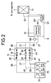
- a sulphonitriding apparatus of the type that supplies a hydrogen sulfide gas from a separate container is depicted in Fig. 2, in which a hydrogen sulfide gas is supplied from a container 70 to the pipe 29 and thence fed into the reaction furnace 21 via the pipe 37.
- the success of sulphurization in the reaction furnace is in itself not dependent on the method by which the hydrogen sulfide gas is supplied.
- the gas sulphonitriding method of the present invention was implemented using an apparatus of the type shown in Fig. 2.
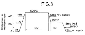
- Fig. 3 is a diagram showing the heating profile adopted in implementing the method of the present invention in Example 1.
- the process started with a stage of heating from ambient temperature, in which an Ar gas was supplied into the reaction furnace 21 chiefly for the purpose of preventing oxidation of the hydraulic piston members in the furnace.
- the valve 38 was opened to supply a hydrogen sulfide (H2S) gas in a predetermined volume (50 ppm).
- H2S hydrogen sulfide
- the valves 45 and 47 were opened to start supplying 20 vol% of ammonia (NH3) for nitriding. Thereafter, the temperature in the reaction furnace was maintained at 500°C for 6 hours to perform nitriding.
- the heating in the reaction furnace was ceased and it was allowed to cool slowly at a rate of 50°C/h.
- the temperature decreased to 400°C the supply of NH3 gas was ceased.
- the concentration of hydrogen sulfide gas was increased to 150 ppm and the temperature of 300°C was maintained for 3 hours.
- the heating in the reaction furnace was ceased.
- the furnace temperature decreased to 200°C the supply of hydrogen sulfide gas was also ceased and the reaction furnace was left to cool to ambient temperature in an Ar gas atmosphere.
- Example 1 The procedure of Example 1 was repeated with the following modifications made: no hydrogen sulfide gas was used and only ammonia gas having a concentration of 20 vol% was supplied together with Ar gas to perform gas nitriding at 500°C for 6 hours; thereafter, the supply of ammonia gas and the heating in the reaction furnace were ceased and the furnace was left to cool to ambient temperature in an Ar gas atmosphere.
- the hydraulic piston members that were gas nitrided in Comparative Example 1 were polished to remove the ⁇ -Fe2 ⁇ 3N layer from the surface.
- the polished members were immersed in a thiocyanate containing salt bath held at 190°C and anodic electrolysis was conducted with the parts connected to anode and the treating vessel to cathode, whereby an iron sulfide layer was formed on the surface layer of each member.
- This sulphurization process is generally called the Caubet process. Sulphurization by the Caubet process is impossible without polishing the gas nitrided hydraulic piston members to remove the surface ⁇ -Fe2 ⁇ 3N layer.
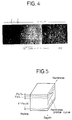
- Example 1 The hydraulic piston members sulphonitrided in Example 1 were examined for their cross-sectional structure with a microscope. The results are shown in Fig. 4, from which one can see that a layer of granular FeS2 crystals formed on the topmost surface of the members, a layer of "streaky” FeS crystals formed beneath, and a layer of acicular ⁇ '-Fe4N crystals formed further beneath.
- Fig. 5 is a characteristic diagram showing schematically the relationship between the cross-sectional structure of the sulphonitrided surface of the hydraulic piston members and its hardness.
- the topmost FeS2 layer has the lowest hardness whereas the highest hardness is attained in an area slightly below the interface between the FeS layer and the ⁇ '-Fe4N layer. The hardness sharply decreases in the deeper area.
- Fig. 6a is a diffraction scan for the first and second sulfide layers
- Fig. 6b is a diffraction scan for the third layer made of a nitride.
- a FeS2 layer was present on the topmost surface of the members treated by the method of the present invention, with a FeS layer lying beneath.
- the scan of Fig. 6a also shows diffraction lines associated with Fe3O4. This oxide would have derived from the water that was produced during the evolution of hydrogen sulfide.
- the FeS2 layer had a thickness of ca. 2 ⁇ m and the underlying FeS layer was ca. 2 ⁇ m thick.
- a ⁇ '-Fe4N layer formed beneath the FeS layer but there was no "white layer” present.
- the ⁇ '-Fe4N layer was ca. 150 ⁇ m thick.
- Fig. 7a shows the compositional distribution of sulfur atoms; the solid line plots the results of analysis on the piston members treated in Example 1 and the dashed line plots the results for the piston members treated in Comparative Example 2.
- Fig. 7b shows the compositional distribution of nitrogen atoms; the solid line plots the results of analysis on the piston members treated in Example 1 and the dashed line plots the results for the piston members treated in Comparative Example 2.
- Fig. 7b very few nitrogen atoms were present on the surface of the piston members treated by the sulphonitriding method of the present invention.
- a fairly large number of nitrogen atoms were present on the surface of the piston members treated by the Caubet process. This fact would suggest that the extremely thin FeS layer formed by the Caubet process is partially interspersed with a nitride.
- Hydraulic piston members were sulphonitrided under identical conditions to those employed in Example 1, except that the period of gas nitriding at 500°C was shortened from 6 to 3 hours.
- Example 1 which were treated by gas nitriding at 500°C for 6 hours and then gas sulphurized at 250°C had hardness values that were substantially comparable to those of the samples that were first gas nitrided, then sulphurized by the Caubet process in the conventional manner.
- Hydraulic piston members were gas sulphonitrided under identical conditions to those employed in Example 1, except that gas nitriding (the primary heat treatment) was performed for 6 hours at 560°C instead of 500°C.
- Hydraulic piston members were gas sulphonitrided under identical conditions to those employed in Comparative Example 3, except that the period of gas nitriding at 560°C was shortened to 3 hours.
- the gas sulphonitriding methods of the present invention are in sharp contrast with the prior art in that they are capable of forming a FeS2 layer on the topmost surface of a steel sliding member. If desired, a FeS layer and a ⁇ '-Fe4N layer can be formed, in that order, beneath the FeS2 layer.
- FeS2 has a weaker binding force and provides a better "fit" between mating parts. Further, FeS2 is capable of retaining twice or three times as much lubricant as can be held by FeS. Hence, in the presence of a FeS2 layer on the topmost surface of a sliding member, it can be brought into engagement with the mating part very smoothly without causing any damage.
- the sliding member of the present invention has on its topmost surface a FeS2 layer that has a good "fit” and a high capability of retaining lubricants.
- a FeS layer that will readily deform under shear stress.
- ⁇ '-Fe4N highly wear-resistant iron nitride
- the method of the present invention permits a sulphurizing gas and a nitriding gas to be supplied, either in admixture or individually, into the reaction surface and, hence, sliding members can be treated to have layers having desired compositions.
Landscapes
- Engineering & Computer Science (AREA)
- Chemical & Material Sciences (AREA)
- General Engineering & Computer Science (AREA)
- Mechanical Engineering (AREA)
- Combustion & Propulsion (AREA)
- Chemical Kinetics & Catalysis (AREA)
- Materials Engineering (AREA)
- Metallurgy (AREA)
- Organic Chemistry (AREA)
- Solid-Phase Diffusion Into Metallic Material Surfaces (AREA)
Description
- This invention relates to a method of modifying and otherwise treating the surfaces of rotating, sliding and rocking members such as pistons, cylinders and valves that are used in hydraulic pumps and motors in construction equipment. More particularly, this invention relates to steel sliding members improved in low-friction property and high wear-resisting (anti-seizure) characteristics, as well as to a process for producing such steel sliding members.
- While many processes of metal surface treatment have been proposed for improving the wear resistance, fatigue resistance, lubrication and anti-seizure characteristics of steel members, sulphonitriding is especially suited to the purpose of improving the sliding characteristics of metals in a "boundary lubrication region" where the sliding condition is so hostile as to potentially cause a local direct contact of two metal parts if the lubricant film is broken.
- Sulphonitriding is commonly performed by a "mixed salt bath" method using neutral or reducing salt baths added with sulfur compounds. However, the cyanides or cyanates in the salt baths are prone to degradation or deterioration at elevated temperatures and it is difficult to maintain a uniform salt bath composition for an extended time. Further, the use of very poisonous cyanides is not desirable from the viewpoint of preventing pollutions. The difficulty in controlling the bath concentration makes it difficult to treat many types of steel materials with appropriate layers. Further, the liquid bath components sometimes fail to reach every portion of the steel member being treated and there is a high possibility that some portions remain untreated.
- A gas sulphonitriding process has been proposed with a view to solving the aforementioned problems of the mixed salt bath method. According to gas sulphonitriding, steel members of any complex shapes can be sulphonitrided almost completely and few or no portions of the steel member remain untreated. However, an ε-Fe₂₋₃N layer (usually called a "white layer") will form if the surface treatment is conducted by the conventional gas sulphonitriding process. This ε-Fe₂₋₃N layer has a hard and brittle mechanical property and has been unable to achieve satisfactory improvements in the wear resistance of steel members.
- JP-A-55 011 107 describes a method, in which a steel member is heated to 500°C in an atmosphere containing nitriding and sulphurizing gases to form reaction layers of FeS and mixed sulfide and nitrides of iron on the surface of the member.
- GB-A-1 460 073 discloses a gas sulphonitriding apparatus having a reaction furnace for performing gas sulphurizing and nitriding treatments. By means of the system of valves surrounding the sulphur-evaporator, this apparatus is capable of supplying sulphurizing and nitriding gases either simultaneously or separately. The sulphurizing gas is supplied from a separate container.
- The present invention has been accomplished under these circumstances and has as a principal object providing a steel sliding member having a novel sulphonitrided film structure.
- Another object of the present invention is to provide a novel gas sulphonitriding method that is capable of forming appropriate treated layers on many types of steel members.
- To achieve its principal object, the present invention provides a sliding member that contains Fe as a matrix and which has on the topmost surface a layer consisting essentially of FeS₂ that is formed as a result of binding with the matrix Fe. This sliding member is preferably made of steels, with a FeS layer and a γ'-Fe₄N layer being formed in that order below the FeS₂ layer on the topmost surface.
-
- Fig. 1 is a schematic diagram showing a layout for a sulphonitriding apparatus of the type that supplies an in situ generated hydrogen sulfide gas for a gas sulphonitriding method;
- Fig. 2 is a schematic diagram showing a layout for a sulphonitriding apparatus of the type that supplies a hydrogen sulfide gas from a separate container for implementing the gas sulphonitriding method of the present invention.
- Fig. 3 is a diagram showing the heating profile adopted in implementing another version of the gas sulphonitriding method of the present invention in Example 1;
- Fig. 4 is an optical micrograph showing a cross-sectional structure of the hydraulic piston member treated in Example 1;
- Fig. 5 is a characteristic diagram showing the hardness profile in depth direction of a cross-sectional structure of the hydraulic piston member treated in Example 1;
- Figs. 6a, 6b, 6c and 6d are graphs showing the results of elemental analysis performed by Auger electon spectroscopy on the surfaces of hydraulic piston members as treated in Example 1 and Comparative Examples 1 and 2;
- Figs. 7a and 7b are characteristic diagrams showing the compositional distributions of sulfur and nitrogen atoms, respectively, in the surfaces of hydraulic piston members as treated in Example 1 and Comparative Example 2;
- Fig. 8 is a characteristic diagram showing the results of depth analysis for Vickers hardness profile in the hydraulic piston members treated in Examples 1 and 2 and in Comparative Example 2;
- Fig. 9 is an optical micrograph showing a cross-sectional structure of the hydraulic piston member treated in Comparative Example 3; and
- Fig. 10 is a characteristic diagram showing the results of depth analysis for Vickers hardness profile in the hydraulic piston members treated in Comparative Examples 3 and 4.
- The method of forming a FeS₂ layer on the topmost surface of a steel member consists typically of supplying a predetermined concentration of a sulphurizing gas together with a nitriding gas at a concentration of 10 - 70 vol-% and a carrier gas into a reaction furnace containing the steel member to be treated, performing a primary heat treatment at a temperature within the range of 450 - 540°C, then ceasing the supply of the nitriding gas, slowly reducing the temperature in the reaction furnace to a level in the range of 200 - 350°C, and performing a secondary heat treatment at that temperature. In this method, the sulphurizing gas may be admitted into the reaction furnace together with the carrier gas before the nitriding gas is supplied to perform the primary heat treatment.
- Stated more specifically, the nitriding gas is an ammonia gas and the sulphurizing gas is a hydrogen sulfide gas which is supplied at a concentration of 50 - 200 ppm, preferably 100 - 180 ppm, more preferably 160 - 170 ppm, most preferably 150 ppm, together with a carrier gas and an ammonia gas at a concentration of 10 - 70 vol%, preferably 20 - 50 vol%, most preferably 20 vol%, into the reaction furnace containing the steel member to be treated, and the primary heat treatment is performed at a temperature in the range of 450 - 540°C, preferably 480 - 530°C, most preferably 500 - 520°C and, after the supply of the ammonia gas is ceased, the reaction furnace is gradually cooled to a temperature in the range of 200 - 350°C, preferably 230 - 280°C, most preferably to 250°C, at which temperature the secondary heat treatment is conducted.
- In this method, a hydrogen sulfide gas may be supplied from a separate container or it may be supplied after in situ generation. For in situ generation, a sulphur-containing inorganic compound selected from the group consisting of metal sulfides and ammonium sulfide may be reacted with a dilute mineral acid having a concentration of 5 - 30 wt% that is selected from the group consisting of hydrochloric acid, nitric acid, an alcoholic solution of hydrochloric acid, and an aqueous solution of nitric acid.
- The method described above can be implemented with the gas sulphonitriding apparatus which is adapted to supply the sulphurizing and nitriding gases either simultaneously or separately into the reaction furnace. If the sulphurizing gas is first introduced into the reaction furnace together with the carrier gas, with the nitriding gas being subsequently introduced for heat treatment, a sulfide layer will be first formed to retard the diffusion of nitrogen and, as a result, the formation of a nitride layer (in particular, the "white layer") is effectively inhibited to provide a satisfactory result.
- The gas sulphonitriding apparatus may be adapted to perform only sulphurization on steel members. In a typical method of this sulphurization, a hydrogen sulfide gas is introduced at a concentration within the range of 50 - 200 ppm, preferably 100 - 180 ppm, more preferably 160 - 170 ppm, most preferably at 150 ppm, together with a carrier gas into a reaction furnace containing the steel member to be treated, and the steel member is heat treated at a temperature in the range of 200 - 350°C, preferably 230 - 280°C, most preferably at 250°C.
- The surface of the steel member to be treated is preferably grained to a roughness within the range of 1.0 - 20 µm by providing straight grooves, crossed grooves, random grooves, dimples or other types of small recesses in the surface of the steel member which is to be treated.
- As will be apparent from the foregoing description, the most characteristic feature of the steel sliding member of the present invention is that it has a FeS₂ layer on the topmost surface. No such steel sliding members having a FeS₂ layer on the topmost surface can be obtained by the prior art sulphonitriding methods. For example, Journal of the Japan Institute of Metals, vol. 51, No. 10, pp. 930 - 934 (1987) discloses a method in which an iron piece is sulphonitrided with 150 ppm of hydrogen sulfide and 75 vol% ammonia at a temperature of 853 K for a time period of 3.6 - 21.6 ks. An X-ray diffraction analysis of a cross-sectional structure of the sample obtained revealed the presence of FeS on the topmost surface but no FeS₂ layer was found to have formed.
- Similarly, the sulphonitriding methods disclosed in Unexamined Published Japanese Patent Application Nos. 11107/1980 and 39155/1985 only form a FeS layer on the topmost layer.
- JP-A-58 091 166 discloses a method of sulphurizing cast iron which comprises immersing a cast iron material in an aqueous solution of nitric acid and thereafter bringing it into contact with a gaseous sulfur vapor atmosphere, thereby forming a sulphurized layer on the surface of said material. According to this method, the surface of the cast iron changes to a sulfide chiefly made of iron sulfides (FeS and FeS₂) but FeS and FeS₂ will be formed as a mixture and do not form a structure that consists of as clearly separate layers as in the case of the present invention.
- If, in the prior art gas sulphonitriding process, a sulphurizing gas (e.g. hydrogen sulfide gas) and a nitriding gas (e.g. ammonia gas) are mixed and supplied simultaneously into a reaction furnace for performing sulphonitriding under heating, a FeS (iron sulfide) layer, an ε-Fe₂₋₃N layer (usually called a "white layer") and a γ'-Fe₄N layer will form in the cross-sectional structure. However, in gas sulphonitriding which utilizes the simultaneous diffusion of sulfur and nitrogen atoms, the formation of the respective layers is dependent on the diffusion coefficients of N and S atoms in the matrix (e.g. steel). Hence, gas sulphonitriding has a tendency to form preferentially an ε-Fe₂₋₃N (also called a "white layer") on the surface of the matrix during the nitriding reaction. This ε-Fe₂₋₃N layer is hard and has a brittle mechanical property. If members having this "white layer" on the topmost surface are used as hydraulic members for construction equipment, particulary in rotating or sliding members such as those of hydraulic pumps or motors where strong impact is exerted, abnormal friction such as seizure or "galling" that would be ascribable to the "shedding off" of the "white layer" occurs during rotation or sliding.
- The present inventors conducted extensive research and experimental work for many years in order to solve the aforementioned problems associated with the process of sulphonitriding steel members with ammonia and hydrogen sulfide gases and found that when a hydrogen sulfide gas at a concentration in the range of 10 - 500 ppm and ammonia gas at a concentration of 10 - 70 vol-% were introduced into a reaction furnace together with a carrier gas, followed by primary heat treatment at a temperature within the range of 450 - 540°C, and the primary heat treatment for sulphonitriding with the mixture of sulphurizing and nitriding gases was followed by the supply of only the sulphurizing gas into the reaction furnace to perform a secondary heat treatment for sulphurization for a predetermined time at a temperature of 200 - 350°C which was lower than the temperature adopted in the primary heat treatment, a thick and stable FeS₂ layer was formed on the topmost surface of the matrix.
- The exact mechanism behind the sulphonitriding process of the present invention has not been fully unravelled and is still at the stage of speculation. However, it could at least be said that although FeS₂ is formed in the primary heat treatment for sulphonitriding, it would be decomposed into FeS and S at 450 - 500°C within the temperature range for the primary heat treatment. In the primary heat treatment, the resulting FeS and S would retard the diffusion of nitrogen atoms, thereby inhibiting the formation of a "white layer". In the cooling process subsequent to the primary heat treatment, FeS₂ would be regenerated on the topmost surface of the member being treated. Therefore, by performing the secondary heat treatment for a predetermined time at 200 - 350°C which is lower than the temperature adopted for the primary heat treatment, a FeS₂ layer of adequate thickness would be formed.
- The layer of FeS crystals forms streaks whereas the layer of FeS₂ crystals consists of grains. Therefore, FeS₂ has a weaker binding force and provides a better "fit" between mating parts. Further, FeS₂ is capable of retaining twice to three times as much lubricant as can be held by FeS. Hence, in the presence of a FeS₂ layer on the topmost surface of a sliding member, it can be brought into engagement with the mating part very smoothly without causing any damage.
- The sliding member of the present invention has on its topmost surface a FeS₂ layer that has a good "fit" and a high capability of retaining lubricants. Below the FeS₂ layer is a FeS layer that will readily deform under shear stress. Situated next below is a highly wear-resistant iron nitride (γ'-Fe₄N) layer. With this arrangement, the destruction of lubricant films due to tiny asperities that are created due to working tolerances and/or working processes, in particular, the occurrence of undesired phenomena such as "galling" or seizure that due to contact between projections can be significantly reduced by the inherent nature of the FeS₂ layer and the underlying FeS layer. These two layers combine together to provide a synergistic lubricating action that imparts an adequate "fit" to frictional surfaces, whereby excellent tribological characteristics are insured for sliding members of interest.
- For implementing the sulphonitriding method of the present invention, the primary heat treatment for sulphonitriding is performed at a temperature within the range of 450 - 540°C and the secondary heat treatment for sulphurization is performed at a temperature within the range of 200 - 350°C. If the temperature for the primary heat treatment exceeds 540°C, a white layer (ε-Fe₂₋₃N layer) will form preferentially, which is undesirable for the purposes of the present invention. Below 450°C, the nitriding reaction will proceed so slowly that at least 50 hours is necessary to complete the primary heat treatment. If the temperature for the secondary heat treatment is less than 200°C, the formation of a stable FeS₂ (marcasite) layer takes too much time to make the process industrially infeasible. Beyond 350°C, undesired transformation to instable FeS₂ crystals (pyrite) can occur.
- After the end of the primary heat treatment for sulphonitriding, the process makes a transition to the secondary heat treatment for sulphurization, with the temperature being lowered from the one adopted for the primary heat treatment to the one suitable for the secondary heat treat- ment. The rate of temperature lowering is preferably no faster than 50°C/h. If the temperature is lowered at a rate exceeding 50°C/h, the adhesion to the underlying FeS layer will decrease to make it difficult to form a stable FeS₂ layer.
- The time required to perform the primary heat treatment for sulphonitriding is not in itself critical to the accomplishment of the present invention. The time of the primary heat treatment is variable with factors such as the heating temperature and the concentrations of supplied gases but it is generally within the range of several hours to several tens of hours. If the temperature for the primary heat treatment is 500 - 520°C, the heating time usually ranges from 3 to 6 hours and is about 20 hours at the longest.
- Similarly, the time required for the secondary heat treatment for sulphurization also is not critical to the accomplishment of the present invention. The time of the secondary heat treatment is generally within the range of several hours to several tens of hours. If the temperature for the secondary heat treatment is 250°C, the heating time is about 3 hours.
- The concentration of the hydrogen sulfide gas used in the gas sulphonitriding method of the present invention is in the range of 50 - 200 ppm, preferably ca. 100 - 180 ppm. Because of this low concentration, any leakage of the hydrogen sulfide gas is not likely to cause a serious accident. If the concentration of the hydrogen sulfide gas is less than 50 ppm, a very long time is required to form a satisfactory sulphurized layer. As regards the formation of a sulphurized layer, the best result is obtained when the concentration of the hydrogen sulfide gas is ca. 160 - 170 ppm. Therefore, even if the hydrogen sulfide gas is used at concentrations higher than 200 ppm, its effectiveness for the formation of a sulphurized layer is already saturated and only diseconomy will result. Further, the potential hazard of a leaking hydogen sulfide gas will increase. As a matter of fact, it is quite surprising and novel that a satisfactory sulphurized layer can be formed within a short time of gas sulphonitriding using a hydrogen sulfide gas at comparatively low concentrations in the range of ca. 50 - 200 ppm.
- The concentration of the ammonia gas used in the gas sulphonitriding method of the present invention is in the range of 10 - 70 vol%. Below 10 vol%, not only is the time of nitriding process prolonged considerably but it is also impossible to form a nitrided layer having adequate hardness. Beyond 70 vol%, more nitrided layer will form than a sulphurized layer and the excessive initial hardness of the treated part not only makes it difficult to achieve smooth engagement with the mating part but also increases the chance of "galling".
- In accordance with the present invention, only sulphurization may be performed independently to form a sulfide layer on the surface of a steel member. For example, a sulfide layer may formed on the surface of a member that has already been provided with a nitride layer by another method or, alternatively, only a sulfide layer may be formed on the surface of an untreated matrix. For performing only sulphurization in an independent manner, the process conditions may be the same as those employed for achieving sulphurization in the already-described sulphonitriding process.
- The steel members that can be treated by the method of the present invention are iron-based metal members that are subjected to sliding contact in various applications such as machines, apparatus and equipment.
- As described in Journal of the Japan Institute of Metals, supra, vol. 51, No. 10, pp. 930 - 931 (1987), preliminary polishing has been a common practice for steel piece that need be surface-treated by the conventional sulphonitriding process. However, according to the study of the present inventors, steel sliding members that were sulphonitrided after surface polishing had only poor wear resistance and that they were found to cause abnormal friction such as "galling" within a short time of sliding.
- Under the circumstances, the present inventors grained the surfaces of steel members as workpieces by forming straight grooves, crossed grooves, random grooves, dimples and other kinds of small recesses through appropriate means such machining, etching and laser-assisted processing. In this way, it was insured that the sulphurized layer formed on the surfaces of steel members would not disappear in spite of prolonged frictional sliding, whereby the aforementioned problems of the prior art could be successfully solved. Grooves can be formed by machining or laser-assisted processing whereas a network of dimples and other kinds of small recesses can generally be formed by etching. The roughness of asperities to be formed on the surfaces of steel members is preferably within the range of 1.0 - 20 µm. If the surface roughness is less than 1.0 µm, the asperities are not highly effective in anchoring the sulphurized layer onto the surfaces of steel members. If the surface roughness exceeds 20 µm, undesired phenomena such as seizure will occur on account of a local increase in the planar pressure.
- Embodiments of the present invention are described below more specifically with reference to the accompanying drawings.
- Fig. 1 is a schematic diagram showing a layout for an apparatus that can be used to implement the gas sulphonitriding method of the present invention. The apparatus shown in Fig. 1 is of the type that supplies a hydrogen sulfide gas as generated on the site. The gas sulphonitriding apparatus generally indicated by 1 consists basically of an Ar and NH₃
gas supply unit 3, a gasflow control unit 5, a sulphurizinggas generating unit 7, asulphonitriding unit 9, and acleaning unit 11. - A sulphurizing gas such as a hydrogen sulfide gas can be generated in the sulphurizing
gas generating unit 7 by carrying out an organic or inorganic chemical reaction in athermostatic bath 13. Aglass reaction vessel 15 is accommodated in thethermostatic bath 13 and charged with a metal sulfide such as iron sulfide or a sulfide such as ammonium sulfide through aclosable opening 17. After closing theopening 17, dilute hydrochloric acid, dilute nitric acid, an alcoholic solution of HCl or an alcoholic solution of HNO that have a concentration of 5 - 30 wt% is charged into thereaction vessel 15 through anaddition pipe 19, whereby a hydrogen sulfide gas is generated. - The amount of hydrogen sulfide gas to be evolved can be controlled by various factors including the particle size and amount of the inorganic sulfide to be charged into the reaction vessel, the concentration and amount of dilute mineral acid supplied, and the temperature of the reaction mixture in solution. In order to insure that a hydrogen sulfide gas is evolved in a small amount over a prolonged time, the particle size of the sulfide must be increased whereas the acid concentration and the temperature of the reaction mixture are reduced. Conversely, in order to have a large amount of the hydrogen sulfide gas evolved in a short time, the particle size of the sulfide may be reduced whereas the acid concentration and the temperature of the reaction mixture are increased.
- The total amount of hydrogen gas evolved is determined by the amounts of the inorganic sulfide and dilute mineral acid charged into the reaction vessel. If the amount of hydrogen sulfide necessary to perform sulphurization is already known, the amounts of the inorganic sulfide and dilute mineral acid necessary to evolve that amount of hydrogen sulfides gas can be calculated on a stoichiometric basis. If stoichiometric amounts of the inorganic sulfide and dilute mineral acid are charged into the reaction vessel, no excess hydrogen sulfide gas will evolve and the potential hazard of gas leakage as well as the possible corrosion of equipment by excess gas can be reduced significantly. The amount of hydrogen sulfide gas to be evolved can also be controlled continuously by adjusting the temperature in the
thermostatic bath 13. For example, once hydrogen sulfide gas has been evolved for the time necessary to perform sulphonitriding, the amount of evolution of that gas can subsequently be reduced to zero by properly controlling the temperature in thethermostatic bath 13. - A hydrogen sulfide gas can also be generated by an organic chemical reaction. However, for various reasons such as the ease of gas generation, the ease of controlling the amount of gas evolution, and the cost of gas generation, the adoption of an inorganic chemical approach involving the reaction between a metal sulfide and a dilute mineral acid is preferred.
- In order to prevent the contamination of the inner surface of the
reaction furnace 21, the interior of thefurnace 21 is heated to a predetermined temperature in the range of 500 - 600°C while a vacuum is created within thefurnace 21 by means of a vacuum pump so that oxygen and other unwanted gases that can contaminate the inner surface of the furnace 21 (i.e., the gases that are evolved from the deposit on the wall of the furnace) are discharged. In a preferred embodiment, an Ar gas is supplied from theunit 25 into thereaction furnace 21 via apipe 27 and only after a clean atmosphere is created in thefurnace 21 by purging with the Ar gas, a workpiece having one of the surface configurations described above is introduced into the furnace for performing the intended sulphonitriding process. - The gas sulphonitriding apparatus depicted in Fig. 1 which is to be used in implementing the method of the present invention is operated in the following manner.
- The case of performing sulphurization and nitriding simultaneously in the
reaction furnace 21 is first described. The process starts with generating a hydrogen sulfide gas in thereaction vessel 15 in the manner already described above. In order to dilute the generated hydrogen sulfide gas to a given concentration and to transport the diluted hydrogen sulfide gas to thereaction furnace 21, an Ar gas is supplied into the reaction vessel via apipe 29. Amass flow controller 31 for controlling the flow of Ar gas is provided halfway of thepipe 29. Checkvalves massflow controller 31. By opening or closing these valves, the Ar gas can be supplied into thereaction vessel 15 in a controlled amount. Apipe 37 is connected to thereaction vessel 15 and avalve 38 is provided halfway of saidpipe 37. When the Ar gas is supplied into thereaction vessel 15 through thepipe 29, with thevalve 38 being opened, the evolved hydrogen sulfide gas collecting in the reaction vessel is carried with the Ar gas to be ejected from the vessel and thence sent at a predetermined concentration to thereaction furnace 21 via thepipe 37. - As NH₃
gas supply pipe 39 is connected halfway of thepipe 37. The foremost end of thepipe 39 is connected to an NH₃gas supply source 41. Amass flow controller 43 for controlling the flow of NH₃ gas is provided halfway of thepipe 39. Checkvalves mass flow controller 43. By opening or closing those valves, an NH₃ gas can be supplied in a controlled amount. - The
pipe 27 through which Ar gas is supplied directly into thereaction furnace 21 is also connected to the hydrogen sulfidegas supply pipe 37. Bothpipes gas supply source 25 via amain pipe 49. Amass flow controller 51 for controlling the flow of Ar gas is provided halfway of thepipe 27. Checkvalves mass flow controller 51. By opening or closing those valves, the Ar gas can be supplied in a controlled amount. - If a
valve 60 between avacuum pump 23 and thereaction furnace 21 is closed whereas all the valves present between thevalve 38 and the gasflow adjusting unit 5 are opened, the hydrogen sulfide gas diluted and carried with the Ar gas as supplied through thepipe 37, the NH₃ gas as supplied through thepipe 39 and the dilutent and carrier Ar gas as supplied through thepipe 27 combine within thepipe 37 at a point just ahead of the reaction furnace and the mixture of those gases is fed into thereaction furnace 21 to initiate the intended sulphonitriding process. After performing the sulphonitriding for a period, all of the valves in the gas supply system are closed whereas thevalve 60 is opened and thevacuum pump 23 is run so that the residual hydrogen sulfide and NH₃ gases in thereacion furnace 21 are sent to thecleaning unit 11 via apipe 57. Thecleaning unit 11 is packed with a chemical (e.g. activated carbon) for removing the toxic hydrogen sulfide gas, as well as the noxious NH₃ gas. These harmful gases are immobilized by the chemical and their concentrations are reduced to levels permitted by regulations against pollution. The gas rendered intoxic in this way is discharged into the ambient air. Chemicals other than activated carbon that can be used to remove hydrogen sulfide and NH₃ gases are well known to one skilled in the art. Apressure gage 59 is preferably provided on thepipe 37 at a point just ahead of thereaction furnace 21. - In the gas sulphonitriding apparatus shown in Fig. 1, the
pipe 37 for supplying a hydrogen sulfide gas and thepipe 39 for supplying an NH₃ gas are provided separately, so if thevalves reaction furnace 21. This permits only sulphurization to be performed in a selective or secondary manner. - Alternatively, the temperature in the
thermostatic bath 13 may be controlled or thevalve 38 is closed to cease the supply of the hydrogen sulfide gas permitting only NH₃ and Ar gases to be supplied into the reaction furnace. By adopting either method, only the nitriding treatment can be implemented in a selective manner. - An apparatus of the type that supplies a hydrogen sulfide gas as generated in situ may be suitable for small-scale treatment but it sometimes fails to suit the purpose in large-scale operations. Hence, a hydrogen sulfide gas is preferably supplied from a separate container in order to perform sulphonitriding on a large scale. Needless to say, the method of supplying a hydrogen sulfide gas from a separate container is also applicable to small-scale operations.
- A sulphonitriding apparatus of the type that supplies a hydrogen sulfide gas from a separate container is depicted in Fig. 2, in which a hydrogen sulfide gas is supplied from a
container 70 to thepipe 29 and thence fed into thereaction furnace 21 via thepipe 37. The success of sulphurization in the reaction furnace is in itself not dependent on the method by which the hydrogen sulfide gas is supplied. - The following examples are provided for the purpose of further illustrating the gas sulphonitriding method of the present invention but should in no way be taken as limiting.
- The gas sulphonitriding method of the present invention was implemented using an apparatus of the type shown in Fig. 2.
- Fig. 3 is a diagram showing the heating profile adopted in implementing the method of the present invention in Example 1.
- As shown in Fig. 3, the process started with a stage of heating from ambient temperature, in which an Ar gas was supplied into the
reaction furnace 21 chiefly for the purpose of preventing oxidation of the hydraulic piston members in the furnace. When the temperature in thefurnace 21 reached 200°C, thevalve 38 was opened to supply a hydrogen sulfide (H₂S) gas in a predetermined volume (50 ppm). When the temperature in the reaction furnace reached 400°C, thevalves - After the end of the treatment, all valves were closed and the temperature in the thermostatic bath was lowered to 263 K, whereby the evolution of hydrogen sulfide gas was ceased. Thereafter, the residual hydrogen sulfide and NH₃ gases were forced out of the reaction furnace into the
cleaning unit 11. After the concentration of the residual H₂S gas in the reaction furnace was verified to be lower than a permissible level, the furnace was opened and the treated hydraulic piston members were recovered. - The procedure of Example 1 was repeated with the following modifications made: no hydrogen sulfide gas was used and only ammonia gas having a concentration of 20 vol% was supplied together with Ar gas to perform gas nitriding at 500°C for 6 hours; thereafter, the supply of ammonia gas and the heating in the reaction furnace were ceased and the furnace was left to cool to ambient temperature in an Ar gas atmosphere.
- The hydraulic piston members that were gas nitrided in Comparative Example 1 were polished to remove the ε-Fe₂₋₃N layer from the surface. The polished members were immersed in a thiocyanate containing salt bath held at 190°C and anodic electrolysis was conducted with the parts connected to anode and the treating vessel to cathode, whereby an iron sulfide layer was formed on the surface layer of each member. This sulphurization process is generally called the Caubet process. Sulphurization by the Caubet process is impossible without polishing the gas nitrided hydraulic piston members to remove the surface ε-Fe₂₋₃N layer.
- The hydraulic piston members sulphonitrided in Example 1 were examined for their cross-sectional structure with a microscope. The results are shown in Fig. 4, from which one can see that a layer of granular FeS₂ crystals formed on the topmost surface of the members, a layer of "streaky" FeS crystals formed beneath, and a layer of acicular γ'-Fe₄N crystals formed further beneath.
- Fig. 5 is a characteristic diagram showing schematically the relationship between the cross-sectional structure of the sulphonitrided surface of the hydraulic piston members and its hardness. The topmost FeS₂ layer has the lowest hardness whereas the highest hardness is attained in an area slightly below the interface between the FeS layer and the γ'-Fe₄N layer. The hardness sharply decreases in the deeper area.
- The members treated in Example 1 were cut by successive depths into the interior and the individual cut planes were analyzed by X-ray diffraction (Cu-Kα, 40 kV, 30 mA). The results are shown in Fig. 6. Fig. 6a is a diffraction scan for the first and second sulfide layers, and Fig. 6b is a diffraction scan for the third layer made of a nitride. As is clear from Fig. 6a, a FeS₂ layer was present on the topmost surface of the members treated by the method of the present invention, with a FeS layer lying beneath. The scan of Fig. 6a also shows diffraction lines associated with Fe₃O₄. This oxide would have derived from the water that was produced during the evolution of hydrogen sulfide. The FeS₂ layer had a thickness of ca. 2 µm and the underlying FeS layer was ca. 2 µm thick.
- As is clear from Fig. 6b, a γ'-Fe₄N layer formed beneath the FeS layer but there was no "white layer" present. The γ'-Fe₄N layer was ca. 150 µm thick.
- The members treated in Comparative Examples 1 and 2 were analyzed by X-ray diffraction under the same conditions as mentioned above, and the results are shown in Figs. 6c and 6d. As is clear from Fig. 6c, a white layer was present on the surface of the gas nitrided members. As is clear from Fig. 6d, only a FeS layer could be formed on the surface when sulphurization was performed by Caubet process. A further disadvantages of the Caubet process is the necessity of first performing gas nitriding and then polishing the surface to remove the "white layer". This involves a total of three steps and results in a very low process efficiency.
- The hydraulic piston members sulphonitrided in Example 1 and those which were gas nitrided and sulphurized electrolytically by the Caubet process in Comparative Example 2 were analyzed by Auger electron spectroscopy for the compositional distri- butions of sulfur and nitrogen atoms. The results are shown in Figs. 7a and 7b.
- Fig. 7a shows the compositional distribution of sulfur atoms; the solid line plots the results of analysis on the piston members treated in Example 1 and the dashed line plots the results for the piston members treated in Comparative Example 2. As is clear from Fig. 7a, an extremely large number of sulphur atoms and, hence, sulfides such as FeS₂ and FeS could be introduced into the surface of piston members by the sulphonitriding method of the present invention. On the other hand, only a small number of sulfur atoms could be introduced by the Caubet process; namely, no FeS₂ layer could be formed on the surface of piston members by the Caubet process.
- Fig. 7b shows the compositional distribution of nitrogen atoms; the solid line plots the results of analysis on the piston members treated in Example 1 and the dashed line plots the results for the piston members treated in Comparative Example 2. As is clear from Fig. 7b, very few nitrogen atoms were present on the surface of the piston members treated by the sulphonitriding method of the present invention. On the other hand, a fairly large number of nitrogen atoms were present on the surface of the piston members treated by the Caubet process. This fact would suggest that the extremely thin FeS layer formed by the Caubet process is partially interspersed with a nitride.
- Hydraulic piston members were sulphonitrided under identical conditions to those employed in Example 1, except that the period of gas nitriding at 500°C was shortened from 6 to 3 hours.
- The samples obtained in Examples 1 and 2 and Comparative Example 2 were subjected to a Vickers hardness test and the results are shown in Fig. 8, in which the dashed line refers to the samples of Comparative Example 2, the unfilled circles (o) refer to the samples of Example 1, and the filled circles (●) refer to the samples of Example 2.
- As is clear from Fig. 8, the samples of Example 1 which were treated by gas nitriding at 500°C for 6 hours and then gas sulphurized at 250°C had hardness values that were substantially comparable to those of the samples that were first gas nitrided, then sulphurized by the Caubet process in the conventional manner. The samples of Example 2 which were treated by gas nitriding at 500°C for 3 hours also had commercially acceptable values of Vickers hardness.
- Hydraulic piston members were gas sulphonitrided under identical conditions to those employed in Example 1, except that gas nitriding (the primary heat treatment) was performed for 6 hours at 560°C instead of 500°C.
- Hydraulic piston members were gas sulphonitrided under identical conditions to those employed in Comparative Example 3, except that the period of gas nitriding at 560°C was shortened to 3 hours.
- The piston members treated in Comparative Example 3 were examined for their cross-sectional structure with an optical microscope and the result is shown in the micrograph of Fig. 9. When gas nitriding was performed at 560°C for 6 hours, a FeS₂ layer formed on the topmost surface of each piston member; at the same time, a white ε-Fe₂₋₃N layer also formed between the underlying FeS and γ'-Fe₄N layers.
- The samples of Comparative Examples 3 and 4 were subjected to a Vickers hardness test and the results are shown in Fig. 10, wherein unfilled circles (o) refer to the samples of Comparative Example 3 and filled circles (●) refer to the samples of Comparative Example 4.
- As is clear from Fig. 10, the samples treated by gas nitriding at 560°C had a "white layer" formed in the vicinity of the surface, so the hardness of the topmost surface was unduly high. In fact, as is clear from comparison with the hardness curves shown in Fig. 8 for the case of gas nitriding at 500°C, the initial hardness of the samples increased by a factor of ca. 1.5.
- As discussed on the foregoing pages, the gas sulphonitriding methods of the present invention are in sharp contrast with the prior art in that they are capable of forming a FeS₂ layer on the topmost surface of a steel sliding member. If desired, a FeS layer and a γ'-Fe₄N layer can be formed, in that order, beneath the FeS₂ layer.
- The layer of FeS crystals forms streaks whereas the layer of FeS₂ crystals consists of grains. Therefore, FeS₂ has a weaker binding force and provides a better "fit" between mating parts. Further, FeS₂ is capable of retaining twice or three times as much lubricant as can be held by FeS. Hence, in the presence of a FeS₂ layer on the topmost surface of a sliding member, it can be brought into engagement with the mating part very smoothly without causing any damage.
- The sliding member of the present invention has on its topmost surface a FeS₂ layer that has a good "fit" and a high capability of retaining lubricants. Below the FeS₂ layer is a FeS layer that will readily deform under shear stress. Situated next below is a highly wear-resistant iron nitride (γ'-Fe₄N) layer. With this arrangement, the destruction of lubricant films due to tiny asperities that are created due to working tolerances and/or working processes, in particular, the occurrence of undesired phenomena such as "galling" or seizure due to contact between projections can be significantly reduced by the inherent nature of the FeS₂ layer and the underlying FeS layer. These two layers combine together to provide a synergistic lubricanting action that imparts an adequate "fit" to frictional surfaces, whereby excellent tribological characteristics are insured for sliding members of interest.
- Further, the method of the present invention permits a sulphurizing gas and a nitriding gas to be supplied, either in admixture or individually, into the reaction surface and, hence, sliding members can be treated to have layers having desired compositions.
Claims (16)
- A sliding member that contains Fe as a matrix and which has on the topmost surface a layer essentially consisting of FeS₂ that is formed as a result of binding with the matrix Fe.
- A sliding member according to claim 1 has a FeS layer and a γ'-Fe₄N layer formed, in that order, below the FeS₂ layer.
- A sliding member according to claim 1 or 2 which is made of a steel.
- In a gas sulphonitriding method which comprises sulphonitriding a steel member with a sulphurizing gas and a nitriding gas, the improvement which comprises supplying a predetermined concentration of the sulphurizing gas together with a nitriding gas at a concentration of 10 - 70 vol.-% and a carrier gas into a reaction furnace containing the steel member to be treated, performing a primary heat treatment at a temperature in the range of 450 - 540°C, then ceasing the supply of the nitriding gas, slowly reducing the temperature in the reaction furnace to a level in the range of 200 - 350°C, and performing a secondary heat treatment at that temperature.
- A gas sulphonitriding method according to claim 4 wherein the sulphurizing gas is first introduced into the reaction furnace together with the carrier gas during temperature elevation and, after the passage of a predetermined time, the nitriding gas is also introduced into the reaction furnace to perform the primary heat treatment at a temperature in the range of 450 - 540°C and, subsequently, the supply of the nitriding gas is ceased but the carrier gas and the sulphurizing gas are kept introduced into the reaction furnace as it is slowly cooled to a temperature in the range of 200 - 350°C and the secondary heat treatment is performed at that temperature for a predetermined time.
- A gas sulphonitriding method according to claim 4 wherein the nitriding gas is an ammonia gas and the sulphurizing gas is a hydrogen sulfide gas which is supplied at a concentration of 50 - 200 ppm together with the carrier gas and the ammonia gas into the reaction furnace containing the steel member to be treated, and the primary heat treatment is performed at a temperature in the range of 450 - 540°C and, after the supply of the ammonia gas is ceased, the reaction furnace is gradually cooled to a temperature in the range of 200 - 350°C, at which temperature the secondary heat treatment is performed.
- A gas sulphonitriding method according to claim 6 wherein the hydrogen sulfide gas is supplied from a separate container and the carrier gas is a nitrogen gas or an argon gas.
- A gas sulphonitriding method according to claim 6 wherein the hydrogen sulfide gas is generated on the site by reacting an inorganic compound containing sulfur atoms as selected from the group consisting of metal sulfides and ammonium sulfide with a dilute mineral acid having a concentration of 5 - 30 wt% as selected from the group consisting of hydrochloric acid, nitric acid, an alcoholic solution of hydrochloric acid and an aqueous solution of nitric acid, and the carrier gas is a nitrogen gas or an argon gas.
- A gas sulphonitriding method according to claim 6 wherein the hydrogen sulfide gas has a concentration of 100 - 180 ppm, the ammonia gas has a concentration of 20 - 50 vol%, the primary heat treatment is performed at a temperature of 480 - 530°C, and the secondary heat treatment is performed at a temperature of 230 - 280°C.
- A gas sulphonitriding method according to claim 9 wherein the hydrogen sulfide gas has a concentration of 160 - 170 ppm, the primary heat treatment is performed at a temperature of 500 - 520°C, and the secondary heat treatment is performed at a temperature of 250°C.
- A gas sulphonitriding method according to claim 6 wherein the hydrogen sulfide gas has a concentration of 150 ppm, the ammonia gas has a concentration of 20 vol%, the primary heat treatment is performed at a temperature of 500 - 520°C, and the secondary heat treatment is performed at a temperature of 250°C.
- A gas sulphonitriding method according to any one of claims 6 to 11 wherein the steel member is grained to a surface roughness in the range of 1.0 - 20 µm.
- A gas sulphonitriding method according to claim 12 wherein the steel member is grained by providing straight grooves, crossed grooves, random grooves, dimples or other kinds of small recesses in the surface of the steel member to be treated.
- In a gas sulphurization method that comprises sulphurizing a steel member at least with a hydrogen sulfide gas, the improvement wherein said hydrogen sulfide gas is used for sulphurization at a concentration in the range of 50 - 200 ppm and the sulphurizing treatment is performed at a temperature in the range of 200 - 350°C.
- A gas sulphurization method according to claim 14 wherein the hydrogen sulfide gas is used for sulphurization at a concentration in the range of 100 - 180 ppm, preferably 160 - 170 ppm, or 150 ppm,respectively.
- A gas sulphurization method according to claim 14 wherein the sulphurization treatment is performed at a temperature in the range of 230 - 280°C, preferably 250°C.
Applications Claiming Priority (4)
| Application Number | Priority Date | Filing Date | Title |
|---|---|---|---|
| JP178437/90 | 1990-07-05 | ||
| JP17843790 | 1990-07-05 | ||
| JP3086125A JP2607980B2 (en) | 1990-07-05 | 1991-03-26 | Sliding member and gas sulfurizing / nitriding method thereof |
| JP86125/91 | 1991-03-26 |
Publications (2)
| Publication Number | Publication Date |
|---|---|
| EP0464799A1 EP0464799A1 (en) | 1992-01-08 |
| EP0464799B1 true EP0464799B1 (en) | 1995-10-11 |
Family
ID=26427277
Family Applications (1)
| Application Number | Title | Priority Date | Filing Date |
|---|---|---|---|
| EP91111045A Expired - Lifetime EP0464799B1 (en) | 1990-07-05 | 1991-07-03 | Sliding member and method for producing the same by gas sulphonitriding |
Country Status (4)
| Country | Link |
|---|---|
| US (2) | US5187017A (en) |
| EP (1) | EP0464799B1 (en) |
| JP (1) | JP2607980B2 (en) |
| DE (1) | DE69113689T2 (en) |
Families Citing this family (17)
| Publication number | Priority date | Publication date | Assignee | Title |
|---|---|---|---|---|
| CH687880A5 (en) * | 1993-05-27 | 1997-03-14 | Balzers Hochvakuum | A process for the increase of the wear resistance of workpiece surfaces and for this behandetes workpiece. |
| JPH1068049A (en) * | 1995-07-19 | 1998-03-10 | Mitsui Eng & Shipbuild Co Ltd | Wear-resistant steel, cylinder sliding member of internal combustion engine and ring spring |
| TW408212B (en) * | 1996-10-11 | 2000-10-11 | Sanyo Electric Co | Method for treating metal surface, rotary shaft and vane for refrigerant compressor treated by the method, and refrigerant compressor using the same |
| US5869195A (en) * | 1997-01-03 | 1999-02-09 | Exxon Research And Engineering Company | Corrosion resistant carbon steel |
| JPH10196531A (en) * | 1997-01-07 | 1998-07-31 | Zexel Corp | Variable capacity swash plate compressor and surface treatment therefor |
| JP3305972B2 (en) * | 1997-02-03 | 2002-07-24 | 日立金属株式会社 | Warm mold and method for manufacturing the same |
| US6139973A (en) * | 1997-06-04 | 2000-10-31 | Nihon Parkerizing Co., Ltd | Method for forming wear-resistant layer and iron-based material, on which wear-resistant layer is applied |
| US6561322B2 (en) * | 1998-12-03 | 2003-05-13 | Yamaha Hatsudoki Kabushiki Kaisha | Plated wear surface for alloy components and methods of manufacturing the same |
| JP4487340B2 (en) | 1999-07-21 | 2010-06-23 | 日本精工株式会社 | Method for manufacturing rolling bearing cage |
| JP4650706B2 (en) * | 2000-05-08 | 2011-03-16 | 日立金属株式会社 | Tool for hot working and gas nitronitriding method |
| JP2003147646A (en) * | 2001-11-05 | 2003-05-21 | Toyota Industries Corp | Traveler for spinning frame |
| CN100462472C (en) * | 2006-12-22 | 2009-02-18 | 刘洋 | A kind of gas sulfur nitrogen co-infiltration method |
| US7833636B2 (en) * | 2007-06-16 | 2010-11-16 | Mahle International Gmbh | Piston ring with sulphonitriding treatment |
| DE102009007280A1 (en) * | 2009-02-03 | 2010-08-12 | Federal-Mogul Burscheid Gmbh | Cylinder sleeve for use in cylinder block of internal combustion engine, has layer arranged below another layer, directly abutting at latter layer and consisting of iron nitride precipitations and iron sulfide precipitations |
| JP2012067652A (en) * | 2010-09-22 | 2012-04-05 | Kubota Corp | Sealing device of rotary part of engine |
| JP5358545B2 (en) * | 2010-09-27 | 2013-12-04 | 株式会社クボタ | Engine transmission case sealing device |
| CN115355172A (en) * | 2022-08-08 | 2022-11-18 | 珠海格力电器股份有限公司 | Metal surface composite layer structure and its preparation method, parts and compressor |
Family Cites Families (20)
| Publication number | Priority date | Publication date | Assignee | Title |
|---|---|---|---|---|
| GB701685A (en) * | 1952-04-04 | 1953-12-30 | William Warren Triggs | Improvements in or relating to methods of improving iron or steel surfaces |
| FR1057237A (en) * | 1952-05-19 | 1954-03-05 | Partiot Cementation Atel | Surface heat treatment process for ferrous metals |
| JPS5310534B2 (en) * | 1971-12-03 | 1978-04-14 | ||
| GB1460073A (en) * | 1974-01-12 | 1976-12-31 | Politechnika Lodzka | Surface treatment of metals with gases |
| DE2824534A1 (en) * | 1977-06-03 | 1978-12-07 | Hitachi Ltd | METHOD FOR PURIFYING HYDROGEN SULFUR AND AMMONIA CONTAINING HOT GASES |
| JPS5541940A (en) * | 1978-09-20 | 1980-03-25 | Hitachi Ltd | Ion sulphurizing and nitriding method |
| PL126128B1 (en) * | 1980-02-11 | 1983-07-30 | Politechnika Lodzka | Method of cementation of machine elements and cutting tools |
| US4364995A (en) * | 1981-02-04 | 1982-12-21 | Minnesota Mining And Manufacturing Company | Metal/metal oxide coatings |
| JPS5822541A (en) * | 1981-07-31 | 1983-02-09 | セイコーエプソン株式会社 | Switch contact for charging device |
| JPS5839155A (en) * | 1981-09-02 | 1983-03-07 | Nec Corp | Automatic time calling system |
| US4513057A (en) * | 1982-06-10 | 1985-04-23 | Hughes Aircraft Company | Process for forming sulfide layers |
| FR2531458A1 (en) * | 1982-08-04 | 1984-02-10 | Stephanois Rech Mec | PROCESS FOR SURFACE TREATMENT OF FERROUS SURFACES TO IMPROVE THEIR FRICTION QUALITY AND RESISTANCE TO WEAR AND INJURY |
| JPS6039155A (en) * | 1983-08-12 | 1985-02-28 | Tokyo Netsu Shiyori Kogyo Kk | Gas sulfurizing and nitriding method |
| US4738730A (en) * | 1986-02-18 | 1988-04-19 | Lindberg Corporation | Steam sealing for nitrogen treated ferrous part |
| US4820591A (en) * | 1987-05-11 | 1989-04-11 | Exxon Research And Engineering Company | Corrosion resistant article and method of manufacture |
| JP2521982B2 (en) * | 1987-09-30 | 1996-08-07 | 日本鋼管株式会社 | Method for producing vapor grown carbon fiber |
| JPH081184B2 (en) * | 1987-09-30 | 1996-01-10 | 株式会社日立製作所 | Compressor |
| JPH02270958A (en) * | 1989-04-12 | 1990-11-06 | Komatsu Ltd | Two-stage sulfonitriding method and sulfonitrided product |
| JPH0511107A (en) * | 1991-07-01 | 1993-01-19 | Toshiba Corp | Color filter and liquid crystal display |
| JP3484778B2 (en) * | 1994-09-27 | 2004-01-06 | タカタ株式会社 | Passenger airbag device |
-
1991
- 1991-03-26 JP JP3086125A patent/JP2607980B2/en not_active Expired - Fee Related
- 1991-06-27 US US07/722,182 patent/US5187017A/en not_active Expired - Lifetime
- 1991-07-03 DE DE69113689T patent/DE69113689T2/en not_active Expired - Lifetime
- 1991-07-03 EP EP91111045A patent/EP0464799B1/en not_active Expired - Lifetime
-
1992
- 1992-09-30 US US07/953,803 patent/US5290369A/en not_active Expired - Lifetime
Also Published As
| Publication number | Publication date |
|---|---|
| US5187017A (en) | 1993-02-16 |
| JP2607980B2 (en) | 1997-05-07 |
| DE69113689D1 (en) | 1995-11-16 |
| EP0464799A1 (en) | 1992-01-08 |
| DE69113689T2 (en) | 1996-05-15 |
| US5290369A (en) | 1994-03-01 |
| JPH04228557A (en) | 1992-08-18 |
Similar Documents
| Publication | Publication Date | Title |
|---|---|---|
| US5187017A (en) | Sliding member, and method and apparatus for producing the same by gas sulphonitriding | |
| US5141567A (en) | Method of nitriding steel | |
| EP1396553B1 (en) | Producing metal member with enhanced corrosion resistance by salt bath nitriding | |
| US8951402B2 (en) | Ultra-fast boriding of metal surfaces for improved properties | |
| DE69009603T2 (en) | Process for the pretreatment of metallic workpieces and the nitriding hardening of steel. | |
| US9212416B2 (en) | Low temperature carburization under soft vacuum | |
| US5753052A (en) | Method of treating ferrous surfaces subjected to high friction strains | |
| CN1269988C (en) | Method of salt bath nitriding for producing iron member having improved corrosion resistance and iron parts | |
| EP0479409A2 (en) | Austenitic stainless steel screw and a method for manufacturing the same | |
| CN1106454C (en) | Nitrizing for steel | |
| US5228929A (en) | Thermochemical treatment of machinery components for improved corrosion resistance | |
| EP1712658B1 (en) | Method for surface treatment of metal material | |
| CN1054891C (en) | Method of improving the wear and corrosion resistance of ferrous metal parts | |
| US5576066A (en) | Method of improving the wear and corrosion resistance of ferrous metal parts | |
| US20200010946A1 (en) | Ferrous structural component for use in fouling and corrosive environments, and method of making and using a ferrous structural component | |
| KR900007716B1 (en) | Gas Sulfide Nitriding Method | |
| JP4494995B2 (en) | Metal surface treatment method | |
| US20010035232A1 (en) | Method of preventing nitridation or carburization of metals | |
| EP0059803B1 (en) | A process for case hardening steel | |
| US2875095A (en) | Method of producing surface layers resistant to wear | |
| WO1996023908A1 (en) | Wear resistant tribosystem | |
| Maisuradze et al. | Isothermal heat treatment of the low-carbon martensitic steel | |
| JP4921149B2 (en) | Metal nitriding method | |
| JP2001115177A (en) | Sliding member excellent in seizure resistance and method for producing the same | |
| CN120330465A (en) | A method for preparing corrosion-resistant pearlite steel film by ultrasonic rolling combined with liquid deposition |
Legal Events
| Date | Code | Title | Description |
|---|---|---|---|
| PUAI | Public reference made under article 153(3) epc to a published international application that has entered the european phase |
Free format text: ORIGINAL CODE: 0009012 |
|
| AK | Designated contracting states |
Kind code of ref document: A1 Designated state(s): DE FR |
|
| 17P | Request for examination filed |
Effective date: 19920601 |
|
| 17Q | First examination report despatched |
Effective date: 19931110 |
|
| GRAA | (expected) grant |
Free format text: ORIGINAL CODE: 0009210 |
|
| AK | Designated contracting states |
Kind code of ref document: B1 Designated state(s): DE FR |
|
| REF | Corresponds to: |
Ref document number: 69113689 Country of ref document: DE Date of ref document: 19951116 |
|
| ET | Fr: translation filed | ||
| PLBE | No opposition filed within time limit |
Free format text: ORIGINAL CODE: 0009261 |
|
| STAA | Information on the status of an ep patent application or granted ep patent |
Free format text: STATUS: NO OPPOSITION FILED WITHIN TIME LIMIT |
|
| 26N | No opposition filed | ||
| PGFP | Annual fee paid to national office [announced via postgrant information from national office to epo] |
Ref country code: DE Payment date: 20100630 Year of fee payment: 20 Ref country code: FR Payment date: 20100805 Year of fee payment: 20 |
|
| REG | Reference to a national code |
Ref country code: DE Ref legal event code: R071 Ref document number: 69113689 Country of ref document: DE |
|
| REG | Reference to a national code |
Ref country code: DE Ref legal event code: R071 Ref document number: 69113689 Country of ref document: DE |
|
| PG25 | Lapsed in a contracting state [announced via postgrant information from national office to epo] |
Ref country code: DE Free format text: LAPSE BECAUSE OF EXPIRATION OF PROTECTION Effective date: 20110704 |