EP0462954B1 - Ball end mill and throw away insert for such end mill - Google Patents
Ball end mill and throw away insert for such end mill Download PDFInfo
- Publication number
- EP0462954B1 EP0462954B1 EP91850160A EP91850160A EP0462954B1 EP 0462954 B1 EP0462954 B1 EP 0462954B1 EP 91850160 A EP91850160 A EP 91850160A EP 91850160 A EP91850160 A EP 91850160A EP 0462954 B1 EP0462954 B1 EP 0462954B1
- Authority
- EP
- European Patent Office
- Prior art keywords
- cutting edges
- insert
- top face
- inserts
- end mill
- Prior art date
- Legal status (The legal status is an assumption and is not a legal conclusion. Google has not performed a legal analysis and makes no representation as to the accuracy of the status listed.)
- Expired - Lifetime
Links
Images


Classifications
-
- B—PERFORMING OPERATIONS; TRANSPORTING
- B23—MACHINE TOOLS; METAL-WORKING NOT OTHERWISE PROVIDED FOR
- B23C—MILLING
- B23C5/00—Milling-cutters
- B23C5/02—Milling-cutters characterised by the shape of the cutter
- B23C5/10—Shank-type cutters, i.e. with an integral shaft
- B23C5/1009—Ball nose end mills
- B23C5/1027—Ball nose end mills with one or more removable cutting inserts
-
- B—PERFORMING OPERATIONS; TRANSPORTING
- B23—MACHINE TOOLS; METAL-WORKING NOT OTHERWISE PROVIDED FOR
- B23C—MILLING
- B23C5/00—Milling-cutters
- B23C5/16—Milling-cutters characterised by physical features other than shape
- B23C5/20—Milling-cutters characterised by physical features other than shape with removable cutter bits or teeth or cutting inserts
- B23C5/22—Securing arrangements for bits or teeth or cutting inserts
- B23C5/2204—Securing arrangements for bits or teeth or cutting inserts with cutting inserts clamped against the walls of the recess in the cutter body by a clamping member acting upon the wall of a hole in the insert
- B23C5/2208—Securing arrangements for bits or teeth or cutting inserts with cutting inserts clamped against the walls of the recess in the cutter body by a clamping member acting upon the wall of a hole in the insert for plate-like cutting inserts
- B23C5/2213—Securing arrangements for bits or teeth or cutting inserts with cutting inserts clamped against the walls of the recess in the cutter body by a clamping member acting upon the wall of a hole in the insert for plate-like cutting inserts having a special shape
-
- B—PERFORMING OPERATIONS; TRANSPORTING
- B23—MACHINE TOOLS; METAL-WORKING NOT OTHERWISE PROVIDED FOR
- B23C—MILLING
- B23C2200/00—Details of milling cutting inserts
- B23C2200/08—Rake or top surfaces
- B23C2200/083—Rake or top surfaces curved
-
- B—PERFORMING OPERATIONS; TRANSPORTING
- B23—MACHINE TOOLS; METAL-WORKING NOT OTHERWISE PROVIDED FOR
- B23C—MILLING
- B23C2200/00—Details of milling cutting inserts
- B23C2200/08—Rake or top surfaces
- B23C2200/086—Rake or top surfaces with one or more grooves
-
- B—PERFORMING OPERATIONS; TRANSPORTING
- B23—MACHINE TOOLS; METAL-WORKING NOT OTHERWISE PROVIDED FOR
- B23C—MILLING
- B23C2200/00—Details of milling cutting inserts
- B23C2200/12—Side or flank surfaces
- B23C2200/123—Side or flank surfaces curved
-
- B—PERFORMING OPERATIONS; TRANSPORTING
- B23—MACHINE TOOLS; METAL-WORKING NOT OTHERWISE PROVIDED FOR
- B23C—MILLING
- B23C2200/00—Details of milling cutting inserts
- B23C2200/20—Top or side views of the cutting edge
- B23C2200/201—Details of the nose radius and immediately surrounding areas
-
- B—PERFORMING OPERATIONS; TRANSPORTING
- B23—MACHINE TOOLS; METAL-WORKING NOT OTHERWISE PROVIDED FOR
- B23C—MILLING
- B23C2200/00—Details of milling cutting inserts
- B23C2200/20—Top or side views of the cutting edge
- B23C2200/203—Curved cutting edges
-
- B—PERFORMING OPERATIONS; TRANSPORTING
- B23—MACHINE TOOLS; METAL-WORKING NOT OTHERWISE PROVIDED FOR
- B23C—MILLING
- B23C2200/00—Details of milling cutting inserts
- B23C2200/20—Top or side views of the cutting edge
- B23C2200/205—Discontinuous cutting edges
-
- B—PERFORMING OPERATIONS; TRANSPORTING
- B23—MACHINE TOOLS; METAL-WORKING NOT OTHERWISE PROVIDED FOR
- B23C—MILLING
- B23C2200/00—Details of milling cutting inserts
- B23C2200/36—Other features of the milling insert not covered by B23C2200/04 - B23C2200/32
- B23C2200/367—Mounted tangentially, i.e. where the rake face is not the face with largest area
-
- Y—GENERAL TAGGING OF NEW TECHNOLOGICAL DEVELOPMENTS; GENERAL TAGGING OF CROSS-SECTIONAL TECHNOLOGIES SPANNING OVER SEVERAL SECTIONS OF THE IPC; TECHNICAL SUBJECTS COVERED BY FORMER USPC CROSS-REFERENCE ART COLLECTIONS [XRACs] AND DIGESTS
- Y10—TECHNICAL SUBJECTS COVERED BY FORMER USPC
- Y10T—TECHNICAL SUBJECTS COVERED BY FORMER US CLASSIFICATION
- Y10T407/00—Cutters, for shaping
- Y10T407/19—Rotary cutting tool
- Y10T407/1906—Rotary cutting tool including holder [i.e., head] having seat for inserted tool
- Y10T407/1908—Face or end mill
- Y10T407/1924—Specified tool shape
-
- Y—GENERAL TAGGING OF NEW TECHNOLOGICAL DEVELOPMENTS; GENERAL TAGGING OF CROSS-SECTIONAL TECHNOLOGIES SPANNING OVER SEVERAL SECTIONS OF THE IPC; TECHNICAL SUBJECTS COVERED BY FORMER USPC CROSS-REFERENCE ART COLLECTIONS [XRACs] AND DIGESTS
- Y10—TECHNICAL SUBJECTS COVERED BY FORMER USPC
- Y10T—TECHNICAL SUBJECTS COVERED BY FORMER US CLASSIFICATION
- Y10T407/00—Cutters, for shaping
- Y10T407/19—Rotary cutting tool
- Y10T407/1946—Face or end mill
- Y10T407/1948—Face or end mill with cutting edge entirely across end of tool [e.g., router bit, end mill, etc.]
-
- Y—GENERAL TAGGING OF NEW TECHNOLOGICAL DEVELOPMENTS; GENERAL TAGGING OF CROSS-SECTIONAL TECHNOLOGIES SPANNING OVER SEVERAL SECTIONS OF THE IPC; TECHNICAL SUBJECTS COVERED BY FORMER USPC CROSS-REFERENCE ART COLLECTIONS [XRACs] AND DIGESTS
- Y10—TECHNICAL SUBJECTS COVERED BY FORMER USPC
- Y10T—TECHNICAL SUBJECTS COVERED BY FORMER US CLASSIFICATION
- Y10T407/00—Cutters, for shaping
- Y10T407/23—Cutters, for shaping including tool having plural alternatively usable cutting edges
Definitions
- the present invention relates to a ball end mill according to the precharacterising part of claim 1 for the chipforming machining of metal workpieces.
- the end mill comprises a tool body that is rotatable about its longitudinal axis.
- the forward end of the tool body is hemispherically shaped and has several separate pockets for the receipt of indexable inserts.
- One of the inserts is substantially triangular in shape and is mounted tangentially in the mantle surface of the tool body close to its center such that the main cutting edge of the insert is oriented generally radially and has one of its corner portions located at the center of the tool body.
- the invention furthermore relates to a polygonal throw away insert specifically designed for use with such an end mill.
- Such ball nose end mills with indexable inserts are previously known, for instance as disclosed in U.S. Patent No. 4,252,480. That ball nose end mill includes a central insert having a cutting edge of convex shape along a portion of the periphery of one of its side surfaces for the purpose of reducing the thrust forces.
- a basically similar ball end mill with throw away inserts is known from U.S. Patent 4,618,296 representing the closest prior art in which all inserts have a generally triangular shape and are tangentially oriented in the tool body. The convex formation is achieved by making the outermost surface of the insert partially convex in shape.
- the invention relates also to an indexable cutting insert according to the precharacterising part of claim 12.
- each insert of the above-described known ball end mills becomes high and are unfavorably distributed over the tool body. Further, each insert must be active during a long cutting engagement in the workpiece. It would, therefore, be desirable to provide a ball end mill with several inserts that are mounted in an optimal fashion over the mantle surface of the end mill so that a more limited portion of the cutting insert corner comes into engagement with the workpiece at different engagements.
- a ball nose end mill for metalworking comprising a rotary body rotatable about a longitudinal axis thereof, a forward end surface of said body being of generally hemispherical shape and including a plurality of cavities; and a plurality of indexable cutting inserts mounted in respective ones of said cavities; a central one of said inserts being of substantially triangular shape and mounted closely adjacent said longitudinal axis; said central insert including a forwardly facing, substantially triangular top face and a plurality of edge faces intersecting one another to form three corner regions, and intersecting said top face to form therewith a plurality of main cutting edges, each of said main cutting edges being disposed between two of said corner regions and being convexly curved when viewed in a direction toward the respective edge face; said central insert being mounted such that one of said main cutting edges constitutes an active cutting edge positioned in a cutting orientation; one corner region of said central insert being situated at an end of said active cutting edge and is located immediately adjacent said axis, characterized in
- the present invention also relates to an indexable cutting insert which is adapted for use in a ball nose end mill, comprising a substantially flat bottom face on which said insert is to be supported; a generally convexly shaped top face disposed opposite said bottom face; and a plurality of edge faces interconnecting said top and bottom faces, and intersecting said top face at an acuted angle, the intersection of said edge faces with said top face forming a plurality of main cutting edges and a plurality of secondary cutting edges, said secondary cutting edges being located at respective corner regions of said insert and being convexly curved when said top face is viewed in plan, each of said main cutting edges being located between respective pairs of said corner regions and being generally convexly curved as viewed in a direction toward its respective edge face, each of said main cutting edges being straight when said top face is viewed in plan; each of said secondary cutting edges intersecting first and second ones of said main cutting edges at first and second points of intersection, respectively, whereby a first line tangent to said first point of intersection coincides with said first main
- a ball nose end mill has a cylindrical shank 10 rotatable in a direction of cutting CD around a central longitudinal axis 11.
- the shank terminates in a substantially hemispherical cutting face 12 in which there are provided cavities.
- the surface 12 is generated by a radius R' (see FIG. 2).
- the cavities are shaped to receive indexable cutting inserts 13-19 made preferably of cemented carbide.
- a central insert 13, i.e., the insert located close to the longitudinal axis 11, includes a bottom face 20 and a top face 21 (see FIG. 1A).
- the insert 13 is of substantially triangular shape when viewed in plan, i.e., in a direction toward its top face (see FIG. 1).
- the top face 21 is convexly shaped, more specifically is in the general shape of a portion of a sphere so as to generally conform to the profile of the hemispherical face 12 (see FIG. 3). All of the additional inserts 14-19 of this end mill are substantially rectangular in shape and have planar, parallel bottom and top faces.
- top faces of all of the inserts 13-19 are centrally apertured for the receipt of central clamp screws for securing the inserts to the end mill body. That aperture extends completely through the top and bottom faces of the respective insert.
- Each insert includes edge faces (e.g., see the edge faces 22 of the insert 13) which intersect the top face to form cutting edges therewith.
- the central insert 13 has three identical cutting edges 23, 24, 25. Bevels 33, 32 and 31 are situated immediately inwardly of the cutting edges 23, 24, 25, respectively.
- the cutting inserts 13-19 are of positive shape, i.e., each of the edge faces thereof intersects the top face at an acute angle.
- the degree of inclination of the edge faces relative to the top face varies around the insert. More specifically, the inclination of such edge face is greater at the corner regions of the insert than at the intermediate regions of the edge face.
- intermediate region is meant a region of the edge face situated between the corner regions of the insert.
- First and second ones of the additional inserts 16 and 19 have their active cutting edges located on opposite sides of the axis 11 and substantially in a common first radial plane P1 which contains the axis 11 (see FIG. 1).
- a third one of the additional inserts 15 has a convexly curved active cutting edge arranged substantially in a second plane P2 which is different from the first plane and which contains the axis 11.
- Fourth and fifth ones of the inserts 14, 18 have straight main cutting edges arranged substantially in a common plane, e.g., the second plane P2, which is oriented substantially perpendicular to the first plane P1 and which contains the axis 11.
- the inserts 14, 15 and 18 have their active cutting edges arranged substantially in the second plane P2.
- a sixth one of the additional inserts 17 has a convexly curved active cutting edge arranged substantially in a third plane P3 which contains the axis 11 and which is different from both of the first and second planes P1, P2.
- the sixth additional insert 17 could be positioned such that its cutting edge is arranged substantially within the second plane P2.
- the inserts 15 and 17 are located axially rearwardly relative to the central insert 13 and axially forwardly relative to the inserts 16 and 19.
- the inserts 16 and 19 are located axially forwardly relative to the inserts 14 and 18.
- the inserts 14 and 18 have straight active cutting edges arranged substantially diametrically opposite one another and extending substantially parallel to the axis 11.
- the inserts 14 and 18, which are located axially rearwardly of all other inserts, are provided with straight elongated main cutting edges 14a and 18a.
- the more forwardly located inserts 15, 16, 17 are provided with cutting edges 15a, 16a, 17a which are convexly curved when viewed in a direction toward the respective top face (e.g., see FIG. 4).
- the insert 19, which is visible in FIG. 1, has a design corresponding to that of the inserts 15, 16, 17.
- Inserts 14 and 18 could alternatively be square in shape. In another embodiment, insert 14 could have a design similar to insert 15.
- the cutting edges of the insert 13 comprise a plurality of main cutting edges 23, 24, 25 each extending between the insert corners, and a plurality of secondary cutting edges 26 extending around the insert corners.
- Each of the secondary cutting edges 26 is generated by a radius R (see FIG. 1).
- Each main cutting edge is convexly curved when viewed in a direction toward the respective edge face (see FIG. 1A).
- FIG. 1A When the insert 13 is viewed in plan (FIG. 1), it can be seen that each of the secondary cutting edges 26 is convexly curved. As a result, the chips produced will be curved and small and thus can be easily transported away from the center of the tool.
- Each of the secondary cutting edges 26 intersects two of the main cutting edges.
- the secondary cutting edge 26 shown at the lower right in FIG. 1 intersects the main cutting edge 25 at point 27′, and intersects the main cutting edge 23 at point 27A.
- a line drawn tangent to point 27A coincides with the main cutting edge 23.
- a line drawn tangent to the point 27′ forms an obtuse angle ⁇ with the main cutting edge 25.
- each of the secondary cutting edges is not symmetrical about a plane bisecting the corner.
- the edges 24 and 25 intersect the secondary edges at points 27 ⁇ and 27′′′, respectively.
- the insert 13 is positioned such that the main cutting edge 23 constitutes the "active" main cutting edge (the other main cutting edges 24, 25 being inactive).
- the secondary cutting edge which constitutes an active secondary cutting edge is the one located adjacent the center axis 11 of the mill. It is preferable that the active secondary cutting edge intersect or at least nearly intersect that center axis when viewed in FIG. 1.
- edge build-up can occur as the result of the adhesion of undesirable material to the cutting edge (the undesirable material coming from the workpiece), and could lead to premature failure of the cutting edge.
- the top face 21 of the insert 13 is shaped so that each of the three corner regions 28 is located at a different elevation relative to other portions of the top face 21.
- a central portion 36 of the top face which surrounds the aperture 28 is situated at an elevation higher than the corner region 28, as shown in FIG. 7.
- an intermediate portion 30 of the top face situated between the portion 36 and the corner region 28 is at a lower elevation than adjacent beveled portions 31, as is apparent from FIG. 8.
- the insert 13 is so constructed and arranged that, as shown in FIG. 2, two lines drawn from a center of the radius R′ (FIG. 2) to the points 27′, 27 ⁇ , respectively, form an acute angle ⁇ of about 30 degrees.
- the insert 13 includes a plurality of interjacent surface portions extending from the central portion 36 to the mid-region of a respective main cutting edge.
- each interjacent surface portion includes (i) a beveled face 32 (or 31 or 33) having a width a , (ii) a flat part 34 (having a width b ) which is parallel to the bottom face 20, and (iii) an obliquely inclined part 35 (having a width c ) which connects the flat part 34 with the central portion 36.
- the flat part 34 lies at a higher elevation than the central portion 36.
- each of the beveled faces 31, 32, 33 is such as to provide a substantially constant clearance angle.
- the width b is larger than the width a of the beveled face.
- the width a should preferably be approximately one-half the width b .
- this end mill As a drilling end mill. For instance, it has been found possible to drill a hole to a depth of one-half of the diameter of the end mill in a normally workable metal workpiece. It is also possible to use this tool for drilling obliquely in relation to the longitudinal axis, i.e., so-called ramping.
- the invention makes such metal working possible within an angular range from the angle 0 to 90 degrees.
- FIGS. 9-11 An alternative embodiment of the central insert is shown in FIGS. 9-11 in which the central insert 13A is provided with recesses 37 of concave shape, each of which intersects and extends through the respective main cutting edge for the purpose of obtaining increased clearance of the central portion of the tool during a working operation. This contributes to avoiding small pieces breaking off from the edge which could cause tool failure.
- This recess 37 starts at about the point 27′ (or 27 ⁇ or 27′′′) and extends along a limited portion of the adjacent main cutting edge.
- the recess 37 extends obliquely inwards in relation to the main cutting edge, whereby the extension inwards substantially corresponds to the double the width a of the beveled face 33.
- the insert 13A is provided with a strengthening face 38 on its chip surface which extends adjacent to the beveled face 33.
- the strengthening face 38 intersects with the beveled face at an angle of 75 to 85 degrees.
- the clearance face 22 extends downwards and intersects at an obtuse angle with an edge surface 39 which is obliquely oriented in relation to the bottom face 20.
Landscapes
- Engineering & Computer Science (AREA)
- Mechanical Engineering (AREA)
- Milling Processes (AREA)
- Crushing And Grinding (AREA)
- Absorbent Articles And Supports Therefor (AREA)
- Disintegrating Or Milling (AREA)
Abstract
Description
- The present invention relates to a ball end mill according to the precharacterising part of claim 1 for the chipforming machining of metal workpieces. The end mill comprises a tool body that is rotatable about its longitudinal axis. The forward end of the tool body is hemispherically shaped and has several separate pockets for the receipt of indexable inserts. One of the inserts is substantially triangular in shape and is mounted tangentially in the mantle surface of the tool body close to its center such that the main cutting edge of the insert is oriented generally radially and has one of its corner portions located at the center of the tool body. The invention furthermore relates to a polygonal throw away insert specifically designed for use with such an end mill.
- Such ball nose end mills with indexable inserts are previously known, for instance as disclosed in U.S. Patent No. 4,252,480. That ball nose end mill includes a central insert having a cutting edge of convex shape along a portion of the periphery of one of its side surfaces for the purpose of reducing the thrust forces. A basically similar ball end mill with throw away inserts is known from U.S. Patent 4,618,296 representing the closest prior art in which all inserts have a generally triangular shape and are tangentially oriented in the tool body. The convex formation is achieved by making the outermost surface of the insert partially convex in shape.
- The invention relates also to an indexable cutting insert according to the precharacterising part of
claim 12. - It has been discovered, however, that the cutting forces acting on each insert of the above-described known ball end mills become high and are unfavorably distributed over the tool body. Further, each insert must be active during a long cutting engagement in the workpiece. It would, therefore, be desirable to provide a ball end mill with several inserts that are mounted in an optimal fashion over the mantle surface of the end mill so that a more limited portion of the cutting insert corner comes into engagement with the workpiece at different engagements.
- With this background in mind, it is an object of the present invention to provide a ball nose end mill in which a more optimal and even distribution of the cutting forces acting on the inserts is achieved while providing for good chip removal at each insert.
- These and other objects have been achieved by a ball nose end mill for metalworking, comprising a rotary body rotatable about a longitudinal axis thereof, a forward end surface of said body being of generally hemispherical shape and including a plurality of cavities; and a plurality of indexable cutting inserts mounted in respective ones of said cavities; a central one of said inserts being of substantially triangular shape and mounted closely adjacent said longitudinal axis; said central insert including a forwardly facing, substantially triangular top face and a plurality of edge faces intersecting one another to form three corner regions, and intersecting said top face to form therewith a plurality of main cutting edges, each of said main cutting edges being disposed between two of said corner regions and being convexly curved when viewed in a direction toward the respective edge face; said central insert being mounted such that one of said main cutting edges constitutes an active cutting edge positioned in a cutting orientation; one corner region of said central insert being situated at an end of said active cutting edge and is located immediately adjacent said axis,
characterized in that said plurality of cutting inserts includes additional inserts of generally rectangular shape; each of said additional cutting inserts including a circumferentially facing, generally rectangular top face and a plurality of edge faces intersecting said last-named top face to form therewith a plurality of cutting edges; each of said additional inserts being arranged such that one cutting edge thereof constitutes an active cutting edge positioned in a cutting orientation; said plurality of additional inserts including first and second additional inserts including first and second additional inserts respectively, whose cutting edges are convexly curved when viewed in a direction toward their respective top faces; said first and second additional inserts having their active cutting edges disposed on opposite sides of said axis and lying generally in a first plane which contains said axis. - The present invention also relates to an indexable cutting insert which is adapted for use in a ball nose end mill, comprising a substantially flat bottom face on which said insert is to be supported; a generally convexly shaped top face disposed opposite said bottom face; and a plurality of edge faces interconnecting said top and bottom faces, and intersecting said top face at an acuted angle, the intersection of said edge faces with said top face forming a plurality of main cutting edges and a plurality of secondary cutting edges, said secondary cutting edges being located at respective corner regions of said insert and being convexly curved when said top face is viewed in plan, each of said main cutting edges being located between respective pairs of said corner regions and being generally convexly curved as viewed in a direction toward its respective edge face, each of said main cutting edges being straight when said top face is viewed in plan; each of said secondary cutting edges intersecting first and second ones of said main cutting edges at first and second points of intersection, respectively, whereby a first line tangent to said first point of intersection coincides with said first main cutting edge as said top face is viewed in plan, and a second line tangent to said second point of intersection forms an angle with said second main cutting edge as said top face is viewed in plan, characterized in that said top face includes a plurality of main beveled portions intersecting said edge faces to form said main cutting edges, and a plurality of secondary beveled portions intersecting said edge faces to form said secondary cutting edges; said generally convex top face including a plurality of intermediate portions each extending downwardly from a central portion of said top face to a respective corner region thereof; each of said intermediate regions being bordered by two of said main beveled portions and extending to a lower elevation than said two main beveled portions.
- The objects and advantages of the invention will become apparent from the following detailed description of preferred embodiments thereof in connection with the accompanying drawings, in which like numerals designate like elements, and in which:
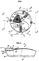
- FIG. 1 is an end view of a ball end mill having a plurality of indexable inserts, according to the present invention;
- FIG. 1A is a side view of the center insert as seen in direction D-D in FIG. 1;
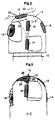
- FIG. 2 is a side elevational view of the ball end mill as seen in direction A-A in FIG. 1;
- FIG. 3 is a side elevational view as seen in direction C-C in FIG. 1;
- FIG. 4 is a side elevational view as seen in direction B-B in FIG. 1;
- FIG. 5 is a side elevational view as seen in direction D-D in FIG. 1;
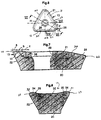
- FIG. 6 is a plan view of the central insert;
- FIG. 7 is a sectional view taken along the line VII-VII in FIG. 6;
- FIG. 8 is a sectional view taken along the line VIII-VIII in FIG. 6;
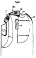
- FIG. 9 is a side elevational view of an alternative enbodiment of a ball end mill according to the invention;
- FIG. 10 is a plan view of the alternative embodiment of the central insert of FIG. 9; and
- FIG. 11 is a side view of the alternative insert as seen from the right hand side in FIG. 10.
- With reference to FIGS. 1 and 2-5, a ball nose end mill has a
cylindrical shank 10 rotatable in a direction of cutting CD around a centrallongitudinal axis 11. The shank terminates in a substantiallyhemispherical cutting face 12 in which there are provided cavities. Thesurface 12 is generated by a radius R' (see FIG. 2). The cavities are shaped to receive indexable cutting inserts 13-19 made preferably of cemented carbide. Acentral insert 13, i.e., the insert located close to thelongitudinal axis 11, includes abottom face 20 and a top face 21 (see FIG. 1A). Theinsert 13 is of substantially triangular shape when viewed in plan, i.e., in a direction toward its top face (see FIG. 1). Thetop face 21 is convexly shaped, more specifically is in the general shape of a portion of a sphere so as to generally conform to the profile of the hemispherical face 12 (see FIG. 3). All of the additional inserts 14-19 of this end mill are substantially rectangular in shape and have planar, parallel bottom and top faces. - The top faces of all of the inserts 13-19 are centrally apertured for the receipt of central clamp screws for securing the inserts to the end mill body. That aperture extends completely through the top and bottom faces of the respective insert. Each insert includes edge faces (e.g., see the
edge faces 22 of the insert 13) which intersect the top face to form cutting edges therewith. - The
central insert 13 has threeidentical cutting edges Bevels cutting edges - The cutting inserts 13-19 are of positive shape, i.e., each of the edge faces thereof intersects the top face at an acute angle. The degree of inclination of the edge faces relative to the top face varies around the insert. More specifically, the inclination of such edge face is greater at the corner regions of the insert than at the intermediate regions of the edge face. By "intermediate" region is meant a region of the edge face situated between the corner regions of the insert. When the inserts 13-19 are mounted in the end mill body, the cutting edges present an effective chip angle that is negative with respect to the radial direction RD (see FIG. 1) and positive with respect to the axial direction 11 (see FIG. 2), which contributes to a smooth and efficient working behavior of the tool.
- First and second ones of the
additional inserts axis 11 and substantially in a common first radial plane P1 which contains the axis 11 (see FIG. 1). A third one of theadditional inserts 15 has a convexly curved active cutting edge arranged substantially in a second plane P2 which is different from the first plane and which contains theaxis 11. Fourth and fifth ones of theinserts axis 11. Thus, theinserts additional inserts 17 has a convexly curved active cutting edge arranged substantially in a third plane P3 which contains theaxis 11 and which is different from both of the first and second planes P1, P2. Alternatively, the sixthadditional insert 17 could be positioned such that its cutting edge is arranged substantially within the second plane P2. - The
inserts central insert 13 and axially forwardly relative to theinserts inserts inserts inserts axis 11. - As shown in FIG. 5, the
inserts main cutting edges inserts cutting edges insert 19, which is visible in FIG. 1, has a design corresponding to that of theinserts Inserts - The cutting edges of the
insert 13 comprise a plurality of main cutting edges 23, 24, 25 each extending between the insert corners, and a plurality of secondary cutting edges 26 extending around the insert corners. Each of the secondary cutting edges 26 is generated by a radius R (see FIG. 1). Each main cutting edge is convexly curved when viewed in a direction toward the respective edge face (see FIG. 1A). When theinsert 13 is viewed in plan (FIG. 1), it can be seen that each of the secondary cutting edges 26 is convexly curved. As a result, the chips produced will be curved and small and thus can be easily transported away from the center of the tool. - Each of the secondary cutting edges 26 intersects two of the main cutting edges. For example, the
secondary cutting edge 26 shown at the lower right in FIG. 1 intersects themain cutting edge 25 atpoint 27′, and intersects themain cutting edge 23 atpoint 27A. As shown in FIG. 6, a line drawn tangent to point 27A coincides with themain cutting edge 23. However, a line drawn tangent to thepoint 27′ forms an obtuse angle β with themain cutting edge 25. Hence, each of the secondary cutting edges is not symmetrical about a plane bisecting the corner. Theedges points 27˝ and 27‴, respectively. - As can be seen in FIG. 1, the
insert 13 is positioned such that themain cutting edge 23 constitutes the "active" main cutting edge (the other main cutting edges 24, 25 being inactive). Also, the secondary cutting edge which constitutes an active secondary cutting edge is the one located adjacent thecenter axis 11 of the mill. It is preferable that the active secondary cutting edge intersect or at least nearly intersect that center axis when viewed in FIG. 1. During a cutting operation, there occurs a relative rotary movement between the chip and the secondary cutting edge which reduces a tendency for edge build-up to occur. Such edge build-up can occur as the result of the adhesion of undesirable material to the cutting edge (the undesirable material coming from the workpiece), and could lead to premature failure of the cutting edge. - The
top face 21 of theinsert 13 is shaped so that each of the threecorner regions 28 is located at a different elevation relative to other portions of thetop face 21. For example, when the insert is viewed along a section line VII-VII which bisects both a corner region and the oppositemain cutting edge 24, acentral portion 36 of the top face which surrounds theaperture 28 is situated at an elevation higher than thecorner region 28, as shown in FIG. 7. Moreover, anintermediate portion 30 of the top face situated between theportion 36 and thecorner region 28 is at a lower elevation than adjacentbeveled portions 31, as is apparent from FIG. 8. Thus, thecentral portion 36 of the top face is elevated in comparison with each corner portion, whereas theintermediate portion 30 is at a lower level than thebevels edges insert 13 is so constructed and arranged that, as shown in FIG. 2, two lines drawn from a center of the radius R′ (FIG. 2) to thepoints 27′, 27˝, respectively, form an acute angle α of about 30 degrees. - The
insert 13 includes a plurality of interjacent surface portions extending from thecentral portion 36 to the mid-region of a respective main cutting edge. As shown in FIG. 7, each interjacent surface portion includes (i) a beveled face 32 (or 31 or 33) having a width a, (ii) a flat part 34 (having a width b) which is parallel to thebottom face 20, and (iii) an obliquely inclined part 35 (having a width c) which connects theflat part 34 with thecentral portion 36. Theflat part 34 lies at a higher elevation than thecentral portion 36. - The width a of each of the beveled faces 31, 32, 33 is such as to provide a substantially constant clearance angle. The width b is larger than the width a of the beveled face. The width a should preferably be approximately one-half the width b.
- Due to such an arrangement of
surface portions - An alternative embodiment of the central insert is shown in FIGS. 9-11 in which the
central insert 13A is provided withrecesses 37 of concave shape, each of which intersects and extends through the respective main cutting edge for the purpose of obtaining increased clearance of the central portion of the tool during a working operation. This contributes to avoiding small pieces breaking off from the edge which could cause tool failure. Thisrecess 37 starts at about thepoint 27′ (or 27˝or 27‴) and extends along a limited portion of the adjacent main cutting edge. At the same time, therecess 37 extends obliquely inwards in relation to the main cutting edge, whereby the extension inwards substantially corresponds to the double the width a of thebeveled face 33. - Further, the
insert 13A is provided with a strengtheningface 38 on its chip surface which extends adjacent to thebeveled face 33. Preferably, the strengtheningface 38 intersects with the beveled face at an angle of 75 to 85 degrees. Theclearance face 22 extends downwards and intersects at an obtuse angle with anedge surface 39 which is obliquely oriented in relation to thebottom face 20. - Although the present invention has been described in connection with preferred embodiments thereof, it will be appreciated by those skilled in the art that additions, modifications, substitutions, end deletions not specifically described may be made without departing from the spirit and scope of the invention as defined in the appended claims.
Claims (15)
- A ball nose end mill for metalworking, comprising a rotary body (10) rotatable about a longitudinal axis thereof, a forward end surface of said body being of generally hemispherical shape and including a plurality of cavities; and a plurality of indexable cutting inserts mounted in respective ones of said cavities; a central one (13) of said inserts being of substantially triangular shape and mounted closely adjacent said longitudinal axis; said central insert (13) including a forwardly facing, substantially triangular top face and a plurality of edge faces intersecting one another to form three corner regions, (27', 27'', 27''') and intersecting said top face to form therewith a plurality of main cutting edges (23, 24, 25), each of said main cutting edges being disposed between two of said corner regions and being convexly curved when viewed in a direction toward the respective edge face; said central insert being mounted such that one of said main cutting edges constitutes an active cutting edge positioned in a cutting orientation; one corner region (27') of said central insert being situated at an end of said active cutting edge (25) and is located immediately adjacent said axis,
characterized in that said plurality of cutting inserts includes additional inserts of generally rectangular shape; each of said additional cutting inserts including a circumferentially facing, generally rectangular top face and a plurality of edge faces intersecting said last-named top face to form therewith a plurality of cutting edges; each of said additional inserts being arranged such that one cutting edge thereof constitutes an active cutting edge positioned in a cutting orientation; said plurality of additional inserts including first and second additional inserts (16 and 19) respectively, whose cutting edges are convexly curved when viewed in a direction toward their respective top faces; said first and second additional inserts having their active cutting edges disposed on opposite sides of said axis and lying generally in a first plane which contains said axis. - A ball nose end mill according to claim 1, wherein said first plane contains said active cutting edge of said front insert.
- A ball nose end mill according to claim 1, wherein said additional inserts include a third additional insert (15) having a convexly curved active cutting edge arranged substantially in a second plane which contains said axis and which is different from said first plane.
- A ball nose end mill according to claim 3, wherein said additional inserts include fourth and fifth additional inserts (14) and (18) respectively having their active cutting edges arranged substantially in a plane which contains said axis and extends substantially perpendicular to said first plane.
- A ball nose end mill according to claim 4, wherein said last-named plane corresponds to said second plane.
- A ball nose end mill according to claim 5, wherein said active cutting edges of said fourth and fifth additional inserts (14, 18) are straight.
- A ball nose end mill according to claim 5, wherein said additional inserts include a sixth additional insert (17) having a convexly curved cutting edge arranged substantially in a third plane which contains said axis and which is different from said first and second planes.
- A ball nose end mill according to claim 7, wherein said third and sixth additional inserts (15 and 17) are located axially rearwardly relative to said central insert (13) and axially forwardly relative to said first and second additional inserts (16 and 19) respectively.
- A ball nose end mill according to claim 8, wherein said first and second additional inserts (16 and 19) are axially forwardly relative to said fourth and fifth additional inserts (14 and 18); said fourth and fifth additional inserts having straight active cutting edges arranged substantially diametrically opposite one another and extending substantially parallel to said axis.
- A ball nose end mill according to claim 8, wherein said top faces of said fourth and fifth additional inserts (14 and 18) are of square shape.
- A ball nose end mill according to claim 1, wherein said first and second additional inserts (16 and 19) are positioned such that their active cutting edges are oriented substantially parallel to said axis.
- An indexable cutting insert (13) adapted for use in a ball nose end mill, comprising a substantially flat bottom face (20) on which said insert is to be supported; a generally convexly shaped top face (21) disposed opposite said bottom face (20); and a plurality of edge faces (22) interconnecting said top and bottom faces, and intersecting said top face at an acuted angle, the intersection of said edge faces with said top face forming a plurality of main cutting edges (23, 24, 25) and a plurality of secondary cutting edges (26), said secondary cutting edges being located at respective corner regions of said insert and being convexly curved when said top face is viewed in plan, each of said main cutting edges being located between respective pairs of said corner regions and being generally convexly curved as viewed in a direction toward its respective edge face, each of said main cutting edges (23, 24, 25) being straight when said top face is viewed in plan; each of said secondary cutting edges (26) intersecting first and second ones of said main cutting edges at first and second points of intersection, respectively, whereby a first line tangent to said first point (27A) of intersection coincides with said first main cutting edge as said top face is viewed in plan, and a second line tangent to said second point of intersection forms an angle (β) with said second main cutting edge as said top face is viewed in plan,
characterized in that said top face (21) includes a plurality of main beveled portions (31, 32, 33) intersecting said edge faces to form said main cutting edges (23, 24, 25), and a plurality of secondary beveled portions intersecting said edge faces to form said secondary cutting edges (26); said generally convex top face including a plurality of intermediate portions (30) each extending downwardly from a central portion (36) of said top face to a respective corner region thereof; each of said intermediate regions (30) being bordered by two of said main beveled portions and extending to a lower elevation than said two main beveled portions. - An indexable cutting insert according to claim 12, wherein said top face includes a plurality of interjacent surface portions extending from a central flat portion of said top surface toward the mid-region of respective ones of said main cutting edges; said interjacent surface portions (31, 32, 33, 34, 35) including a flat part (34) disposed at an elevation which is higher than said central portion (36); said central portion being disposed at an elevation higher than said corner regions.
- An indexable cutting insert according to claim 12, wherein said top face (21) includes a plurality of main beveled portions (31, 32, 33) intersecting said edge faces (22) to form said main cutting edges (23, 24, 25), and a plurality of flat surface portions (34) disposed inwardly of the mid-regions of respective ones of said main beveled portions; said flat surface portions (34) being oriented parallel to said bottom face (20).
- An indexable cutting insert according to claim 12, wherein said top face (21) includes a central portion (36); a central aperture (29) extending through said insert from said top face to said bottom face; said top face (21) including a flat surface (34) situated between said central portion and a mid-region of each of said main cutting edges; an inclined face (35) interconnecting said central portion (36) with each of said flat surfaces (34).
Applications Claiming Priority (2)
| Application Number | Priority Date | Filing Date | Title |
|---|---|---|---|
| SE9002171 | 1990-06-19 | ||
| SE9002171A SE466435B (en) | 1990-06-19 | 1990-06-19 | RADIEPINNFRIES WITH FRIENDS |
Publications (3)
| Publication Number | Publication Date |
|---|---|
| EP0462954A2 EP0462954A2 (en) | 1991-12-27 |
| EP0462954A3 EP0462954A3 (en) | 1992-06-03 |
| EP0462954B1 true EP0462954B1 (en) | 1994-08-31 |
Family
ID=20379807
Family Applications (1)
| Application Number | Title | Priority Date | Filing Date |
|---|---|---|---|
| EP91850160A Expired - Lifetime EP0462954B1 (en) | 1990-06-19 | 1991-06-12 | Ball end mill and throw away insert for such end mill |
Country Status (8)
| Country | Link |
|---|---|
| US (1) | US5190419A (en) |
| EP (1) | EP0462954B1 (en) |
| JP (1) | JPH04226827A (en) |
| AT (1) | ATE110607T1 (en) |
| BR (1) | BR9102491A (en) |
| DE (1) | DE69103691T2 (en) |
| ES (1) | ES2059102T3 (en) |
| SE (1) | SE466435B (en) |
Families Citing this family (19)
| Publication number | Priority date | Publication date | Assignee | Title |
|---|---|---|---|---|
| JP2513645Y2 (en) * | 1991-05-22 | 1996-10-09 | 三菱マテリアル株式会社 | Ball end mill |
| JPH06297208A (en) * | 1993-03-12 | 1994-10-25 | Valenite Inc | Improved type cutting tool and cutting insert therefor |
| US5542792A (en) * | 1993-12-21 | 1996-08-06 | Waukesha Cutting Tools, Inc. | Cutting device with removable nosepiece |
| DE19624342C1 (en) * | 1996-06-19 | 1997-12-11 | Walter Ag | Cutting insert and milling cutter, in particular ball end mill or copy milling cutter |
| IL120137A0 (en) * | 1997-02-03 | 1997-06-10 | Iscar Ltd | Cutting insert |
| US5921720A (en) * | 1998-01-23 | 1999-07-13 | Lemke; Carl | Ball nose cutting tool with center mounted tool bits |
| US6802676B2 (en) | 2001-03-02 | 2004-10-12 | Valenite Llc | Milling insert |
| US6722826B2 (en) | 2001-09-11 | 2004-04-20 | Brian M. Cavanaugh | Internal cavity cutting tool with stable support |
| SE529065C2 (en) * | 2004-10-20 | 2007-04-24 | Seco Tools Ab | Cutting tool where the insert has a chip channel that cuts the release surface |
| KR100887787B1 (en) * | 2007-08-29 | 2009-03-09 | 대구텍 주식회사 | Cutting insert |
| IL211444A0 (en) * | 2011-02-27 | 2011-06-30 | Kennametal Inc | High feed cutting insert |
| US20130220485A1 (en) * | 2012-02-29 | 2013-08-29 | Svante Larsson | Cutting tool |
| CN102962505B (en) * | 2012-11-12 | 2015-09-23 | 大连经济技术开发区伊达工具有限公司 | A kind of side set PCD rose cutter |
| RU2018130486A (en) | 2013-07-31 | 2019-03-20 | Дайдо Диэ энд Моулд Стил Солюшенз Ко., Лтд. | METHOD FOR MAKING KNEE, CUTTING TOOL AND KNEE |
| CN106061661B (en) * | 2014-02-26 | 2018-01-19 | 株式会社泰珂洛 | Bit replacing formula rotary cutting tool |
| US9700947B2 (en) | 2014-06-27 | 2017-07-11 | Kennametal Inc. | Ballnose cutting tool and ballnose cutting insert |
| AT15151U1 (en) * | 2016-02-29 | 2017-01-15 | Ceratizit Austria Gmbh | cutting insert |
| US10632548B2 (en) * | 2017-11-20 | 2020-04-28 | Iscar, Ltd. | Triangular-shaped indexable cutting insert having recessed side surfaces and rotary cutting tool |
| WO2021255919A1 (en) * | 2020-06-19 | 2021-12-23 | 住友電工ハードメタル株式会社 | End mill |
Family Cites Families (10)
| Publication number | Priority date | Publication date | Assignee | Title |
|---|---|---|---|---|
| US4252480A (en) * | 1979-05-03 | 1981-02-24 | Sumitomo Electric Industries, Ltd. | Throw away insert and end mills |
| DE8125049U1 (en) * | 1981-08-27 | 1983-02-10 | Komet Stahlhalter- Und Werkzeugfabrik Robert Breuning Gmbh, 7122 Besigheim | TRIANGULAR INSERT PLATE FOR TURNING TOOLS |
| JPS5973216A (en) * | 1982-10-19 | 1984-04-25 | Toshiba Tungaloy Co Ltd | Ball end mill |
| GB2135612B (en) * | 1983-02-22 | 1986-03-12 | Ingersoll Mach & Tool Co | Ballnose end mill and cutting insert therefor |
| US4618296A (en) * | 1983-09-14 | 1986-10-21 | Gte Valeron Corporation | Cutting tool and insert therefor |
| US4566827A (en) * | 1984-11-30 | 1986-01-28 | Ingersoll Cutting Tool Company | Ballnose end mill and insert therefor |
| DE3618574C2 (en) * | 1985-06-06 | 1989-11-02 | Mitsubishi Kinzoku K.K., Tokio/Tokyo, Jp | POSITIVE INSERT |
| JPS6446116U (en) * | 1987-09-17 | 1989-03-22 | ||
| US4838739A (en) * | 1987-09-18 | 1989-06-13 | Gte Valenite Corporation | Ball nose end mill and method of manufacture |
| JPH0247115U (en) * | 1988-09-27 | 1990-03-30 |
-
1990
- 1990-06-19 SE SE9002171A patent/SE466435B/en not_active IP Right Cessation
-
1991
- 1991-06-12 EP EP91850160A patent/EP0462954B1/en not_active Expired - Lifetime
- 1991-06-12 DE DE69103691T patent/DE69103691T2/en not_active Expired - Fee Related
- 1991-06-12 ES ES91850160T patent/ES2059102T3/en not_active Expired - Lifetime
- 1991-06-12 AT AT91850160T patent/ATE110607T1/en not_active IP Right Cessation
- 1991-06-13 JP JP3142011A patent/JPH04226827A/en active Pending
- 1991-06-17 BR BR919102491A patent/BR9102491A/en not_active IP Right Cessation
- 1991-06-19 US US07/717,644 patent/US5190419A/en not_active Expired - Fee Related
Also Published As
| Publication number | Publication date |
|---|---|
| US5190419A (en) | 1993-03-02 |
| SE9002171L (en) | 1991-12-20 |
| BR9102491A (en) | 1992-01-21 |
| DE69103691D1 (en) | 1994-10-06 |
| JPH04226827A (en) | 1992-08-17 |
| ATE110607T1 (en) | 1994-09-15 |
| EP0462954A2 (en) | 1991-12-27 |
| SE9002171D0 (en) | 1990-06-19 |
| SE466435B (en) | 1992-02-17 |
| ES2059102T3 (en) | 1994-11-01 |
| DE69103691T2 (en) | 1994-12-22 |
| EP0462954A3 (en) | 1992-06-03 |
Similar Documents
| Publication | Publication Date | Title |
|---|---|---|
| US5190419A (en) | Ball end mill and throw away insert for such end mill | |
| EP0936015B1 (en) | Cutting tool and cutting insert | |
| US5032049A (en) | Indexable cutting insert | |
| US6543970B1 (en) | Double negative cutting insert for tools for chip removing machining | |
| US4632607A (en) | Indexable cutting insert | |
| US6074137A (en) | Cutting tool assembly | |
| KR840002187B1 (en) | Cutting insert | |
| KR100988410B1 (en) | Tangential cutting inserts and milling cutters | |
| US4930945A (en) | Insert rotary cutter | |
| KR100561562B1 (en) | Drill and cutting insert therefor | |
| EP1539413B1 (en) | Cutting insert and method | |
| US5741095A (en) | Cutting tool and insert therefor | |
| US7121772B2 (en) | Cutting insert | |
| US5827016A (en) | Octagonal milling insert with anti-rattle configuration and strengthened cutting edges | |
| US8506208B2 (en) | Shim plate for milling tools for chip removing machining as well as a milling tool having such a shim plate | |
| EP0232692B1 (en) | Indexable cutting insert | |
| KR19990028266A (en) | Cutting inserts, cutting tools and methods | |
| EP0289651B1 (en) | Insert boring tool | |
| EP0941796A2 (en) | A milling cutting insert and a milling cutter | |
| EP0112806B1 (en) | Cutting insert | |
| US4834591A (en) | Indexable cutter insert | |
| EP1355755B1 (en) | Cutting tool and cutting inserts | |
| CA2045365A1 (en) | Ball end mill and throw away insert for such end mill | |
| EP0295487A1 (en) | Neutral positive geometry insert | |
| JPH10235511A (en) | Indexable tip |
Legal Events
| Date | Code | Title | Description |
|---|---|---|---|
| PUAI | Public reference made under article 153(3) epc to a published international application that has entered the european phase |
Free format text: ORIGINAL CODE: 0009012 |
|
| AK | Designated contracting states |
Kind code of ref document: A2 Designated state(s): AT BE CH DE DK ES FR GB IT LI LU NL SE |
|
| PUAL | Search report despatched |
Free format text: ORIGINAL CODE: 0009013 |
|
| AK | Designated contracting states |
Kind code of ref document: A3 Designated state(s): AT BE CH DE DK ES FR GB IT LI LU NL SE |
|
| 17P | Request for examination filed |
Effective date: 19920623 |
|
| 17Q | First examination report despatched |
Effective date: 19930729 |
|
| GRAA | (expected) grant |
Free format text: ORIGINAL CODE: 0009210 |
|
| ITF | It: translation for a ep patent filed | ||
| AK | Designated contracting states |
Kind code of ref document: B1 Designated state(s): AT BE CH DE DK ES FR GB IT LI LU NL SE |
|
| PG25 | Lapsed in a contracting state [announced via postgrant information from national office to epo] |
Ref country code: NL Effective date: 19940831 Ref country code: LI Effective date: 19940831 Ref country code: DK Effective date: 19940831 Ref country code: CH Effective date: 19940831 Ref country code: BE Effective date: 19940831 |
|
| REF | Corresponds to: |
Ref document number: 110607 Country of ref document: AT Date of ref document: 19940915 Kind code of ref document: T |
|
| REF | Corresponds to: |
Ref document number: 69103691 Country of ref document: DE Date of ref document: 19941006 |
|
| REG | Reference to a national code |
Ref country code: ES Ref legal event code: FG2A Ref document number: 2059102 Country of ref document: ES Kind code of ref document: T3 |
|
| PG25 | Lapsed in a contracting state [announced via postgrant information from national office to epo] |
Ref country code: SE Effective date: 19941130 |
|
| REG | Reference to a national code |
Ref country code: CH Ref legal event code: PL |
|
| ET | Fr: translation filed | ||
| NLV1 | Nl: lapsed or annulled due to failure to fulfill the requirements of art. 29p and 29m of the patents act | ||
| PGFP | Annual fee paid to national office [announced via postgrant information from national office to epo] |
Ref country code: NL Payment date: 19950628 Year of fee payment: 5 |
|
| PLBE | No opposition filed within time limit |
Free format text: ORIGINAL CODE: 0009261 |
|
| STAA | Information on the status of an ep patent application or granted ep patent |
Free format text: STATUS: NO OPPOSITION FILED WITHIN TIME LIMIT |
|
| 26N | No opposition filed | ||
| PGFP | Annual fee paid to national office [announced via postgrant information from national office to epo] |
Ref country code: AT Payment date: 19980615 Year of fee payment: 8 |
|
| PGFP | Annual fee paid to national office [announced via postgrant information from national office to epo] |
Ref country code: LU Payment date: 19980629 Year of fee payment: 8 |
|
| PG25 | Lapsed in a contracting state [announced via postgrant information from national office to epo] |
Ref country code: LU Free format text: LAPSE BECAUSE OF NON-PAYMENT OF DUE FEES Effective date: 19990612 Ref country code: AT Free format text: LAPSE BECAUSE OF NON-PAYMENT OF DUE FEES Effective date: 19990612 |
|
| PGFP | Annual fee paid to national office [announced via postgrant information from national office to epo] |
Ref country code: GB Payment date: 20000607 Year of fee payment: 10 |
|
| PGFP | Annual fee paid to national office [announced via postgrant information from national office to epo] |
Ref country code: FR Payment date: 20000612 Year of fee payment: 10 |
|
| PGFP | Annual fee paid to national office [announced via postgrant information from national office to epo] |
Ref country code: DE Payment date: 20000614 Year of fee payment: 10 |
|
| PGFP | Annual fee paid to national office [announced via postgrant information from national office to epo] |
Ref country code: ES Payment date: 20000623 Year of fee payment: 10 |
|
| PG25 | Lapsed in a contracting state [announced via postgrant information from national office to epo] |
Ref country code: GB Free format text: LAPSE BECAUSE OF NON-PAYMENT OF DUE FEES Effective date: 20010612 |
|
| PG25 | Lapsed in a contracting state [announced via postgrant information from national office to epo] |
Ref country code: ES Free format text: LAPSE BECAUSE OF NON-PAYMENT OF DUE FEES Effective date: 20010613 |
|
| GBPC | Gb: european patent ceased through non-payment of renewal fee |
Effective date: 20010612 |
|
| PG25 | Lapsed in a contracting state [announced via postgrant information from national office to epo] |
Ref country code: FR Free format text: LAPSE BECAUSE OF NON-PAYMENT OF DUE FEES Effective date: 20020228 |
|
| PG25 | Lapsed in a contracting state [announced via postgrant information from national office to epo] |
Ref country code: DE Free format text: LAPSE BECAUSE OF NON-PAYMENT OF DUE FEES Effective date: 20020403 |
|
| REG | Reference to a national code |
Ref country code: ES Ref legal event code: FD2A Effective date: 20030203 |
|
| PG25 | Lapsed in a contracting state [announced via postgrant information from national office to epo] |
Ref country code: IT Free format text: LAPSE BECAUSE OF NON-PAYMENT OF DUE FEES Effective date: 20050612 |