EP0461649A2 - Méthode et appareil d'enregistrement et de reproduction - Google Patents
Méthode et appareil d'enregistrement et de reproduction Download PDFInfo
- Publication number
- EP0461649A2 EP0461649A2 EP19910109707 EP91109707A EP0461649A2 EP 0461649 A2 EP0461649 A2 EP 0461649A2 EP 19910109707 EP19910109707 EP 19910109707 EP 91109707 A EP91109707 A EP 91109707A EP 0461649 A2 EP0461649 A2 EP 0461649A2
- Authority
- EP
- European Patent Office
- Prior art keywords
- area
- reference period
- allocated
- compression reference
- signal
- Prior art date
- Legal status (The legal status is an assumption and is not a legal conclusion. Google has not performed a legal analysis and makes no representation as to the accuracy of the status listed.)
- Granted
Links
Images


Classifications
-
- G—PHYSICS
- G11—INFORMATION STORAGE
- G11B—INFORMATION STORAGE BASED ON RELATIVE MOVEMENT BETWEEN RECORD CARRIER AND TRANSDUCER
- G11B20/00—Signal processing not specific to the method of recording or reproducing; Circuits therefor
- G11B20/00007—Time or data compression or expansion
-
- G—PHYSICS
- G11—INFORMATION STORAGE
- G11B—INFORMATION STORAGE BASED ON RELATIVE MOVEMENT BETWEEN RECORD CARRIER AND TRANSDUCER
- G11B27/00—Editing; Indexing; Addressing; Timing or synchronising; Monitoring; Measuring tape travel
- G11B27/02—Editing, e.g. varying the order of information signals recorded on, or reproduced from, record carriers
- G11B27/031—Electronic editing of digitised analogue information signals, e.g. audio or video signals
-
- G—PHYSICS
- G11—INFORMATION STORAGE
- G11B—INFORMATION STORAGE BASED ON RELATIVE MOVEMENT BETWEEN RECORD CARRIER AND TRANSDUCER
- G11B27/00—Editing; Indexing; Addressing; Timing or synchronising; Monitoring; Measuring tape travel
- G11B27/10—Indexing; Addressing; Timing or synchronising; Measuring tape travel
- G11B27/19—Indexing; Addressing; Timing or synchronising; Measuring tape travel by using information detectable on the record carrier
- G11B27/28—Indexing; Addressing; Timing or synchronising; Measuring tape travel by using information detectable on the record carrier by using information signals recorded by the same method as the main recording
- G11B27/30—Indexing; Addressing; Timing or synchronising; Measuring tape travel by using information detectable on the record carrier by using information signals recorded by the same method as the main recording on the same track as the main recording
- G11B27/3027—Indexing; Addressing; Timing or synchronising; Measuring tape travel by using information detectable on the record carrier by using information signals recorded by the same method as the main recording on the same track as the main recording used signal is digitally coded
- G11B27/3036—Time code signal
-
- H—ELECTRICITY
- H04—ELECTRIC COMMUNICATION TECHNIQUE
- H04N—PICTORIAL COMMUNICATION, e.g. TELEVISION
- H04N9/00—Details of colour television systems
- H04N9/79—Processing of colour television signals in connection with recording
- H04N9/80—Transformation of the television signal for recording, e.g. modulation, frequency changing; Inverse transformation for playback
- H04N9/804—Transformation of the television signal for recording, e.g. modulation, frequency changing; Inverse transformation for playback involving pulse code modulation of the colour picture signal components
- H04N9/8042—Transformation of the television signal for recording, e.g. modulation, frequency changing; Inverse transformation for playback involving pulse code modulation of the colour picture signal components involving data reduction
- H04N9/8045—Transformation of the television signal for recording, e.g. modulation, frequency changing; Inverse transformation for playback involving pulse code modulation of the colour picture signal components involving data reduction using predictive coding
-
- H—ELECTRICITY
- H04—ELECTRIC COMMUNICATION TECHNIQUE
- H04N—PICTORIAL COMMUNICATION, e.g. TELEVISION
- H04N9/00—Details of colour television systems
- H04N9/79—Processing of colour television signals in connection with recording
- H04N9/80—Transformation of the television signal for recording, e.g. modulation, frequency changing; Inverse transformation for playback
- H04N9/808—Transformation of the television signal for recording, e.g. modulation, frequency changing; Inverse transformation for playback involving pulse code modulation of the composite colour video-signal
- H04N9/8085—Transformation of the television signal for recording, e.g. modulation, frequency changing; Inverse transformation for playback involving pulse code modulation of the composite colour video-signal with processing of the sound signal
- H04N9/8087—Transformation of the television signal for recording, e.g. modulation, frequency changing; Inverse transformation for playback involving pulse code modulation of the composite colour video-signal with processing of the sound signal using time division multiplex of the PCM audio and PCM video signals
- H04N9/8088—Transformation of the television signal for recording, e.g. modulation, frequency changing; Inverse transformation for playback involving pulse code modulation of the composite colour video-signal with processing of the sound signal using time division multiplex of the PCM audio and PCM video signals with insertion of the PCM audio signals in the vertical blanking interval of the PCM video signal
-
- H—ELECTRICITY
- H04—ELECTRIC COMMUNICATION TECHNIQUE
- H04N—PICTORIAL COMMUNICATION, e.g. TELEVISION
- H04N9/00—Details of colour television systems
- H04N9/79—Processing of colour television signals in connection with recording
- H04N9/87—Regeneration of colour television signals
-
- G—PHYSICS
- G11—INFORMATION STORAGE
- G11B—INFORMATION STORAGE BASED ON RELATIVE MOVEMENT BETWEEN RECORD CARRIER AND TRANSDUCER
- G11B2220/00—Record carriers by type
- G11B2220/90—Tape-like record carriers
-
- G—PHYSICS
- G11—INFORMATION STORAGE
- G11B—INFORMATION STORAGE BASED ON RELATIVE MOVEMENT BETWEEN RECORD CARRIER AND TRANSDUCER
- G11B2220/00—Record carriers by type
- G11B2220/90—Tape-like record carriers
- G11B2220/91—Helical scan format, wherein tracks are slightly tilted with respect to tape direction, e.g. VHS, DAT, DVC, AIT or exabyte
- G11B2220/913—Digital audio tape [DAT] format
-
- H—ELECTRICITY
- H04—ELECTRIC COMMUNICATION TECHNIQUE
- H04N—PICTORIAL COMMUNICATION, e.g. TELEVISION
- H04N5/00—Details of television systems
- H04N5/76—Television signal recording
- H04N5/78—Television signal recording using magnetic recording
- H04N5/782—Television signal recording using magnetic recording on tape
- H04N5/783—Adaptations for reproducing at a rate different from the recording rate
Definitions
- the present invention relates to technology of concurrently recording and reproducing digital video signals for a dynamic picture and digital audio signals.
- a conventional digital audio tape recorder (hereafter referred to as "DAT") is designed to record and reproduce only digital audio signals. It will be very useful if the DAT can simultaneously record or reproduce a digital audio signal and another signal, such as a digital video signal for a dynamic picture.
- an N-bit digital signal (N: integer) is formed by an image area, an audio area and a control area.
- Compressed digital video signals for multiple screens that constitute a dynamic picture are allocated in the image area in each compression reference period.
- a digital audio signal in each compression reference period is allocated in the audio area in that compression reference period.
- the digital signal is recorded and reproduced in N bits.
- an N-bit digital signal is formed by an image area, an audio area and a control area.
- Compressed digital video signals for multiple screens that constitute a dynamic picture are allocated in the image area in each compression reference period.
- a digital audio signal in each compression reference period is allocated in the audio area in that compression reference period.
- Data concerning the digital signal to be allocated in the image area or audio area is allocated in the control area.
- the digital signal is recorded and reproduced in N bits.
- an N-bit digital signal is formed by an image area, an audio area and a control area.
- Compressed digital video signals for multiple screens that constitute a dynamic picture are allocated in the image area in each compression reference period.
- a digital audio signal in each compression reference period is allocated in the audio area in that compression reference period.
- In the control area in each compression reference period is allocated data concerning the digital signal to be allocated in the image areas or audio areas in the following compression reference periods.
- the digital signal is recorded and reproduced in N bits.
- an N-bit digital signal is formed by an image area, an audio area and a control area.
- Compressed digital video signals for multiple screens that constitute a dynamic picture are allocated in the image area in each compression reference period.
- a digital audio signal in each compression reference period is allocated in the audio area in that compression reference period.
- image data for one screen is allocated first, then difference image data for multiple screens are allocated.
- the digital signal is recorded and reproduced in N bits.
- an N-bit digital signal is formed by an image area, an audio area and a control area.
- Compressed digital video signals for multiple screens that constitute a dynamic picture are allocated in the image area in each compression reference period.
- a digital audio signal in each compression reference period is allocated in the audio area in that compression reference period.
- the digital signal is recorded and reproduced in N bits. Recording and reproducing of the digital video signal and digital audio signal are executed at the same timing with the compression reference period as a unit.
- an N-bit digital signal is formed by an image area, an audio area and a control area.
- Compressed digital video signals for multiple screens that constitute a dynamic picture are allocated in the image area in each compression reference period.
- a digital audio signal in each compression reference period is allocated in the audio area in that compression reference period.
- Expansion means expands compressed digital video signal separated from the image area of the reproduced signal.
- Output means repeatedly outputs expanded image data for one screen.
- an N-bit digital signal is formed by an image area, an audio area and a control area.
- Compressed digital video signals for multiple screens that constitute a dynamic picture are allocated in the image area in each compression reference period.
- a digital audio signal in each compression reference period is allocated in the audio area in that compression reference period.
- image data for one screen is allocated first, then difference image data for multiple screens are allocated.
- a digital signal recorded in N bits is reproduced.
- Expansion means expands reference image data in the image area in each compression reference period of the reproduced signal.
- Output means repeatedly outputs expanded image data for one screen.
- an N-bit digital signal is formed by an image area, an audio area and a control area.
- Compressed digital video signals for multiple screens that constitute a dynamic picture are allocated in the image area in each compression reference period.
- a digital audio signal in each compression reference period is allocated in the audio area in that compression reference period.
- image data for one screen is allocated first, then difference image data for multiple screens are allocated.
- Data indicating presence of a scene change is allocated in a compression reference period of the control area immediately before the scene change.
- a digital signal recorded in N bits is reproduced.
- Expansion means expands reference image data in the image area in a compression reference period after the scene change based on the data indicating presence of the scene change allocated in the control area.
- Output means repeatedly outputs expanded image data for one screen.
- an N-bit digital signal is formed by an image area, an audio area and a control area.
- Compressed digital video signals for multiple screens that constitute a dynamic picture are allocated in the image area in each compression reference period.
- a digital audio signal in each compression reference period is allocated in the audio area in that compression reference period.
- a digital signal recorded in N bits is reproduced.
- Expansion means expands compressed digital video signals for multiple screens separated from the image area in each compression reference period of the reproduced signal.
- Output means repeatedly outputs expanded image data for one screen every predetermined number of screens until next compressed image data for one screen is acquired.
- an N-bit digital signal is formed by an image area, an audio area and a control area.
- Compressed digital video signals for multiple screens that constitute a dynamic picture are allocated in the image area in each compression reference period.
- a digital audio signal in each compression reference period is allocated in the audio area in that compression reference period.
- In the control area in each compression reference period are allocated first data and second data concerning digital video signals to be allocated in the image areas in immediately before and immediately after compression reference periods.
- a digital signal recorded in N bits is reproduced.
- Data detecting means detects the first and second data from the control areas of the respective compression reference periods of the reproduced signal.
- compressed digital video signals for multiple screens separated from the image areas in the individual compression reference periods of the reproduced signal are reproduced on the basis of the first and second data, respectively.
- an N-bit digital signal is formed by an image area, an audio area and a control area.
- Compressed digital video signals for multiple screens that constitute a dynamic picture are allocated in the image area in each compression reference period.
- a digital audio signal in each compression reference period is allocated in the audio area in that compression reference period.
- a time code is allocated in the control area in each compression reference period.
- a digital signal recorded in N bits is reproduced.
- an N-bit digital signal is formed by an image area, an audio area and a control area.
- Compressed digital video signals for multiple screens that constitute a dynamic picture are allocated in the image area in each compression reference period.
- a digital audio signal in each compression reference period is allocated in the audio area in that compression reference period.
- a digital signal recorded in N bits is reproduced.
- Reproduction at a normal speed and reproduction at a predetermined fast speed are alternately executed.
- Expansion means expands a compressed digital video signal separated from the image area of a signal reproduced at the normal speed.
- Output means repeatedly outputs expanded image data for one screen.
- an N-bit digital signal is formed by an image area, an audio area and a control area.
- Compressed digital video signals for multiple screens that constitute a dynamic picture are allocated in the image area in each compression reference period.
- a digital audio signal in each compression reference period is allocated in the audio area in that compression reference period.
- image data for one screen is allocated first, then difference image data for multiple screens are allocated.
- a digital signal recorded in N bits is reproduced.
- Reproduction at a normal speed and reproduction at a predetermined fast speed are alternately executed.
- Expansion means expands a compressed digital video signal separated from the image area of a signal reproduced at the normal speed.
- Output means repeatedly outputs expanded image data for one screen.
- an N-bit digital signal is formed by an image area, an audio area and a control area.
- Compressed digital video signals for multiple screens that constitute a dynamic picture are allocated in the image area in each compression reference period.
- a digital audio signal in each compression reference period is allocated in the audio area in that compression reference period.
- the digital video signal is allocated in the image area in each compression reference period in such a way that reference image data for one screen is allocated first, then difference image data for multiple screens are allocated. That area where difference compressed image data for multiple screens are to be allocated is changed in accordance with the amount of data, and data indicating the change is allocated in the control area.
- a digital signal recorded in N bits is reproduced.
- an N-bit digital signal is formed by an image area, an audio area and a control area.
- Compressed digital video signals for multiple screens that constitute a dynamic picture are allocated in the image area in each compression reference period.
- a digital audio signal in each compression reference period is allocated in the audio area in that compression reference period.
- a digital signal recorded in N bits is reproduced.
- a normal reproduction mode in a predetermined number of compression reference periods and a reproduction pause mode in M periods (M: an integer equal to or greater than 1) of the predetermined number of compression reference periods are alternately executed.
- Expansion means expands a compressed digital video signal separated from the image area of a signal reproduced in the normal reproduction mode in the predetermined number of compression reference periods.
- Output means outputs expanded image data for each screen repeatedly by (M + 1) times.
- a digital signal recorded in N bits, an image area, an audio area and a control area being formed by part of N bits, compressed digital video signals for multiple screens constituting a dynamic picture and allocated in the image area in each compression reference period, a digital audio signal in each compression reference period allocated in the audio area in that compression reference period, and sync codes allocated at predetermined intervals in the control area in each compression reference period, are reproduced from a first recording medium and are recorded on another recording medium.
- Detecting means detects the sync codes from the control area of the signal reproduced from the first recording medium.
- Control means controls a period for recording the signal on the another recording medium based on the sync codes.
- a digital signal recorded in N bits, an image area, an audio area and a control area being formed by part of N bits, compressed digital video signals for multiple screens constituting a dynamic picture and allocated in the image area in each compression reference period, a digital audio signal in each compression reference period allocated in the audio area in that compression reference period, and a time code allocated at predetermined intervals in the control area in each compression reference period, are reproduced from a first recording medium and are recorded on another recording medium.
- Detecting means detects the time code from the control area of the signal reproduced from the first recording medium.
- Control means controls a period for recording the signal on the another recording medium based on the time code.
- an N-bit digital signal is formed by an image area, an audio area and a control area.
- a dynamic picture area and a still picture area are selectively formed in the image area.
- Compressed digital video signals for multiple screens constituting a dynamic picture are sequentially allocated as one unit in the dynamic picture area.
- a digital video signal for one screen constituting a still picture is sequentially allocated as one unit in the still picture image area.
- a digital video signal carrying a great deal of information is compressed to reduce the amount of information for recording and reproduction, and at the same time, the information as to how the signal has been compressed is recorded and reproduced. This makes it possible to concurrently record or reproduce the digital video signal for a dynamic picture and a digital audio signal without problems.
- a DAT is exemplified as a recording and reproducing apparatus.
- Fig. 2 shows the format of a digital signal to be recorded and reproduced in the embodiment.
- bits b15-b4 are regarded as an image area, bits b3-b1 as an audio area, and bit b0 as a control area.
- Record data is formed with a predetermined period (one second in this embodiment) as a unit period (hereafter referred to as "compression reference period") according to the embodiment.
- compression reference period a unit period
- the image area has 1152000 bits, the audio area 2888000 bits, and the control area 96000 bits.
- Video signals in the NTSC system are used in this embodiment, and 30 frames of image data will be put in the image area during the compression reference period.
- the 30 frames of image data contain too much information.
- one frame contains pixel data of 256 H x 240 V, and a brightness signal Y, a red difference signal U, and a blue difference signal V each consist of 8 bits
- the 30-frame image data therefore will be compressed within a range of 1152000 bits.
- pixel data of 256 H x 240 V will be reduced to a half by a sub-sampling process.
- the total bits of the brightness signal Y, the red difference signal U, and the blue difference signal V, 24 bits, are compressed into 9 bits.
- Image data of the second frame to the 29th frame are each considered as difference compressed image data with image data of the first frame taken as reference data.
- the amount of information in the difference compressed image data is 27200 bits, for example.
- the remaining 86720 bits are used to adjust a fixed length.
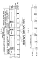
- Fig. 4 illustrates an example of the format of record data.
- the reference image data, VB1, VB2, ... that correspond to the image data of the first frame are placed, followed by the difference compressed image data, ⁇ c1, ⁇ c2, ... ⁇ c29, that correspond to the image data of the respective second to 29th frames.
- Audio data for each compression reference period is put in the audio area in that reference period.
- Audio data consists of within 288000 bits.
- the ADPCM system for example, is used as a coding system for audio data to compress the data.
- a sampling frequency is 32 kHz
- the remaining 32000 bits are empty and are used to adjust the bit rate.
- the audio area is formed of three bits b3-b1 out of 16 bits b15-b0 of a digital signal.
- audio data is placed in 8 bits of every 9 bits and the remaining 1 bit is empty and is used to adjust the bit rate.
- 32 kHz x 8 bits 256 kbps.
- the control area in each compression reference period includes sync code portions, mode code portions, and control code portions.
- each compression reference period There are multiple sync code portions provided in each compression reference period; four sync code portions are arranged at 0.25-sec intervals in this embodiment. In each sync code portion is secured an area of, for example, 64 x 1 bits. A framing code is used as a sync code, and the four sync code portions respectively have different types of sync codes 1-4.
- the sync code portion which corresponds to immediately before the next compression reference period, is given the sync code 1.
- the other previously-located, three sync code portions are given the sync codes 4-2, respectively.
- Each mode code portion follows the associated sync code portion; four mode code portions are provided at 0.25-sec intervals. In each mode code portion, an area of 64 x 1 bits is secured.
- the same data is put in the four mode code portions in each compression reference period.
- the mode code portion contains data concerned with image data, audio data and the like to be provided in the next compression reference period.
- the mode code portion contains data indicating the presence of a scene change besides the aforementioned data concerning image data and audio data, when there is a scene change in the next compression reference period, as will be described later,
- Each control code portion follows the associated mode code portion, i.e., four control code portions are provided in each compression reference period. An area of 23136 x 1 bits is secured in each control code portion.
- the same data is allocated in the four control code portions in each compression reference period.
- the control code portion contains a micro code for expansion of image data to be allocated in the next compression reference period, making it possible to cope with any compression system at the time of reproduction.
- guard area of 736 bits, each bit set to "0", provided between the control code portion and the sync code portion.
- the mode code and control code can efficiently be acquired wherever reproduction starts. It is therefore possible to smoothly control the operation of a processing system for reproduced signals as will be described later.
- Fig. 6 illustrates the structure of record data in the case where a scene change occurs.
- the recording state of image data is reset in a midway in the compression reference period (refer to a point tc in Fig. 6).
- the reference image data VB N+2 after the scene change and the difference compressed image data ⁇ c1, ⁇ c2, ... are recorded one after another in the image area.
- the data recording state in the control area is also reset accordingly, and the sync code portion having the sync code 1 is placed immediately before the reference image data VB N+2 .
- Data indicating the presence of the scene change is allocated in the mode code portion in the compression reference period coming before the scene change.
- Figs. 1A and 1B exemplify a signal processor that is used when the DAT records and reproduces the record data as shown in Figs. 4 and 6.
- the recording system of the processor will be explained first.
- a color video signal SV of the NTSC system sent to a video-in terminal 11 is amplified by an amplifier 12.
- the amplified signal is then supplied to a decoder 13.
- the decoder 13 sends a brightness signal Y, red difference signal U, and blue difference signal V to an A/D converter 14.
- the video signal SV from the amplifier 12 is also supplied to a sync separator/clock generator 15.
- This circuit 15 then outputs a clock CK R1 having a frequency of 8 fsc/3 (fsc: color subcarrier frequency of 3.58 MHz) in synchronism with a sync signal for the video signal SV.
- This clock CK R1 is supplied as a sampling clock to the A/D converter 14.
- the A/D converter 14 samples the signals Y, U, and V so that the number of samples per effective horizontal period is 256 samples, and converts the signals to digital signals with one sample consisting of 8 bits.
- the signals Y, U and V from the A/D converter 14 are sent to a movable terminal of a selection switch 16.
- a control line is not shown, the selection switch 16 is driven under the control of a controller 110 including a CPU; the switch 16 is switched in order to the side a, b, c, a, ... at the end of each frame period.
- the selection switch 16 has fixed terminals on the sides a-c connected to the input terminals of the respective RAMs 17a-17c.
- a RAM controller 120 controls write and read access to the RAMs 17a-17c. The operation of the RAM controller 120 is under the control of the controller 110.
- the RAM controller 120 receives the clock CK R1 from the clock generator 15 as well as a vertical sync signal VD R and a horizontal sync signal HD R , both as reference sync signals.
- the controller 110 receives a clock CK R2 having a frequency of 8 fsc as a master clock from the generator 15, and the vertical sync signal VD R and the horizontal sync signal HD R as reference sync signals.
- the controller 110 receives a bit clock BCK (see B in Fig. 7) and a clock LRCK (see A in Fig. 7) for selection of right and left channels from a DAT 130. Both clocks serve as reference clocks to match the timing with the DAT 130.
- the controller 110 controls the operation of the DAT 130.
- RAMs 17a-17c are written sample data, 256 pieces horizontal and 240 pieces vertical, for each of the signals Y, U, and V during one frame period in which the RAMs 17a-17c are respectively connected to the terminals a-c of the selection switches 16.
- the 256 H x 240 V data relating to all the signals, Y, U and V written in the RAMs 17a-17c are read twice in the following two frame periods.
- a signal read from the RAM 17a is sent to fixed terminals a, a and c of respective selection switches 18a, 18b and 18c.
- a signal read from the RAM 17b is sent to fixed terminals b, b and a of the respective selection switches 18a, 18b and 18c.
- a signal read from the RAM 17c is supplied to fixed terminals c, c and b of the respective selection switches 18a, 18b and 18c.
- the selection switches 18a-18c are driven under the control of the controller 110.
- the selection switches 18a-18c are connected and switched in order to the side c, a, b, c,... when the selection switch 16 is connected and switched in order to the side a, b, c, a, ... at the end of each frame period.
- a signal of the same frame is output from the selection switches 18a and 18b and at the same time an 1 frame-delayed signal is output from the selection switch 18c.
- the output signal of the selection switch 18a is used to form image data and on the other hand the output signals of the selection switches 18b and 18c is used to judge a scene change.
- Output signals from the selection switches 18a-18c are sent to an image compressor 19, which is controlled by the controller 110.
- the image compressor 19 performs the following process on the image data of the first frame among the 30-frame image data constituting each compression reference period (one second). First, the sampling is performed, and the number of the samples per frame concerning each of the signals Y, U and V is divided by 2. Then 24-bit data is compressed into 9-bit data, thus forming the reference image data VB N .
- the image data of the second to 30th frames are processed as follows. First, the sampling is performed, and the number of the samples per frame concerning the signals Y, U and V is set to 1/2. Then, 24-bit data is compressed into 9-bit data. The difference between this data and the reference image data is calculated to form difference compressed image data ⁇ c1- ⁇ c29.
- the reference image data VB N and the difference compressed image data ⁇ c1- ⁇ c29, formed by the image compressor 19 in each compression reference period, are supplied to video RAMs 22a-22c through a connection switch 20 and a selection switch 21.
- connection switch 20 and the selection switch 21 are driven under the control of the controller 110.
- the connection switch 20 is activated at the time of recording, while the selection switch 21 is connected in order to the side a, b, c, a, ... every one frame period.
- the RAM controller 120 controls the write and read access to the video RAMs 22a-22c.
- the reference image data VB N In the video RAMs 22a-22c are written the reference image data VB N and the difference compressed image data ⁇ c1- ⁇ c29, formed in the image compressor 19 during one compression reference period in which the video RAMs 22a-22c are connected to the sides a-c of the selection switch 21.
- the selection switch 23 is driven under the control of the controller 110.
- the selection switch 23 is connected to the sides a, b and c during the respective periods in which the image data is read from the video RAMs 22a-22c.
- the operation of the mixing circuit 24 is controlled by the controller 110.
- audio DSP audio digital signal processor
- the operation of the audio DSP 33 is controlled by the controller 110.
- the audio DSP 33 samples the audio signals SA L and SA R from both channels with a 32-kHz clock, then uses a RAM 34 to encode the signals in the ADPCM system so that one sample consists of four bits. As a result, 256000-bit audio data is produced corresponding to each compression reference period.
- the audio data formed in the audio DSP 33 is supplied to the mixing circuit 24 to be allocated in the audio area of the record data, as shown in Fig. 5.
- the audio data output from the audio DSP 33 is treated while being synchronized with the image data to be supplied to the mixing circuit 24.
- a control data generator 25 generates control data, such as sync codes, mode codes and control codes, under the control of the controller 110.
- the control data from the generator 25 is sent to the mixing circuit 24 to be allocated in the control area of the record data.
- the mixing circuit 24 forms record data shown in Fig. 4 in this way.
- the record data is sent to the DAT 130 and is recorded in the DAT format.
- a scene change detector 26 receives signals of consecutive two frames to be supplied to the image compressor 19 through the selection switches 18a-18c. In response to the comparison position signal from the RAM controller 120, data at the multiple sample points are compared with each other to determine if the difference exceeds a specific value. When there are a predetermined number of differences or more which exceed the specific value, it is judged that there is a scene change. A judge signal is sent to the controller 110 and the RAM controller 120.
- the signal processing will be reset even during the one-second compression reference period.
- the image compressor 19 starts making the reference image data VB N according to images after the scene change, and the selection switch 21 is also switched to the next video RAM.
- the signal processing in the audio system is reset as in the video system.
- the operation of the control data generator 25 is controlled, so that the timing of sync code generation is controlled, or data indicating the presence of a scene change is allocated in the mode code in the compression reference period before the scene change.
- the mixing circuit 24 forms record data shown in Fig. 6, then sends it to the DAT 130.
- the record data is recorded in the DAT format.
- Fig. 8 presents a timing chart for the recording system concerning a video signal and an audio signal.
- a and B in this diagram respectively represent the video signal SV and audio signals SA L and SA R , the first signal supplied to the terminal and the latter two to the terminal 31.
- VG1, VG2, ... and AG1, AG2, ... indicate video signals and audio signals in the individual compression reference periods.
- Compressed image data CVG1, CVG2, ... that are compressed by the image compressor 19 are written one after another in the video RAMs 22a to 22c, as indicated by C in the diagram.
- the RAM 34 has areas a-c corresponding to each of the video RAMs 22a-22c, though not described above.
- Compressed audio data CAG1, CAG2, ... which are encoded in the ADPCM system by the audio DSP 33, are written sequentially in the RAM 34, as indicated by D in Fig. 8.
- a video signal and an audio signal are processed at the same timing, the compressed image data CBG1, CVG2, ... and the respective compressed audio data CAG1, CAG2, ... during the individual compression reference periods are recorded in the DAT 130 (refer to E in Fig. 8) even when there is a scene change.
- Data reproduced by the DAT 130, as shown in Figs. 4 and 6, are sent to a separator 41.
- the separator 41 separates image data, audio data, and control data from the reproduced data under the control of the controller 110.
- the control data from a control area (1 bit) which is separated by the separator 41 is supplied to a control data discriminator 42.
- the discriminator 42 discriminates sync codes, and subsequent mode codes and control codes, sending the judged results, i. e. sync data, mode data etc. to the controller 110.
- the signal reproducing system including an image expander 46 (to be described later) and the audio DSP 33 processes the reproduced image data and audio data are processed in accordance with their formats and compressing systems.
- a sync signal/clock generator 43 is controlled by the controller 110.
- the generator 43 outputs a clock CK P1 with a frequency of 4 fsc/3, a vertical sync signal VD P , a horizontal sync signal HD P and a clock CK P2 with a frequency of 8 fsc.
- the RAM controller 120 receives the clock CK P1 from the clock generator 43 as well as a vertical sync signal VD P and a horizontal sync signal HD P , both as reference sync signals.
- the controller 110 receives a clock CK P2 having a frequency of 8 fsc as a master clock from the generator 43, and the vertical sync signal VD P and the horizontal sync signal HD P as reference sync signals.
- the reference image data VB N and the difference compressed image data ⁇ c1- ⁇ c29 in each compression reference period, which are separated by the separator 41, are supplied to video RAMs 22a-22c through a connection switch 44 and a selection switch 45.
- connection switch 44 and the selection switch 45 are driven under the control of the controller 110.
- the connection switch 44 is activated at the reproducing time, while the selection switch 45 is connected in order to the side a, b, c, a, ... every one frame period.
- the RAM controller 120 controls the write and read access to the video RAMs 22a-22c.
- the video RAMs 22a-22c are written the reference image data VB N and the difference compressed image data ⁇ c1- ⁇ c29, separated by the separator 41 during one compression reference period in which the video RAMs 22a-22c are connected to the sides a-c of the selection switch 45.
- selection switch 23 is driven under the control of the controller 110.
- the selection switch 23 is connected to the sides a, b and c during the respective periods in which the image data is read from the video RAMs 22a-22c.
- the image expander 46 is controlled by the controller 110 based on the control code, and performs opposite processing to that of the image compressor 19.
- the image expander 46 executes the following processing on the reference image data VB N . First, 9-bit data is expanded to provide 8-bit signals Y, U and V. Then, the image expander 46 executes an interpolation process to double the number of samples per frame for each of the signals Y, U and V, thereby forming image data of the first frame.
- the image expander 46 performs the following processing. First, difference data is restored to 9-bit data using the reference image data. Then, the 9-bit data is expanded to provide 8-bit signals Y, U and V. The image expander 46 then executes an interpolation process to double the number of samples per frame for each of the signals Y, U and V, thereby forming image data of the second frame to 30th frame.
- the signals Y, U and V from the image expander 46 are supplied to a matrix circuit 47.
- Primary color signals R, G and B output from the matrix circuit 47 are supplied to a D/A converter 48, which is supplied with the clock CK P1 from the generator 43.
- the D/A converter 48 outputs analog primary color signals R, G and B to video-out terminals 49R, 49G and 49B, respectively.
- a terminal 50 serves as an output terminal for a sync code. To this terminal 50 is supplied a decoded sync code SYNC from the generator 43.
- Audio data separated by the separator 41 is supplied to the audio DSP 33 where an ADPCM signal is demodulated.
- Left and right audio signals SA L and SA R from the audio DSP 33 are sent via an amplifier 35 to an audio-out terminal 36.
- the signal processing is resent even during the one-second compression reference period. That is, the selection switch 45 is switched to start data writing in the next video RAM.
- the processing done after the one compression reference period by the image expander 46 formation of the image data for the first frame from the reference image data after the scene change starts.
- the signal processing in the audio system will be reset in the same manner as in the video system.
- Fig. 9 illustrates a timing chart for the reproducing system about video signals and audio signals.
- Compressed image data in each compression reference period, CVG1, CVG2, ... and compressed audio data CAG1, CAG2, ... are reproduced in association with each other from the DAT 130. (See A in Fig. 9.)
- compressed image data CVG1, CVG2, ... are written one after another in the video RAMs 22a to 22c, as indicated by B in the diagram.
- RAMs a-c of the RAM 34 are sequentially written compressed audio data CAG1, CAG2, ... as indicated by C in Fig. 9.
- the compressed image data and compressed audio data are processed at the same timing.
- the video signals VG1, VG2, ... and the audio signals AG1, AG2, ... during the individual compression reference periods are sent in association with each other to the terminals 49R, 49G, 49B and 36 (refer to D and E in Fig. 9).
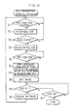
- Fig. 10 is a flow chart illustrating the operation of the video system in normal reproduction mode.
- step 51 when the play key on a keyboard 140 is set on, it is discriminated in step 51 whether or not the sync code 2, 3 or 4 has been input.
- a mode code and a control code following the sync code are fetched in the control area, and the image expander 46 and the like are set to perform an operation associated with compressed image data to be reproduced in step 52.
- step 53 it is discriminated in step 53 whether or not the sync code 1 has been input.
- the sync code 1 has been input, inputting compressed image data for one compression reference period in any video RAM (video RAMs 22a-22c being sequentially used) starts in step 54.
- next step 55 it is discriminated whether or not the sync code 1 related to the next compression reference period has been input.
- the sync code 1 has been input, inputting compressed image data for one compression reference period in the next video RAM starts in step 56.
- the compressed image data written in the video RAM in the previous compression reference period is sequentially read out, then a process of expanding the read data starts in the image expander 46.
- An image is then displayed on a monitor (not shown) connected to the terminals 49R, 49G and 49B.
- step 58 it is discriminated in step 58 whether or not the sync code 1 has been input.
- the sync code 1 has been input, it is discriminated whether or not the stop key on the keyboard 140 is set on in step 59.
- step 57 enters processing for the next compression reference period after the expanding process of the compressed image data written in the video RAMs 22a-22c in the previous compression reference period is completed.
- Intel 82750PB compressing/expanding IC
- compressing/expanding IC may be used as an IC for executing the compressing process in the image compressor 19 and the expanding process in the image expander 46.
- the tape running speed for reproduction in still reproduction mode is the same as the speed in normal reproduction mode.
- Fig. 11 is a flow chart illustrating the operation of the still reproduction (first still reproduction) for sequentially displaying still pictures based on the reference image data through a manual operation.
- step 61 when the first still reproduction is selected through the operation of the keyboard 140, it is discriminated in step 61 whether or not the sync code 2, 3 or 4 has been input.
- a mode code and a control code following the sync code are fetched in the control area, and the image expander 46 and the like are set to perform an operation associated with compressed image data to be reproduced in step 62.
- step 63 It is discriminated in the next step 63 whether or not the sync code 1 has been input.
- reference image data is written in any video RAM (video RAMs 22a-22c being sequentially used) which is selected by the selection switch 45 starts in step 64.
- the reference image data is read out from the video RAM, then is expanded by the image expander 46 to form image data for one frame, and this one-frame image data is stored in a memory provided in the image expander 46.
- the one-frame image data is repeatedly read out from this memory, whereby still picture based on the reference image data are displayed on the monitor connected to the terminals 49R-49B.
- the DAT 130 is set to the play pause.
- step 67 it is discriminated whether or not the play key on the keyboard 140 is set on in step 67.
- this key is on, the play pause of the DAT 130 is released in step 68, then the flow returns to step 61.
- still pictures based on the reference image data in the next compression reference period will be displayed.
- step 67 When the play key is not detected on in step 67, it is discriminated whether or not the stop key on the keyboard 140 is set on in step 69. When the stop key is not on, the flow returns to step 67.
- step 69 When the stop key is judged to be on in step 69, the first still reproduction is terminated.
- Fig. 12 is a flow chart illustrating the operation of the still reproduction (second still reproduction) for sequentially displaying still pictures based on the reference image data after a scene change through a manual operation.
- step 71 when the second still reproduction is selected through the operation of the keyboard 140, it is discriminated in step 71 whether or not the sync code 2, 3 or 4 has been input.
- a mode code and a control code following the sync code are fetched in the control area in step 72.
- control code following the mode code is fetched in step 74.
- the image expander 46 and the like are set to perform an operation associated with the compressed image data to be reproduced.
- step 75 It is discriminated in the next step 75 whether or not the sync code 1 has been input.
- sync code 1 When the sync code 1 has been input, reference image data after the scene change is written in any video RAM (video RAMs 22a-22c being sequentially used) starts in step 76.
- the reference image data is read out from the video RAM, then is expanded by the image expander 46 to form image data for one frame, and this one-frame image data is stored in a memory.
- the one-frame image data is repeatedly read out from this memory, whereby still pictures based on the reference image data immediately after the scene change are displayed on the monitor connected to the terminals 49R-49B.
- the DAT 130 is set to the play pause.
- step 79 it is discriminated whether or not the play key on the keyboard 140 is set on in step 79.
- this key is on, the play pause of the DAT 130 is released in step 80, then the flow returns to step 71.
- step 79 When it is not detected that the play key has been set on in step 79, it is discriminated whether or not the stop key on the keyboard 140 is set on in step 81. When the stop key is not on, the flow returns to step 79.
- step 81 When the stop key is judged to be on in step 81, the second still reproduction is terminated.
- Fig. 13 is a flow chart illustrating the operation of the still reproduction (third still reproduction) for automatically displaying still pictures based on the reference image data at predetermined time intervals one after another. Those steps corresponding to what are shown in Fig. 11 are given the same numerals.
- step 91 After the DAT 130 is set to the play pause state in step 66, it is discriminated in step 91 whether or not a time t has elapsed.
- step 92 it is discriminated in step 92 whether or not the stop key on the keyboard 140 is set on.
- the stop key is not on, the play pause state of the DAT 130 is released in step 68, then the flow returns to step 61.
- step 92 When it is judged in step 92 that the stop key is set on, the third still reproduction is terminated.
- still pictures based on reference image data in each compression reference period are automatically displayed one after another on the monitor at the time interval determined by the time t.
- Fig. 14 is a flow chart illustrating the operation of the still reproduction (fourth still reproduction) for automatically displaying still pictures based on the reference image data immediately after a scene change one after another. Those steps corresponding to what are shown in Fig. 12 are given the same numerals.
- step 94 After the DAT 130 is set to the play pause state in step 78, it is discriminated in step 94 whether or not the time t has elapsed.
- step 95 it is discriminated in step 95 whether or not the stop key on the keyboard 140 is set on.
- the stop key is not on, the play pause state of the DAT 130 is released in step 80, then the flow returns to step 71.
- step 95 When it is judged in step 95 that the stop key is set on, the fourth still reproduction is terminated.
- the next scene change is detected after the time t has elapsed, and still pictures based on reference image data immediately after the scene change are automatically displayed one after another on the monitor.
- the strobe reproduction will now be discussed.
- the tape running speed for reproduction in strobe reproduction mode is the same as the speed in normal reproduction mode.
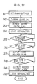
- Fig. 15 is a flow chart illustrating the operation of the strobe reproduction.
- step 151 when the strobe reproduction is selected through the operation of the keyboard 140, it is discriminated in step 151 whether or not the sync code 2, 3 or 4 has been input.
- a mode code and a control code following the sync code are fetched in the control area, and the image expander 46 and the like are set to perform an operation associated with compressed image data to be reproduced in step 152.
- step 153 it is discriminated whether or not the sync code 1 has been input.
- the sync code 1 has been input, inputting compressed image data for one compression reference period in any video RAM (video RAMs 22a-22c being sequentially used) starts in step 154.
- next step 155 it is discriminated whether or not the sync code 1 has been input.
- next step 158 inputting compressed image data for one compression reference period in the next video RAM starts.
- the compressed image data written in the video RAM in the previous compression reference period is sequentially read out, then expanding the read data is executed in the image expander 46.
- a still picture is then displayed on the monitor (not shown) connected to the terminals 49R, 49G and 49B.
- N N + 1 and the difference compressed image data ⁇ cN is read out from the video RAM and subjected to an expanding process in step 160.
- N is the number of frames skipped in strobe display and is preset by the keyboard 140.
- step 161 When N does not equal L x M + 1 in step 161, the flow returns to step 160, and the same processing as described above will be executed. When these values are equal to each other, however, a still picture based on the difference compressed image data ⁇ cN is displayed on the monitor.
- step 163 it is discriminated in step 163 whether or not the sync code 1 has been input.
- L L + 1 in step 164, then the flow returns to step 160 to perform the same processing as described above.
- step 163 When the sync code 1 has been input in step 163, it is discriminated whether or not the stop key on the keyboard 140 is set on in step 165.
- a in Fig. 16 shows reproduced image data in normal reproduction mode, VB1, VB2, ... representing reference image data in the respective compression reference periods which are reproduced at intervals of one second in normal reproduction mode.
- the tape reproducing speed of the DAT 130 is increased to be double the normal speed and the tape is run at this speed for two seconds. Then, the tape reproducing speed is set back to the normal speed, before the next reference image data is reproduced (see B in Fig. 16).
- the tape reproducing speed is set back to the normal speed before reproduction of the reference image data is because the rotary head should be made to properly perform the scanning without crossing the recording tracks.
- reference image data VB1, VB6, VB11, ... are reproduced at intervals of 3.15 seconds as indicated by C in Fig. 16. Those portions indicated by the broken lines are where the rotary head has scanned crossing the recording tracks, and no accurate image data can be obtained.
- the reference image data VB1, VB6, VB11, ... reproduced in the above manner are sequentially written in the video RAMs 22a-22c as indicated by D in Fig. 16.
- the reference image data written in the video RAMs 22a-22c are read out and supplied to the image expander 46 where the data are expanded to form image data for one frame.
- a still picture based on this one-frame image data is kept displayed until image data for one frame is formed based on the next reference image data to be reproduced (see E in Fig. 16).
- Fig. 17 is a flow chart illustrating the operation of this fast-forward reproduction.
- the DAT 130 is controlled by the controller 110 to enter a reproduction mode at the normal speed in step 171.
- step 172 it is discriminated whether or not the sync code 2, 3 or 4 has been input.
- a mode code and a control code following the sync code are fetched in the control area, and the image expander 46 and the like are set to perform an operation associated with compressed image data to be reproduced in step 173.
- step 174 It is discriminated in the next step 174 whether or not the sync code 1 has been input.
- reference image data is written in any video RAM (video RAMs 22a-22c being sequentially used) starts in step 175.
- the reference image data is read out from the video RAM, then is expanded by the image expander 46 to form image data for one frame, and this one-frame image data is stored in a memory.
- the one-frame image data is repeatedly read out from this memory, whereby still pictures based on the reference image data are displayed on the monitor connected to the terminals 49R-49B.
- the DAT 130 is controlled by the controller 110 to double the tape running speed in step 177.
- step 178 It is discriminated in step 178 whether or not two seconds have elapsed. When two seconds have passed, then it is discriminated in step 179 whether or not the stop key on the keyboard 140 is set on. When the stop key is not on, the flow returns to step 171 and the same operation as described above will be repeated. When the stop key is judged to be on, however, the fast-forward reproduction is terminated.
- the fast-forward reproduction about 1.6 times faster than the normal one is realized.
- the fast-forward reproduction at any speed can be realized by adjusting the tape reproducing speed and tape running time.
- a in Fig. 18 shows reproduced image data in normal reproduction mode, CVG1, CVG2, ... representing compressed image data (reference image data VB N and difference compressed image data ⁇ c1- ⁇ c29) in the respective compression reference periods which are sequentially reproduced every one second in normal reproduction mode.
- the DAT 130 is set to the normal speed reproduction state during three compression reference periods, then is set to the play pause state for the same periods. Thereafter, this setting will be repeated.
- compressed image data (CVG1-CVG3) in three compression reference periods are continuously reproduced, then compressed image data (CVG4-CVG6) in the subsequent three compression reference periods are continuously reproduced, as indicated by B in Fig. 18. Thereafter, the reproduction will be repeated.
- the compressed image data CVG1, CVG2, ... in the individual compression reference periods reproduced in the above manner are sequentially written in the video RAMs 22a-22c as indicated by C in Fig. 18.
- the compressed image data written in the video RAMs 22a-22c are read out and supplied to the image expander 46 for data expansion.
- image data VG1, VG2, ... for 30 frames are formed from the compressed image data CVG1, CVG2, ... as in normal reproduction mode.
- a dynamic picture based on image data VG1, VG2, ... is displayed on the monitor in such a manner that the same screen is kept displayed every two frames. That is, the time axis of the dynamic picture based on the image data VG1, VG2, .. is elongated to twice as longer and is displayed accordingly (see D in Fig. 18).
- Fig. 19 is a flow chart illustrating the operation of this slow reproduction.
- the DAT 130 is controlled by the controller 110 to enter a reproduction mode at the normal speed in step 181.
- next step 182 it is discriminated whether or not the sync code 2, 3 or 4 has been input.
- a mode code and a control code following the sync code are fetched in the control area, and the image expander 46 and the like are set to perform an operation associated with compressed image data to be reproduced in step 183.
- N 0 is set in the next step 184, it is discriminated whether or not the sync code 1 has been input in step 185.
- step 189 reading out the compressed image data for three compression reference periods which are to be sequentially written in the video RAMs 22a-22c starts, the expanding process starts in the image expander 46, and a dynamic picture is displayed on the monitor (not shown) connected to the terminals 49R-49B. In this case, the same screen is kept displayed every two frames.
- step 188 inputting compressed image data for one compression reference period in any video RAM (video RAMs 22a-22c being used in order) starts.
- the DAT 130 is controlled by the controller 110 to enter the play pause mode in step 192.
- image data for three consecutive compression reference periods have been written in the video RAMs 22a-22c.
- a time T3 equal to the three compression reference periods has elapsed.
- the time is not set to three seconds because the three compression reference periods may become shorter than three seconds when there is a scene change.
- the foregoing description has been given with reference to the case where the normal-speed reproduction mode for three compression reference periods, and the play pause mode for the same periods are repeated.
- the "three" compression reference periods are determined in association with the three video RAMs 22a-22c, and this number is in no way restrictive. For instance, one compression reference period as well as two compression reference periods may be employed.
- the slow reproduction at an arbitrary speed can be realized by adjusting the pause duration. For instance, if the pause duration is set to twice as longer than the compression reference period in the case of the normal-speed reproduction and the same screen is kept displayed every three frames, the time axis of a dynamic picture displayed on the monitor becomes three times longer, thereby realizing a slow reproduction at a 1/3 of the normal speed.
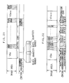
- record data is structured as shown in Fig. 20.
- the data structure in the control area is altered as compared with the one shown in Fig. 4.
- sync codes 1B-4B and mode codes 1B-4B are allocated at locations (the area for the control code in Fig. 4) symmetrical to the sync codes 1A-4A and mode codes 1A-4A.
- the sync codes 1A-4A and mode codes 1A-4A can be detected at the time of normal reproduction, while the sync codes 1B-4B and mode codes 1B-4B can be detected at the time of reverse reproduction.
- mode codes 1A-4A are allocated data corresponding to the next compression reference period in the normal reproducing direction as in the case of the mode code in Fig 4.
- the mode codes 1B-4B are allocated data corresponding to the next compression reference period in the reverse reproducing direction.
- the data includes data about a change in the amount of the difference compressed image data ⁇ c1- ⁇ c29 in the next compression period, data indicating if the period is immediately before the occurrence of a scene change, and data about the period in the last case, in addition to the same data allocated in the mode codes 1A-4A.
- the amount of difference compressed image data ⁇ c1- ⁇ c29 is fixed and the allocated position of each difference compressed image data is therefore fixed.
- the amount of difference compressed image data ⁇ c1- ⁇ c29 may be changed to improve the quality of image data in accordance with the status of an image. (This case will be described later.)
- the allocated position of each difference compressed image data varies. It is therefore necessary to consider the amount of the individual difference compressed image data ⁇ c1- ⁇ c29 in order to control the addresses of the video RAMs 22a-22c to write reproduced data at the same addresses as used in normal reproduction mode from the reverse direction in reverse reproduction mode.
- the record data is structured as shown in Fig. 20 so that reproduction is effected, using sync the codes 1A-4A and mode codes 1A-4A in normal reproduction mode.
- the reproduction operation is executed using the sync codes 1B-4B and mode codes 1B-4B. Based on data which indicates a change in the amount of difference compressed image data allocated in the mode codes 1B-4B, addresses of the video RAMs 22a-22c are controlled, and reproduced data is written, from the reverse direction, at the same address as is done in normal reproduction mode.
- the subsequent expansion process by the image expander 46 is also carried out in the same manner as in normal reproduction mode, and a reverse reproduced screen is displayed on the monitor.
- Fig. 21 illustrates an example for changing the amount of data.
- the area for the reference image data has 276480 bits as in the case where the amount of the above data is fixed.
- the image area of a single compression reference period is 1152000 bits as described before, and the remaining 32320 bits are used to adjust the fixed length.
- the reference image data is allocated in the area for the reference image data in the same manner as done in the case where the amount of the above data is fixed.
- the difference compressed image data ⁇ c1- ⁇ c29 are basically allocated in the areas B1-B29, respectively.
- the number of bit showing differential data become large and the total amount of data is increased and it is conceived that the difference compressed image data cannot be held in the area of 27200 bits. In this case, two or more areas are used.
- Allocated in a block number portion are data 1-29 which indicate the difference compressed image data using two or more areas.
- Data representing the number of the areas to be used is allocated in a quantity portion (for example, "0" for two areas, and "1" for three areas).
- the image data ⁇ c1- ⁇ c4 are allocated in the areas B1-B4 respectively, the image data ⁇ c5 in the areas B5 and B6, the image data ⁇ c6- ⁇ c19 in the respective areas B7-B20, the image data ⁇ c20 in the areas B21 and B22, and the image data ⁇ c21- ⁇ c29 in the respective areas B23-B31.
- the above data is sent to the controller 110 in the reproduction mode, and the addresses of the individual video RAMs 22a-22c are controlled, so that the correct signal reproducing process will be performed the same as when the amount of every difference compressed image data is fixed.
- Fig. 22 illustrates another example for changing the data amount.
- 276480 bits are given as the area for the reference image data, the same as a case of the data with the fixed amount.
- the areas for the difference compressed image data ⁇ c1- ⁇ c29 are respectively provided with bits according to the amount of their data.
- the address information of the video RAMs 22a-22c to be written in the normal reproduction is allocated, for example, as 18-bit data, in the control area.
- This address information is read by the controller 110 in the normal reproduction mode, to control the addresses of the video RAMs 22a-22c, and the correct signal reproducing system is performed in the same manner as the case of the amount of every difference compressed image data described above is fixed.
- the difference compressed image data whose amount corresponds to the image condition can be recorded and reproduced, improving the quality of the image data.
- the example shown in Fig. 22 is superior to the one shown in Fig. 21 in terms of effective use of the image area, while the example in Fig. 21 is superior in terms of effective use of the control area.
- the time code may be allocated in the control area of the record data.
- the sync code portion consists of 64 bits in the above example. In this example, however, the sync code portion is given 48 bits with a 16-bit time code portion provided between the sync code portion and mode code portion, as shown in, for example, Fig. 23.
- time code portions may be provided in a single compression reference period (one second). The same data is allocated in the four time code portions.
- 16-bit data of the time code portion shows, for example, the absolute time (second).
- BCD Binary Coded Decimal
- the time codes recorded in this way are fetched to be used for searching, display of the amount of remaining tape, and control for positional adjustment in editing mode.
- time codes ensures a search with one-second precision; however, the use of the sync codes 1-4 of different types can ensure a search of 1/4-second precision.
- the structure of the time code, its allocated position, and the number of bits of the time code are not limited to those exemplified in Fig. 23.
- "hour, minute, second" can be represented as the structure of the time code.
- Fig. 24 illustrates the structure for digital-dubbing with the two DATs.
- Reference numeral "201" denotes the DAT on the master side and "202 the DAT on the slave side. These DATs 201 and 202 are connected to each other through a digital audio interface DAI.
- the DAT 201 supplies a sync signal such as a bit clock BCK to the DAT 202 for synchronization therebetween.
- the DAT 201 also sends various control flags to the DAT 202 to control the DAT 202.
- the DAT 201 includes at least a video reproduction circuit of the signal processor shown in Figs. 1A and 1B, and the video-out terminal is connected to a monitor 203.
- the DAT 201 has a dubbing start key 201a, a dubbing stop key 201b, and dubbing-time set key 201c, besides the normal record and play keys (not shown).
- the DAT 201 When the dubbing start key 201a is pressed for dubbing operation, with the DAT 201 in normal reproduction mode and a dynamic picture displayed in the monitor 203, the DAT 201 supplies the record pause flag to the DAT 202 in step 211 to set the DAT 202 in the record pause state.
- step 212 the frame image data at the time of the dubbing start key 201a set on is repeatedly read from the memory of the image expander 46 one after another, to display a still picture on the monitor 203.
- the DAT 201 starts the reverse reproduction in step 213.
- the still picture remains on the monitor even during the reverse reproduction.
- step 214 it is determined in step 214 if the sync code 1B has been input.
- step 215 it is determined in step 215 whether the sync code 4B is received.
- step 216 it is determined in step 216 if the sync code 3B has been input.
- step 216 When it is judged in step 216 that the sync code 3B has been received, the DAT 201 stops the reverse reproduction in step 217.
- step 218 the DAT 201 sends a pause release flag to the DAT 202 to set the DAT 202 in a record state.
- the DAT 201 starts normal reproduction in step 219, and reproduced data is sent through the digital audio interface DAI to the DAT 202, thus starting recording.
- step 220 the dynamic picture is displayed on the monitor 203.
- step 221 it is determined in step 221 whether or not the dubbing stop key 201b is set on.
- step 22 it is determined in step 22 if the sync code 1A has been input.
- step 223 it is determined in step 223 if the sync code 2A has been input.
- the DAT 201 sends a record stop flag to the DAT 202 in step 224, so that the DAT 202 is set in a stop state, thus stopping recording.
- the DAT 201 stops reproduction in step 225, terminating the dubbing operation.
- Fig. 26 An example of dubbing for a certain period of time while monitoring the reproduced screen will now be explained referring to the flow chart in Fig. 26.
- This dubbing can be applied to both cases of recording data in the structures shown in Figs. 4 and 20.
- the sync codes 1-4 in Fig. 26 correspond to the sync codes 1A-4A in Fig. 20.
- the DAT 201 supplies a record pause flag to the DAT 202 in step 231 to set the DAT 202 in a record pause state.
- step 232 it is determined in step 232 whether or riot the sync code 3 has been input.
- the DAT 201 sends a pause release flag to the DAT 202 in step 233 to set the DAT 202 in a record state. This starts recording the reproduced data which is sent from the DAT 201 through the digital audio interface DAI.
- step 234 It is determined in step 234 if the dubbing stop key 201b is set on. When the dubbing stop key 201b is set on, it is determined in step 235 whether or not the sync code 1 has been received. When the sync code 1 is received, it is determined in step 236 whether the sync code 2 has been input.
- the DAT 201 supplies the record stop flag to the DAT 202 in step 237, so that the DAT is stopped to stop recording.
- the DAT 201 stops reproduction in step 238, terminating the dubbing operation.
- the recording is also performed from the portion immediately before the sync code 4 up to the portion immediately after the sync code 2. Therefore, it is possible to efficiently record only the required portion.
- a dubbing-period set key 201c is set on to set the dubbing start time and dubbing end time.
- the time is input in terms of "hour, minute, second.”
- the DAT 201 supplies the record pause flag to the DAT 202 in step 243 to set the DAT 202 in a record pause state.
- step 244 the DAT 201 starts reproduction in step 244. It is determined in step 245 if the time code to be detected from the control area of the reproduced data indicates "dubbing start time - 1 sec". When the time code is "dubbing start time - 1 sec", it is determined in step 246 whether or not the sync code 3 has been input.
- the DAT 201 sends a pause release flag to the DAT 202 in step 247 to set the DAT 202 in a record state. This starts recording the reproduced data which is sent from the DAT 201 through the digital audio interface DAI.
- step 248 It is then determined in step 248 if the time code to be detected from the control area of the reproduced data indicates "dubbing end time + 1 sec".
- the DAT 201 sends the record stop flag to the DAT 202 in step 249 so that the DAT 202 is set in a stop status to stop recording.
- the DAT 201 stops the reproduction in step 250, terminating the dubbing operation.
- the dubbing example shown in Fig. 27 makes it possible to perform automatic dubbing in a set period of time. Under the control based on the sync codes, the recording is done from the portion immediately before the sync code 4 up to the portion immediately after the sync code 2. Therefore, it is possible to efficiently record only the required portion.
- Fig. 24 illustrates the DAT 201 on the side of the master operating keys
- the DAT 202 on the slave side can be also structured to have keys for operation.
- the above described examples are for recording only the dynamic pictures as image data.
- the image data for the still pictures is also possibly recorded by switching.
- the image data S1, S2, ... for still pictures are recorded after some difference compressed image data for dynamic pictures is allocated, as shown in Fig. 28.
- the image data of the individual frames, which the RAMs 17a-17c receive one after another, are read out and allocated as still picture data in the data area for recording.
- the image data S1, S2, ... for still pictures can be compressed by the image compressor 19 to be identical to the reference image data VB N for dynamic pictures. Further, the image data for still pictures can be recorded in high quality by enlarging the area for data recording with a low compression ratio or without compression.
- the signal processor in Figs. 1A and 1B include the RAMs 17a-17c for three frames, even if the image data for still pictures is made to have high quality, it is still possible to effect recording for three consecutive frames or so-called three continuous shots.
- the sync code portions and mode code portions are provided in the control area corresponding to the point immediately before the image data S1, S2, ... for still pictures.
- the data indicating the still picture mode is allocated in each mode code portion.
- control can be effected so as to shift from reproduction of dynamic pictures to reproduction of still pictures, based on the data which indicates the still picture mode and is detected from the control area of the reproduced data.
- image data S1, S2, ... for still pictures are consecutively arranged in Fig. 28, these data may be also arranged at predetermined intervals.
- 12 bits are for the image area, 3 bits for the audio area, and one bit for the control area.
- the number of bits and the allocation are not limited to this particular example.
- video signals of the NTSC system are treated as video signal in the above embodiment
- video signals of other systems such as the PAL system and the SECAM system
- some change should be made according to the number of frames. For example, in the case of 25 frames per sec, there are 24 pieces of difference compressed image data ⁇ c1- ⁇ c24.
- the DAT serves as the recording and reproducing apparatus; however, this embodiment can also be applied to the case involving a disk type recording medium or an optical recording medium.
- video signals for dynamic pictures as well as audio signals can be digitally recorded simultaneously, the former signals through compression, providing a very efficient recording and reproducing apparatus, such as a DAT.
- Recorded in the control area are data concerning digital signals allocated in the image area or the audio area, i.e., compression information and signal mode information.
- compression information i.e., compression information and signal mode information.
- each compression reference period In the control area in each compression reference period are allocated data concerning digital signals in the image area or the audio area in the succeeding compression reference periods. It is therefore possible to control the signal reproducing system before processing the digital signals in the image area or the audio area in every compression reference period in reproduction mode.
- the same data is allocated in one compression reference period several times at predetermined intervals. When data reproduction starts from any position, the data concerning the digital signals can efficiently be fetched to control the signal reproducing system smoothly.
- the signal recording process is reset, the reference image data is prepared, then, the difference image data is prepared based on this reference image data.
- the amount of the difference image data does not increase very much even when the scene change occurs, and is held in a predetermined image area. In other words, the desirable compression process can always be done.
- the data for indicating the presence of the scene change is allocated in the compression reference period in the control area immediately before the scene change, it is possible to select only the image immediately after the scene change and reproduce it, based on the data in reproduction mode, for example.
- the timing for the reproduced image always matches with the timing for the reproduced sounds, thereby avoiding a time lag between the image and the associated sounds.
- predetermined image data to be reproduced is expanded, and expanded image data for one screen is repeatedly output, still pictures based on predetermined reference image data, for example, in each compression reference period or reference image data in the compression reference period immediately after occurrence of a scene change can be manually or automatically displayed one after another on the monitor.
- control area in each compression reference period are allocated first data and second data concerning digital video signals to be allocated in the image areas in immediately before and immediately after compression reference periods. Further, in both normal reproduction mode and reverse reproduction mode, the operation of the signal reproducing system can be controlled before processing the digital video signal to be reproduced. Therefore, the normal reproduction as well as reverse reproduction can be performed.
- compressed digital video signals for multiple screens are stored at the same addresses in the reverse reproduction mode as done in the normal reproduction mode.
- a digital video signal is allocated in the image area in each compression reference period in such a manner that reference image data for one screen is allocated first, then difference compressed image data for multiple screens are allocated, therefore, signal reading from the memory and expanding the read-out signal can be executed in the same manner in normal reproduction mode as in reverse reproduction mode. The reverse reproduction can therefore be realized easily.
- this time code when fetched at the time of reproduction can be effectively used to control searching, displaying the amount of remaining tape, positional adjustment at the time of edition, and the like.
- reproduction at the normal speed and reproduction at a predetermined fast speed can alternately be performed, predetermined image data to be reproduced at the normal speed can be expanded, and expanded image data for one screen can be repeatedly output.
- fast-forwarding images can be displayed on the monitor.
- the fast-forwarding images will not have horizontal noise bars, thus providing images that can be viewed very easily.
- data indicating such a change is allocated in the control area. Based on this data, therefore, the addresses of the memory for storing reference image data and difference compressed image data are controlled, the difference compressed image data for each screen can be stored at the associated address. This can ensure accurate signal reproduction as in the case where the area is fixed.
- the normal reproduction mode and play pause mode can alternately be repeated, so that image data for each screen expanded after reproduction in normal reproduction mode can be repeatedly output by the number of times associated with the play pause period. Therefore, the time axis of a dynamic picture to be displayed on the monitor is expanded in accordance with the play pause period, thus ensuring slow reproduction at a predetermined speed.
- the sync codes detected from the control area of a signal to be reproduced from one recording medium can serve to control the period for data recording on another recording medium.
- operational control can be effected in such a way as to record data starting with a point slightly before a certain compression reference period up to a point slight after another compression reference period. In this manner, the necessary portion can efficiently dubbed.
- time code detected from the control area of a signal to be reproduced from one recording medium can serve to control the time for data recording on another recording medium, dubbing in the period set by the dubbing set key can automatically be performed.
- a video signal for a dynamic picture or a still picture as well as an audio signal can simultaneously be recorded or reproduced.
- Selectively switching the image area between the dynamic picture area and still picture area can ensure recording/reproducing of a digital video signal for a dynamic picture and a digital video signal for a still picture.
- the image area can be set to the still picture area to record or reproduce that digital video signal which provides a high-quality still picture.
- control area e.g., the mode code area
Applications Claiming Priority (2)
| Application Number | Priority Date | Filing Date | Title |
|---|---|---|---|
| JP2156726A JPH0447876A (ja) | 1990-06-15 | 1990-06-15 | ディジタル信号の記録再生方式 |
| JP156726/90 | 1990-06-15 |
Publications (3)
| Publication Number | Publication Date |
|---|---|
| EP0461649A2 true EP0461649A2 (fr) | 1991-12-18 |
| EP0461649A3 EP0461649A3 (en) | 1993-01-20 |
| EP0461649B1 EP0461649B1 (fr) | 1997-01-29 |
Family
ID=15633991
Family Applications (1)
| Application Number | Title | Priority Date | Filing Date |
|---|---|---|---|
| EP19910109707 Expired - Lifetime EP0461649B1 (fr) | 1990-06-15 | 1991-06-13 | Méthode et appareil d'enregistrement et de reproduction |
Country Status (4)
| Country | Link |
|---|---|
| US (1) | US5270828A (fr) |
| EP (1) | EP0461649B1 (fr) |
| JP (1) | JPH0447876A (fr) |
| DE (1) | DE69124423T2 (fr) |
Cited By (5)
| Publication number | Priority date | Publication date | Assignee | Title |
|---|---|---|---|---|
| EP0558306A2 (fr) * | 1992-02-25 | 1993-09-01 | Mitsubishi Denki Kabushiki Kaisha | Appareil d'enregistrement et de reproduction |
| EP0620683A2 (fr) * | 1993-04-16 | 1994-10-19 | Lg Electronics Inc. | Appareil pour commander l'enregistrement et la reproduction dans un enregistreur à bande vidéo numérique |
| EP0651391A2 (fr) * | 1993-10-29 | 1995-05-03 | Kabushiki Kaisha Toshiba | Appareil de reproduction avec fonction de recherche |
| US5510899A (en) * | 1993-04-02 | 1996-04-23 | Goldstar Co., Ltd. | Method of multi-speed recording-reproducing a video signal in digital video cassette recorder |
| CN1069009C (zh) * | 1995-12-27 | 2001-07-25 | 三星电子株式会社 | 视频信号处理系统中处理非标准同步信号的装置和方法 |
Families Citing this family (29)
| Publication number | Priority date | Publication date | Assignee | Title |
|---|---|---|---|---|
| JPH04332960A (ja) * | 1991-05-07 | 1992-11-19 | Sanyo Electric Co Ltd | ディジタル高速ダビング回路 |
| US5774624A (en) | 1991-12-25 | 1998-06-30 | Canon Kabushiki Kaisha | Image signal recording apparatus having intrapicture and interpicture coding modes |
| JP3184011B2 (ja) * | 1992-07-20 | 2001-07-09 | 株式会社東芝 | 帯域圧縮信号処理装置 |
| EP0790743B1 (fr) * | 1993-09-16 | 1998-10-28 | Kabushiki Kaisha Toshiba | Appareil de synchronisation de signaux vidéo et audio comprimés |
| EP0836192A1 (fr) * | 1993-10-29 | 1998-04-15 | Kabushiki Kaisha Toshiba | Support d'enregistrement de plusieurs scènes, et méthode et appareil de reproduction de données de celui-ci |
| US5764846A (en) * | 1993-10-29 | 1998-06-09 | Kabushiki Kaisha Toshiba | Multi-scene recording medium and apparatus for reproducing data therefrom |
| DE69318038T2 (de) * | 1993-10-29 | 1998-10-29 | Toshiba Kawasaki Kk | Aufzeichnungsmedium, das verschiedene sprachen verarbeiten kann und wiedergabevorrichtung |
| US5850500A (en) * | 1995-06-28 | 1998-12-15 | Kabushiki Kaisha Toshiba | Recording medium comprising a plurality of different languages which are selectable independently of each other |
| EP0664646B1 (fr) * | 1994-01-20 | 2007-08-08 | Sony Corporation | Appareils d'enregistrement et de reproduction de signaux audio et vidéo numériques |
| JP3320199B2 (ja) * | 1994-05-25 | 2002-09-03 | キヤノン株式会社 | 画像再生装置 |
| US5809201A (en) * | 1994-06-24 | 1998-09-15 | Mitsubishi Denki Kabushiki Kaisha | Specially formatted optical disk and method of playback |
| JP3250588B2 (ja) * | 1994-07-12 | 2002-01-28 | ソニー株式会社 | データ再生装置 |
| US5778142A (en) * | 1994-11-24 | 1998-07-07 | Kabushiki Kaisha Toshiba | Large capacity recording medium, method and apparatus for reproducing data from a large-capacity recording medium, and method and apparatus for recording data on a large-capacity recording medium |
| US6009202A (en) * | 1994-12-28 | 1999-12-28 | Kabushiki Kaisha Toshiba | Image information encoding/decoding system |
| US5721720A (en) * | 1994-12-28 | 1998-02-24 | Kabushiki Kaisha Toshiba | Optical recording medium recording pixel data as a compressed unit data block |
| CA2168327C (fr) * | 1995-01-30 | 2000-04-11 | Shinichi Kikuchi | Support d'enregistrement de donnees comportant des donnees de navigation, methode et appareil d'enregistrement de telles donnees et systeme de transmission de ces donnees via une route de communication utilisant les donnees de navigation a cette fin |
| US6002832A (en) * | 1995-02-09 | 1999-12-14 | Matsushita Electric Industrial Co., Ltd. | Apparatus and method for recording and reproducing data |
| JPH08275170A (ja) * | 1995-03-30 | 1996-10-18 | Canon Inc | 画像処理装置 |
| US5703997A (en) * | 1995-04-14 | 1997-12-30 | Kabushiki Kaisha Toshiba | Data recording medium having reproduction timing information, and system for reproducing record data by using the reproduction timing information |
| WO1996032720A1 (fr) * | 1995-04-14 | 1996-10-17 | Kabushiki Kaisha Toshiba | Support d'enregistrement, dispositif et procede pour l'enregistrement des donnees sur le support, et dispositif et procede pour la reproduction des donnees a partir du support |
| EP0737979B1 (fr) * | 1995-04-14 | 2006-10-25 | Kabushiki Kaisha Toshiba | Appareil de reproduction d'un support d'enregistrement |
| US5838874A (en) * | 1995-05-08 | 1998-11-17 | Kabushiki Kaisha Toshiba | Audiovisual encoding system with a reduced number of audio encoders |
| US5724475A (en) * | 1995-05-18 | 1998-03-03 | Kirsten; Jeff P. | Compressed digital video reload and playback system |
| US5845046A (en) * | 1995-06-15 | 1998-12-01 | Kabushiki Kaisha Toshiba | Multi-scene recording medium and apparatus for producing data therefrom |
| US6014491A (en) * | 1997-03-04 | 2000-01-11 | Parsec Sight/Sound, Inc. | Method and system for manipulation of audio or video signals |
| US6721491B1 (en) * | 1999-12-22 | 2004-04-13 | Sightsound Technologies, Inc. | Method and system for manipulation of audio or video signals |
| CA2275401C (fr) * | 1997-10-28 | 2007-03-06 | Sony Corporation | Appareil d'enregistrement de donnees, procede d'enregistrement de donnees, appareil d'edition de donnees et procede d'edition de donnees |
| US6925180B2 (en) * | 2001-09-27 | 2005-08-02 | Sony Corporation | PC card recorder |
| US20040125707A1 (en) * | 2002-04-05 | 2004-07-01 | Rodolfo Vargas | Retrieving content of various types with a conversion device attachable to audio outputs of an audio CD player |
Citations (7)
| Publication number | Priority date | Publication date | Assignee | Title |
|---|---|---|---|---|
| JPS62154374A (ja) * | 1985-12-27 | 1987-07-09 | Matsushita Electric Ind Co Ltd | デ−タ再生装置 |
| US4710826A (en) * | 1985-06-18 | 1987-12-01 | Casio Computer Co., Ltd. | Apparatus with liquid crystal display panel, for recording/playing back television signal by utilizing digital audio tape recorder system |
| JPH02123565A (ja) * | 1988-11-02 | 1990-05-11 | Matsushita Electric Ind Co Ltd | 記録再生装置 |
| US4931879A (en) * | 1987-04-30 | 1990-06-05 | Nec Corp. | Image processing system for recording or reproducing an image signal sequence which has been encoded by employing two predictive coding methods and combining the results of those methods |
| EP0406595A2 (fr) * | 1989-06-13 | 1991-01-09 | Aiwa Co., Ltd. | Procédé et dispositif d'enregistrement et de reproduction d'un signal numérique |
| JPH0447873A (ja) * | 1990-06-15 | 1992-02-18 | Aiwa Co Ltd | ダビング装置 |
| JPH0447888A (ja) * | 1990-06-15 | 1992-02-18 | Aiwa Co Ltd | ディジタル信号の記録再生方式 |
Family Cites Families (16)
| Publication number | Priority date | Publication date | Assignee | Title |
|---|---|---|---|---|
| DE2645747C2 (de) * | 1976-10-09 | 1984-02-16 | Robert Bosch Gmbh, 7000 Stuttgart | Verfahren zur Wiedergabe von einzelnen Bildern von auf bandförmigen Trägern aufgezeichneten Fernsehsignalen |
| JPS58218004A (ja) * | 1982-06-10 | 1983-12-19 | Fuji Photo Film Co Ltd | 電子スチルカメラの音声記録方法および装置 |
| US4692816A (en) * | 1983-07-08 | 1987-09-08 | Victor Company Of Japan Ltd. | Digital data transmitting system for transmitting digital data a number of times depending on an information content of the digital data |
| JPS60157372A (ja) * | 1984-01-26 | 1985-08-17 | Nippon Kogaku Kk <Nikon> | 画像処理システムの枠検出装置 |
| JPS60223275A (ja) * | 1984-04-18 | 1985-11-07 | Fuji Photo Film Co Ltd | デイジタルビデオ信号記録方法 |
| JPS6139783A (ja) * | 1984-07-31 | 1986-02-25 | Matsushita Electric Ind Co Ltd | 記録再生装置 |
| JPS61156979A (ja) * | 1984-12-27 | 1986-07-16 | Sony Corp | 録音機能付き電子スチルカメラ装置 |
| JP2519408B2 (ja) * | 1985-02-12 | 1996-07-31 | キヤノン株式会社 | 記録装置 |
| US4835623A (en) * | 1985-04-05 | 1989-05-30 | Pioneer Electronic Corporation | System for playing video information recording disks, capable of special playback mode operation with a CLV disk |
| JPH0636606B2 (ja) * | 1985-06-19 | 1994-05-11 | ソニー株式会社 | 磁気記録再生装置 |
| DE3783248T2 (de) * | 1986-03-06 | 1993-04-29 | Pioneer Electronic Corp | Verfahren und vorrichtung zur wiedergabe von auf eine speicherdiskette gespeicherte daten. |
| JPH0720228B2 (ja) * | 1987-04-30 | 1995-03-06 | 日本電気株式会社 | 画像の圧縮記録システム |
| US5032927A (en) * | 1988-03-01 | 1991-07-16 | Fuji Photo Film Co., Ltd. | Image signal recording apparatus capable of recording compressed image data together with audio data |
| DE68923472T2 (de) * | 1988-04-08 | 1995-12-07 | Fuji Photo Film Co Ltd | Elektronische Standbildkamera mit der Fähigkeit ein Aufzeichnungsmittel auszuwählen. |
| JPH0828066B2 (ja) * | 1988-08-31 | 1996-03-21 | 松下電器産業株式会社 | 再生装置 |
| JP2797404B2 (ja) * | 1989-04-20 | 1998-09-17 | ソニー株式会社 | 動画像データの記録方式 |
-
1990
- 1990-06-15 JP JP2156726A patent/JPH0447876A/ja active Pending
-
1991
- 1991-06-04 US US07/710,136 patent/US5270828A/en not_active Expired - Fee Related
- 1991-06-13 DE DE1991624423 patent/DE69124423T2/de not_active Expired - Fee Related
- 1991-06-13 EP EP19910109707 patent/EP0461649B1/fr not_active Expired - Lifetime
Patent Citations (7)
| Publication number | Priority date | Publication date | Assignee | Title |
|---|---|---|---|---|
| US4710826A (en) * | 1985-06-18 | 1987-12-01 | Casio Computer Co., Ltd. | Apparatus with liquid crystal display panel, for recording/playing back television signal by utilizing digital audio tape recorder system |
| JPS62154374A (ja) * | 1985-12-27 | 1987-07-09 | Matsushita Electric Ind Co Ltd | デ−タ再生装置 |
| US4931879A (en) * | 1987-04-30 | 1990-06-05 | Nec Corp. | Image processing system for recording or reproducing an image signal sequence which has been encoded by employing two predictive coding methods and combining the results of those methods |
| JPH02123565A (ja) * | 1988-11-02 | 1990-05-11 | Matsushita Electric Ind Co Ltd | 記録再生装置 |
| EP0406595A2 (fr) * | 1989-06-13 | 1991-01-09 | Aiwa Co., Ltd. | Procédé et dispositif d'enregistrement et de reproduction d'un signal numérique |
| JPH0447873A (ja) * | 1990-06-15 | 1992-02-18 | Aiwa Co Ltd | ダビング装置 |
| JPH0447888A (ja) * | 1990-06-15 | 1992-02-18 | Aiwa Co Ltd | ディジタル信号の記録再生方式 |
Non-Patent Citations (3)
| Title |
|---|
| PATENT ABSTRACTS OF JAPAN vol. 011, no. 389 (P-648)19 December 1987 & JP-A-62 154374 ( MATSUSHITA ELECTRIC INDUSTRIAL CO. LTD ) 9 July 1987 * |
| PATENT ABSTRACTS OF JAPAN vol. 016, no. 236 (E-1210)29 May 1992 & JP-A-04 047873 ( AIWA CO., LTD ) 18 February 1992 * |
| PATENT ABSTRACTS OF JAPAN vol. 016, no. 236 (E-1210)29 May 1992 & JP-A-04 047888 ( AIWA CO., LTD ) 18 February 1992 * |
Cited By (18)
| Publication number | Priority date | Publication date | Assignee | Title |
|---|---|---|---|---|
| EP0558306A2 (fr) * | 1992-02-25 | 1993-09-01 | Mitsubishi Denki Kabushiki Kaisha | Appareil d'enregistrement et de reproduction |
| EP0558306A3 (fr) * | 1992-02-25 | 1995-03-01 | Mitsubishi Electric Corp | |
| US5546191A (en) * | 1992-02-25 | 1996-08-13 | Mitsubishi Denki Kabushiki Kaisha | Recording and reproducing apparatus |
| US5510899A (en) * | 1993-04-02 | 1996-04-23 | Goldstar Co., Ltd. | Method of multi-speed recording-reproducing a video signal in digital video cassette recorder |
| USRE41125E1 (en) * | 1993-04-16 | 2010-02-16 | Lg Electronics Inc. | Apparatus and method for controlling recording and reproduction in digital recording medium |
| USRE41820E1 (en) | 1993-04-16 | 2010-10-12 | Lg Electronics Inc. | Apparatus, method and storage medium for recording and/or reproducing digital data using relative position data |
| USRE42795E1 (en) | 1993-04-16 | 2011-10-04 | Lg Electronics Inc. | Apparatus and method for recording or reproducing digital data using speed information |
| US5587789A (en) * | 1993-04-16 | 1996-12-24 | Goldstar Co. Ltd. | Apparatus and method for controlling recording and reproduction in digital video cassette tape recorder |
| USRE42679E1 (en) | 1993-04-16 | 2011-09-06 | Lg Electronics Inc. | Apparatus and method for recording or reproducing digital data using speed information |
| USRE41971E1 (en) | 1993-04-16 | 2010-11-30 | Lg Electronics Inc. | Apparatus, method and storage medium for recording and/or reproducing digital data using relative position data |
| USRE38868E1 (en) * | 1993-04-16 | 2005-11-08 | Lg Electronics Inc. | Apparatus and method for controlling recording and reproduction in digital video cassette tape recorder |
| USRE41042E1 (en) * | 1993-04-16 | 2009-12-15 | Lg Electronics Inc. | Apparatus and method for recording or reproducing digital data using timing information and speed information |
| EP0620683A2 (fr) * | 1993-04-16 | 1994-10-19 | Lg Electronics Inc. | Appareil pour commander l'enregistrement et la reproduction dans un enregistreur à bande vidéo numérique |
| USRE41611E1 (en) | 1993-04-16 | 2010-08-31 | Lg Electronics Inc. | Apparatus and method for recording or reproducing digital data using speed information |
| EP0620683A3 (fr) * | 1993-04-16 | 1995-05-31 | Gold Star Co | Appareil pour commander l'enregistrement et la reproduction dans un enregistreur à bande vidéo numérique. |
| EP0651391A3 (fr) * | 1993-10-29 | 1997-02-05 | Tokyo Shibaura Electric Co | Appareil de reproduction avec fonction de recherche. |
| EP0651391A2 (fr) * | 1993-10-29 | 1995-05-03 | Kabushiki Kaisha Toshiba | Appareil de reproduction avec fonction de recherche |
| CN1069009C (zh) * | 1995-12-27 | 2001-07-25 | 三星电子株式会社 | 视频信号处理系统中处理非标准同步信号的装置和方法 |
Also Published As
| Publication number | Publication date |
|---|---|
| JPH0447876A (ja) | 1992-02-18 |
| EP0461649A3 (en) | 1993-01-20 |
| EP0461649B1 (fr) | 1997-01-29 |
| DE69124423D1 (de) | 1997-03-13 |
| DE69124423T2 (de) | 1997-08-21 |
| US5270828A (en) | 1993-12-14 |
Similar Documents
| Publication | Publication Date | Title |
|---|---|---|
| EP0461649B1 (fr) | Méthode et appareil d'enregistrement et de reproduction | |
| EP0253192B1 (fr) | Appareil d'enregistrement et de reproduction magnétique | |
| US5774192A (en) | Apparatus for recording/reproducing video data to/from a solid-state | |
| US6334023B1 (en) | Method of and arrangement for recording and reproducing video images | |
| US5548451A (en) | Recording and reproducing method and apparatus for a digital audio signal and a digital video signal | |
| JP2711172B2 (ja) | ディジタル信号の記録再生方式 | |
| JP2711171B2 (ja) | ディジタル信号の記録再生方式 | |
| JP3004319B2 (ja) | ディジタル信号の記録再生方式 | |
| JP2726327B2 (ja) | ディジタル信号の記録再生方式および再生装置 | |
| JP2988968B2 (ja) | ディジタル信号の再生装置 | |
| JP2711173B2 (ja) | ディジタル信号の記録再生方式 | |
| JP3441004B2 (ja) | 磁気テープおよびデジタル記録再生装置 | |
| JP3104415B2 (ja) | 情報記録再生装置 | |
| JP3441795B2 (ja) | 再生装置 | |
| US5315446A (en) | Recording and reproducing method and apparatus for a digital audio signal and a reversed bit order digital video | |
| JPH0447877A (ja) | ディジタル信号の記録再生方式 | |
| JPH0447880A (ja) | ディジタル信号の記録再生方式 | |
| JPH02149975A (ja) | 画像信号および音声信号のディジタルオーディオテープ記録方式 | |
| JPH0447873A (ja) | ダビング装置 | |
| JPH02149991A (ja) | 画像信号および音声信号のディジタルオーディオテープファイル編集方法 | |
| JPH0447881A (ja) | ディジタル信号の再生装置 | |
| JPH0447884A (ja) | ディジタル信号の記録再生方式 | |
| JP2786481B2 (ja) | ディジタル信号の信号処理装置 | |
| CA2043979A1 (fr) | Methode et appareil d'enregistrement et de lecture | |
| JPH0447882A (ja) | ディジタル信号の再生装置 |
Legal Events
| Date | Code | Title | Description |
|---|---|---|---|
| PUAI | Public reference made under article 153(3) epc to a published international application that has entered the european phase |
Free format text: ORIGINAL CODE: 0009012 |
|
| AK | Designated contracting states |
Kind code of ref document: A2 Designated state(s): BE DE FR GB IT NL |
|
| PUAL | Search report despatched |
Free format text: ORIGINAL CODE: 0009013 |
|
| AK | Designated contracting states |
Kind code of ref document: A3 Designated state(s): BE DE FR GB IT NL |
|
| 17P | Request for examination filed |
Effective date: 19930707 |
|
| 17Q | First examination report despatched |
Effective date: 19950707 |
|
| GRAG | Despatch of communication of intention to grant |
Free format text: ORIGINAL CODE: EPIDOS AGRA |
|
| GRAH | Despatch of communication of intention to grant a patent |
Free format text: ORIGINAL CODE: EPIDOS IGRA |
|
| GRAH | Despatch of communication of intention to grant a patent |
Free format text: ORIGINAL CODE: EPIDOS IGRA |
|
| GRAA | (expected) grant |
Free format text: ORIGINAL CODE: 0009210 |
|
| AK | Designated contracting states |
Kind code of ref document: B1 Designated state(s): BE DE FR GB IT NL |
|
| PG25 | Lapsed in a contracting state [announced via postgrant information from national office to epo] |
Ref country code: BE Effective date: 19970129 |
|
| REF | Corresponds to: |
Ref document number: 69124423 Country of ref document: DE Date of ref document: 19970313 |
|
| ITF | It: translation for a ep patent filed |
Owner name: 0508;11TOFSTUDIO TORTA S.R.L. |
|
| ET | Fr: translation filed | ||
| PLBE | No opposition filed within time limit |
Free format text: ORIGINAL CODE: 0009261 |
|
| STAA | Information on the status of an ep patent application or granted ep patent |
Free format text: STATUS: NO OPPOSITION FILED WITHIN TIME LIMIT |
|
| 26N | No opposition filed | ||
| PGFP | Annual fee paid to national office [announced via postgrant information from national office to epo] |
Ref country code: NL Payment date: 20010626 Year of fee payment: 11 |
|
| REG | Reference to a national code |
Ref country code: GB Ref legal event code: IF02 |
|
| PG25 | Lapsed in a contracting state [announced via postgrant information from national office to epo] |
Ref country code: NL Free format text: LAPSE BECAUSE OF NON-PAYMENT OF DUE FEES Effective date: 20030101 |
|
| NLV4 | Nl: lapsed or anulled due to non-payment of the annual fee |
Effective date: 20030101 |
|
| PGFP | Annual fee paid to national office [announced via postgrant information from national office to epo] |
Ref country code: FR Payment date: 20030610 Year of fee payment: 13 |
|
| PGFP | Annual fee paid to national office [announced via postgrant information from national office to epo] |
Ref country code: GB Payment date: 20030611 Year of fee payment: 13 |
|
| PGFP | Annual fee paid to national office [announced via postgrant information from national office to epo] |
Ref country code: DE Payment date: 20030626 Year of fee payment: 13 |
|
| PG25 | Lapsed in a contracting state [announced via postgrant information from national office to epo] |
Ref country code: GB Free format text: LAPSE BECAUSE OF NON-PAYMENT OF DUE FEES Effective date: 20040613 |
|
| PG25 | Lapsed in a contracting state [announced via postgrant information from national office to epo] |
Ref country code: DE Free format text: LAPSE BECAUSE OF NON-PAYMENT OF DUE FEES Effective date: 20050101 |
|
| GBPC | Gb: european patent ceased through non-payment of renewal fee |
Effective date: 20040613 |
|
| PG25 | Lapsed in a contracting state [announced via postgrant information from national office to epo] |
Ref country code: FR Free format text: LAPSE BECAUSE OF NON-PAYMENT OF DUE FEES Effective date: 20050228 |
|
| REG | Reference to a national code |
Ref country code: FR Ref legal event code: ST |
|
| PG25 | Lapsed in a contracting state [announced via postgrant information from national office to epo] |
Ref country code: IT Free format text: LAPSE BECAUSE OF NON-PAYMENT OF DUE FEES Effective date: 20050613 |