EP0461209B1 - Digital television standards conversion - Google Patents
Digital television standards conversion Download PDFInfo
- Publication number
- EP0461209B1 EP0461209B1 EP90915784A EP90915784A EP0461209B1 EP 0461209 B1 EP0461209 B1 EP 0461209B1 EP 90915784 A EP90915784 A EP 90915784A EP 90915784 A EP90915784 A EP 90915784A EP 0461209 B1 EP0461209 B1 EP 0461209B1
- Authority
- EP
- European Patent Office
- Prior art keywords
- fields
- video
- video signal
- frames
- film
- Prior art date
- Legal status (The legal status is an assumption and is not a legal conclusion. Google has not performed a legal analysis and makes no representation as to the accuracy of the status listed.)
- Expired - Lifetime
Links
Images


Classifications
-
- H—ELECTRICITY
- H04—ELECTRIC COMMUNICATION TECHNIQUE
- H04N—PICTORIAL COMMUNICATION, e.g. TELEVISION
- H04N7/00—Television systems
- H04N7/01—Conversion of standards, e.g. involving analogue television standards or digital television standards processed at pixel level
- H04N7/0135—Conversion of standards, e.g. involving analogue television standards or digital television standards processed at pixel level involving interpolation processes
-
- H—ELECTRICITY
- H04—ELECTRIC COMMUNICATION TECHNIQUE
- H04N—PICTORIAL COMMUNICATION, e.g. TELEVISION
- H04N7/00—Television systems
- H04N7/01—Conversion of standards, e.g. involving analogue television standards or digital television standards processed at pixel level
- H04N7/0112—Conversion of standards, e.g. involving analogue television standards or digital television standards processed at pixel level one of the standards corresponding to a cinematograph film standard
-
- H—ELECTRICITY
- H04—ELECTRIC COMMUNICATION TECHNIQUE
- H04N—PICTORIAL COMMUNICATION, e.g. TELEVISION
- H04N9/00—Details of colour television systems
- H04N9/11—Scanning of colour motion picture films, e.g. for telecine
Definitions
- This invention relates to digital television standards conversion and is concerned, for example, with apparatus and processes for converting an NTSC 525 line/60 fields per second video signal to the PAL 625 line/50 fields per second standard.
- the present invention consists in one aspect in a television standards conversion process for use with a 30 frame per second input video signal generated from 24 frames per second film material with a repeating field duplication and reordering sequence which may be disrupted due to the presence of, for example, edits in the input video signal, wherein phase information concerning the phase in the input video signal of said repeating sequence is utilised to construct video frames in an output video signal characterised by the steps of comparing fields from successive video frames to identify duplicated fields and deriving from said identification of duplicated fields continuous phase information concerning the phase in the input video signal of said repeating sequence.
- the present invention consists in a digital television standards converter for use with film-originating video signals having a repeating field duplication and re-ordering sequence which may be disrupted due to the presence of, for example, edits in the input video signal, comprising converter means for generating a video output utilising phase information concerning the phase in the input video of said repeating sequence, characterised by means for comparing fields in successive frames and means for detecting through said comparison duplicate fields deriving from the same film field in order to derive continuous phase information concerning the phase in the input video signal of said repeating sequence.
- 12 duplicated fields per second are detected and eliminated from a 30 frame per second video signal originating from a 24 frame per second film.
- Une interpolation is conducted as necessary, in accordance with known line interpolation techniques.
- a 24 frame video signal produced in this manner and converted, for example, to 625 lines has fields corresponding one to one with the original film material.
- a 625 lines/48 fields video tape produced in this way is reproduced directly on a 625/50 television set using an adapted VTR. In circumstances where the use of an adapted VTR is impractical, this invention contemplates the addition of fields to produce a conventional 625/50 signal.
- PAL for example
- the present invention provides in one preferred embodiment a television standards conversion process for use with a film originating video signal, comprising the steps of storing four or more successive fields of the video signal to provide a multi-field delay; comparing successive stored fields to detect duplicate fields deriving from the same film frame; storing and analysing the results of said comparisons for each of the stored fields and converting the video signal downstream of the multi-field delay in response to said analysis by elimination of duplicate fields and appropriate field reordering.
- At least eight fields are stored to produce the multi-field delay.
- the present invention provides a digital television standards converter for use with film-originating video signals, comprising means for comparing fields in successive frames; a multi-field delay line downstream of said means for comparing fields; sequencer means for analysis of successive outputs of said means for comparing fields and providing an output indicative of the sequence of duplicate fields in said video signals and converter means including means adapted in response to said processor output to eliminate duplicate fields.
- the field comparison or motion detector will not produce a precise zero result for all duplicate fields added by the 3/2 process and a non-zero result for all other fields. There will always be error in the field comparison and the video signal will often contain successive "true" fields which show no movement.
- the present invention therefore proposes, when conducting the field comparison or motion detection, to produce a numerical value indicative of the difference between the two fields rather than a simple motion/no motion flag. With these comparison results available over a range of fields, the processor has considerably more information available to it and it therefore able more accurately to identify the 3/2 sequence even where there is occasional ambiguity as to whether a particular field is or is not a duplicate added by the 3/2 process.
- the 24 "intermediate" video frames generated through decoding of the 3/2 sequence will typically comprise fields of 262 lines. (Whilst it is helpful to refer to these "intermediate” video frames, the skilled man will recognise that there need not necessarily exist an intermediate video signal at any stage of the process.)
- Line interpolation will be carried out on the intermediate video frames to produce PAL video fields of 312 lines.
- each intermediate video frame consisting of two 262 line fields generated through scanning of the same film frame, it is preferred to treat each intermediate video frame as a single entity, line interpolated to produce two 312 line fields.
- the assumption that both fields of the intermediate video frame correspond with the same image enables the use of a particularly accurate line interpolation procedure.
- the updated phase information can be available in sufficient time for correct decoding to be re-established quickly after the cut.
- decoding on the new phase information should start immediately after the cut.
- steps should be taken to ensure that any "artificial" intermediate video frames which consist not of odd and even scans of the same film frame but of the last field in one edited tape sequence and the first field in the succeeding sequence, are identified as such and processed accordingly. It will be understood that since the line interpolation algorithm assumes both fields of the intermediate video frame to represent the same image, the application of this algorithm to a pair of fields which are adjacent only through the coincidence of editing, may produce visually disturbing artefacts.
- sequencer means in a converter according to the present invention preferably further comprises cut detector means for detecting cuts in the film originating video signal through a high degree of difference in said compared fields and wherein said converter means is adapted to apply fresh phase information resulting from any such cut at a point in the video signal immediately after said cut.
- FIG. 1 The conventional "3/2 pull down" system is illustrated in Figure 1.
- Each film frame is scanned twice to produce interlaced fields.
- film frame A is scanned to produce field A1 of odd lines and field A2 of even lines.
- a field is duplicated and used with the appropriate field from the next succeeding film frame to produce an additional video frame.
- film field B1 is duplicated to produce video fields B1 and B1* .
- Video field B1 interleaves with corresponding field B2 whilst duplicated video field B1* is matched with field C2 .
- Video field C1 is matched with video field D2 whilst video field D1 is matched with a duplicate field D2* .
- a conversion process can be regarded as a re-sampling at new field and line rates of a notional signal of which the incoming video signal is presumed to be a sample at the existing line and field rates. With an incoming video signal having duplicated frames, it will be seen that the sampling assumption breaks down and so it is not unexpected that degradation of the image is observed.
- the present invention operates by removing the duplicated fields, that is to say the asterisked fields, from the NTSC signal.
- Figure 2 a representation on the centre line, of 30 frames of an NTSC signal.
- Figure 1 a representation on the centre line, of 30 frames of an NTSC signal.
- Figure 2 a representation on the centre line, of 30 frames of an NTSC signal.
- Figure 1 a representation on the centre line, of 30 frames of an NTSC signal.
- the present invention operates in one form to produce a 24 frame PAL signal as shown on the lower line. In this diagram, the successive frames are referenced numerically.
- the incoming video signal is passed, through a frame delay 10, to a comparator 12.
- This comparator 12 also receives the undelayed video signal.
- the output of the comparator is integrated in difference integrator 14 which passes an output to digital processor 16.
- This digital processor also receives the incoming video signal.
- each incoming field is compared with the corresponding field of the preceding frame as shown schematically in Figure 3.
- a duplicated field there will in theory be a zero difference signal integrated over the field and the digital processor is accordingly able to detect duplicated fields.
- one of each pair of duplicated fields is eliminated and the remaining fields arranged, where necessary, to repeat the original field sequence of the film material.
- the apparatus includes a number of field stores, typically four.
- FIG. 5 An alternative procedure, illustrated in Figure 5, enables direct viewing of a converted PAL signal on conventional equipment.
- the centre and upper lines of Figure 5 are identical with that of Figure 2.
- the lower line shows a modification in that an additional field is inserted every 12 fields.
- duplicate frame 5-odd is in this case not eliminated, neither is duplicate frame 19-even.
- an additional field is inserted every 1000 fields to allow for the fact that the field rate in the NTSC system is not precisely 60 fields per second but in fact 59.94.
- a 25 frame PAL signal produced in this way has minor discontinuities but these are likely to be perceptible only in unusual situations such as smooth pans with no subject movement.
- the input video signal is passed through a chain of eight video field delays 20.1 to 20.8 before passing to the converter (not shown).
- a motion detector 22 receives inputs from the video line and the output of video field delays 20.1 and 20.2 and produces a numerical output indicative of the degree of difference between successive, corresponding fields in the interlaced field structure.
- the output of motion detector 22 is passed through a chain of motion delay elements 24.1 to 24.6 with the value at each point in the delay chain being made available to a motion analysis unit 26.
- This motion analysis unit 26 provides an output to the converter.
- This motion analysis unit is adapted to identify from the delayed motion detection values, the phase of the 3/2 sequence.
- the motion analysis unit 26 is therefore adapted to calculate from the information available to it, the most likely phase of the 3/2 sequence. That is to say the closest match between the measured values and the theoretical sequence of null values. This information is passed to the converter to enable the duplicate fields to be eliminated, as with the previous embodiment.
- the motion analysis unit Since the motion detection is carried out at a point early in the field delay chain, the motion analysis unit is able to operate several fields in advance of the conversion process. This means that where there is a sequence change, the motion analysis unit is likely to have correctly identified the fresh sequence before fields corresponding to that new sequence "arrive" at the converter. The risk of a loss of resolution at a sequence break is therefore very much reduced.
- the converter is able to make additional choices to optimise the conversion process.
- the converter may select which of two duplicate fields are to be eliminated.
- the fresh phase information begins to be used at the most likely point of the editing cut.
- the exact position of the cut is determined so that decoding with the new phase information begins immediately after the cut.
- steps are preferably taken to ensure that a frame having fields from either side of a cut, is not treated in the same manner as a normal decoded frame. It has previously been explained that failing to distinguish such "artificial" video frames can lead to undesirable visual artefacts.
- Figure 7 shows at 50 the generally smooth envelope of the difference between film frames that would be expected in a typical field sequence.
- the plot of field difference will drop sharply towards zero, this being shown for example at 52.
- this arises from the field duplication in a five frame sequence of the 3/2 procedure.
- a phase change most probably
- this is shown for example at 54. Detection of this increased difference signal enables the exact point of the cut to be determined, enabling decoding of the new 3/2 sequence to begin immediately after the cut.
- the illustrated NTSC to PAL standards converter operates with the recognised 601 digital format but can accept video signals in NTSC, YUV or 601 formats.
- a 601 switcher 100 is connected to receive inputs from an NTSC decoder 102 and a YUV decoder 104 as well as to receive 60 signals direct.
- the output of the 601 switcher 100 is passed to a 16 field delay 106.
- a film frame analysis unit 108 receives comparison information from the delay, in the manner described previously. Outputs from the analysis unit 108 are taken to the sequencer 110 and cyclic field store 112.
- the sequencer 110 functions as has been described above to identify the 3/2 sequence. This information is available continuously and, because of the delay 106, in real time with the passage of the video signal.
- any cuts are identifed and fresh sequence information applied immediately after any cut.
- the output of the sequencer 110 passes to a line interpolator 114 connected in turn with the cyclic field store 112. Together, the line interpolator and cyclic field store construct digital output fields in the PAL standard.
- the manner in which this is achieved is preferably as described generally in published copending international patent application no. W090/03705 to which reference is directed.
- the line interpolation differs from that described in the co-pending application in that, normally, two interlaced fields of an output 625 video frame are constructed by line interpolation of a 525 video frame known (as a result of the actions of the film frame analysis unit 108 and sequencer 110) to derive from a single film frame.
- line interpolation is switched momentarily to a cut mode in which two interlaced fields of a 625 video frame are constructed from a single field of the 525 signal. As has been described above, this avoids the risk of visually disturbing artefacts arising from an attempt to line interpolate from conceptually disparate images.
- the output of the cyclic field store 112 is available directly as a 601 output and is also passed to digital-to-analogue converter 116.
- the output of converter 116 is made available directly as a YUV output and also passes to PAL encoder 118.
- the apparatus can produce a PAL output 24 or 25 frames per second and appropriate timing signals are taken from sync pulse generator 120.
Abstract
Description
- This invention relates to digital television standards conversion and is concerned, for example, with apparatus and processes for converting an
NTSC 525 line/60 fields per second video signal to thePAL 625 line/50 fields per second standard. - Techniques exist for conducting the necessary field and line interpolation to convert from one standard to the other and these techniques operate well with "true" video signals. A difficulty arises, however, with video signals that derive from film material.
- It is common practice, particularly in the United States of America, to transfer film shot at 24 frames per second to video tapes on the NTSC standard. Each film frame is scanned twice to produce two interlaced fields and a system known as "3/2 pull down" is used to produce the necessary 30 video frames from the available 24 film frames. The system operates by duplicating selected film fields to produce the necessary additional frames in the video signal. If material produced in this way is passed through a known standards converter to produce a 625/50 signal, the output is degraded as a result of temporal distortions of the duplicated fields. The degree of perceptible degradation will vary according to the visual subject matter of the film and will in many cases be significant.
- It is noted in BETTER VIDEO IMAGES Selected papers of 23rd SMPTE Conference 3-4 February 1989, SMPTE, USA, pages 157-169; C Pantuso: "Reducing financial aliasing on HDTV", that with a digital image processor keeping track of the 3/2 sequence, it would be possible to delete redundant fields in converting from telecined NTSC to PAL. This approach relies upon a direct connection between the telecine and standards conversion apparatus and is not available for use in the conversion of NTSC video tapes at large.
- It is one object of this invention to provide a television standards conversion process for use with a film-originating video signal which overcomes or considerably reduces the importance of this difficulty.
- Accordingly, the present invention consists in one aspect in a television standards conversion process for use with a 30 frame per second input video signal generated from 24 frames per second film material with a repeating field duplication and reordering sequence which may be disrupted due to the presence of, for example, edits in the input video signal, wherein phase information concerning the phase in the input video signal of said repeating sequence is utilised to construct video frames in an output video signal characterised by the steps of comparing fields from successive video frames to identify duplicated fields and deriving from said identification of duplicated fields continuous phase information concerning the phase in the input video signal of said repeating sequence.
- In another aspect, the present invention consists in a digital television standards converter for use with film-originating video signals having a repeating field duplication and re-ordering sequence which may be disrupted due to the presence of, for example, edits in the input video signal, comprising converter means for generating a video output utilising phase information concerning the phase in the input video of said repeating sequence, characterised by means for comparing fields in successive frames and means for detecting through said comparison duplicate fields deriving from the same film field in order to derive continuous phase information concerning the phase in the input video signal of said repeating sequence.
- In one form of the invention, 12 duplicated fields per second are detected and eliminated from a 30 frame per second video signal originating from a 24 frame per second film. Une interpolation is conducted as necessary, in accordance with known line interpolation techniques. It will be understood that a 24 frame video signal produced in this manner and converted, for example, to 625 lines, has fields corresponding one to one with the original film material. In one approach contemplated by this invention, a 625 lines/48 fields video tape produced in this way is reproduced directly on a 625/50 television set using an adapted VTR. In circumstances where the use of an adapted VTR is impractical, this invention contemplates the addition of fields to produce a conventional 625/50 signal.
- The ability to produce high quality PAL (for example) video from film originating NTSC video is of considerable commercial importance.
- Up until the mid eighties, film was the universal medium for television programme makers wishing to reach an international market. Both 16mm and 35mm formats were accepted worldwide as readily transmittable on any television standard. The high cost of film stock and film processing has more recently led to an increased use of video tape for post-production work and editing. It is still usual for programmes and features to be shot on film, but this is transferred immediately to NTSC video tape. When a television programme produced in this way is eventually broadcast under the NTSC standard, there is no difference in picture quality. If, however, the video tape is required to undergo standards conversion prior to broadcasting, there has until now been the likelihood - as mentioned - of significant picture degradation. This has meant that the flexibility and economy of post production and distribution on video, have not been available to producers with overseas markets unless they and their customers have been prepared to accept a drop in picture quality. The present invention enables full advantage to be taken of video tape with quality copies still being available in PAL or other standards for markets outside the USA.
- It will be recognised that known techniques for creating video signals from film material, and principally the 3/2 pull down process, generate a pattern of duplicated and reordered fields in the video signal. This pattern will generally repeat after five frames. Using the process and apparatus of the invention described above, the duplicate fields are identified and the "phase" or starting point of the 3/2 process is determined. With this information, the conversion processor can eliminate the duplicate fields and reorder the remaining fields as appropriate. Wherever there is editing of the video signal, the 3/2 sequence of duplication and reordering is of course disturbed. Until the processor is able once again to identify the phase of the 3/2 sequence, there is a risk of visually perceptible distortion being introduced into the video signal. It is an object of a further aspect of the present invention to deal with this difficulty.
- Accordingly, the present invention provides in one preferred embodiment a television standards conversion process for use with a film originating video signal, comprising the steps of storing four or more successive fields of the video signal to provide a multi-field delay; comparing successive stored fields to detect duplicate fields deriving from the same film frame; storing and analysing the results of said comparisons for each of the stored fields and converting the video signal downstream of the multi-field delay in response to said analysis by elimination of duplicate fields and appropriate field reordering.
- Advantageously, at least eight fields are stored to produce the multi-field delay.
- In still a further embodiment, the present invention provides a digital television standards converter for use with film-originating video signals, comprising means for comparing fields in successive frames; a multi-field delay line downstream of said means for comparing fields; sequencer means for analysis of successive outputs of said means for comparing fields and providing an output indicative of the sequence of duplicate fields in said video signals and converter means including means adapted in response to said processor output to eliminate duplicate fields.
- It will be understood that the introduction of a delay, preferably of eight fields, before the conversion process takes place gives sufficient time for the motion detector and analyser to identify the 3/2 sequence even where this is disrupted by an editing cut.
- In a practical situation, the field comparison or motion detector will not produce a precise zero result for all duplicate fields added by the 3/2 process and a non-zero result for all other fields. There will always be error in the field comparison and the video signal will often contain successive "true" fields which show no movement. The present invention therefore proposes, when conducting the field comparison or motion detection, to produce a numerical value indicative of the difference between the two fields rather than a simple motion/no motion flag. With these comparison results available over a range of fields, the processor has considerably more information available to it and it therefore able more accurately to identify the 3/2 sequence even where there is occasional ambiguity as to whether a particular field is or is not a duplicate added by the 3/2 process.
- The 24 "intermediate" video frames generated through decoding of the 3/2 sequence will typically comprise fields of 262 lines. (Whilst it is helpful to refer to these "intermediate" video frames, the skilled man will recognise that there need not necessarily exist an intermediate video signal at any stage of the process.) Line interpolation will be carried out on the intermediate video frames to produce PAL video fields of 312 lines. In the normal situation, with each intermediate video frame consisting of two 262 line fields generated through scanning of the same film frame, it is preferred to treat each intermediate video frame as a single entity, line interpolated to produce two 312 line fields. Thus, the assumption that both fields of the intermediate video frame correspond with the same image, enables the use of a particularly accurate line interpolation procedure. This may be contrasted with standards conversion of true video signals where the correspondence between two fields of a single frame may be no greater than between fields of successive frames. Thus, in line interpolation of a true video signal, there is generally insufficient information in two fields and the line interpolator will typically use information from four or more successive fields. There is accordingly a compromise between spatial and temporal resolution. In the novel method described above, there need be no such compromise. The intermediate video frames may correspond one for one with the original film frames and line interpolation is conducted on essentially a single film frame.
- It has been recognised by the present inventors that the assumption of both fields of an intermediate video frame corresponding with the same film image, may occasionally break down if there has been editing of the NTSC video.
- It has already been explained that through the appropriate use of field delays, it can be arranged that in the event of a cut in the NTSC video signal, the updated phase information can be available in sufficient time for correct decoding to be re-established quickly after the cut. Preferably, decoding on the new phase information should start immediately after the cut. Also, steps should be taken to ensure that any "artificial" intermediate video frames which consist not of odd and even scans of the same film frame but of the last field in one edited tape sequence and the first field in the succeeding sequence, are identified as such and processed accordingly. It will be understood that since the line interpolation algorithm assumes both fields of the intermediate video frame to represent the same image, the application of this algorithm to a pair of fields which are adjacent only through the coincidence of editing, may produce visually disturbing artefacts.
- Accordingly, sequencer means in a converter according to the present invention preferably further comprises cut detector means for detecting cuts in the film originating video signal through a high degree of difference in said compared fields and wherein said converter means is adapted to apply fresh phase information resulting from any such cut at a point in the video signal immediately after said cut.
- The invention will now be described by way of examples with reference to the accompanying drawings in which:-
- FIGURE 1 represents schematically the known "3/2 pull down" process for producing a 60 field per second video signal by scanning a film shot at 24 frames per second;
- FIGURE 2 illustrates schematically a process according to the present invention;
- FIGURE 3 is a diagrammatic representation of a comparison step according to the present invention;
- FIGURE 4 illustrates one portion of apparatus according to one embodiment of the present invention;
- FIGURE 5 is a diagram corresponding to Figure 2 and illustrating a modification to the process of the present invention;
- FIGURE 6 illustrates one portion of apparatus according to a further embodiment of the present invention;
- FIGURE 7 is a plot illustrating the results of a field comparison performed in one embodiment of the present invention; and
- FIGURE 8 is a flow diagram illustrating a further process according to the present invention.
- The conventional "3/2 pull down" system is illustrated in Figure 1. Each film frame is scanned twice to produce interlaced fields. Thus film frame A is scanned to produce field A1 of odd lines and field A2 of even lines. With alternate film frames, a field is duplicated and used with the appropriate field from the next succeeding film frame to produce an additional video frame. Thus, looking at Figure 1, film field B1 is duplicated to produce video fields B1 and B1*. Video field B1 interleaves with corresponding field B2 whilst duplicated video field B1* is matched with field C2. Video field C1 is matched with video field D2 whilst video field D1 is matched with a duplicate field D2*.
- It will be seen that four film frames, A, B, C and D, have been utilised to produce five interlaced TV frames, A1:A2, B1:B2, B1*:C2, C1:D2, and D1:D2*. In this way, a 60 field per second (30 frame per second) video signal is produced from the 24 frame per second film.
- It has previously been described how use of conventional NTSC to PAL conversion techniques on a video signal produced in this way will lead to a degraded image. A conversion process can be regarded as a re-sampling at new field and line rates of a notional signal of which the incoming video signal is presumed to be a sample at the existing line and field rates. With an incoming video signal having duplicated frames, it will be seen that the sampling assumption breaks down and so it is not unexpected that degradation of the image is observed.
- The present invention operates by removing the duplicated fields, that is to say the asterisked fields, from the NTSC signal. There is shown in Figure 2, a representation on the centre line, of 30 frames of an NTSC signal. There is also shown on the upper line the origin of these frames using the 3/2 pull down system as described with reference to Figure 1. The present invention operates in one form to produce a 24 frame PAL signal as shown on the lower line. In this diagram, the successive frames are referenced numerically.
- It will be seen, for example, that duplicate field 1odd is eliminated with field 2-even being recombined with field 2-odd. The next duplicate field 3-even is eliminated and the frames 3-odd, 3-even and 4-odd, 4-even remain unchanged. With the continuation of this process it will be recognised that a 24 frame signal is produced having a field on field match with the original film material.
- The apparatus used in one embodiment of the present invention will be described with reference to Figures 3 and 4.
- As shown in Figure 4, the incoming video signal is passed, through a
frame delay 10, to acomparator 12. Thiscomparator 12 also receives the undelayed video signal. The output of the comparator is integrated indifference integrator 14 which passes an output todigital processor 16. This digital processor also receives the incoming video signal. - In operation, each incoming field is compared with the corresponding field of the preceding frame as shown schematically in Figure 3. In the case of a duplicated field, there will in theory be a zero difference signal integrated over the field and the digital processor is accordingly able to detect duplicated fields. In accordance with the strategy illustrated in Figure 2, one of each pair of duplicated fields is eliminated and the remaining fields arranged, where necessary, to repeat the original field sequence of the film material. For this purpose, the apparatus includes a number of field stores, typically four.
- It will be understood that since the duplicated fields are detected electronically on the basis of a lack of motion between succeeding frames, no reliance is placed on a unchanging field structure in the incoming video signal. Where there are inevitable discontinuities in the field structure, due for example to video tape editing or a break in the film scanning process to change spools, the process according to the invention will, within a few number of fields, recommence its detection of duplicate frames. If this introduces a perceived irregularity in the image, additional field delays can be introduced enabling apparatus according to the invention effectively to "look ahead" beyond a video tape cut. This option will be discussed more fully below.
- It will be possible to produce an adapted VTR to record the 24 fps PAL signal in such a manner as to permit replay of the video tapes on conventional equipment at 25 fps. There will be an inevitable 4% decrease in running time but this will in most cases be of no import. The viewed image will be a totally faithful reproduction of the original film material with no possibility of artefacts deriving from field interpolation.
- An alternative procedure, illustrated in Figure 5, enables direct viewing of a converted PAL signal on conventional equipment. The centre and upper lines of Figure 5 are identical with that of Figure 2. The lower line shows a modification in that an additional field is inserted every 12 fields. Thus, duplicate frame 5-odd is in this case not eliminated, neither is duplicate frame 19-even. Further, an additional field is inserted every 1000 fields to allow for the fact that the field rate in the NTSC system is not precisely 60 fields per second but in fact 59.94. A 25 frame PAL signal produced in this way has minor discontinuities but these are likely to be perceptible only in unusual situations such as smooth pans with no subject movement.
- It will be understood that in addition to the processing of fields described above, line interpolation will be required in a conversion from 525 to 625. This may take a variety of conventional forms and detailed description here is unnecessary.
- Referring now to Figure 6, there is illustrated apparatus according to a further embodiment of the present invention. The input video signal is passed through a chain of eight video field delays 20.1 to 20.8 before passing to the converter (not shown). A
motion detector 22 receives inputs from the video line and the output of video field delays 20.1 and 20.2 and produces a numerical output indicative of the degree of difference between successive, corresponding fields in the interlaced field structure. The output ofmotion detector 22 is passed through a chain of motion delay elements 24.1 to 24.6 with the value at each point in the delay chain being made available to amotion analysis unit 26. Thismotion analysis unit 26 provides an output to the converter. This motion analysis unit is adapted to identify from the delayed motion detection values, the phase of the 3/2 sequence. - In theory, there will be a regular sequence of null motion values over a five field interval. (The skilled man will appreciate that the interval over which the correlation is precise in all respects is in fact five frames, but the sequence is apparent from five fields). As has been discussed above, the detection results are unlikely always to be zero and there will also on occasion be null - or very low - motion detection values arising naturally from the film material. The
motion analysis unit 26 is therefore adapted to calculate from the information available to it, the most likely phase of the 3/2 sequence. That is to say the closest match between the measured values and the theoretical sequence of null values. This information is passed to the converter to enable the duplicate fields to be eliminated, as with the previous embodiment. - Since the motion detection is carried out at a point early in the field delay chain, the motion analysis unit is able to operate several fields in advance of the conversion process. This means that where there is a sequence change, the motion analysis unit is likely to have correctly identified the fresh sequence before fields corresponding to that new sequence "arrive" at the converter. The risk of a loss of resolution at a sequence break is therefore very much reduced.
- With the additional information available in accordance with this embodiment of the present invention, the converter is able to make additional choices to optimise the conversion process. Thus, for example, the converter may select which of two duplicate fields are to be eliminated. To simplify the re-ordering procedure, for example, it might be convenient at one point in the 3/2 sequence to eliminate the first of a duplicate pair of fields, and at another point in the sequence, the second. In certain cases no field will be eliminated as such, the conversion process will simply take into account the fact that the fields contain duplicated information.
- It will be possible to arrange that, in the event of a shift in the 3/2 sequence - typically through an editing cut - the fresh phase information begins to be used at the most likely point of the editing cut. Preferably, the exact position of the cut is determined so that decoding with the new phase information begins immediately after the cut. Also, steps are preferably taken to ensure that a frame having fields from either side of a cut, is not treated in the same manner as a normal decoded frame. It has previously been explained that failing to distinguish such "artificial" video frames can lead to undesirable visual artefacts.
- The manner in which these preferred features are provided, will now be described with reference to Figure 7. This plots the results of the motion detection analysis or field comparison that is conducted between corresponding fields of successive frames. It should be noted parenthetically that it may in certain cases be desirable to compare successive fields as well as fields of successive frames, to provide for any video sequences among the film originating material.
- Figure 7 shows at 50 the generally smooth envelope of the difference between film frames that would be expected in a typical field sequence. At regular intervals, the plot of field difference will drop sharply towards zero, this being shown for example at 52. As has been explained, this arises from the field duplication in a five frame sequence of the 3/2 procedure. At a video cut, in addition to a phase change (most probably) in the 3/2 sequence, there will be expected a larger than average difference between fields. This is shown for example at 54. Detection of this increased difference signal enables the exact point of the cut to be determined, enabling decoding of the new 3/2 sequence to begin immediately after the cut. Additionally, detection of a cut is used to shift the line interpolation procedure temporarily away from the "normal" mode that has been described, to a "cut" mode. In the cut mode of line interpolation a single field at the cut is employed to construct an entire video frame. Thus a 262 line field is used to provide two 312 line fields. There is an inevitable loss of vertical resolution, but as this appears (necessarily) immediately after a significant picture change, the brief loss of resolution is not visually perceptible.
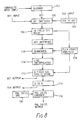
- A particularly preferred form of the present invention will now be described with reference to the diagram which is Figure 8.
- The illustrated NTSC to PAL standards converter operates with the recognised 601 digital format but can accept video signals in NTSC, YUV or 601 formats. Thus, a 601
switcher 100 is connected to receive inputs from anNTSC decoder 102 and aYUV decoder 104 as well as to receive 60 signals direct. The output of the 601switcher 100 is passed to a 16field delay 106. A filmframe analysis unit 108 receives comparison information from the delay, in the manner described previously. Outputs from theanalysis unit 108 are taken to thesequencer 110 andcyclic field store 112. Thesequencer 110 functions as has been described above to identify the 3/2 sequence. This information is available continuously and, because of thedelay 106, in real time with the passage of the video signal. Any cuts are identifed and fresh sequence information applied immediately after any cut. The output of thesequencer 110 passes to aline interpolator 114 connected in turn with thecyclic field store 112. Together, the line interpolator and cyclic field store construct digital output fields in the PAL standard. The manner in which this is achieved is preferably as described generally in published copending international patent application no. W090/03705 to which reference is directed. The line interpolation differs from that described in the co-pending application in that, normally, two interlaced fields of anoutput 625 video frame are constructed by line interpolation of a 525 video frame known (as a result of the actions of the filmframe analysis unit 108 and sequencer 110) to derive from a single film frame. In the event of the filmframe analysis unit 108 detecting a cut in the input video signal, line interpolation is switched momentarily to a cut mode in which two interlaced fields of a 625 video frame are constructed from a single field of the 525 signal. As has been described above, this avoids the risk of visually disturbing artefacts arising from an attempt to line interpolate from conceptually disparate images. - The output of the
cyclic field store 112 is available directly as a 601 output and is also passed to digital-to-analogue converter 116. The output ofconverter 116 is made available directly as a YUV output and also passes toPAL encoder 118. As mentioned earlier, the apparatus can produce aPAL output 24 or 25 frames per second and appropriate timing signals are taken fromsync pulse generator 120. - It should be understood that this invention has been described by way of examples only and a variety of further modifications are possible without departing from the scope of the invention. Thus, for example, whilst the use of eight video field delay units is believed to be preferable, a lesser multi-field delay may offer some advantages. Increasing the multi-field delay to more than eight fields would improve the accuracy with which the motion analysis unit can identify the 3/2 sequence although a much increased number of field delays might prove economically impracticable.
Claims (13)
- A television standards conversion process for use with a 30 frame per second input video signal generated from 24 frames per second film material with a repeating field duplication and reordering sequence which may be disrupted due to the presence of, for example, edits in the input video signal, wherein phase information concerning the phase in the input video signal of said repeating sequence is utilised to construct video frames in an output video signal characterised by the steps of comparing fields from successive video frames to identify duplicated fields and deriving from said identification of duplicated fields continuous phase information concerning the phase in the input video signal of said repeating sequence.
- A process according to Claim 1, wherein the step of constructing video frames comprises the step of constructing 24 video frames per second corresponding one for one with frames of the original film material.
- A process according to Claim 2, wherein a pair of interlaced output video fields are derived at a line standard different from that of the input video signal through line interpolation from each one of said 24 video frames.
- A process according to any one of Claims 1, 2 and 3, wherein the step of constructing video frames comprises the step of constructing 24 video frames per second.
- A process according to any one of the preceding claims, further comprising the step of storing at least four and preferably at least eight successive fields of the input video signal to provide a multi field delay between the said steps of comparing fields from successive video frames and constructing video frames in an output video signal.
- A process according to Claim 1, comprising the further step of conducting line interpolation on said video frames to provide video fields at a line standard different from that of the input video signal.
- A process according to Claim 6, wherein the step of comparing fields also functions to detect pairs of fields having a high degree of difference indicative of a film or video cut and wherein line interpolation is conducted on said video frames in a cut mode on detection of such a cut and otherwise in a normal mode, the cut mode comprising the generation of two output video fields from one field of said video frame, the normal mode comprising the generation of two output video fields each utilising information from both fields of the video frame.
- A process according to Claim 1, wherein the 24 video frame per second output signal is recorded on tape so as to provide through modification of tape speed for viewing on 25 frame per second equipment.
- A digital television standards converter for use with film-originating video signals having a repeating field duplication and re-ordering sequence which may be disrupted due to the presence of, for example, edits in the input video signal, comprising converter means for generating a video output utilising phase information concerning the phase in the input video of said repeating sequence, characterised by means for comparing fields in successive frames and means for detecting through said comparison duplicate fields deriving from the same film field in order to derive continuous phase information concerning the phase in the input video signal of said repeating sequence.
- A converter according to Claim 9, further comprising a multi-field delay line downstream of said means for comparing fields in successive frames; sequencer means for analysis of successive outputs of said means for comparing fields and providing said phase information.
- A converter according to Claim 9 or Claim 10, wherein said converter means comprises line interpolator means functioning to derive two output video fields at a line standard different from that of the film originating video signal through line interpolation of a video frame in said film originating video signal corresponding with a film frame.
- A converter according to any one of Claims 10 to 12, wherein said sequencer means further comprises cut detector means for detecting cuts in the film originating video signal through a high degree of difference in said compared fields and wherein said converter means is adapted to apply fresh phase information resulting from any such cut at a point in the video signal immediately after said cut.
- A converter according to Claim 12, wherein said converter means comprises line interpolator means operating in a normal mode to derive two output video fields from a video frame in the film originating video signal corresponding with a single film frame and operating in a cut mode to derive two output video fields from a video field in the film originating video signal, said converter means being arranged to switch to said cut mode of operation on detection of said high degree of difference.
Applications Claiming Priority (5)
| Application Number | Priority Date | Filing Date | Title |
|---|---|---|---|
| GB8923649 | 1989-10-20 | ||
| GB898923649A GB8923649D0 (en) | 1989-10-20 | 1989-10-20 | Digital television standards conversion |
| GB909007214A GB9007214D0 (en) | 1990-03-30 | 1990-03-30 | Digital television standards conversion |
| GB9007214 | 1990-03-30 | ||
| PCT/GB1990/001619 WO1991006182A1 (en) | 1989-10-20 | 1990-10-22 | Digital television standards conversion |
Publications (2)
| Publication Number | Publication Date |
|---|---|
| EP0461209A1 EP0461209A1 (en) | 1991-12-18 |
| EP0461209B1 true EP0461209B1 (en) | 1996-10-09 |
Family
ID=26296081
Family Applications (1)
| Application Number | Title | Priority Date | Filing Date |
|---|---|---|---|
| EP90915784A Expired - Lifetime EP0461209B1 (en) | 1989-10-20 | 1990-10-22 | Digital television standards conversion |
Country Status (12)
| Country | Link |
|---|---|
| US (1) | US5255091A (en) |
| EP (1) | EP0461209B1 (en) |
| JP (1) | JPH04502545A (en) |
| AT (1) | ATE144092T1 (en) |
| AU (1) | AU648759B2 (en) |
| CA (1) | CA2044255A1 (en) |
| DE (1) | DE69028847T2 (en) |
| DK (1) | DK0461209T3 (en) |
| ES (1) | ES2095259T3 (en) |
| GR (1) | GR3022234T3 (en) |
| HK (1) | HK1002247A1 (en) |
| WO (1) | WO1991006182A1 (en) |
Families Citing this family (44)
| Publication number | Priority date | Publication date | Assignee | Title |
|---|---|---|---|---|
| US4998167A (en) * | 1989-11-14 | 1991-03-05 | Jaqua Douglas A | High resolution translation of images |
| US5408265A (en) * | 1992-02-07 | 1995-04-18 | Olympus Optical Co., Ltd. | Electronic endoscope system adaptable to different T.V. standards while utilizing a common light source |
| GB2265782B (en) * | 1992-03-30 | 1996-01-10 | Snell & Wilcox Ltd | Digital television standards conversion |
| US5715018A (en) * | 1992-04-10 | 1998-02-03 | Avid Technology, Inc. | Digital advertisement insertion system |
| US5418572A (en) * | 1992-04-29 | 1995-05-23 | Quantel Limited | Method of and apparatus for displaying images at different rates |
| JP2618587B2 (en) * | 1992-06-02 | 1997-06-11 | プロデューサーズ カラー サーヴィス、インコーポレイテッド | An image frame identification system that can be effectively applied to the frame still mode |
| CA2139420C (en) * | 1992-07-01 | 2000-12-12 | Eric C. Peters | Electronic film editing system using both film and videotape format |
| US5461420A (en) * | 1992-09-18 | 1995-10-24 | Sony Corporation | Apparatus for coding and decoding a digital video signal derived from a motion picture film source |
| JP3443880B2 (en) * | 1992-09-18 | 2003-09-08 | ソニー株式会社 | Video signal encoding method and decoding method |
| GB2272816B (en) * | 1992-11-17 | 1996-07-24 | Sony Broadcast & Communication | Video signal processing |
| US5491516A (en) * | 1993-01-14 | 1996-02-13 | Rca Thomson Licensing Corporation | Field elimination apparatus for a video compression/decompression system |
| FR2702914B1 (en) * | 1993-03-17 | 1995-06-16 | Philips Laboratoire Electroniq | DEVICE FOR CODING SUITES OF IMAGES CONSISTING OF FILM-TYPE IMAGES AND VIDEO-TYPE IMAGES, AND CORRESPONDING DECODING DEVICE. |
| US5598514A (en) * | 1993-08-09 | 1997-01-28 | C-Cube Microsystems | Structure and method for a multistandard video encoder/decoder |
| US5828786A (en) * | 1993-12-02 | 1998-10-27 | General Instrument Corporation | Analyzer and methods for detecting and processing video data types in a video data stream |
| GB9401897D0 (en) * | 1994-02-01 | 1994-03-30 | Snell & Wilcox Ltd | Video processing |
| GB9404190D0 (en) | 1994-03-04 | 1994-04-20 | Snell & Wilcox Limited Video | Video signal processing |
| US5452011A (en) * | 1994-03-14 | 1995-09-19 | Thomson Consumer Electronics, Inc. | Method and device for film-mode detection and field elimination |
| JP2947400B2 (en) * | 1994-05-31 | 1999-09-13 | 日本ビクター株式会社 | Frame frequency converter |
| US5596371A (en) * | 1995-02-02 | 1997-01-21 | Dwin Electronics Inc. | Film-mode video line-doubler motion detectors |
| US5671008A (en) * | 1995-02-23 | 1997-09-23 | Maestroworks Inc | Telecine system |
| JP3094903B2 (en) * | 1995-06-08 | 2000-10-03 | 松下電器産業株式会社 | Television signal conversion device and image coding device |
| US5910909A (en) * | 1995-08-28 | 1999-06-08 | C-Cube Microsystems, Inc. | Non-linear digital filters for interlaced video signals and method thereof |
| US6058140A (en) * | 1995-09-08 | 2000-05-02 | Zapex Technologies, Inc. | Method and apparatus for inverse 3:2 pulldown detection using motion estimation information |
| US5757435A (en) * | 1995-12-08 | 1998-05-26 | C-Cube Microsystems, Inc. | MPEG-2 inverse telecine circuit |
| JP2906332B2 (en) * | 1995-12-27 | 1999-06-21 | 日本テレビ放送網株式会社 | Telecine signal conversion method and up-converter |
| US5734443A (en) * | 1995-12-28 | 1998-03-31 | Philips Electronics North America Corporation | Method and device for performing source transitions in a video system which performs entropy encoding |
| KR100223205B1 (en) * | 1996-08-05 | 1999-10-15 | 윤종용 | Method for playing video signal in digital video disk |
| US6222589B1 (en) | 1996-08-08 | 2001-04-24 | Yves C. Faroudja | Displaying video on high-resolution computer-type monitors substantially without motion discontinuities |
| JP3523026B2 (en) * | 1997-09-04 | 2004-04-26 | 三菱電機株式会社 | Image signal processing device |
| US6014182A (en) * | 1997-10-10 | 2000-01-11 | Faroudja Laboratories, Inc. | Film source video detection |
| US6108041A (en) * | 1997-10-10 | 2000-08-22 | Faroudja Laboratories, Inc. | High-definition television signal processing for transmitting and receiving a television signal in a manner compatible with the present system |
| US6111610A (en) * | 1997-12-11 | 2000-08-29 | Faroudja Laboratories, Inc. | Displaying film-originated video on high frame rate monitors without motions discontinuities |
| US6297848B1 (en) | 1998-11-25 | 2001-10-02 | Sharp Laboratories Of America, Inc. | Low-delay conversion of 3:2 pulldown video to progressive format with field averaging |
| US6408024B1 (en) * | 1999-05-12 | 2002-06-18 | Matsushita Electric Industrial Co., Ltd. | Telecine video signal detecting device |
| US6377297B1 (en) * | 1999-12-07 | 2002-04-23 | Tektronix, Inc. | Detection of repeated and frozen frames in a video signal |
| JP2001333391A (en) * | 2000-05-18 | 2001-11-30 | Nec Corp | Video display device |
| US6859235B2 (en) * | 2001-05-14 | 2005-02-22 | Webtv Networks Inc. | Adaptively deinterlacing video on a per pixel basis |
| EP1720166A1 (en) * | 2005-05-04 | 2006-11-08 | Deutsche Thomson-Brandt Gmbh | Method and apparatus for authoring a 24p audio/video data stream by supplementing it with additional 50i format data items |
| JP2006339857A (en) * | 2005-05-31 | 2006-12-14 | Toshiba Corp | Decoding device |
| FR2901951A1 (en) | 2006-06-06 | 2007-12-07 | St Microelectronics Sa | Digital video image frequency detecting method for e.g. digital set top box, involves dividing current frame into region based on determined phase value by statistics and segmentation unit and assigning region movement phase value to region |
| FR2902265A1 (en) | 2006-06-13 | 2007-12-14 | St Microelectronics Sa | Video frame frequency detecting method for e.g. TV set, involves updating bits for each frame using two binary signals respectively indicating frames suppression orders and frames repetition orders which are previously applied to frames |
| CN101448080B (en) * | 2007-11-27 | 2012-03-28 | 鸿富锦精密工业(深圳)有限公司 | Imaging device and image display method |
| JP4643727B2 (en) * | 2009-05-29 | 2011-03-02 | 株式会社東芝 | Image processing apparatus and image processing method |
| TWI629647B (en) * | 2017-11-22 | 2018-07-11 | 英業達股份有限公司 | Viedo-recording and target-counting device |
Family Cites Families (13)
| Publication number | Priority date | Publication date | Assignee | Title |
|---|---|---|---|---|
| GB1191500A (en) * | 1967-10-10 | 1970-05-13 | British Broadcasting Corp | Television Standards Conversions. |
| US4399465A (en) * | 1980-10-17 | 1983-08-16 | Robert Bosch Gmbh | System for scanning of motion picture films to derive television signals |
| GB2129651B (en) * | 1982-10-28 | 1986-08-06 | Quantel Ltd | Video processors |
| JPS60204182A (en) * | 1984-03-28 | 1985-10-15 | Sony Corp | Editing system of video signal |
| DE3520333A1 (en) * | 1985-06-07 | 1986-12-11 | Robert Bosch Gmbh, 7000 Stuttgart | METHOD FOR THE IMAGE-EXACT TRANSFER OF FILM SCENES TO MAGNETIC TAPE AND CIRCUIT ARRANGEMENT THEREFOR |
| US4779131A (en) * | 1985-07-26 | 1988-10-18 | Sony Corporation | Apparatus for detecting television image movement |
| GB8822415D0 (en) * | 1988-09-23 | 1988-10-26 | Snell & Wilcox Electronic Cons | Video signal processing & video stores |
| US4876596A (en) * | 1988-10-25 | 1989-10-24 | Faroudja Y C | Film-to-video converter with scan line doubling |
| US4982280A (en) * | 1989-07-18 | 1991-01-01 | Yves C. Faroudja | Motion sequence pattern detector for video |
| US4998167A (en) * | 1989-11-14 | 1991-03-05 | Jaqua Douglas A | High resolution translation of images |
| US5115311A (en) * | 1989-11-14 | 1992-05-19 | Shell Oil Company | High resolution translation of images |
| JP2773337B2 (en) * | 1989-12-29 | 1998-07-09 | ソニー株式会社 | Video signal conversion method |
| GB9001079D0 (en) * | 1990-01-17 | 1990-03-14 | Avesco Plc | Standards conversion |
-
1990
- 1990-10-22 EP EP90915784A patent/EP0461209B1/en not_active Expired - Lifetime
- 1990-10-22 ES ES90915784T patent/ES2095259T3/en not_active Expired - Lifetime
- 1990-10-22 DE DE69028847T patent/DE69028847T2/en not_active Expired - Lifetime
- 1990-10-22 US US07/720,512 patent/US5255091A/en not_active Expired - Lifetime
- 1990-10-22 AT AT90915784T patent/ATE144092T1/en active
- 1990-10-22 WO PCT/GB1990/001619 patent/WO1991006182A1/en active IP Right Grant
- 1990-10-22 CA CA002044255A patent/CA2044255A1/en not_active Abandoned
- 1990-10-22 AU AU66138/90A patent/AU648759B2/en not_active Ceased
- 1990-10-22 JP JP2514821A patent/JPH04502545A/en active Pending
- 1990-10-22 DK DK90915784.4T patent/DK0461209T3/da active
-
1997
- 1997-01-09 GR GR960403366T patent/GR3022234T3/en unknown
-
1998
- 1998-02-19 HK HK98101282A patent/HK1002247A1/en not_active IP Right Cessation
Also Published As
| Publication number | Publication date |
|---|---|
| DE69028847T2 (en) | 1997-04-03 |
| JPH04502545A (en) | 1992-05-07 |
| AU6613890A (en) | 1991-05-16 |
| EP0461209A1 (en) | 1991-12-18 |
| CA2044255A1 (en) | 1991-04-21 |
| ATE144092T1 (en) | 1996-10-15 |
| AU648759B2 (en) | 1994-05-05 |
| DK0461209T3 (en) | 1997-02-17 |
| WO1991006182A1 (en) | 1991-05-02 |
| ES2095259T3 (en) | 1997-02-16 |
| HK1002247A1 (en) | 1998-08-07 |
| DE69028847D1 (en) | 1996-11-14 |
| US5255091A (en) | 1993-10-19 |
| GR3022234T3 (en) | 1997-04-30 |
Similar Documents
| Publication | Publication Date | Title |
|---|---|---|
| EP0461209B1 (en) | Digital television standards conversion | |
| US5485280A (en) | Apparatus and method for producing downwards compatible video signals with increased vertical resolution, and apparatus for reproducing and displaying same | |
| US5517248A (en) | Frame-frequency converting apparatus for a video signal resulting from 2-3 conversion of original picture information | |
| JP4306810B2 (en) | Film source video detection | |
| US20070064148A1 (en) | Methods and apparatus for correction of 2-3 field patterns | |
| US5221966A (en) | Video signal production from cinefilm originated material | |
| US6480232B1 (en) | Video processing to convert between field rates | |
| KR0145161B1 (en) | Video signal recording apparatus and reproducing apparatus | |
| EP0404383A2 (en) | Apparatus for recording and reproducing video signals of high resolution image | |
| GB2240232A (en) | Converting field rate of telecine signal | |
| JP3149331B2 (en) | Digital image data processing device | |
| US5450506A (en) | Image data processing apparatus and method | |
| EP1127455B1 (en) | Video signal processing | |
| JPH06101855B2 (en) | Video signal converter | |
| GB2265782A (en) | Films originating video signal standards conversion | |
| CA2073736C (en) | Apparatus and method for recording digital video signals | |
| US6256450B1 (en) | Progressive scanned signal processing apparatus | |
| JPH10210498A (en) | Edit device for image data | |
| JPH02262791A (en) | Digital video signal recorder | |
| JPH05145949A (en) | Drop-out compensator |
Legal Events
| Date | Code | Title | Description |
|---|---|---|---|
| PUAI | Public reference made under article 153(3) epc to a published international application that has entered the european phase |
Free format text: ORIGINAL CODE: 0009012 |
|
| 17P | Request for examination filed |
Effective date: 19911001 |
|
| AK | Designated contracting states |
Kind code of ref document: A1 Designated state(s): AT BE CH DE DK ES FR GB GR IT LI LU NL SE |
|
| 17Q | First examination report despatched |
Effective date: 19930820 |
|
| GRAG | Despatch of communication of intention to grant |
Free format text: ORIGINAL CODE: EPIDOS AGRA |
|
| GRAH | Despatch of communication of intention to grant a patent |
Free format text: ORIGINAL CODE: EPIDOS IGRA |
|
| GRAH | Despatch of communication of intention to grant a patent |
Free format text: ORIGINAL CODE: EPIDOS IGRA |
|
| GRAA | (expected) grant |
Free format text: ORIGINAL CODE: 0009210 |
|
| AK | Designated contracting states |
Kind code of ref document: B1 Designated state(s): AT BE CH DE DK ES FR GB GR IT LI LU NL SE |
|
| REF | Corresponds to: |
Ref document number: 144092 Country of ref document: AT Date of ref document: 19961015 Kind code of ref document: T |
|
| RAP2 | Party data changed (patent owner data changed or rights of a patent transferred) |
Owner name: SNELL & WILCOX LIMITED |
|
| REF | Corresponds to: |
Ref document number: 69028847 Country of ref document: DE Date of ref document: 19961114 |
|
| ET | Fr: translation filed | ||
| ITF | It: translation for a ep patent filed |
Owner name: ING. A. GIAMBROCONO & C. S.R.L. |
|
| NLT2 | Nl: modifications (of names), taken from the european patent patent bulletin |
Owner name: SNELL & WILCOX LIMITED |
|
| REG | Reference to a national code |
Ref country code: CH Ref legal event code: NV Representative=s name: ISLER & PEDRAZZINI AG |
|
| REG | Reference to a national code |
Ref country code: ES Ref legal event code: FG2A Ref document number: 2095259 Country of ref document: ES Kind code of ref document: T3 |
|
| REG | Reference to a national code |
Ref country code: DK Ref legal event code: T3 |
|
| REG | Reference to a national code |
Ref country code: GR Ref legal event code: FG4A Free format text: 3022234 |
|
| PLBE | No opposition filed within time limit |
Free format text: ORIGINAL CODE: 0009261 |
|
| STAA | Information on the status of an ep patent application or granted ep patent |
Free format text: STATUS: NO OPPOSITION FILED WITHIN TIME LIMIT |
|
| 26N | No opposition filed | ||
| PGFP | Annual fee paid to national office [announced via postgrant information from national office to epo] |
Ref country code: ES Payment date: 20001005 Year of fee payment: 11 |
|
| PGFP | Annual fee paid to national office [announced via postgrant information from national office to epo] |
Ref country code: SE Payment date: 20001006 Year of fee payment: 11 Ref country code: LU Payment date: 20001006 Year of fee payment: 11 |
|
| PGFP | Annual fee paid to national office [announced via postgrant information from national office to epo] |
Ref country code: DK Payment date: 20001009 Year of fee payment: 11 |
|
| PGFP | Annual fee paid to national office [announced via postgrant information from national office to epo] |
Ref country code: GR Payment date: 20001010 Year of fee payment: 11 |
|
| PGFP | Annual fee paid to national office [announced via postgrant information from national office to epo] |
Ref country code: AT Payment date: 20001020 Year of fee payment: 11 |
|
| PGFP | Annual fee paid to national office [announced via postgrant information from national office to epo] |
Ref country code: NL Payment date: 20001031 Year of fee payment: 11 |
|
| PGFP | Annual fee paid to national office [announced via postgrant information from national office to epo] |
Ref country code: CH Payment date: 20001101 Year of fee payment: 11 |
|
| PGFP | Annual fee paid to national office [announced via postgrant information from national office to epo] |
Ref country code: BE Payment date: 20001103 Year of fee payment: 11 |
|
| PG25 | Lapsed in a contracting state [announced via postgrant information from national office to epo] |
Ref country code: DK Free format text: LAPSE BECAUSE OF NON-PAYMENT OF DUE FEES Effective date: 20011022 Ref country code: LU Free format text: LAPSE BECAUSE OF NON-PAYMENT OF DUE FEES Effective date: 20011022 Ref country code: AT Free format text: LAPSE BECAUSE OF NON-PAYMENT OF DUE FEES Effective date: 20011022 |
|
| PG25 | Lapsed in a contracting state [announced via postgrant information from national office to epo] |
Ref country code: SE Free format text: LAPSE BECAUSE OF NON-PAYMENT OF DUE FEES Effective date: 20011023 Ref country code: ES Free format text: LAPSE BECAUSE OF NON-PAYMENT OF DUE FEES Effective date: 20011023 |
|
| PG25 | Lapsed in a contracting state [announced via postgrant information from national office to epo] |
Ref country code: GR Free format text: LAPSE BECAUSE OF NON-PAYMENT OF DUE FEES Effective date: 20011031 Ref country code: LI Free format text: LAPSE BECAUSE OF NON-PAYMENT OF DUE FEES Effective date: 20011031 Ref country code: CH Free format text: LAPSE BECAUSE OF NON-PAYMENT OF DUE FEES Effective date: 20011031 Ref country code: BE Free format text: LAPSE BECAUSE OF NON-PAYMENT OF DUE FEES Effective date: 20011031 |
|
| REG | Reference to a national code |
Ref country code: GB Ref legal event code: IF02 |
|
| BERE | Be: lapsed |
Owner name: SNELL & WILCOX LTD Effective date: 20011031 |
|
| PG25 | Lapsed in a contracting state [announced via postgrant information from national office to epo] |
Ref country code: NL Free format text: LAPSE BECAUSE OF NON-PAYMENT OF DUE FEES Effective date: 20020501 |
|
| EUG | Se: european patent has lapsed |
Ref document number: 90915784.4 |
|
| REG | Reference to a national code |
Ref country code: CH Ref legal event code: PL |
|
| REG | Reference to a national code |
Ref country code: DK Ref legal event code: EBP |
|
| NLV4 | Nl: lapsed or anulled due to non-payment of the annual fee |
Effective date: 20020501 |
|
| REG | Reference to a national code |
Ref country code: ES Ref legal event code: FD2A Effective date: 20021113 |
|
| PG25 | Lapsed in a contracting state [announced via postgrant information from national office to epo] |
Ref country code: IT Free format text: LAPSE BECAUSE OF NON-PAYMENT OF DUE FEES;WARNING: LAPSES OF ITALIAN PATENTS WITH EFFECTIVE DATE BEFORE 2007 MAY HAVE OCCURRED AT ANY TIME BEFORE 2007. THE CORRECT EFFECTIVE DATE MAY BE DIFFERENT FROM THE ONE RECORDED. Effective date: 20051022 |
|
| REG | Reference to a national code |
Ref country code: GB Ref legal event code: 732E Free format text: REGISTERED BETWEEN 20090924 AND 20090930 |
|
| PGFP | Annual fee paid to national office [announced via postgrant information from national office to epo] |
Ref country code: GB Payment date: 20090914 Year of fee payment: 20 |
|
| PGFP | Annual fee paid to national office [announced via postgrant information from national office to epo] |
Ref country code: DE Payment date: 20091030 Year of fee payment: 20 |
|
| PGFP | Annual fee paid to national office [announced via postgrant information from national office to epo] |
Ref country code: FR Payment date: 20091020 Year of fee payment: 20 |
|
| REG | Reference to a national code |
Ref country code: GB Ref legal event code: PE20 Expiry date: 20101021 |
|
| PG25 | Lapsed in a contracting state [announced via postgrant information from national office to epo] |
Ref country code: GB Free format text: LAPSE BECAUSE OF EXPIRATION OF PROTECTION Effective date: 20101021 |
|
| PG25 | Lapsed in a contracting state [announced via postgrant information from national office to epo] |
Ref country code: DE Free format text: LAPSE BECAUSE OF EXPIRATION OF PROTECTION Effective date: 20101022 |