EP0460477A1 - Monocrystal rod conveying apparatus - Google Patents
Monocrystal rod conveying apparatus Download PDFInfo
- Publication number
- EP0460477A1 EP0460477A1 EP91108514A EP91108514A EP0460477A1 EP 0460477 A1 EP0460477 A1 EP 0460477A1 EP 91108514 A EP91108514 A EP 91108514A EP 91108514 A EP91108514 A EP 91108514A EP 0460477 A1 EP0460477 A1 EP 0460477A1
- Authority
- EP
- European Patent Office
- Prior art keywords
- monocrystal
- monocrystal rod
- conveying apparatus
- shaft
- base
- Prior art date
- Legal status (The legal status is an assumption and is not a legal conclusion. Google has not performed a legal analysis and makes no representation as to the accuracy of the status listed.)
- Granted
Links
Images




Classifications
-
- C—CHEMISTRY; METALLURGY
- C30—CRYSTAL GROWTH
- C30B—SINGLE-CRYSTAL GROWTH; UNIDIRECTIONAL SOLIDIFICATION OF EUTECTIC MATERIAL OR UNIDIRECTIONAL DEMIXING OF EUTECTOID MATERIAL; REFINING BY ZONE-MELTING OF MATERIAL; PRODUCTION OF A HOMOGENEOUS POLYCRYSTALLINE MATERIAL WITH DEFINED STRUCTURE; SINGLE CRYSTALS OR HOMOGENEOUS POLYCRYSTALLINE MATERIAL WITH DEFINED STRUCTURE; AFTER-TREATMENT OF SINGLE CRYSTALS OR A HOMOGENEOUS POLYCRYSTALLINE MATERIAL WITH DEFINED STRUCTURE; APPARATUS THEREFOR
- C30B15/00—Single-crystal growth by pulling from a melt, e.g. Czochralski method
- C30B15/30—Mechanisms for rotating or moving either the melt or the crystal
-
- C—CHEMISTRY; METALLURGY
- C30—CRYSTAL GROWTH
- C30B—SINGLE-CRYSTAL GROWTH; UNIDIRECTIONAL SOLIDIFICATION OF EUTECTIC MATERIAL OR UNIDIRECTIONAL DEMIXING OF EUTECTOID MATERIAL; REFINING BY ZONE-MELTING OF MATERIAL; PRODUCTION OF A HOMOGENEOUS POLYCRYSTALLINE MATERIAL WITH DEFINED STRUCTURE; SINGLE CRYSTALS OR HOMOGENEOUS POLYCRYSTALLINE MATERIAL WITH DEFINED STRUCTURE; AFTER-TREATMENT OF SINGLE CRYSTALS OR A HOMOGENEOUS POLYCRYSTALLINE MATERIAL WITH DEFINED STRUCTURE; APPARATUS THEREFOR
- C30B15/00—Single-crystal growth by pulling from a melt, e.g. Czochralski method
-
- Y—GENERAL TAGGING OF NEW TECHNOLOGICAL DEVELOPMENTS; GENERAL TAGGING OF CROSS-SECTIONAL TECHNOLOGIES SPANNING OVER SEVERAL SECTIONS OF THE IPC; TECHNICAL SUBJECTS COVERED BY FORMER USPC CROSS-REFERENCE ART COLLECTIONS [XRACs] AND DIGESTS
- Y10—TECHNICAL SUBJECTS COVERED BY FORMER USPC
- Y10T—TECHNICAL SUBJECTS COVERED BY FORMER US CLASSIFICATION
- Y10T117/00—Single-crystal, oriented-crystal, and epitaxy growth processes; non-coating apparatus therefor
- Y10T117/10—Apparatus
- Y10T117/1024—Apparatus for crystallization from liquid or supercritical state
- Y10T117/1032—Seed pulling
- Y10T117/1072—Seed pulling including details of means providing product movement [e.g., shaft guides, servo means]
Definitions
- the present invention relates to a monocrystal rod conveying apparatus for taking out a grown monocrystal rod from a monocrystal growing device and conveying it to a predetermined position.
- a monocrystal pulling up device acting in accordance with the CZ method is arranged in such a manner that a monocrystal is grown in a main chamber under vacuum.
- the monocrystal rod is raised into a pull chamber disposed above the main chamber before a gate disposed at the junction between the main chamber and the pull chamber is closed while opening a shutting door disposed in the pull chamber. Then, the monocrystal rod is taken out.
- a conveying device must be provided to each monocrystal pulling up device for the purpose of conveying the monocrystal rod which has been unloaded from the pull chamber.
- an object of the present invention is to provide a monocrystal rod conveying apparatus capable of simplifying the overall structure, which takes care of a plurality of monocrystal pulling devices, and reducing the overall cost.
- a monocrystal rod conveying apparatus for unloading monocrystal rods grown in a plurality of monocrystal pulling devices disposed in series and conveying them, the monocrystal rod conveying apparatus comprising: guide means disposed along a plurality of the monocrystal pulling devices; a traveling portion for travelling along the guide means; a body portion, an end portion of which, is secured to the travelling portion; a hand portion for holding/releasing the monocrystal rod; a movable base portion for supporting the hand portion; and an expansion portion arranged in such a manner that its end portion is fastened to the body portion and another end portion is fastened to the movable base portion, the expansion portion being capable of changing the distance between the body portion and the movable base.
- the expansion portion is expanded so that the hand portion is introduced into the pull chamber of the monocrystal pulling up device. Then, the hand portion is closed so that the monocrystal rod is held before the expansion portion is contracted. Then, the monocrystal rod is conveyed by means of the travelling portion along the guide means to a predetermined position.
- the monocrystal rod conveying apparatus is independently structured from the monocrystal pulling device.
- the necessity of providing a conveying device to each monocrystal pulling up device to convey the monocrystal rod unloaded from the monocrystal pulling device to a predetermined position can be eliminated. Therefore, the overall structure can be simplified and the overall cost can be reduced.
- the above-described body portion includes: a base portion secured to the travelling portion; and a rotational portion capable of rotating around a vertical shaft with respect to the position of the base portion, the end portion of the expansion portion being fastened to the rotational portion.
- the expansion portion and the hand portion are caused to face the traveling direction.
- the monocrystal rod is unloaded from the monocrystal pulling device, the expansion portion and the hand portion are rotated toward the monocrystal pulling device.
- the width in a direction perpendicular to the travelling direction can be reduced at the time of travelling. Therefore, a sufficiently wide passage can be created and the safety of the operators can be improved.
- the above-described movable base includes: a back base secured to the other end portion of the expansion portion; and a tilt base to which the hand portion is fastened, the tilt base being fastened in such a manner that it is capable of rotating around a horizontal shaft in the lower portion with respect to the position of the back base, the hand portion being provided for the tilt base.
- the monocrystal rod is conveyed to a predetermined position before the tilt base is made to be horizontal and the hand portion is opened.
- the monocrystal rod is placed on, for example, a conveyer disposed adjacently.
- the above-described guide means is a rail disposed adjacently to the ceiling of a factory.
- the space below the rail can be reduced.
- the above-described body portion is arranged in such a manner that the rotational portion is able to move vertically with respect to the position of the base portion.
- the space below the rail can be effectively utilized and the safety of the operators can be satisfactorily improved.
- Figs. 1 to 6H illustrate an embodiment of a monocrystal rod conveying apparatus according to the present invention, where
- a row of monocrystal pulling up devices 10 to 14 there are a row of monocrystal pulling up devices 10 to 14 disposed at predetermined intervals in a factory.
- Each of the monocrystal pulling up devices 10 to 14 is arranged in such a manner that a pull-chamber 21 is concentrically formed with an opening formed in the upper portion of a main chamber 20 which includes a quarts crusible or the like.
- a grown monocrystal rod 22 is accommodated in the pull chamber 21 while being suspended from a pulling wire.
- the pull chamber 21 has a shutting door 24 having a window 23 formed therein.
- a conveyer 30 is arranged in a direction perpendicular to the direction of the row of the monocrystal pulling up devices 10 to 14, the conveyer 30 being disposed by the side of the monocrystal pulling up device 14.
- a rail 31 is disposed adjacent to the ceiling of the factory, the rail 31 extending along the row of the monocrystal pulling up devices 10 to 14 from a portion diagonally above the monocrystal pulling up device 10 to a portion above the conveyer 30.
- a travelling portion 33 of a monocrystal rod conveying device 32 is fastened to the rail 31 in such a manner that the travelling portion 33 is able to move along the rail 31.
- an upper cylinder 36 is, via a neck portion 35, secured to the bottom surface of the travelling portion 33.
- a bearing 36A is fixed to the inner surface of the upper cylinder 36 which is vertically placed.
- the bearing 36A has a key 36a projecting inwardly and formed in the axial direction of the bearing 36A.
- a key seat extending in the axial direction of an elevational shaft 37 is formed in the surface of the elevational shaft 37, the key seat being formed to correspond to the above-described key 36a.
- the elevational shaft 37 is inserted into the bearing 36A in a state where the key 36a is fitted within the above-described key seat.
- a geared motor 38 having the output shaft, to which a take-up drum is fastened, is secured to the inside portion of the neck portion 35.
- a pulley 38a is journalled in the neck portion 35 and a wire 36b is arranged in such a manner that it is wound around the take-up drum and the terminative end of the wire 38b is secured to the central portion of the upper end surface of the elevational shaft 37 via the pulley 38a.
- a lower cylinder 39 having bearings 39a at the two end portions thereof is fastened around the lower portion of the elevational shaft 37 in such a manner that the lower cylinder 39 can be rotated with respect to the position of the elevational shaft 37 and its vertical movement is prohibited.
- a geared motor 40 is fastened to the lower cylinder 39 in such a manner that a gear 40a secured to the output shaft of the geared motor 40 is engaged with a gear 40b secured to the bottom end of the elevational shaft 37.
- An end portion of an arm cylinder 41 is secured to the outer surface of the lower cylinder 39 in a direction perpendicular to the lower cylinder 39.
- An arm shaft 42 perpendicularly secured to a back base plate 44 at an end portion thereof is inserted into the arm cylinder 41.
- a motor cylinder 43 is disposed between the above-described two elements. As a result, when the motor cylinder 43 is expanded/contracted, the arm shaft 42 is moved in the axial direction of the arm cylinder 41.
- a tilt base plate 45 is disposed in front of the back base plate 44, the tilt base plate 45 being placed in parallel with the back base plate 44.
- the tilt base plate 45 is journalled by a support shaft 46 which is horizontally placed in the lower portion of the back base plate 44.
- An end portion of a wire 47 is connected to the top end portion of the tilt base plate 45, the wire 47 being wound around a drum 49 after it has been wound to the pulley 48.
- the drum 49 is rotated by a geared motor 50.
- the above-described pulley 48, the drum 49 and the geared motor 50 are fastened to the upper portion of the back base plate 44. Therefore, when the geared motor 50 is rotated forward/reversely, the tilt base pale 45 is rotated around the support shaft 46 in a direction in which the same is tilted/stood up.
- a finger drive portion 51A is secured to the lower portion of the front surface of the tilt base plate 45. Furthermore, a finger drive portion 51B is fastened to the tilt base plate 45 above the finger drive portion 51A in such a manner that the finger drive portion 51B is able to desirably moved in the lengthwise direction of the tilt base plate 45. As shown in Fig. 3, the finger drive portion 51B is arranged in such a manner that a feed screw 522 is, by means of a thread formed on the surface thereof, inserted into a nut 521 secured to the back side of a frame 510. As shown in Fig. 2, the feed screw 522 is journalled by the tilt base plate 45 in such a manner that the feed screw 522 is rotated by a geared motor 52.
- a channel 523 is secured to the central portion on the back side of the frame 510 in parallel with the feed screw 522, the channel 523 being engaged with a guide rail 524 secured to the tilt base plate 45. Therefore, the vertical position of the finger drive portion 51B can be adjusted in accordance with the length of the monocrystal rod 22 by the geared motor 52 fastened to the tilt base plate 45.
- a geared motor 512 is secured to the side portion of the back side of the frame 510, the geared motor 512 having an output shaft to which a spur gear 513 is secured.
- a feed screw 514 having a right-hand screw 514a on either portion thereof and a left-hand screw 514b on another portion thereof is horizontally journalled in front of the frame 510.
- a spur gear 516 which is engaged with the spur gear 513, is secured to an end of the feed screw 514 via a torque limiter 515.
- a nut 517 is received by the right-hand screw 514, while a nut 518 is received by the left-hand screw 514b.
- a guide rod (omitted from illustration) is inserted into the above-described nuts 517 and 518 in order to prevent their rotations, the guide rod being inserted in parallel with the feed screw 514.
- the base portions of holding fingers 54B and 54A are secured to the corresponding nuts 517 and 518. Therefore, when the geared motor 512 is rotated forward/reversely, the holding fingers 54A and 54B approaches each other or move away from each other. Furthermore, when the geared motor 512 is rotated forward and the monocrystal rod 22 is thereby held by the holding fingers 54A and 54B, the torque limiter 515 is caused to act so that the monocrystal rod 22 is held with predetermined force. Since the thus arranged approaching/moving away mechanism and the holding mechanism are similarly provided for the finger drive portion 51B, the descriptions about them are omitted here.
- a flange 55 is secured to the elevational shaft 37 at the uppermost position of the lower cylinder 39.
- two pins 56 are formed on the lower surface of the two end portions of the flange 55 in such a manner that the two pins 56 project downward.
- a projecting tag 25 is formed in such a manner that it projects from the support frame of each of the monocrystal pulling up devices 10 to 14, the tag 25 having holes 26 (see Fig. 1) which correspond to the above-described pins 56 (the monocrystal pulling up device 10 shown in Fig. 1 is omitted from illustration).
- a frame 15 having the same shape as the above-described support frame of each of the monocrystal pulling up devices 10 to 14 is disposed adjacently to the conveyer 30 on the extension of the row of the monocrystal pulling up devices 10 to 14.
- the projecting tag 25 is formed in such a manner that the tag 25 projects from the frame 15, the tag 25 having holes formed to correspond to the pins 56.
- command transmitting devices 60 to 64 are disposed in the side portions of the corresponding monocrystal pulling up devices 10 to 14, the command transmitting devices 60 to 64 being connected to a signal cable 66 which is arranged along the rail 31.
- a magnetic detector 67 is secured to the inner surface of the travelling portion 33 at a position adjacent to the signal line 66.
- the magnetic detector 67 is connected to a control unit 68 (see Fig. 1) fastened to the travelling portion 33.
- the above-described geared motors 34, 38, 40, 50, 511 and 52 and the motor of the motor cylinder 43 are connected to the control unit 68.
- the control unit 68 receives signals transmitted from the command transmitting devices 60 to 64 via the signal cable 66 and the magnetic detector 67 so as to control the geared motors 34, 38, 40, 43, 50 and 52 in response to the signals thus received.
- limit switches for detecting the positions, at which the operations are respectively stopped, are disposed in such a manner that they are electrically connected to the control unit 68.
- control unit 68 the control sequence of the control unit 68 will now be described with reference to Fig. 5.
- the monocrystal rod conveying apparatus 32 is positioned above the conveyer 30 to wait the operation start.
- the control unit 68 waits for an issue of each of the carry-out commands from the command transmitting devices 60 to 64.
- the geared motor 38 is turned on so that the lower cylinder 39 is moved downward to its lowermost position. As a result, a state shown in Fig. 6B is realized. At this time, the pins 56 are fitted within the holes 26 formed in the tag 25 so that the lower cylinder 39 is stabilized. (103) The geared motor 40 is turned on so as to rotate the lower cylinder 39 toward the monocrystal pulling up device 1i by an angular degree of 90°. As a result, as shown in Fig. 6C, receiving fingers 53A and 53B and the holding fingers 54A and 54B are made to confront the monocrystal rod 22. (104) The geared motor 43 is turned on so as to project the arm shaft 43 toward the arm cylinder 41 so that a state shown in Fig.
- the receiving fingers 53A and 53B and the holding fingers 54A and 54B are introduced into the pull chamber 21 so that the direction of the center line, in which the monocrystal rod 22 is held, is made coincide with the direction in which the wire, which is suspending the monocrystal rod 22, is hung.
- the operator operates the switch so as to downward move the monocrystal rod 22.
- the lower portion of the monocrystal rod 22 is introduced into and held between the receiving fingers 53A and 53B so that the monocrystal rod 22 is received.
- the holding fingers 54A and 54B are made approach each other so as to hold the monocrystal rod 22. In this state, the operation is temporarily stopped.
- the operator separates the reduced portion at the upper end portion of the monocrystal rod 22 by cutting before the operator operates the switch of the command transmitting device 6i so as to operate the monocrystal rod conveying apparatus 32.
- the control unit 68 turns on the geared motor 43 so as to return the arm shaft 43 so that a state shown in Fig. 6E is realized.
- the geared motor 40 is turned on so as to rotate the lower cylinder 39 around the elevational shaft 37 in the original direction by an angle of 90° so that a state shown in Fig. 6F is realized.
- the geared motor 38 is turned on so as to move the lower cylinder 39 to its uppermost position so that a state shown in Fig. 6G is realized.
- the geared motor 34 is turned on so as to make the monocrystal rod conveying apparatus 32 travel to a position above the conveyer 30.
- the geared motor 38 is turned on so as to move the lower cylinder 39 to its lowermost position. At this time, the pins 56 are fitted within the holes formed in the tag 25 so that the lower cylinder 39 is stabilized.
- the geared motor 40 is turned on so as to rotate the lower cylinder 39 around the elevational shaft 37 toward the forward position of the conveyer 30 by an angle of 90°.
- the geared motor 50 is turned on so as to rotate the tilt base plate 45 by an angle of 90° around the support shaft 46 in the tilting direction so that a state shown in Fig. 6H is realized.
- the distance between the receiving fingers 53A and 53B and that between the holding fingers 54A and 54B are elongated so as to release the monocrystal rod 22.
- the monocrystal rod 22 is placed on the conveyer 30.
- the geared motor 50 is turned on so as to rotate the tilt base plate 45 around the support shaft 46 by an angle of 90° in the standing direction.
- the geared motor 40 is turned on so as to rotate the lower cylinder 39 by an angle of 90° around the elevational shaft 37 toward the original position.
- the geared motor 38 is turned on so as to upward move the lower cylinder 39 to its uppermost position. Simultaneously, the distance between the receiving fingers 53A and 53B are shortened before the flow returns to step 100 in which the re-starting of the operation is waited.
- the present invention may include a variety of modifications.
- the present invention may be applied to a monocrystal pulling device arranged to act in accordance with the FZ method.
- the best mode of the structure is to dispose the rail 31 serving as the guide means adjacent to the ceiling. However, it may be disposed on the floor.
Landscapes
- Chemical & Material Sciences (AREA)
- Engineering & Computer Science (AREA)
- Crystallography & Structural Chemistry (AREA)
- Materials Engineering (AREA)
- Metallurgy (AREA)
- Organic Chemistry (AREA)
- Crystals, And After-Treatments Of Crystals (AREA)
- Manipulator (AREA)
Abstract
Description
- The present invention relates to a monocrystal rod conveying apparatus for taking out a grown monocrystal rod from a monocrystal growing device and conveying it to a predetermined position.
- For example, a monocrystal pulling up device acting in accordance with the CZ method is arranged in such a manner that a monocrystal is grown in a main chamber under vacuum. When the crystal has been grown, the monocrystal rod is raised into a pull chamber disposed above the main chamber before a gate disposed at the junction between the main chamber and the pull chamber is closed while opening a shutting door disposed in the pull chamber. Then, the monocrystal rod is taken out.
- Since the monocrystal rod thus-taken-out is heavy and hot, special devices for unloading the monocrystal rod from the pull chamber have been disclosed in Japanese Utility Model Publication No. 47-42513 and Japanese Patent Publication No. 60-41038.
- However, since the above-disclosed conventional apparatus has been integrally formed with each of monocrystal pulling up devices, the overall structure of the facility has been too complicated and the overall cost could not be reduced.
- Furthermore, since the pull chamber must be moved whenever the monocrystal rod is taken out from the pull chamber, the structure of the monocrystal pulling up device has been too complicated.
- In addition, a conveying device must be provided to each monocrystal pulling up device for the purpose of conveying the monocrystal rod which has been unloaded from the pull chamber.
- To this end, an object of the present invention is to provide a monocrystal rod conveying apparatus capable of simplifying the overall structure, which takes care of a plurality of monocrystal pulling devices, and reducing the overall cost.
- According to one aspect of the present invention, there is provided a monocrystal rod conveying apparatus for unloading monocrystal rods grown in a plurality of monocrystal pulling devices disposed in series and conveying them, the monocrystal rod conveying apparatus comprising: guide means disposed along a plurality of the monocrystal pulling devices; a traveling portion for travelling along the guide means; a body portion, an end portion of which, is secured to the travelling portion; a hand portion for holding/releasing the monocrystal rod; a movable base portion for supporting the hand portion; and an expansion portion arranged in such a manner that its end portion is fastened to the body portion and another end portion is fastened to the movable base portion, the expansion portion being capable of changing the distance between the body portion and the movable base.
- In the thus arranged structure, the expansion portion is expanded so that the hand portion is introduced into the pull chamber of the monocrystal pulling up device. Then, the hand portion is closed so that the monocrystal rod is held before the expansion portion is contracted. Then, the monocrystal rod is conveyed by means of the travelling portion along the guide means to a predetermined position.
- According to the present invention, it is necessary to provide one monocrystal rod conveying apparatus for a plurality of monocrystal pulling up devices disposed in series. Furthermore, the monocrystal rod conveying apparatus is independently structured from the monocrystal pulling device. In addition, the necessity of providing a conveying device to each monocrystal pulling up device to convey the monocrystal rod unloaded from the monocrystal pulling device to a predetermined position can be eliminated. Therefore, the overall structure can be simplified and the overall cost can be reduced.
- The above-described body portion includes: a base portion secured to the travelling portion; and a rotational portion capable of rotating around a vertical shaft with respect to the position of the base portion, the end portion of the expansion portion being fastened to the rotational portion.
- According to the thus arranged structure, when the travelling portion travels, the expansion portion and the hand portion are caused to face the traveling direction. When the monocrystal rod is unloaded from the monocrystal pulling device, the expansion portion and the hand portion are rotated toward the monocrystal pulling device.
- According to this structure, the width in a direction perpendicular to the travelling direction can be reduced at the time of travelling. Therefore, a sufficiently wide passage can be created and the safety of the operators can be improved.
- The above-described movable base includes: a back base secured to the other end portion of the expansion portion; and a tilt base to which the hand portion is fastened, the tilt base being fastened in such a manner that it is capable of rotating around a horizontal shaft in the lower portion with respect to the position of the back base, the hand portion being provided for the tilt base.
- In the thus arranged structure, the monocrystal rod is conveyed to a predetermined position before the tilt base is made to be horizontal and the hand portion is opened. As a result, the monocrystal rod is placed on, for example, a conveyer disposed adjacently.
- According to this structure, the necessity of providing an individual unloader can be eliminated, causing the overall structure to be further simplified. In addition, the overall cost can be further reduced.
- The above-described guide means is a rail disposed adjacently to the ceiling of a factory.
- According to this structure, the space below the rail can be reduced.
- The above-described body portion is arranged in such a manner that the rotational portion is able to move vertically with respect to the position of the base portion.
- According to this structure, the space below the rail can be effectively utilized and the safety of the operators can be satisfactorily improved.
- Other and further objects, features and advantages of the invention will be appear more fully from the following description.
- Figs. 1 to 6H illustrate an embodiment of a monocrystal rod conveying apparatus according to the present invention, where
- Fig. 1 is a perspective view which illustrates a state where a monocrystal
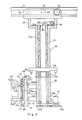
rod conveying apparatus 32 is unloading amonocrystal rod 22 from apull chamber 21; - Fig. 2 is a partial cross sectional view which illustrates the monocrystal
rod conveying apparatus 32 in a conveying state; - Fig. 3 is a plan view which illustrates a finger drive portion 51B;
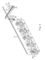
- Fig. 4 is a perspective view which illustrates the overall structure of the monocrystal
rod conveying apparatus 32 and the portion relating to it; - Fig. 5 is a flow chart which illustrates the sequence of conveying the
monocrystal rod 22; and - Figs. 6A to 6H illustrate the operation which corresponds to Fig. 4.
- A preferred embodiment of the present invention will now be described with reference to the drawings.
- As shown in Fig. 4, there are a row of monocrystal pulling up
devices 10 to 14 disposed at predetermined intervals in a factory. Each of the monocrystal pulling updevices 10 to 14 is arranged in such a manner that a pull-chamber 21 is concentrically formed with an opening formed in the upper portion of amain chamber 20 which includes a quarts crusible or the like. A grownmonocrystal rod 22 is accommodated in thepull chamber 21 while being suspended from a pulling wire. As shown in Fig. 1, thepull chamber 21 has a shuttingdoor 24 having awindow 23 formed therein. - As shown in Fig. 4, a
conveyer 30 is arranged in a direction perpendicular to the direction of the row of the monocrystal pulling updevices 10 to 14, theconveyer 30 being disposed by the side of the monocrystal pulling updevice 14. - A
rail 31 is disposed adjacent to the ceiling of the factory, therail 31 extending along the row of the monocrystal pulling updevices 10 to 14 from a portion diagonally above the monocrystal pulling updevice 10 to a portion above theconveyer 30. Atravelling portion 33 of a monocrystalrod conveying device 32 is fastened to therail 31 in such a manner that thetravelling portion 33 is able to move along therail 31. - As shown in Figs. 1 and 2, the upper end surface of an
upper cylinder 36 is, via aneck portion 35, secured to the bottom surface of thetravelling portion 33. Abearing 36A is fixed to the inner surface of theupper cylinder 36 which is vertically placed. The bearing 36A has a key 36a projecting inwardly and formed in the axial direction of thebearing 36A. On the other hand, a key seat extending in the axial direction of anelevational shaft 37 is formed in the surface of theelevational shaft 37, the key seat being formed to correspond to the above-describedkey 36a. In order to restrict the rotation of theelevational shaft 37 and to enable it to desirably move upward/downward, theelevational shaft 37 is inserted into thebearing 36A in a state where the key 36a is fitted within the above-described key seat. A gearedmotor 38 having the output shaft, to which a take-up drum is fastened, is secured to the inside portion of theneck portion 35. Furthermore, apulley 38a is journalled in theneck portion 35 and a wire 36b is arranged in such a manner that it is wound around the take-up drum and the terminative end of thewire 38b is secured to the central portion of the upper end surface of theelevational shaft 37 via thepulley 38a. As a result, when the gearedmotor 38 is rotated forward/reversely, theelevational shaft 37 is not rotated, but is moved upward/downward. - A
lower cylinder 39 havingbearings 39a at the two end portions thereof is fastened around the lower portion of theelevational shaft 37 in such a manner that thelower cylinder 39 can be rotated with respect to the position of theelevational shaft 37 and its vertical movement is prohibited. A gearedmotor 40 is fastened to thelower cylinder 39 in such a manner that agear 40a secured to the output shaft of the gearedmotor 40 is engaged with agear 40b secured to the bottom end of theelevational shaft 37. As a result, when the gearedmotor 40 is rotated forward/reversely, thelower cylinder 39 is rotated clockwise/counterclockwise with respect to the position of theelevational shaft 37. - An end portion of an
arm cylinder 41 is secured to the outer surface of thelower cylinder 39 in a direction perpendicular to thelower cylinder 39. Anarm shaft 42 perpendicularly secured to aback base plate 44 at an end portion thereof is inserted into thearm cylinder 41. In order to adjust the distance between thelower cylinder 39 and theback base plate 44, amotor cylinder 43 is disposed between the above-described two elements. As a result, when themotor cylinder 43 is expanded/contracted, thearm shaft 42 is moved in the axial direction of thearm cylinder 41. - A
tilt base plate 45 is disposed in front of theback base plate 44, thetilt base plate 45 being placed in parallel with theback base plate 44. Thetilt base plate 45 is journalled by asupport shaft 46 which is horizontally placed in the lower portion of theback base plate 44. An end portion of awire 47 is connected to the top end portion of thetilt base plate 45, thewire 47 being wound around adrum 49 after it has been wound to thepulley 48. Thedrum 49 is rotated by a gearedmotor 50. The above-describedpulley 48, thedrum 49 and the gearedmotor 50 are fastened to the upper portion of theback base plate 44. Therefore, when the gearedmotor 50 is rotated forward/reversely, the tilt base pale 45 is rotated around thesupport shaft 46 in a direction in which the same is tilted/stood up. - A
finger drive portion 51A is secured to the lower portion of the front surface of thetilt base plate 45. Furthermore, a finger drive portion 51B is fastened to thetilt base plate 45 above thefinger drive portion 51A in such a manner that the finger drive portion 51B is able to desirably moved in the lengthwise direction of thetilt base plate 45. As shown in Fig. 3, the finger drive portion 51B is arranged in such a manner that afeed screw 522 is, by means of a thread formed on the surface thereof, inserted into anut 521 secured to the back side of aframe 510. As shown in Fig. 2, thefeed screw 522 is journalled by thetilt base plate 45 in such a manner that thefeed screw 522 is rotated by a gearedmotor 52. As shown in Fig. 3, achannel 523 is secured to the central portion on the back side of theframe 510 in parallel with thefeed screw 522, thechannel 523 being engaged with aguide rail 524 secured to thetilt base plate 45. Therefore, the vertical position of the finger drive portion 51B can be adjusted in accordance with the length of themonocrystal rod 22 by the gearedmotor 52 fastened to thetilt base plate 45. - A
geared motor 512 is secured to the side portion of the back side of theframe 510, the gearedmotor 512 having an output shaft to which aspur gear 513 is secured. On the other hand, afeed screw 514 having a right-hand screw 514a on either portion thereof and a left-hand screw 514b on another portion thereof is horizontally journalled in front of theframe 510. Furthermore, aspur gear 516, which is engaged with thespur gear 513, is secured to an end of thefeed screw 514 via a torque limiter 515. Anut 517 is received by the right-hand screw 514, while anut 518 is received by the left-hand screw 514b. A guide rod (omitted from illustration) is inserted into the above-describednuts feed screw 514. The base portions of holdingfingers corresponding nuts motor 512 is rotated forward/reversely, the holdingfingers motor 512 is rotated forward and themonocrystal rod 22 is thereby held by the holdingfingers monocrystal rod 22 is held with predetermined force. Since the thus arranged approaching/moving away mechanism and the holding mechanism are similarly provided for the finger drive portion 51B, the descriptions about them are omitted here. - As shown in Fig. 2, a
flange 55 is secured to theelevational shaft 37 at the uppermost position of thelower cylinder 39. Although omitted from Fig. 1, twopins 56, each of which has a pointed front end, are formed on the lower surface of the two end portions of theflange 55 in such a manner that the twopins 56 project downward. On the other hand, as shown in Fig. 4, a projectingtag 25 is formed in such a manner that it projects from the support frame of each of the monocrystal pulling updevices 10 to 14, thetag 25 having holes 26 (see Fig. 1) which correspond to the above-described pins 56 (the monocrystal pulling updevice 10 shown in Fig. 1 is omitted from illustration). Similarly, aframe 15 having the same shape as the above-described support frame of each of the monocrystal pulling updevices 10 to 14 is disposed adjacently to theconveyer 30 on the extension of the row of the monocrystal pulling updevices 10 to 14. The projectingtag 25 is formed in such a manner that thetag 25 projects from theframe 15, thetag 25 having holes formed to correspond to thepins 56. - As shown in Fig. 4,
command transmitting devices 60 to 64 are disposed in the side portions of the corresponding monocrystal pulling updevices 10 to 14, thecommand transmitting devices 60 to 64 being connected to asignal cable 66 which is arranged along therail 31. On the other hand, amagnetic detector 67 is secured to the inner surface of the travellingportion 33 at a position adjacent to thesignal line 66. Themagnetic detector 67 is connected to a control unit 68 (see Fig. 1) fastened to the travellingportion 33. The above-describedgeared motors motor cylinder 43 are connected to thecontrol unit 68. Thecontrol unit 68 receives signals transmitted from thecommand transmitting devices 60 to 64 via thesignal cable 66 and themagnetic detector 67 so as to control the gearedmotors - In accordance with each of the above-described operations, limit switches (omitted from illustration) for detecting the positions, at which the operations are respectively stopped, are disposed in such a manner that they are electrically connected to the
control unit 68. - Then, the control sequence of the
control unit 68 will now be described with reference to Fig. 5. First, the monocrystalrod conveying apparatus 32 is positioned above theconveyer 30 to wait the operation start.
(100) Thecontrol unit 68 waits for an issue of each of the carry-out commands from thecommand transmitting devices 60 to 64. - After an operator has confirmed that the
monocrystal rod 22 had been grown, the same had been accommodated in thepull chamber 21 and a gate disposed between themain chamber 20 and thepull chamber 21 had been closed, the operator opens the shuttingdoor 24 before the operator issues a conveying command to thecontrol unit 67 by operating a switch of the command transmitting device 6i (hereinafter i = 0 to 4). When thecontrol unit 68 receives the conveying command thus-issued,
(101) It turns on the gearedmotor 34 so as to cause the monocrystalrod conveying device 32 to travel to the position which corresponds to the monocrystal pulling up device 1i which is the subject of the issued conveying command. As a result, a state shown in Fig. 6A is realized.
(102) The gearedmotor 38 is turned on so that thelower cylinder 39 is moved downward to its lowermost position. As a result, a state shown in Fig. 6B is realized. At this time, thepins 56 are fitted within theholes 26 formed in thetag 25 so that thelower cylinder 39 is stabilized.
(103) The gearedmotor 40 is turned on so as to rotate thelower cylinder 39 toward the monocrystal pulling up device 1i by an angular degree of 90°. As a result, as shown in Fig. 6C, receivingfingers fingers monocrystal rod 22.
(104) The gearedmotor 43 is turned on so as to project thearm shaft 43 toward thearm cylinder 41 so that a state shown in Fig. 6D is realized. As a result, the receivingfingers fingers pull chamber 21 so that the direction of the center line, in which themonocrystal rod 22 is held, is made coincide with the direction in which the wire, which is suspending themonocrystal rod 22, is hung. In this state, the operator operates the switch so as to downward move themonocrystal rod 22. As a result, the lower portion of themonocrystal rod 22 is introduced into and held between the receivingfingers monocrystal rod 22 is received.
(105) The holdingfingers monocrystal rod 22. In this state, the operation is temporarily stopped. The operator separates the reduced portion at the upper end portion of themonocrystal rod 22 by cutting before the operator operates the switch of the command transmitting device 6i so as to operate the monocrystalrod conveying apparatus 32.
(106) Thecontrol unit 68 turns on the gearedmotor 43 so as to return thearm shaft 43 so that a state shown in Fig. 6E is realized.
(107) The gearedmotor 40 is turned on so as to rotate thelower cylinder 39 around theelevational shaft 37 in the original direction by an angle of 90° so that a state shown in Fig. 6F is realized.
(108) The gearedmotor 38 is turned on so as to move thelower cylinder 39 to its uppermost position so that a state shown in Fig. 6G is realized.
(109) The gearedmotor 34 is turned on so as to make the monocrystalrod conveying apparatus 32 travel to a position above theconveyer 30.
(110) The gearedmotor 38 is turned on so as to move thelower cylinder 39 to its lowermost position. At this time, thepins 56 are fitted within the holes formed in thetag 25 so that thelower cylinder 39 is stabilized.
(111) The gearedmotor 40 is turned on so as to rotate thelower cylinder 39 around theelevational shaft 37 toward the forward position of theconveyer 30 by an angle of 90°.
(112) The gearedmotor 50 is turned on so as to rotate thetilt base plate 45 by an angle of 90° around thesupport shaft 46 in the tilting direction so that a state shown in Fig. 6H is realized. At this time, the movement of theconveyer 30 is stopped.
(113) The distance between the receivingfingers fingers monocrystal rod 22. As a result, themonocrystal rod 22 is placed on theconveyer 30.
(114) The gearedmotor 50 is turned on so as to rotate thetilt base plate 45 around thesupport shaft 46 by an angle of 90° in the standing direction.
(115) The gearedmotor 40 is turned on so as to rotate thelower cylinder 39 by an angle of 90° around theelevational shaft 37 toward the original position.
(116) The gearedmotor 38 is turned on so as to upward move thelower cylinder 39 to its uppermost position. Simultaneously, the distance between the receivingfingers - The present invention may include a variety of modifications.
- For example, although the above-described embodiment is made about the structure in which the monocrystal pulling up device is the pulling up device arranged to act in accordance with the CZ method, the present invention may be applied to a monocrystal pulling device arranged to act in accordance with the FZ method.
- Furthermore, the best mode of the structure is to dispose the
rail 31 serving as the guide means adjacent to the ceiling. However, it may be disposed on the floor. - Although the invention has been described in its preferred form with a certain degree of particularly, it is understood that the present disclosure of the preferred form has been changed in the details of construction and the combination and arrangement of parts may be resorted to without departing from the spirit and the scope of the invention as hereinafter claimed.
Claims (8)
- A monocrystal rod conveying apparatus (32) for taking out monocrystal rods (22) grown in a plurality of monocrystal pulling up devices (10 to 14) disposed in series and conveying them,
said monocrystal rod conveying apparatus comprising:
guide means (31) disposed along a plurality of said monocrystal pulling up devices;
a traveling portion (33, 34) for travelling along said guide means;
a body portion (35 to 40) an end portion of which is fixed to said travelling portion;
a hand portion (51A to 54B) for holding/releasing said monocrystal rod;
a movable base portion (44 to 50) for supporting said hand portion; and
an expansion portion (41 to 43) arranged in such a manner that its end portion is fastened to said body portion and another end portion is fastened to said movable base portion, said expansion portion being capable of changing the distance between said body portion and said movable base. - A monocrystal rod conveying apparatus according to Claim 1, wherein said body portion includes:
a base portion (35 to 38) fixed to said travelling portion; and
a rotational portion (39, 40) capable of rotating around a vertical shaft with respect to the position of said base portion,
said end portion of said expansion portion being fastened to said rotational portion. - A monocrystal rod conveying apparatus according to Claim 2, wherein said base portion is arranged in such a manner that its lower portion is in the form of a shaft (37) and said rotational portion has a lower cylinder (39) into which said shaft is inserted, said lower cylinder being capable of rotating around said shaft.
- A monocrystal rod conveying apparatus according to Claim 3, wherein said movable base includes:
a back base (44) fixed to said other end portion of said expansion portion; and
a tilt base (45) to which said hand portion is fastened, said tilt base being fastened in such a manner that it is capable of rotating around a horizontal shaft in the lower portion with respect to the position of said back base,
said hand portion (51A to 54B) being provided for said tilt base. - A monocrystal rod conveying apparatus according to Claim 4, wherein said guide means (31) is a rail (31) disposed to the ceiling side of a factory.
- A monocrystal rod conveying apparatus according to Claim 4, wherein said body portion is arranged in such a manner that said rotational portion (39 and 40) is able to move vertically with respect to said base portion (35 to 38).
- A monocrystal rod conveying apparatus according to Claim 6, wherein said base portion (35 to 38) is arranged in such a manner that the upper portion of said shaft (37) is inserted into an upper cylinder (36), said shaft being capable of moving in an axial direction in said upper cylinder.
- A monocrystal rod conveying apparatus according to Claim 4, wherein said hand portion (51A to 54B) includes:
receiving fingers (53A and 53B) into which a cone portion formed in the lower portion of said monocrystal rod (22), which has been placed perpendicularly, is inserted, said receiving fingers (53A and 53B) receiving said cone portion; and
holding fingers for holding the straight body portion of said monocrystal rod.
Applications Claiming Priority (2)
| Application Number | Priority Date | Filing Date | Title |
|---|---|---|---|
| JP138902/90 | 1990-05-28 | ||
| JP2138902A JP2605164B2 (en) | 1990-05-28 | 1990-05-28 | Single crystal rod unloading device and transport method thereof |
Publications (2)
| Publication Number | Publication Date |
|---|---|
| EP0460477A1 true EP0460477A1 (en) | 1991-12-11 |
| EP0460477B1 EP0460477B1 (en) | 1994-08-31 |
Family
ID=15232801
Family Applications (1)
| Application Number | Title | Priority Date | Filing Date |
|---|---|---|---|
| EP91108514A Expired - Lifetime EP0460477B1 (en) | 1990-05-28 | 1991-05-25 | Monocrystal rod conveying apparatus |
Country Status (4)
| Country | Link |
|---|---|
| US (1) | US5176490A (en) |
| EP (1) | EP0460477B1 (en) |
| JP (1) | JP2605164B2 (en) |
| DE (1) | DE69103679T2 (en) |
Cited By (6)
| Publication number | Priority date | Publication date | Assignee | Title |
|---|---|---|---|---|
| WO1997003234A1 (en) * | 1995-07-10 | 1997-01-30 | Seh America, Inc. | Crystal growing cell and installation |
| EP0769577A3 (en) * | 1995-10-19 | 1997-05-07 | Balzers und Leybold Deutschland Holding AG | Process and apparatus for pulling single crystals from a melt in a crucible |
| EP0799913A1 (en) * | 1996-04-03 | 1997-10-08 | Balzers und Leybold Deutschland Holding Aktiengesellschaft | Apparatus for pulling single crystals |
| EP0863230A1 (en) * | 1997-03-06 | 1998-09-09 | Balzers und Leybold Deutschland Holding AG | Apparatus for handling heavy parts of Czochralski crystal pulling apparatus supported in a frame structure |
| EP4556601A1 (en) | 2023-11-17 | 2025-05-21 | Siltronic AG | Method for removing a rod from a crystal pulling installation |
| DE102024004382A1 (en) | 2024-12-20 | 2026-06-25 | Siltronic Ag | Device and method for pulling a crystal from a crystal pulling system according to Czochralski |
Families Citing this family (4)
| Publication number | Priority date | Publication date | Assignee | Title |
|---|---|---|---|---|
| KR970073915A (en) * | 1996-05-28 | 1997-12-10 | 페. 좀머캄프, 하. 하게도른 | Crystal clamp |
| JPH11129184A (en) | 1997-09-01 | 1999-05-18 | Dainippon Screen Mfg Co Ltd | Substrate processing device and substrate loading / unloading device |
| JP3962684B2 (en) * | 2000-11-06 | 2007-08-22 | サムヤン コーポレイション | Transdermal agent having improved water absorption and adhesion |
| JP4984175B2 (en) * | 2008-12-05 | 2012-07-25 | 株式会社ダイフク | Single crystal rod growth equipment |
Citations (3)
| Publication number | Priority date | Publication date | Assignee | Title |
|---|---|---|---|---|
| US4350560A (en) * | 1981-08-07 | 1982-09-21 | Ferrofluidics Corporation | Apparatus for and method of handling crystals from crystal-growing furnaces |
| GB2116871A (en) * | 1982-03-16 | 1983-10-05 | Vnii Monokristallov | Apparatus for growing single crystals from a melt using the Czochralski method |
| US4523972A (en) * | 1983-11-28 | 1985-06-18 | At&T Technologies, Inc. | Method of and apparatus for handling crystal ingots |
Family Cites Families (13)
| Publication number | Priority date | Publication date | Assignee | Title |
|---|---|---|---|---|
| US3280991A (en) * | 1964-04-28 | 1966-10-25 | Programmed & Remote Syst Corp | Position control manipulator |
| JPS5142567B2 (en) * | 1971-05-15 | 1976-11-16 | ||
| US4005782A (en) * | 1974-03-04 | 1977-02-01 | Engineered Metal Products Company, Inc. | Picker |
| US3951271A (en) * | 1974-05-03 | 1976-04-20 | Mette Klaus Hermann | Robot control device |
| US4132318A (en) * | 1976-12-30 | 1979-01-02 | International Business Machines Corporation | Asymmetric six-degree-of-freedom force-transducer system for a computer-controlled manipulator system |
| US4410494A (en) * | 1981-04-13 | 1983-10-18 | Siltec Corporation | Apparatus for controlling flow of molten material between crystal growth furnaces and a replenishment crucible |
| JPS6041038A (en) * | 1983-08-17 | 1985-03-04 | Ricoh Co Ltd | Two-component diazo copying material |
| JPS60186385A (en) * | 1984-01-30 | 1985-09-21 | 不二輸送機工業株式会社 | Fine adjustment for robot hand |
| GB2198413B (en) * | 1986-11-20 | 1990-01-17 | Shimizu Construction Co Ltd | Transporting robot for semiconductor wafers |
| JP2519459B2 (en) * | 1987-06-23 | 1996-07-31 | 東芝セラミックス株式会社 | Single crystal pulling device |
| SU1491698A1 (en) * | 1987-11-24 | 1989-07-07 | Всесоюзный заочный машиностроительный институт | Balanced manipulator |
| SU1495125A1 (en) * | 1987-12-16 | 1989-07-23 | Фрунзенский политехнический институт | Manipulator arm |
| JP2683675B2 (en) * | 1989-01-26 | 1997-12-03 | 東京エレクトロン株式会社 | Transfer device |
-
1990
- 1990-05-28 JP JP2138902A patent/JP2605164B2/en not_active Expired - Lifetime
-
1991
- 1991-05-24 US US07/705,436 patent/US5176490A/en not_active Expired - Fee Related
- 1991-05-25 DE DE69103679T patent/DE69103679T2/en not_active Expired - Fee Related
- 1991-05-25 EP EP91108514A patent/EP0460477B1/en not_active Expired - Lifetime
Patent Citations (3)
| Publication number | Priority date | Publication date | Assignee | Title |
|---|---|---|---|---|
| US4350560A (en) * | 1981-08-07 | 1982-09-21 | Ferrofluidics Corporation | Apparatus for and method of handling crystals from crystal-growing furnaces |
| GB2116871A (en) * | 1982-03-16 | 1983-10-05 | Vnii Monokristallov | Apparatus for growing single crystals from a melt using the Czochralski method |
| US4523972A (en) * | 1983-11-28 | 1985-06-18 | At&T Technologies, Inc. | Method of and apparatus for handling crystal ingots |
Non-Patent Citations (1)
| Title |
|---|
| IBM TECHNICAL DISCLOSURE BULLETIN, vol. 30, no. 10, March 1988, pages 102-103, Armonk, NY, US; "Silicon crystal removal tool" * |
Cited By (12)
| Publication number | Priority date | Publication date | Assignee | Title |
|---|---|---|---|---|
| WO1997003234A1 (en) * | 1995-07-10 | 1997-01-30 | Seh America, Inc. | Crystal growing cell and installation |
| US5641354A (en) * | 1995-07-10 | 1997-06-24 | Seh America, Inc. | Puller cell |
| US5702522A (en) * | 1995-07-10 | 1997-12-30 | Seh America, Inc. | Method of operating a growing hall containing puller cells |
| US5749967A (en) * | 1995-07-10 | 1998-05-12 | Seh America, Inc. | Puller cell |
| EP0769577A3 (en) * | 1995-10-19 | 1997-05-07 | Balzers und Leybold Deutschland Holding AG | Process and apparatus for pulling single crystals from a melt in a crucible |
| EP0799913A1 (en) * | 1996-04-03 | 1997-10-08 | Balzers und Leybold Deutschland Holding Aktiengesellschaft | Apparatus for pulling single crystals |
| EP0863230A1 (en) * | 1997-03-06 | 1998-09-09 | Balzers und Leybold Deutschland Holding AG | Apparatus for handling heavy parts of Czochralski crystal pulling apparatus supported in a frame structure |
| DE19709212A1 (en) * | 1997-03-06 | 1998-09-10 | Leybold Ag | Device for handling heavy components of a crystal drawing machine supported in a supporting frame according to the Czochralski method |
| US6010569A (en) * | 1997-03-06 | 2000-01-04 | Balzers And Leybold Deutschland Holding Ag | Device for handling heavy components of a crystal puller according to the Czochralski method which is supported in a supporting frame |
| EP4556601A1 (en) | 2023-11-17 | 2025-05-21 | Siltronic AG | Method for removing a rod from a crystal pulling installation |
| DE102024004382A1 (en) | 2024-12-20 | 2026-06-25 | Siltronic Ag | Device and method for pulling a crystal from a crystal pulling system according to Czochralski |
| WO2026132166A1 (en) | 2024-12-20 | 2026-06-25 | Siltronic Ag | Device and method for pulling a crystal from a crystal pulling system using the czochralski method |
Also Published As
| Publication number | Publication date |
|---|---|
| JP2605164B2 (en) | 1997-04-30 |
| JPH0431400A (en) | 1992-02-03 |
| DE69103679T2 (en) | 1995-01-19 |
| EP0460477B1 (en) | 1994-08-31 |
| DE69103679D1 (en) | 1994-10-06 |
| US5176490A (en) | 1993-01-05 |
Similar Documents
| Publication | Publication Date | Title |
|---|---|---|
| US5176490A (en) | Monocrystal rod conveying apparatus | |
| US6186723B1 (en) | Load port | |
| US6677690B2 (en) | System for safeguarding integrated intrabay pod delivery and storage system | |
| US5344275A (en) | Method and apparatus for lifting turning and tilting of containers | |
| JPH06104554B2 (en) | Ceiling self-propelled vehicle | |
| JP2000027035A (en) | Spreading speed control device for open bale opener | |
| EP3834609B1 (en) | Apparatus for dispensing bedding inside of breeding cages for use in pharmaceutical preclinical research centres | |
| IT9003529A1 (en) | DEVICE FOR LOADING REELS IN A PACKAGING MACHINE | |
| US4921180A (en) | Package transferring means for a textile winding machine | |
| JP7398815B2 (en) | dock shelter | |
| US5131437A (en) | Device for retrieving the end of the yarn on a yarn-feed spool | |
| JPH08261391A (en) | manipulator | |
| JP4089009B2 (en) | Transport device | |
| JPH0725457A (en) | Vehicle wheel transfer device | |
| KR102938263B1 (en) | Motor internal insulation paper pull-in device | |
| KR200299319Y1 (en) | Device for automatically withdrawing textured yarn bobbins from within a texturing machine and for loading them onto conveyor members external to said machine | |
| JPS61111524A (en) | Vertical heat-treatment furnace for semiconductor | |
| JPS59156994A (en) | Device for pulling out monocrystal | |
| JP3453847B2 (en) | Spinning machine lifting control | |
| JPH03216403A (en) | Automatic warehouse | |
| JPH07290383A (en) | Industrial robot | |
| SU1404265A1 (en) | Loading device | |
| JP2518448Y2 (en) | Lifting Curtain Lifting Device | |
| KR930008330B1 (en) | Delivering apparatus for coil stock | |
| KR0172964B1 (en) | Automatic winding and exhausting device or method of circular knitting machine |
Legal Events
| Date | Code | Title | Description |
|---|---|---|---|
| PUAI | Public reference made under article 153(3) epc to a published international application that has entered the european phase |
Free format text: ORIGINAL CODE: 0009012 |
|
| AK | Designated contracting states |
Kind code of ref document: A1 Designated state(s): DE FR GB |
|
| 17P | Request for examination filed |
Effective date: 19911109 |
|
| 17Q | First examination report despatched |
Effective date: 19930702 |
|
| GRAA | (expected) grant |
Free format text: ORIGINAL CODE: 0009210 |
|
| AK | Designated contracting states |
Kind code of ref document: B1 Designated state(s): DE FR GB |
|
| ET | Fr: translation filed | ||
| REF | Corresponds to: |
Ref document number: 69103679 Country of ref document: DE Date of ref document: 19941006 |
|
| PLBE | No opposition filed within time limit |
Free format text: ORIGINAL CODE: 0009261 |
|
| STAA | Information on the status of an ep patent application or granted ep patent |
Free format text: STATUS: NO OPPOSITION FILED WITHIN TIME LIMIT |
|
| 26N | No opposition filed | ||
| PGFP | Annual fee paid to national office [announced via postgrant information from national office to epo] |
Ref country code: FR Payment date: 19990511 Year of fee payment: 9 |
|
| PGFP | Annual fee paid to national office [announced via postgrant information from national office to epo] |
Ref country code: GB Payment date: 19990519 Year of fee payment: 9 |
|
| PGFP | Annual fee paid to national office [announced via postgrant information from national office to epo] |
Ref country code: DE Payment date: 19990528 Year of fee payment: 9 |
|
| PG25 | Lapsed in a contracting state [announced via postgrant information from national office to epo] |
Ref country code: GB Free format text: LAPSE BECAUSE OF NON-PAYMENT OF DUE FEES Effective date: 20000525 |
|
| GBPC | Gb: european patent ceased through non-payment of renewal fee |
Effective date: 20000525 |
|
| PG25 | Lapsed in a contracting state [announced via postgrant information from national office to epo] |
Ref country code: FR Free format text: LAPSE BECAUSE OF NON-PAYMENT OF DUE FEES Effective date: 20010131 |
|
| PG25 | Lapsed in a contracting state [announced via postgrant information from national office to epo] |
Ref country code: DE Free format text: LAPSE BECAUSE OF NON-PAYMENT OF DUE FEES Effective date: 20010301 |
|
| REG | Reference to a national code |
Ref country code: FR Ref legal event code: ST |