EP0458523A2 - A method and apparatus for transmitting/receiving signals in a video phone - Google Patents
A method and apparatus for transmitting/receiving signals in a video phone Download PDFInfo
- Publication number
- EP0458523A2 EP0458523A2 EP91304386A EP91304386A EP0458523A2 EP 0458523 A2 EP0458523 A2 EP 0458523A2 EP 91304386 A EP91304386 A EP 91304386A EP 91304386 A EP91304386 A EP 91304386A EP 0458523 A2 EP0458523 A2 EP 0458523A2
- Authority
- EP
- European Patent Office
- Prior art keywords
- video signal
- frequency
- signal
- video
- transmission line
- Prior art date
- Legal status (The legal status is an assumption and is not a legal conclusion. Google has not performed a legal analysis and makes no representation as to the accuracy of the status listed.)
- Granted
Links
Images


Classifications
-
- H—ELECTRICITY
- H04—ELECTRIC COMMUNICATION TECHNIQUE
- H04N—PICTORIAL COMMUNICATION, e.g. TELEVISION
- H04N7/00—Television systems
- H04N7/14—Systems for two-way working
- H04N7/141—Systems for two-way working between two video terminals, e.g. videophone
- H04N7/147—Communication arrangements, e.g. identifying the communication as a video-communication, intermediate storage of the signals
-
- H—ELECTRICITY
- H04—ELECTRIC COMMUNICATION TECHNIQUE
- H04N—PICTORIAL COMMUNICATION, e.g. TELEVISION
- H04N7/00—Television systems
- H04N7/14—Systems for two-way working
- H04N7/141—Systems for two-way working between two video terminals, e.g. videophone
- H04N7/148—Interfacing a video terminal to a particular transmission medium, e.g. ISDN
Definitions
- the present invention relates in general to a method and an apparatus for transmitting and receiving signals in a video phone, and more particularly to a method and an apparatus for transmitting and receiving a voice signal simultaneously with a video signal via a single transmission line in the video phone.
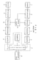
- Fig. 1 is a block diagram of a generic construction of a conventional apparatus for transmitting and receiving signals in the video phone employing the telephone line.
- the conventional apparatus comprises a camera 1 for taking an image of a caller, an A/D converter 2 for digitizing a video signal outputted from the camera 1, a first memory unit 3 for storing an output signal from the A/D converter 2, a modulator 4 for modulating the signal, or digitized video signal, stored in the first memory unit 3, a first amplifier 5 for amplifying an output signal from the modulator 4 by a predetermined amplification degree, a second amplifier 8 for amplifying a digitized video signal from a counterpart by a predetermined amplification degree, a demodulator 9 for demodulating an output signal from the second amplifier 8, a second memory unit 10 for storing an output signal from the demodulator 9, a D/A converter 11 for converting the signal, or digitized video signal from the counterpart, stored in the second memory unit 10 into an analog signal to output the analog signal,
- the image of the face of the caller, taken by the camera 1, is an analog signal, which is converted by the A/D converter 2 upon receiving a clock from the control circuit 14, into a digital signal to be stored into the first memory unit 3. Also, the control circuit 14 feeds address and control signals to the first memory unit 3. Data stored in the first memory unit 3 is modulated suitably to a line characteristic by the modulator 4 and then is transferred through the first amplifier 5 to the switching circuit 6, which sends the data out over the telephone line, thereby enabling the video signal to be sent to the counterpart.
- the switching circuit 6 transfers the digitized video signal to the second amplifier 8, as a receiving amplifier, and then to the demodulator 9.
- the demodulated signal from the demodulator 9 is stored into the second memory unit 10 under the control of the control circuit 14 and the signal stored in the second memory unit 10 is then converted by the D/A converter 11 into an analog signal to be displayed on the monitor 12.
- the caller can see the face of the counterpart through the monitor.
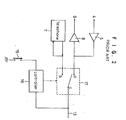
- Fig. 2 is a detailed circuit diagram of a part P including the telephone 7 and the switching circuit 6, shown in Fig. 1.
- a controller 16 upon pushing a transmitting switch 15 under the condition that the caller would like to send his image to the counterpart while thecaller telephones a message to the counterpart, a controller 16 outputs a control signal to a switch 17.
- the terminal c of the switch 17 is connected to the terminal a in the transmission and reception of the video signal, while to terminal b in the voice telephone call.
- no transmission and reception of the voice signal can be performed under the condition of the transmission and reception of the video signal.
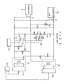
- Fig. 3 is a circuit diagram of an embodiment of the conventional apparatus for transmitting and receiving signals in the video phone employing the telephone line
- the conventional apparatus is shown to comprise a transmitting transformer 18 connected between the standard telephone 13 and telephone 7, for interfacing the video signal to be transmitted, a receiving transformer 19 connected between the standard telephone 13 and telephone 7 for interfacing the video signal to be received, a first video signal processing circuit 20 for processing the video signal to be transmitted, a second video signal processing circuit 21 for processing the video signal to be received, a relay 22 including two relay switches 22a and 22b, for operating to send only one of the voice signal and the video signal via the telephone line 13, and a controller 23 for applying a drive control signal to the relay 22 and the first and the second video signal processing circuits 20 and 21.
- the reference numeral 24 designates a surge voltage absorbing triac, R1 to R7 resistors and C1 to C7 capacitors.
- the controller 23 then operates to control the first video signal processing circuit 20 to send the video signal via the telephone line 13.
- the controller 23 operates to control the second video signal processing circuit 21 to receive the video signal, even in the reception of the video signal from the counterpart, similarly to the case of the transmission of the video signal.
- the conventional apparatus cannot transmit and receive the voice signal simultaneously with the video signal via the single transmission line in the video phone, thereby resulting in the stand-by status of the one side in the course of transmission of the video signal from the other side.
- the transmission and reception of the video signal between the caller and the counterpart by the conventional apparatus as stated above takes too much time.
- an apparatus for transmitting and receiving the voice signal simultaneously with the video signal via the single transmission line comprising: filtering means connected between said telephone and said transmission line, for inputting the voice signal from either said telephone or said transmission line and passing only voice signal with a frequency region below a first frequency set within a frequency band of said transmission line; video signal receiving means for discriminating if a carrier frequency in the video signal being sent via said transmission line from a counterpart is which of a second frequency or a third frequency set within said frequency band of said transmission line, demodulating the video signal by one of said second and third frequencies depending upon the discriminated result, and outputting the demodulated video signal to said displaying monitor; video signal transmitting means for inputting the video signal from said self-camera, modulating the video signal
- a method of transmitting and receiving the voice signal simultaneously with the video signal via the single transmission line comprising the steps of: turning on power if said hook switch of said telephone is turned from an original ON state into an OFF state; designating a second frequency set within a frequency band of said transmission line as a carrier frequency of the video signal for transmission and a third frequency set within said frequency band of said transmission line as a carrier frequency of the video signal for reception upon receiving a control signal for transmission of the video signal, modulating and demodulating the video signals to be transmitted and received, in accordance with said designated frequencies, transmitting and receiving the modulated and demodulated video signals, and turning off power after the sending of the modulated and demodulated video signals is finished; designating the other of said second frequency and said
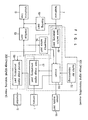
- the apparatus for transmitting and receiving signals in the video phone in accordance with the present invention is shown to comprise a filter 50 connected between a telephone 7 and a telephone line 13, for inputting a voice signal from either telephone 7 or telephone line 13 and passing only voice signal with a frequency region below a first frequency f1 set within a frequency band of the telephone line 13.
- the apparatus comprises a hook switch sensor 51 for sensing ON/OFF states of a hook switch (not shown), a transmitting switch 52 for outputting a control signal for transmission of video signal, an interface unit 53 for separately outputting video signals to be received and transmitted, a frequency discriminator 54 for discriminating if a carrier frequency in the video signal to be received is which of a second frequency f2 or a third frequency f3 set within the frequency band of the telephone line 13 and outputting a acknowledge signal depending upon the discriminated result, a power supply 55 for supplying power required by the apparatus, and a microprocessor 56 for inputting output signals from the hook switch sensor 51, the transmitting switch 52 and the frequency discriminator 54 and outputting a plurality of control signals necessary to the operation of the apparatus.
- the apparatus according to the present invention is also provided with a first and a second video signal processing circuits 57 and 58.
- the first video signal processing circuit 57 inputs the video signal from a self-camera 1 and operates to send the inputted video signal to the counterpart. Namely, the first video signal processing circuit 57 modulates and band-pass filters the inputted video signal by a predetermined frequency in response to the control signal from the microprocessor 56 and outputs such modulated and band-pass filtered video signal to the interface unit 53.
- the second video signal processing circuit 58 operates to display the video signal inputted through the interface unit 53 on a monitor 12. That is, the second video signal processing circuit 58 demodulates and band-pass filters the inputted video signal by a predetermined frequency in response to the control signal from the microprocessor 56 and outputs such demodulated and band-pass filtered video signal to the monitor 12.
- the power-ON/OFF of the whole system is controlled by an output signal from the hook switch sensor 51.
- the output signal from the hook switch sensor 51 allows the microprocessor 56 to drive the grower supply 55 to turn on power.
- the microprocessor 56 instructs the power supply 55 to turn off power.
- the microprocessor 56 designates the second frequency f2 as shown in Fig. 5b as the carrier frequency for modulation.
- the video signal from the counterpart can be modulated and transmitted only by the third frequency f3 as shown in Fig. 5b.
- the hook switch sensor With the output signal from the hook switch sensor, it is possible to recognize the end state of the transmission and reception of the image data, or video signal. That is, because the caller hangs up a handset if his telephone call to the counterpart is finished, the hook switch of the telephone 7 is turned on, the state of which is sensed by the hook switch sensor 51, thereby allowing the microprocessor 56 to turn off power. As a result, the image telephone call between them is finished.
- the microprocessor 56 perceives such state from the output signal from the frequency discriminator 54 and designates the third frequency f3 as shown in Fig. 5b as the carrier frequency of the video signal for transmission, since the carrier frequency of the video signal to be received is the second frequency f2 as shown in Fig. 5b.
- one first transmitting the video signal first selects the second frequency f2 as the carrier frequency.
- a video signal transmitting means 100 is shown to include the hook switch sensor 51, the transmitting switch 52, the microprocessor 56 and the first video signal processing circuit 57.
- a video signal receiving means 200 includes the hook switch sensor 51, the frequency discriminator 54, the microprocessor 56 and the second video signal processing circuit 58.
- Fig. 5b illustrates frequency spectrum characteristics of the transmission line according to the present invention.
- the telephone line has the frequency band limited to 3.4 KHz as shown in Fig. 5a.
- the second frequency carrier is designated at 2 KHz part and the third frequency carrier is designated at 2.8 KHz part, so that the voice signal and the video signal can be simultaneously transmitted and received. Therefore, the voice signal and the video signal modulated at the first frequency or the second frequency can be simultaneously seen and heard.
- the microprocessor 56 is shown to include a first microprocessor 56a, as a transmitting microprocessor, for providing a control signal for the first video signal processing circuit 57 and a second microprocessor 56b, as a receiving microprocessor, for providing a control signal for the second video signal processing circuit 58.
- the first video signal processing circuit 57 includes a timing signal generator 61 for generating a clock signal, an A/D converter 62 for inputting the video signal from the self-camera 1 and digitizing the inputted video signal to be transmitted, in response to the clock signal from the timing signal generator 61, a memory controller 63 for generating read/wright select and address signals in response to the control signal from the first microprocessor 56a and the clock signal from the timing signal generator 61, a memory unit 64 for storing the digitized video signal from the A/D converter 62 in an addressed location in response to the read/wright select and address signals from the memory controller 63, a carrier generator 65 for generating the second frequency f2 carrier or the third frequency f3 carrier as shown in Fig.
- a modulator 66 for modulating the image data, or digitized video signal stored in the memory unit 66 by the frequency carriers generated by the carrier generator 65, a first amplifier 67 for amplifying an output signal from the modulator 66 by a predetermined amplification degree, a first band pass filter 68 for passing only video signal with the second frequency f2 component to the interface unit 53, a second band pass filter 69 for passing only video signal with the third frequency f3 component to the interface unit 53, and a first switching circuit 70 for selectively outputting an output signal from the first amplifier 67 to the first band pass filter 68 or the second band pass filter 69 in response to the control signal from the first microprocessor 56a.
- the second video signal processing circuit 58 includes a third band pass filter 71 for passing only video signal with the second frequency f2 component, a fourth band pass filter 72 for passing only video signal with the third frequency f3 component, a second switching circuit 73 for selectively outputting the video signal from the counterpart, inputted through the interface unit 53, to the third band pass filter 71 or the fourth band pass filter 72 in response to the control signal from the second microprocessor 56b, a second amplifier 74 for amplifying the video signal from the counterpart, passed through the third band pass filter 71 or the fourth band pass filter 72, by a predetermined amplification degree, a demodulator 75 for inputting an output signal from the second amplifier 74 and demodulating the inputted signal in response to the control signal from the second microprocessor 56b, and a D/A converter 76 for converting an output signal from the demodulator 75 into an analog signal and outputting the analog signal to the displaying monitor 12.
- a third band pass filter 71 for passing only video signal with the second frequency f2 component
- the interface unit 53 also includes a transmitting and receiving transformer 77 adapted for inputting and outputting simultaneously the video signals to be transmitted and received and a hybrid circuit 78 adapted for separately outputting the video signals to be received and transmitted, inputted through the transmitting and receiving transformer 77.
- the frequency discriminator 54 is also provided with two tone decoders 54a and 54b for discriminating the frequency component of the video signal from the counterpart.
- the first microprocessor 56a for transmission outputs the control signal to the power supply 55 to turn on it.
- the A/D converter 62 then converts the video signal outputted from the self-camera 1 into a digital signal in response to the clock signal supplied from the timing signal generator 61.
- the video signal digitized by the A/D converter 62 is stored in the location of the memory unit 64 corresponding to a predetermined address under the control of the memory controller 63, which generates the address signal and the read/wright select signals.
- the first microprocessor 56a for transmission designates the second frequency f2 as the carrier signal from the carrier generator 65, so that an output signal from the memory unit 64, or the digitized video signal stored in the memory unit 64 can be modulated by the carrier of the second frequency f2 component by the modulator 66.
- the modulated video signal to be transmitted is amplified by the predetermined amplification degree by the first amplifier 67 and then transferred to the first band pass filter 68 by the switching operation of the first switching circuit 70, the switching control of which is performed by the first microprocessor 56a for transmission.
- the modulated video signal is filtered by the first band pass filter 68 allowing only second frequency f2 component to be inputted by the interface unit 53, and then sent to the counterpart via the telephone line 13. Simultaneously. the video signal sent from the counterpart is inputted through the same interface unit 53.
- the second microprocessor 56b perceives whether the frequency component received is the second frequency f2 or the third frequency f3 in accordance with output signals from the tone decoders 54a and 54b in the frequency discriminator 54 and then controls the second swithig circuit 73 for frequency selection in accordance with the discriminated result.
- the video signal is inputted to the third band pass filter 71; if the carrier of the video signal received is the third frequency f3 component, the video signal is inputted to the fourth band pass filter 72.
- the video signal filtered in accordance with the frequency component as mentioned above is amplified by the predetermined amplification degree by the second amplifier 74, demodulated by the demodulator 75 under the control of the second microprocessor 56b and then converted into an analog signal by the D/A converter 76. In result, this analog signal, or video signal is displayed on the monitor 12.
- Fig. 8 is a detailed circuit diagram of a part Q in Fig 7.
- the reference numerals R11 to R24 desigante resistors, C11 to C33 capacitors, 81 to 86 operational amplifiers, 88 triac, K1 to K4 variable resistors and 90 switch.
- the first microprocessor 56a for transmission of video signal outputs a control signal a11 for driving the first switching circuit 70, so that the output signal from the first amplifier 67 can be passed through the first band pass to filter 68.
- the video signal to be transmitted with the second frequency f2 component is outputted to a point r.
- the variable resistor K3 connected to the operational amplifier 83 in the hybrid circuit 78 is adjusted to adjust a signal at a point s.
- the phase of the video signal is once inverted by the operational amplifier 83 and again inverted by the operational amplifier 85.
- the video signal is sent out over the telephone line 13 by the transmitting and receiving transformer 77.
- the voice signal being transmitted and received is passed through the filter 50 connected to the telephone 7, thereby allowing only voice signal with frequency component below the first frequency f1 to be filtered. Therefore, the voice and video signals can be simultaneously sent via the telephone line 13.
- variable resistor K4 is adjusted such that the sum of the video signals at the point s, or output of the operational amplifier 83, and at the point t, or output of the operational amplifier 84, can become zero. Therefore, the video signal transmitted can be never received reversely.
- the video signal sent from the counterpart is not inputted to the operational amplifiers 83 and 84, but to the second switching circuit 73 via the operational amplifier 85, from the transmitting and receiving transformer 77.
- the switching circuit 73 is switched by a control signal a12 from the second microprocessor 56b to transfer the video signal to be received, to the third band pass filter 71. That is, if the video signal to be transmitted is to have the second frequency f2 component, thus the video signal to be received is to have the third frequency f3 component.
- the apparatus in accordance with the present invention can provide advantages as follows:
- the transmission time can be shorted by the simultaneous transmission and reception of the video signal between the cal ler and the counterpart.
Abstract
Description
- The present invention relates in general to a method and an apparatus for transmitting and receiving signals in a video phone, and more particularly to a method and an apparatus for transmitting and receiving a voice signal simultaneously with a video signal via a single transmission line in the video phone.
- Generally, there has been employed a telephone line as a transmission line in a video phone.
- Fig. 1 is a block diagram of a generic construction of a conventional apparatus for transmitting and receiving signals in the video phone employing the telephone line. As shown in the drawing, the conventional apparatus comprises a
camera 1 for taking an image of a caller, an A/D converter 2 for digitizing a video signal outputted from thecamera 1, afirst memory unit 3 for storing an output signal from the A/D converter 2, amodulator 4 for modulating the signal, or digitized video signal, stored in thefirst memory unit 3, afirst amplifier 5 for amplifying an output signal from themodulator 4 by a predetermined amplification degree, a second amplifier 8 for amplifying a digitized video signal from a counterpart by a predetermined amplification degree, ademodulator 9 for demodulating an output signal from the second amplifier 8, asecond memory unit 10 for storing an output signal from thedemodulator 9, a D/A converter 11 for converting the signal, or digitized video signal from the counterpart, stored in thesecond memory unit 10 into an analog signal to output the analog signal, or video signal to amonitor 12, acontrol circuit 14 connected between the first and thesecond memory units D converter 2, for feeding desired address and control signals to them, astandard telephone 7, and a switching circuit 6 connected among an output terminal of thefirst amplifier 5, an input terminal of the second amplifier 8, thetelephone 7 and atelephone line 13, for selectively connecting the output terminal of thefirst amplifier 5, the input terminal of the second amplifier 8 or thetelephone 7 to thetelephone line 13 in accordance with some conditions. - The operation of the conventional apparatus with the above-mentioned construction will now be described.
- The image of the face of the caller, taken by the
camera 1, is an analog signal, which is converted by the A/D converter 2 upon receiving a clock from thecontrol circuit 14, into a digital signal to be stored into thefirst memory unit 3. Also, thecontrol circuit 14 feeds address and control signals to thefirst memory unit 3. Data stored in thefirst memory unit 3 is modulated suitably to a line characteristic by themodulator 4 and then is transferred through thefirst amplifier 5 to the switching circuit 6, which sends the data out over the telephone line, thereby enabling the video signal to be sent to the counterpart. - On the other hand, upon receiving the image data, or digitized video signal, from the counterpart, the switching circuit 6 transfers the digitized video signal to the second amplifier 8, as a receiving amplifier, and then to the
demodulator 9. The demodulated signal from thedemodulator 9 is stored into thesecond memory unit 10 under the control of thecontrol circuit 14 and the signal stored in thesecond memory unit 10 is then converted by the D/A converter 11 into an analog signal to be displayed on themonitor 12. Thus, the caller can see the face of the counterpart through the monitor. - Fig. 2 is a detailed circuit diagram of a part P including the
telephone 7 and the switching circuit 6, shown in Fig. 1. As shown in the drawing, upon pushing a transmittingswitch 15 under the condition that the caller would like to send his image to the counterpart while thecaller telephones a message to the counterpart, acontroller 16 outputs a control signal to aswitch 17. A terminal c of theswitch 17, having been connected to a terminal b during voice telephone call, is thus connected to a terminal a to send the video signal out to the counterpart via thetelephone line 13, similarly to the case that the counterpart would like to send his image to the caller. - Namely, the terminal c of the
switch 17 is connected to the terminal a in the transmission and reception of the video signal, while to terminal b in the voice telephone call. As a result, no transmission and reception of the voice signal can be performed under the condition of the transmission and reception of the video signal. - Referring next to Fig. 3 which is a circuit diagram of an embodiment of the conventional apparatus for transmitting and receiving signals in the video phone employing the telephone line, the conventional apparatus is shown to comprise a transmitting
transformer 18 connected between thestandard telephone 13 andtelephone 7, for interfacing the video signal to be transmitted, a receivingtransformer 19 connected between thestandard telephone 13 andtelephone 7 for interfacing the video signal to be received, a first videosignal processing circuit 20 for processing the video signal to be transmitted, a second videosignal processing circuit 21 for processing the video signal to be received, arelay 22 including tworelay switches telephone line 13, and acontroller 23 for applying a drive control signal to therelay 22 and the first and the second videosignal processing circuits reference numeral 24 designates a surge voltage absorbing triac, R1 to R7 resistors and C1 to C7 capacitors. - The operation of the conventional apparatus with the above-mentioned construction will now be described.
- When, normal times, the caller is to telephone a message to the counterpart, one lines L2 and T2 of the
telephone line 13 and thetelephone 7 are connected directly to each other and the other lines L1 and T1 are connected via the transmittingtransformer 20 to each other, in order to send the voice signal to the counterpart, thereby allowing the telephone call. On the other hand, therelay 22 is driven under the control of thecontroller 23 and states of therelay switches telephone 7, thereby preventing the voice signal from being sent to the counterpart. As a result, it is impossible to send the voice signal to the counterpart. - The
controller 23 then operates to control the first videosignal processing circuit 20 to send the video signal via thetelephone line 13. - On the other hand, the
controller 23 operates to control the second videosignal processing circuit 21 to receive the video signal, even in the reception of the video signal from the counterpart, similarly to the case of the transmission of the video signal. - With the above-mentioned construction, however, the conventional apparatus cannot transmit and receive the voice signal simultaneously with the video signal via the single transmission line in the video phone, thereby resulting in the stand-by status of the one side in the course of transmission of the video signal from the other side. In result, the transmission and reception of the video signal between the caller and the counterpart by the conventional apparatus as stated above takes too much time.
- Therefore, it is an object of the present invention to provide a method and an apparatus for transmitting and receiving a voice signal simultaneously with a video signal via a single transmission line in a video phone between a caller and a counterpart.
- In accordance with one aspect of the present invention, in a video phone for transmitting and receiving a video signal and a voice signal by means of a single transmission line, said video phone having a standard telephone having a hook switch, a displaying monitor and a self-camera, there is provided an apparatus for transmitting and receiving the voice signal simultaneously with the video signal via the single transmission line, said apparatus comprising: filtering means connected between said telephone and said transmission line, for inputting the voice signal from either said telephone or said transmission line and passing only voice signal with a frequency region below a first frequency set within a frequency band of said transmission line; video signal receiving means for discriminating if a carrier frequency in the video signal being sent via said transmission line from a counterpart is which of a second frequency or a third frequency set within said frequency band of said transmission line, demodulating the video signal by one of said second and third frequencies depending upon the discriminated result, and outputting the demodulated video signal to said displaying monitor; video signal transmitting means for inputting the video signal from said self-camera, modulating the video signal with the other of said second and third frequencies differently from said video signal receiving means and outputting the modulated video signal to said transmission line; and interfacing means connected among said transmission line, said video signal receiving means and said video signal transmitting means, for separately outputting the video signals to be received and transmitted.
- In accordance with another aspect of the present invention, in a video phone for transmitting and receiving a video signal and a voice signal by means of a single transmission line, said video phone having a standard telephone having a hook switch, a displaying monitor and a self-camera, there is provided a method of transmitting and receiving the voice signal simultaneously with the video signal via the single transmission line, said method comprising the steps of: turning on power if said hook switch of said telephone is turned from an original ON state into an OFF state; designating a second frequency set within a frequency band of said transmission line as a carrier frequency of the video signal for transmission and a third frequency set within said frequency band of said transmission line as a carrier frequency of the video signal for reception upon receiving a control signal for transmission of the video signal, modulating and demodulating the video signals to be transmitted and received, in accordance with said designated frequencies, transmitting and receiving the modulated and demodulated video signals, and turning off power after the sending of the modulated and demodulated video signals is finished; designating the other of said second frequency and said third frequency as the carrier frequency of the video signal for transmission upon receiving the video signal with one of said second frequency and said third frequency from a counterpart and no control signal for transmission of the video signal, modulating and demodulating the video signals to be transmitted and received, in accordance with said designated frequencies, transmitting and receiving the modulated and demodulated video signals until said hook switch is turned into said ON state, and turning off power after the sending of the modulated and demodulated video signals is finished; and performing only voice telephone call upon receiving no either the control signal for transmission of the video signal or the video signal from the counterpart.
- The above and other objects, features and advantages of the present invention will be more clearly understood from the following detailed description taken in conjunction with the accompanying drawings, in which:
- Fig. 1 is a block diagram of a generic construction of a conventional apparatus for transmitting and receiving signals in a video phone;
- Fig. 2 is a detailed circuit diagram of a part P in Fig 1;
- Fig. 3 is a circuit diagram of an embodiment of the conventional apparatus for transmitting and receiving signals in the video phone;
- Fig. 4 is a block diagram of a construction of an apparatus for transmitting and receiving signals in the video phone in accordance with the present invention;
- Fig. 5a illustrates a general frequency band of a transmission line;
- Fig. 5b illustrates frequency spectrum characteristics of the transmission line according to the present invention;
- Fig. 6 is a flowchart illustrating a method of transmitting and receiving signals in the video phone in accordance with the present invention;
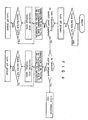
- Fig. 7 is a detailed block diagram of the construction in Fig. 4; and
- Fig. 8 is a detailed circuit diagram of a part Q in Fig 7.
- First, a construction of an apparatus for transmitting and receiving signals in a video phone in accordance with the present invention will be described with reference to Fig. 4.
- In Fig. 4, the apparatus for transmitting and receiving signals in the video phone in accordance with the present invention is shown to comprise a
filter 50 connected between atelephone 7 and atelephone line 13, for inputting a voice signal from eithertelephone 7 ortelephone line 13 and passing only voice signal with a frequency region below a first frequency f1 set within a frequency band of thetelephone line 13. - Also, the apparatus according to the present invention comprises a
hook switch sensor 51 for sensing ON/OFF states of a hook switch (not shown), atransmitting switch 52 for outputting a control signal for transmission of video signal, aninterface unit 53 for separately outputting video signals to be received and transmitted, afrequency discriminator 54 for discriminating if a carrier frequency in the video signal to be received is which of a second frequency f2 or a third frequency f3 set within the frequency band of thetelephone line 13 and outputting a acknowledge signal depending upon the discriminated result, apower supply 55 for supplying power required by the apparatus, and amicroprocessor 56 for inputting output signals from thehook switch sensor 51, the transmittingswitch 52 and thefrequency discriminator 54 and outputting a plurality of control signals necessary to the operation of the apparatus. - The apparatus according to the present invention is also provided with a first and a second video
signal processing circuits signal processing circuit 57 inputs the video signal from a self-camera 1 and operates to send the inputted video signal to the counterpart. Namely, the first videosignal processing circuit 57 modulates and band-pass filters the inputted video signal by a predetermined frequency in response to the control signal from themicroprocessor 56 and outputs such modulated and band-pass filtered video signal to theinterface unit 53. The second videosignal processing circuit 58 operates to display the video signal inputted through theinterface unit 53 on amonitor 12. That is, the second videosignal processing circuit 58 demodulates and band-pass filters the inputted video signal by a predetermined frequency in response to the control signal from themicroprocessor 56 and outputs such demodulated and band-pass filtered video signal to themonitor 12. - Next, the operation of the apparatus with the above-mentioned construction in accordance with the present invention will be described in detail with reference to a flowchart of Fig. 6.
- The power-ON/OFF of the whole system is controlled by an output signal from the
hook switch sensor 51. - Namely, the output signal from the
hook switch sensor 51 allows themicroprocessor 56 to drive thegrower supply 55 to turn on power. On the other hand, if the output signal from thehook switch sensor 51 is not present, themicroprocessor 56 instructs thepower supply 55 to turn off power. - When the transmitting
switch 52 has been pushed first by the transmitting side, or caller at power-ON, themicroprocessor 56 designates the second frequency f2 as shown in Fig. 5b as the carrier frequency for modulation. Thus, the video signal from the counterpart can be modulated and transmitted only by the third frequency f3 as shown in Fig. 5b. - With the output signal from the hook switch sensor, it is possible to recognize the end state of the transmission and reception of the image data, or video signal. That is, because the caller hangs up a handset if his telephone call to the counterpart is finished, the hook switch of the
telephone 7 is turned on, the state of which is sensed by thehook switch sensor 51, thereby allowing themicroprocessor 56 to turn off power. As a result, the image telephone call between them is finished. - On the other hand, if the video signal from the counterpart was sent to the transmitting side before the transmitting
switch 52 is pushed by the transmitting side, themicroprocessor 56 perceives such state from the output signal from thefrequency discriminator 54 and designates the third frequency f3 as shown in Fig. 5b as the carrier frequency of the video signal for transmission, since the carrier frequency of the video signal to be received is the second frequency f2 as shown in Fig. 5b. - Namely, of two video phones, one first transmitting the video signal, first selects the second frequency f2 as the carrier frequency.
- As apparent from the above description, in video phones having been usually employed now, only between products in which frequencies set for modulation are equal to each other the intertransmission of the voice signal and the video signal is enabled.
- Referring again to Fig. 4, a video signal transmitting means 100 is shown to include the
hook switch sensor 51, the transmittingswitch 52, themicroprocessor 56 and the first videosignal processing circuit 57. - Also, a video signal receiving means 200 includes the
hook switch sensor 51, thefrequency discriminator 54, themicroprocessor 56 and the second videosignal processing circuit 58. - Fig. 5b illustrates frequency spectrum characteristics of the transmission line according to the present invention.
- In general, the telephone line has the frequency band limited to 3.4 KHz as shown in Fig. 5a.
- In accordance with the present invention, in the frequency band of the telephone line, only frequency region below 1.5KHz is used for the transmission of the voice signal, the second frequency carrier is designated at 2 KHz part and the third frequency carrier is designated at 2.8 KHz part, so that the voice signal and the video signal can be simultaneously transmitted and received. Therefore, the voice signal and the video signal modulated at the first frequency or the second frequency can be simultaneously seen and heard.
- Turning now to Fig. 7, the
microprocessor 56 is shown to include afirst microprocessor 56a, as a transmitting microprocessor, for providing a control signal for the first videosignal processing circuit 57 and asecond microprocessor 56b, as a receiving microprocessor, for providing a control signal for the second videosignal processing circuit 58. - The first video
signal processing circuit 57 includes atiming signal generator 61 for generating a clock signal, an A/D converter 62 for inputting the video signal from the self-camera 1 and digitizing the inputted video signal to be transmitted, in response to the clock signal from thetiming signal generator 61, amemory controller 63 for generating read/wright select and address signals in response to the control signal from thefirst microprocessor 56a and the clock signal from thetiming signal generator 61, amemory unit 64 for storing the digitized video signal from the A/D converter 62 in an addressed location in response to the read/wright select and address signals from thememory controller 63, acarrier generator 65 for generating the second frequency f2 carrier or the third frequency f3 carrier as shown in Fig. 5b in response to the control signal from thefirst microprocessor 56a, amodulator 66 for modulating the image data, or digitized video signal stored in thememory unit 66 by the frequency carriers generated by thecarrier generator 65, afirst amplifier 67 for amplifying an output signal from themodulator 66 by a predetermined amplification degree, a firstband pass filter 68 for passing only video signal with the second frequency f2 component to theinterface unit 53, a secondband pass filter 69 for passing only video signal with the third frequency f3 component to theinterface unit 53, and afirst switching circuit 70 for selectively outputting an output signal from thefirst amplifier 67 to the firstband pass filter 68 or the secondband pass filter 69 in response to the control signal from thefirst microprocessor 56a. - Also, the second video
signal processing circuit 58 includes a thirdband pass filter 71 for passing only video signal with the second frequency f2 component, a fourthband pass filter 72 for passing only video signal with the third frequency f3 component, asecond switching circuit 73 for selectively outputting the video signal from the counterpart, inputted through theinterface unit 53, to the thirdband pass filter 71 or the fourthband pass filter 72 in response to the control signal from thesecond microprocessor 56b, asecond amplifier 74 for amplifying the video signal from the counterpart, passed through the thirdband pass filter 71 or the fourthband pass filter 72, by a predetermined amplification degree, ademodulator 75 for inputting an output signal from thesecond amplifier 74 and demodulating the inputted signal in response to the control signal from thesecond microprocessor 56b, and a D/A converter 76 for converting an output signal from thedemodulator 75 into an analog signal and outputting the analog signal to the displayingmonitor 12. - The
interface unit 53 also includes a transmitting and receivingtransformer 77 adapted for inputting and outputting simultaneously the video signals to be transmitted and received and ahybrid circuit 78 adapted for separately outputting the video signals to be received and transmitted, inputted through the transmitting and receivingtransformer 77. - The
frequency discriminator 54 is also provided with twotone decoders - Now, the operation of the apparatus with the above-mentioned construction according to the present invention as shown in Fig. 7 will be described in detail.
- First, if the hook switch is turned off, i.e., if the handset is picked up, then in response to the output signal from the
hook switch sensor 51 adapted to sense ON/OFF states of the hook switch, thefirst microprocessor 56a for transmission outputs the control signal to thepower supply 55 to turn on it. The A/D converter 62 then converts the video signal outputted from the self-camera 1 into a digital signal in response to the clock signal supplied from thetiming signal generator 61. The video signal digitized by the A/D converter 62 is stored in the location of thememory unit 64 corresponding to a predetermined address under the control of thememory controller 63, which generates the address signal and the read/wright select signals. - When the transmitting
switch 52 has been pushed, thefirst microprocessor 56a for transmission designates the second frequency f2 as the carrier signal from thecarrier generator 65, so that an output signal from thememory unit 64, or the digitized video signal stored in thememory unit 64 can be modulated by the carrier of the second frequency f2 component by themodulator 66. The modulated video signal to be transmitted is amplified by the predetermined amplification degree by thefirst amplifier 67 and then transferred to the firstband pass filter 68 by the switching operation of thefirst switching circuit 70, the switching control of which is performed by thefirst microprocessor 56a for transmission. - The modulated video signal is filtered by the first
band pass filter 68 allowing only second frequency f2 component to be inputted by theinterface unit 53, and then sent to the counterpart via thetelephone line 13. Simultaneously. the video signal sent from the counterpart is inputted through thesame interface unit 53. - At this time, the
second microprocessor 56b perceives whether the frequency component received is the second frequency f2 or the third frequency f3 in accordance with output signals from thetone decoders frequency discriminator 54 and then controls thesecond swithig circuit 73 for frequency selection in accordance with the discriminated result. - If the carrier of the video signal received is the second frequency f2 component, the video signal is inputted to the third
band pass filter 71; if the carrier of the video signal received is the third frequency f3 component, the video signal is inputted to the fourthband pass filter 72. The video signal filtered in accordance with the frequency component as mentioned above is amplified by the predetermined amplification degree by thesecond amplifier 74, demodulated by thedemodulator 75 under the control of thesecond microprocessor 56b and then converted into an analog signal by the D/A converter 76. In result, this analog signal, or video signal is displayed on themonitor 12. - On the other hand, in all signals being transmitted and received, only signal with low frequency component below 1.5 KHz, or the first frequency f1, is intertransferred as a voice signal between both sides, since the
telephone 7 is connected to thetelephone line 13 via thefilter 50 adapted to pass only low frequency component below 1.5 KHz as shown in Fig. 5b. - Fig. 8 is a detailed circuit diagram of a part Q in Fig 7. In the drawing, the reference numerals R11 to R24 desigante resistors, C11 to C33 capacitors, 81 to 86 operational amplifiers, 88 triac, K1 to K4 variable resistors and 90 switch.
- Now, the operation of the part Q will be described in detail with reference to Fig. 8.
- When the transmitting
switch 52 in Fig. 7 has been pushed, thefirst microprocessor 56a for transmission of video signal outputs a control signal a11 for driving thefirst switching circuit 70, so that the output signal from thefirst amplifier 67 can be passed through the first band pass to filter 68. Namely, the video signal to be transmitted with the second frequency f2 component is outputted to a point r. At this time, the variable resistor K3 connected to theoperational amplifier 83 in thehybrid circuit 78 is adjusted to adjust a signal at a point s. - The phase of the video signal is once inverted by the
operational amplifier 83 and again inverted by theoperational amplifier 85. This means that the phase of the video signal at a point t is equal to that of the video signal at the point r. As a result, the video signal is sent out over thetelephone line 13 by the transmitting and receivingtransformer 77. On the other hand, the voice signal being transmitted and received is passed through thefilter 50 connected to thetelephone 7, thereby allowing only voice signal with frequency component below the first frequency f1 to be filtered. Therefore, the voice and video signals can be simultaneously sent via thetelephone line 13. Also, the variable resistor K4 is adjusted such that the sum of the video signals at the point s, or output of theoperational amplifier 83, and at the point t, or output of theoperational amplifier 84, can become zero. Therefore, the video signal transmitted can be never received reversely. - On the other hand, the video signal sent from the counterpart is not inputted to the
operational amplifiers second switching circuit 73 via theoperational amplifier 85, from the transmitting and receivingtransformer 77. The switchingcircuit 73 is switched by a control signal a12 from thesecond microprocessor 56b to transfer the video signal to be received, to the thirdband pass filter 71. That is, if the video signal to be transmitted is to have the second frequency f2 component, thus the video signal to be received is to have the third frequency f3 component. - Therefore, only voice signal with frequency component below the first frequency f1 can be sent, and the video signal to be transmitted can be sent with the second frequency f2 component at the same time as the video signal to be received is sent with the third frequency f3 component, thereby enabling the simultaneous transmission of the video and voice signals.
- As hereinbefore described, the apparatus in accordance with the present invention can provide advantages as follows:
- First, it is possible to send the voice signal simultaneously with the video signal via the single transmission line in the video phone, since the voice signal and the video signals to be transmitted and received can be sent with the three frequency regions different from one another, or f1 to f3 set within the frequency band of the transmission line; and
- Second, the transmission time can be shorted by the simultaneous transmission and reception of the video signal between the cal ler and the counterpart.
- Although the preferred embodiments of the present invention have been disclosed for illustrative purpose, those skilled in the art will appreciate that various modifications, additions and substitutions are possible, without departing from the scope and spirit of the invention as disclosed in the accompanying claims.
Claims (8)
- In a video phone for transmitting and receiving a video signal and a voice signal by means of a single transmission line, said video phone having a standard telephone having a hook switch, a displaying monitor and a self-camera, an apparatus for transmitting and receiving the voice signal simultaneously with the video signal via the single transmission line, said apparatus comprising:
filtering means connected between said telephone and said transmission line, for inputting the voice signal from either said telephone or said transmission line and passing only voice signal with a frequency region below a first frequency set within a frequency band of said transmission line;
video signal receiving means for discriminating if a carrier frequency in the video signal being sent via said transmission line from a counterpart is which of a second frequency or a third frequency set within said frequency band of said transmission line, demodulating the video signal by one of said second and third frequericies depending upon the discriminated result, and outputting the demodulated video signal to said displaying monitor;
video signal transmitting means for inputting the video signal from said self-camera, modulating the video signal with the other of said second and third frequencies differently from said video signal receiving means and outputting the modulated video signal to said transmission line; and
interfacing means connected among said transmission line, said video signal receiving means and said video signal transmitting means, for separately outputting the video signals to be received and transmitted. - In a video phone for transmitting and receiving a video signal and a voice signal by means of a single transmission line, said video phone having a standard telephone having a hook switch, a displaying monitor and a self-camera, a method of transmitting and receiving the voice signal simultaneously with the video signal via the single transmission line, said method comprising the steps of:
turning on power if said hook switch of said telephone is turned from an original ON state into an OFF state;
designating a second frequency set within a frequency band of said transmission line as a carrier frequency of the video signal for transmission and a third frequency set within said frequency band of said transmission line as a carrier frequency of the video signal for reception upon receiving a control signal for transmission of the video signal, modulating and demodulating the video signals to be transmitted and received, in accordance with said designated frequencies, transmitting and receiving the modulated and demodulated video signals, and turning off power after the sending of the modulated and demodulated video signals is finished;
designating the other of said second frequency and said third frequency as the carrier frequency of the video signal for transmission upon receiving the video signal with one of said second frequency and said third frequency from a counterpart and no control signal for transmission of the video signal, modulating and demodulating the video signals to be transmitted and received, in accordance with said designated frequencies, transmitting and receiving the modulated and demodulated video signals until said hook switch is turned into said ON state, and turning off power after the sending of the modulated and demodulated video signals is finished; and
performing only voice telephone call upon receiving no either the control signal for transmission of the video signal or the video signal from the counterpart. - An apparatus as set forth in Claim 1, wherein said video signal receiving means and said video signal transmitting means include:
a hook switch sensor for sensing ON/OFF states of said hook switch;
a transmitting switch for outputting a control signal for transmission of the video signal;
first video signal processing means for inputting the video signal from said self-camera and modulating and bandpass filtering the inputted video signal in response to an external control signal to send the modulated and band-pass filtered video signal to the counterpart;
second video signal processing means for inputting the video signal from the counterpart via said transmission line and modulating and band-pass filtering the inputted video signal in response to an external control signal to display the modulated and band-pass filtered video signal through said monitor;
an interface unit connected among said transmission line, said first video signal processing means and said second video signal processing means, for separately outputting the video signals to be received and transmitted;
a frequency discriminator for discriminating if the carrier frequency in the video signal from the counterpart is which of said second frequency or said third frequency set within said frequency band of said transmission line and outputting an acknowledge signal depending upon the discriminated result; and
a microprocessor for inputting output signals from said hook switch sensor, said transmitting switch and said frequency discriminator and outputting control signals to said first and second video signal processing means;
said microprocessor adapted for perceiving by said output signals from said frequency discriminator and said transmitting switch that frequency component of the video signal sent from the counterpart was one of said first and second frequencies, designating the other of said first and second frequencies as the carrier frequency of the video signal for transmission in accordance with the perceived result, and outputting control signals according to the perceived and designated results to said first and second video signal processing means. - An apparatus as set forth in Claim 1, wherein said first, second and third frequencies are defined by equation as follows:

f1 is first frequency
f2 is second frequency
f3 is third frequency
fx is cut-off frequency of transmission line - An apparatus as set forth in Claim 3, wherein said first video signal processing means includes:
a timing signal generator for generating a clock signal;
an A/D converter for inputting the video signal from said self-camera and digitizing the inputted video signal to be transmitted, in response to said clock signal from said timing signal generator;
a memory controller for generating read/wright select and address signals in response to the control signal from said microprocessor and said clock signal from said timing signal generator;
a memory unit for storing the digitized video signal from said A/D converter in response to said read/wright select and address signals from said memory controller;
a carrier generator for generating said second frequency carrier or said third frequency carrier in response to the control signal from said microprocessor;
a modulator for modulating the digitized video signal stored in said memory unit by an output signal from said carrier generator;
a first amplifier for amplifying an output signal from said modulator;
a first band pass filter for passing only video signal with said second frequency component to said interface unit;
a second band pass filter for passing only video signal with said third frequency component to said interface unit; and
a first switching circuit for selectively outputting an output signal from said first amplifier to said first band pass filter or said second band pass filter in response to the control signal from said microprocessor. - An apparatus as set forth in Claim 3, wherein said second video signal processing means includes:
a third band pass filter for passing only video signal with said second frequency component;
a fourth band pass filter for passing only video signal with said third frequency component;
a second switching circuit for selectively outputting the video signal from the counterpart, inputted through said interface unit, to said third band pass filter or said fourth band pass filter in response to the control signal from said microprocessor;
a second amplifier for amplifying the video signal from the counterpart, passed through said third band pass filter or said fourth band pass filter;
a demodulator for inputting an output signal from said second amplifier and demodulating the inputted signal in response to the control signal from said microprocessor; and
a D/A converter for converting an output signal from said demodulator into an analog signal and outputting the analog signal to said displaying monitor. - An apparatus as set forth in Claim 1, wherein said interfacing means includes:
a transmitting and receiving transformer for inputting and outputting simultaneously the video signals to be transmitted and received; and
a hybrid circuit for separately outputting the video signals to be received and transmitted. - An apparatus as set forth in Claim 3, further comprising a power supply connected to said microprocessor and wherein said microprocessor outputs a control signal according to said ON/OFF states of said hook switch to said power supply to turn on/off power.
Applications Claiming Priority (4)
| Application Number | Priority Date | Filing Date | Title |
|---|---|---|---|
| KR1019900007361A KR920010785B1 (en) | 1990-05-22 | 1990-05-22 | Picture and sound transmitting apparatus |
| KR736190 | 1990-05-22 | ||
| KR1019900011651A KR930009873B1 (en) | 1990-07-31 | 1990-07-31 | Full duplex communication telephone |
| KR1165190 | 1990-07-31 |
Publications (3)
| Publication Number | Publication Date |
|---|---|
| EP0458523A2 true EP0458523A2 (en) | 1991-11-27 |
| EP0458523A3 EP0458523A3 (en) | 1993-05-26 |
| EP0458523B1 EP0458523B1 (en) | 1997-04-16 |
Family
ID=26628249
Family Applications (1)
| Application Number | Title | Priority Date | Filing Date |
|---|---|---|---|
| EP91304386A Expired - Lifetime EP0458523B1 (en) | 1990-05-22 | 1991-05-16 | A method and apparatus for transmitting/receiving signals in a video phone |
Country Status (4)
| Country | Link |
|---|---|
| US (1) | US5204893A (en) |
| EP (1) | EP0458523B1 (en) |
| JP (1) | JP2627688B2 (en) |
| DE (1) | DE69125646T2 (en) |
Cited By (2)
| Publication number | Priority date | Publication date | Assignee | Title |
|---|---|---|---|---|
| GB2323748A (en) * | 1997-02-28 | 1998-09-30 | Motorola Inc | Video telephony |
| WO2000016576A1 (en) * | 1998-09-15 | 2000-03-23 | Nokia Networks Oy | Implementing simultaneous calls in a telecommunications network |
Families Citing this family (13)
| Publication number | Priority date | Publication date | Assignee | Title |
|---|---|---|---|---|
| US5550649A (en) * | 1992-05-14 | 1996-08-27 | Current Logic Systems, Inc. | Multi-function telecommunications instrument |
| US5541640A (en) * | 1992-06-23 | 1996-07-30 | Larson; Craig R. | Videophone for simultaneous audio and video communication via a standard telephone line |
| CA2108872C (en) * | 1993-01-28 | 1997-09-16 | David B. Smith | Audio/video telephone communications |
| JP3290231B2 (en) * | 1993-03-02 | 2002-06-10 | 株式会社日立製作所 | Audio-visual communication device |
| DE19519167A1 (en) * | 1995-05-24 | 1996-11-28 | Deutsche Telekom Ag | Method and arrangement for improved information transmission by means of a fax terminal |
| US5760824A (en) * | 1995-12-29 | 1998-06-02 | Lucent Technologies Inc. | Multimedia telephone having wireless camera and television module and method of operation thereof |
| US5703636A (en) * | 1996-05-14 | 1997-12-30 | Cifaldi; Carmine | High resolution optical communication system |
| US6201562B1 (en) | 1998-10-31 | 2001-03-13 | Kar-Wing E. Lor | Internet protocol video phone adapter for high bandwidth data access |
| GB0011747D0 (en) * | 2000-05-17 | 2000-07-05 | Butterworth Martyn | Improvements related to telecoms |
| KR20010113398A (en) * | 2000-06-19 | 2001-12-28 | 구자홍 | Versatile refrigerator |
| JP2002094928A (en) * | 2000-09-11 | 2002-03-29 | Canon Inc | Image recorder, method for processing image data for communication and storage medium |
| US20070076095A1 (en) * | 2005-10-03 | 2007-04-05 | Tomaszewski Olga D | Video Monitoring System Incorporating Cellular Phone Technology |
| KR100813010B1 (en) * | 2006-11-09 | 2008-03-13 | (주)링스텔레콤 | Method for transmitting video signal in half-duplex and voice signal and data signal in full-duplex and modem for transmitting the signals using the method |
Citations (4)
| Publication number | Priority date | Publication date | Assignee | Title |
|---|---|---|---|---|
| DE3242028A1 (en) * | 1982-11-13 | 1984-05-17 | Standard Elektrik Lorenz Ag, 7000 Stuttgart | Cable television system |
| EP0244260A2 (en) * | 1986-04-30 | 1987-11-04 | Sharp Kabushiki Kaisha | Method and system for multiplex transmission of an audio signal and a video signal through a communication cable |
| EP0324954A2 (en) * | 1988-01-16 | 1989-07-26 | Robert Bosch Gmbh | Method and device for the shared transmission of digitized television, sound and data signals |
| EP0390170A2 (en) * | 1989-03-30 | 1990-10-03 | Mitsubishi Denki Kabushiki Kaisha | Transmission system for still-picture TV telephone |
Family Cites Families (5)
| Publication number | Priority date | Publication date | Assignee | Title |
|---|---|---|---|---|
| US3873771A (en) * | 1972-04-11 | 1975-03-25 | Telescan Communications System | Simultaneous transmission of a video and an audio signal through an ordinary telephone transmission line |
| US4481622A (en) * | 1982-04-01 | 1984-11-06 | Anderson Jacobson, Inc. | High speed dial-up telephone circuit full duplex data transmission techniques |
| US4701946A (en) * | 1984-10-23 | 1987-10-20 | Oliva Raymond A | Device for controlling the application of power to a computer |
| GB2173675A (en) * | 1985-03-22 | 1986-10-15 | Steven Henry Lerman | Communication system |
| US4849811A (en) * | 1988-07-06 | 1989-07-18 | Ben Kleinerman | Simultaneous audio and video transmission with restricted bandwidth |
-
1991
- 1991-05-16 EP EP91304386A patent/EP0458523B1/en not_active Expired - Lifetime
- 1991-05-16 DE DE69125646T patent/DE69125646T2/en not_active Expired - Fee Related
- 1991-05-22 US US07/703,916 patent/US5204893A/en not_active Expired - Lifetime
- 1991-05-22 JP JP3145316A patent/JP2627688B2/en not_active Expired - Fee Related
Patent Citations (4)
| Publication number | Priority date | Publication date | Assignee | Title |
|---|---|---|---|---|
| DE3242028A1 (en) * | 1982-11-13 | 1984-05-17 | Standard Elektrik Lorenz Ag, 7000 Stuttgart | Cable television system |
| EP0244260A2 (en) * | 1986-04-30 | 1987-11-04 | Sharp Kabushiki Kaisha | Method and system for multiplex transmission of an audio signal and a video signal through a communication cable |
| EP0324954A2 (en) * | 1988-01-16 | 1989-07-26 | Robert Bosch Gmbh | Method and device for the shared transmission of digitized television, sound and data signals |
| EP0390170A2 (en) * | 1989-03-30 | 1990-10-03 | Mitsubishi Denki Kabushiki Kaisha | Transmission system for still-picture TV telephone |
Non-Patent Citations (2)
| Title |
|---|
| COMPUTER COMMUNICATIONS vol. 10, no. 5, October 1987, GUILDFORD GB pages 256 - 262 , XP000309314 R. BECKWITH 'LIVE-NET - AN INTEGRATED BROADBAND VIDEO AND DATA NETWORK' * |
| FREQUENZ vol. 38, no. 9, September 1984, BERLIN DE pages 217 - 223 K. PANZER ET AL 'BILDÜBERTRAGUNGSWEG MIT FREQUENZMODULATION IN EINEM GLASFASER-TEILNEHMERNETZ' * |
Cited By (3)
| Publication number | Priority date | Publication date | Assignee | Title |
|---|---|---|---|---|
| GB2323748A (en) * | 1997-02-28 | 1998-09-30 | Motorola Inc | Video telephony |
| WO2000016576A1 (en) * | 1998-09-15 | 2000-03-23 | Nokia Networks Oy | Implementing simultaneous calls in a telecommunications network |
| US7027814B1 (en) | 1998-09-15 | 2006-04-11 | Nokia Networks Oy | Implementing simultaneous calls in a telecommunications network |
Also Published As
| Publication number | Publication date |
|---|---|
| EP0458523B1 (en) | 1997-04-16 |
| DE69125646T2 (en) | 1997-10-23 |
| US5204893A (en) | 1993-04-20 |
| EP0458523A3 (en) | 1993-05-26 |
| JP2627688B2 (en) | 1997-07-09 |
| JPH04230191A (en) | 1992-08-19 |
| DE69125646D1 (en) | 1997-05-22 |
Similar Documents
| Publication | Publication Date | Title |
|---|---|---|
| US5204893A (en) | Method and an apparatus for transmitting/receiving signals in a video phone | |
| US5493698A (en) | Radio apparatus for simulataneously transmitting and receiving signals using a simple frequency | |
| US4922546A (en) | Radio audio/facsimile communication device | |
| US5224155A (en) | Change-over system for automatic answering telephony and facsimile reception | |
| EP0455987B1 (en) | Communicating apparatus having dual function of a facsimile and a cordless telephone | |
| JPH09116674A (en) | Communication connection device | |
| US5722054A (en) | Communication apparatus | |
| US6144725A (en) | Data radio communication apparatus and system | |
| US5226072A (en) | Facsimile machine having recording/reproducing apparatus | |
| US5223950A (en) | Data communication apparatus | |
| JPH03217187A (en) | Still picture transmitter | |
| KR100189247B1 (en) | Voice communication device using source line | |
| JPH0621879A (en) | Cordless telephone set | |
| KR930009873B1 (en) | Full duplex communication telephone | |
| KR0123473B1 (en) | Tone signal display of wireless telephone | |
| JP3249588B2 (en) | Facsimile machine | |
| JPH01177254A (en) | Communication equipment | |
| JP3700918B2 (en) | Subscriber circuit | |
| JPH01213059A (en) | Telephone set with still image transmitting equipment | |
| JPH0338953A (en) | Dialer integrated circuit for telephone set | |
| JPS60254891A (en) | Speech and data communication system | |
| JPH04115647A (en) | Data modulator and demodulator with facsimile discriminating function | |
| JPS61263360A (en) | Adaptor for facsimile equipment | |
| JPS6278968A (en) | Facsimile equipment | |
| JPH02159869A (en) | Ringer/communication data detecting system |
Legal Events
| Date | Code | Title | Description |
|---|---|---|---|
| PUAI | Public reference made under article 153(3) epc to a published international application that has entered the european phase |
Free format text: ORIGINAL CODE: 0009012 |
|
| AK | Designated contracting states |
Kind code of ref document: A2 Designated state(s): DE FR GB |
|
| PUAL | Search report despatched |
Free format text: ORIGINAL CODE: 0009013 |
|
| AK | Designated contracting states |
Kind code of ref document: A3 Designated state(s): DE FR GB |
|
| 17P | Request for examination filed |
Effective date: 19930805 |
|
| 17Q | First examination report despatched |
Effective date: 19950824 |
|
| GRAG | Despatch of communication of intention to grant |
Free format text: ORIGINAL CODE: EPIDOS AGRA |
|
| GRAH | Despatch of communication of intention to grant a patent |
Free format text: ORIGINAL CODE: EPIDOS IGRA |
|
| RAP1 | Party data changed (applicant data changed or rights of an application transferred) |
Owner name: LG ELECTRONICS INC. |
|
| GRAH | Despatch of communication of intention to grant a patent |
Free format text: ORIGINAL CODE: EPIDOS IGRA |
|
| GRAA | (expected) grant |
Free format text: ORIGINAL CODE: 0009210 |
|
| AK | Designated contracting states |
Kind code of ref document: B1 Designated state(s): DE FR GB |
|
| REF | Corresponds to: |
Ref document number: 69125646 Country of ref document: DE Date of ref document: 19970522 |
|
| ET | Fr: translation filed | ||
| PLBE | No opposition filed within time limit |
Free format text: ORIGINAL CODE: 0009261 |
|
| STAA | Information on the status of an ep patent application or granted ep patent |
Free format text: STATUS: NO OPPOSITION FILED WITHIN TIME LIMIT |
|
| 26N | No opposition filed | ||
| REG | Reference to a national code |
Ref country code: GB Ref legal event code: IF02 |
|
| PGFP | Annual fee paid to national office [announced via postgrant information from national office to epo] |
Ref country code: GB Payment date: 20060510 Year of fee payment: 16 |
|
| PGFP | Annual fee paid to national office [announced via postgrant information from national office to epo] |
Ref country code: DE Payment date: 20060511 Year of fee payment: 16 |
|
| PGFP | Annual fee paid to national office [announced via postgrant information from national office to epo] |
Ref country code: FR Payment date: 20060515 Year of fee payment: 16 |
|
| GBPC | Gb: european patent ceased through non-payment of renewal fee |
Effective date: 20070516 |
|
| REG | Reference to a national code |
Ref country code: FR Ref legal event code: ST Effective date: 20080131 |
|
| PG25 | Lapsed in a contracting state [announced via postgrant information from national office to epo] |
Ref country code: DE Free format text: LAPSE BECAUSE OF NON-PAYMENT OF DUE FEES Effective date: 20071201 |
|
| PG25 | Lapsed in a contracting state [announced via postgrant information from national office to epo] |
Ref country code: GB Free format text: LAPSE BECAUSE OF NON-PAYMENT OF DUE FEES Effective date: 20070516 |
|
| PG25 | Lapsed in a contracting state [announced via postgrant information from national office to epo] |
Ref country code: FR Free format text: LAPSE BECAUSE OF NON-PAYMENT OF DUE FEES Effective date: 20070531 |