EP0458228B1 - Method for controlling the toner density of a start developer in an image forming apparatus - Google Patents
Method for controlling the toner density of a start developer in an image forming apparatus Download PDFInfo
- Publication number
- EP0458228B1 EP0458228B1 EP91108104A EP91108104A EP0458228B1 EP 0458228 B1 EP0458228 B1 EP 0458228B1 EP 91108104 A EP91108104 A EP 91108104A EP 91108104 A EP91108104 A EP 91108104A EP 0458228 B1 EP0458228 B1 EP 0458228B1
- Authority
- EP
- European Patent Office
- Prior art keywords
- developer
- toner
- sensor
- image
- forming apparatus
- Prior art date
- Legal status (The legal status is an assumption and is not a legal conclusion. Google has not performed a legal analysis and makes no representation as to the accuracy of the status listed.)
- Expired - Lifetime
Links
- 238000000034 method Methods 0.000 title claims description 36
- 230000015572 biosynthetic process Effects 0.000 claims description 70
- 230000035699 permeability Effects 0.000 claims description 20
- 238000002156 mixing Methods 0.000 claims description 14
- 238000012937 correction Methods 0.000 claims description 12
- 239000000203 mixture Substances 0.000 claims description 10
- 229920001577 copolymer Polymers 0.000 description 19
- 229920005989 resin Polymers 0.000 description 19
- 239000011347 resin Substances 0.000 description 19
- 230000003247 decreasing effect Effects 0.000 description 13
- 239000002245 particle Substances 0.000 description 13
- 239000003795 chemical substances by application Substances 0.000 description 12
- XEEYBQQBJWHFJM-UHFFFAOYSA-N iron Substances [Fe] XEEYBQQBJWHFJM-UHFFFAOYSA-N 0.000 description 12
- -1 polyethylene Polymers 0.000 description 12
- PPBRXRYQALVLMV-UHFFFAOYSA-N Styrene Chemical compound C=CC1=CC=CC=C1 PPBRXRYQALVLMV-UHFFFAOYSA-N 0.000 description 11
- 230000007547 defect Effects 0.000 description 11
- 239000000049 pigment Substances 0.000 description 11
- 230000000052 comparative effect Effects 0.000 description 7
- 239000011230 binding agent Substances 0.000 description 6
- 238000012545 processing Methods 0.000 description 6
- OKTJSMMVPCPJKN-UHFFFAOYSA-N Carbon Chemical compound [C] OKTJSMMVPCPJKN-UHFFFAOYSA-N 0.000 description 5
- 229920000642 polymer Polymers 0.000 description 5
- UQSXHKLRYXJYBZ-UHFFFAOYSA-N Iron oxide Chemical compound [Fe]=O UQSXHKLRYXJYBZ-UHFFFAOYSA-N 0.000 description 4
- 239000004743 Polypropylene Substances 0.000 description 4
- VYPSYNLAJGMNEJ-UHFFFAOYSA-N Silicium dioxide Chemical compound O=[Si]=O VYPSYNLAJGMNEJ-UHFFFAOYSA-N 0.000 description 4
- 229910052742 iron Inorganic materials 0.000 description 4
- 238000005259 measurement Methods 0.000 description 4
- 229920001155 polypropylene Polymers 0.000 description 4
- PXHVJJICTQNCMI-UHFFFAOYSA-N Nickel Chemical compound [Ni] PXHVJJICTQNCMI-UHFFFAOYSA-N 0.000 description 3
- 239000004698 Polyethylene Substances 0.000 description 3
- XLOMVQKBTHCTTD-UHFFFAOYSA-N Zinc monoxide Chemical compound [Zn]=O XLOMVQKBTHCTTD-UHFFFAOYSA-N 0.000 description 3
- 238000013459 approach Methods 0.000 description 3
- 239000011247 coating layer Substances 0.000 description 3
- GUTLYIVDDKVIGB-UHFFFAOYSA-N cobalt atom Chemical compound [Co] GUTLYIVDDKVIGB-UHFFFAOYSA-N 0.000 description 3
- 239000003086 colorant Substances 0.000 description 3
- 150000001875 compounds Chemical class 0.000 description 3
- SZVJSHCCFOBDDC-UHFFFAOYSA-N ferrosoferric oxide Chemical compound O=[Fe]O[Fe]O[Fe]=O SZVJSHCCFOBDDC-UHFFFAOYSA-N 0.000 description 3
- 238000004898 kneading Methods 0.000 description 3
- 229920000573 polyethylene Polymers 0.000 description 3
- 239000000843 powder Substances 0.000 description 3
- 229920002050 silicone resin Polymers 0.000 description 3
- 229920001909 styrene-acrylic polymer Polymers 0.000 description 3
- 229910000859 α-Fe Inorganic materials 0.000 description 3
- OSNILPMOSNGHLC-UHFFFAOYSA-N 1-[4-methoxy-3-(piperidin-1-ylmethyl)phenyl]ethanone Chemical compound COC1=CC=C(C(C)=O)C=C1CN1CCCCC1 OSNILPMOSNGHLC-UHFFFAOYSA-N 0.000 description 2
- YCKRFDGAMUMZLT-UHFFFAOYSA-N Fluorine atom Chemical compound [F] YCKRFDGAMUMZLT-UHFFFAOYSA-N 0.000 description 2
- CTQNGGLPUBDAKN-UHFFFAOYSA-N O-Xylene Chemical compound CC1=CC=CC=C1C CTQNGGLPUBDAKN-UHFFFAOYSA-N 0.000 description 2
- GWEVSGVZZGPLCZ-UHFFFAOYSA-N Titan oxide Chemical compound O=[Ti]=O GWEVSGVZZGPLCZ-UHFFFAOYSA-N 0.000 description 2
- RTAQQCXQSZGOHL-UHFFFAOYSA-N Titanium Chemical compound [Ti] RTAQQCXQSZGOHL-UHFFFAOYSA-N 0.000 description 2
- 229920006243 acrylic copolymer Polymers 0.000 description 2
- 150000001338 aliphatic hydrocarbons Chemical class 0.000 description 2
- XAGFODPZIPBFFR-UHFFFAOYSA-N aluminium Chemical compound [Al] XAGFODPZIPBFFR-UHFFFAOYSA-N 0.000 description 2
- LFVGISIMTYGQHF-UHFFFAOYSA-N ammonium dihydrogen phosphate Chemical compound [NH4+].OP(O)([O-])=O LFVGISIMTYGQHF-UHFFFAOYSA-N 0.000 description 2
- 239000006229 carbon black Substances 0.000 description 2
- 229910017052 cobalt Inorganic materials 0.000 description 2
- 239000010941 cobalt Substances 0.000 description 2
- 238000004040 coloring Methods 0.000 description 2
- 238000011161 development Methods 0.000 description 2
- QDOXWKRWXJOMAK-UHFFFAOYSA-N dichromium trioxide Chemical compound O=[Cr]O[Cr]=O QDOXWKRWXJOMAK-UHFFFAOYSA-N 0.000 description 2
- 235000014113 dietary fatty acids Nutrition 0.000 description 2
- 239000003822 epoxy resin Substances 0.000 description 2
- 239000000194 fatty acid Substances 0.000 description 2
- 229930195729 fatty acid Natural products 0.000 description 2
- 150000004665 fatty acids Chemical class 0.000 description 2
- 239000011737 fluorine Substances 0.000 description 2
- 229910052731 fluorine Inorganic materials 0.000 description 2
- NNGHIEIYUJKFQS-UHFFFAOYSA-L hydroxy(oxo)iron;zinc Chemical compound [Zn].O[Fe]=O.O[Fe]=O NNGHIEIYUJKFQS-UHFFFAOYSA-L 0.000 description 2
- 239000000463 material Substances 0.000 description 2
- 229910000402 monopotassium phosphate Inorganic materials 0.000 description 2
- 230000003647 oxidation Effects 0.000 description 2
- 238000007254 oxidation reaction Methods 0.000 description 2
- 239000005011 phenolic resin Substances 0.000 description 2
- 108091008695 photoreceptors Proteins 0.000 description 2
- 229920000058 polyacrylate Polymers 0.000 description 2
- 229920006122 polyamide resin Polymers 0.000 description 2
- 229920000647 polyepoxide Polymers 0.000 description 2
- 229920001225 polyester resin Polymers 0.000 description 2
- 239000004645 polyester resin Substances 0.000 description 2
- 229920000098 polyolefin Polymers 0.000 description 2
- 229920005749 polyurethane resin Polymers 0.000 description 2
- 229920000915 polyvinyl chloride Polymers 0.000 description 2
- 239000004800 polyvinyl chloride Substances 0.000 description 2
- 238000012360 testing method Methods 0.000 description 2
- OGIDPMRJRNCKJF-UHFFFAOYSA-N titanium oxide Inorganic materials [Ti]=O OGIDPMRJRNCKJF-UHFFFAOYSA-N 0.000 description 2
- 239000008096 xylene Substances 0.000 description 2
- 239000011787 zinc oxide Substances 0.000 description 2
- 235000014692 zinc oxide Nutrition 0.000 description 2
- FWLHAQYOFMQTHQ-UHFFFAOYSA-N 2-N-[8-[[8-(4-aminoanilino)-10-phenylphenazin-10-ium-2-yl]amino]-10-phenylphenazin-10-ium-2-yl]-8-N,10-diphenylphenazin-10-ium-2,8-diamine hydroxy-oxido-dioxochromium Chemical compound O[Cr]([O-])(=O)=O.O[Cr]([O-])(=O)=O.O[Cr]([O-])(=O)=O.Nc1ccc(Nc2ccc3nc4ccc(Nc5ccc6nc7ccc(Nc8ccc9nc%10ccc(Nc%11ccccc%11)cc%10[n+](-c%10ccccc%10)c9c8)cc7[n+](-c7ccccc7)c6c5)cc4[n+](-c4ccccc4)c3c2)cc1 FWLHAQYOFMQTHQ-UHFFFAOYSA-N 0.000 description 1
- JFMYRCRXYIIGBB-UHFFFAOYSA-N 2-[(2,4-dichlorophenyl)diazenyl]-n-[4-[4-[[2-[(2,4-dichlorophenyl)diazenyl]-3-oxobutanoyl]amino]-3-methylphenyl]-2-methylphenyl]-3-oxobutanamide Chemical compound C=1C=C(C=2C=C(C)C(NC(=O)C(N=NC=3C(=CC(Cl)=CC=3)Cl)C(C)=O)=CC=2)C=C(C)C=1NC(=O)C(C(=O)C)N=NC1=CC=C(Cl)C=C1Cl JFMYRCRXYIIGBB-UHFFFAOYSA-N 0.000 description 1
- QTSNFLIDNYOATQ-UHFFFAOYSA-N 2-[(4-chloro-2-nitrophenyl)diazenyl]-n-(2-chlorophenyl)-3-oxobutanamide Chemical compound C=1C=CC=C(Cl)C=1NC(=O)C(C(=O)C)N=NC1=CC=C(Cl)C=C1[N+]([O-])=O QTSNFLIDNYOATQ-UHFFFAOYSA-N 0.000 description 1
- MFYSUUPKMDJYPF-UHFFFAOYSA-N 2-[(4-methyl-2-nitrophenyl)diazenyl]-3-oxo-n-phenylbutanamide Chemical compound C=1C=CC=CC=1NC(=O)C(C(=O)C)N=NC1=CC=C(C)C=C1[N+]([O-])=O MFYSUUPKMDJYPF-UHFFFAOYSA-N 0.000 description 1
- WUPHOULIZUERAE-UHFFFAOYSA-N 3-(oxolan-2-yl)propanoic acid Chemical compound OC(=O)CCC1CCCO1 WUPHOULIZUERAE-UHFFFAOYSA-N 0.000 description 1
- DWDURZSYQTXVIN-UHFFFAOYSA-N 4-[(4-aminophenyl)-(4-methyliminocyclohexa-2,5-dien-1-ylidene)methyl]aniline Chemical compound C1=CC(=NC)C=CC1=C(C=1C=CC(N)=CC=1)C1=CC=C(N)C=C1 DWDURZSYQTXVIN-UHFFFAOYSA-N 0.000 description 1
- LVOJOIBIVGEQBP-UHFFFAOYSA-N 4-[[2-chloro-4-[3-chloro-4-[(5-hydroxy-3-methyl-1-phenylpyrazol-4-yl)diazenyl]phenyl]phenyl]diazenyl]-5-methyl-2-phenylpyrazol-3-ol Chemical compound CC1=NN(C(O)=C1N=NC1=CC=C(C=C1Cl)C1=CC(Cl)=C(C=C1)N=NC1=C(O)N(N=C1C)C1=CC=CC=C1)C1=CC=CC=C1 LVOJOIBIVGEQBP-UHFFFAOYSA-N 0.000 description 1
- RSWGJHLUYNHPMX-UHFFFAOYSA-N Abietic-Saeure Natural products C12CCC(C(C)C)=CC2=CCC2C1(C)CCCC2(C)C(O)=O RSWGJHLUYNHPMX-UHFFFAOYSA-N 0.000 description 1
- RMMXTBMQSGEXHJ-UHFFFAOYSA-N Aminophenazone Chemical compound O=C1C(N(C)C)=C(C)N(C)N1C1=CC=CC=C1 RMMXTBMQSGEXHJ-UHFFFAOYSA-N 0.000 description 1
- REEFSLKDEDEWAO-UHFFFAOYSA-N Chloraniformethan Chemical compound ClC1=CC=C(NC(NC=O)C(Cl)(Cl)Cl)C=C1Cl REEFSLKDEDEWAO-UHFFFAOYSA-N 0.000 description 1
- 239000004709 Chlorinated polyethylene Substances 0.000 description 1
- 229910000531 Co alloy Inorganic materials 0.000 description 1
- RYGMFSIKBFXOCR-UHFFFAOYSA-N Copper Chemical compound [Cu] RYGMFSIKBFXOCR-UHFFFAOYSA-N 0.000 description 1
- QPLDLSVMHZLSFG-UHFFFAOYSA-N Copper oxide Chemical compound [Cu]=O QPLDLSVMHZLSFG-UHFFFAOYSA-N 0.000 description 1
- 239000005751 Copper oxide Substances 0.000 description 1
- 239000004641 Diallyl-phthalate Substances 0.000 description 1
- 229910000976 Electrical steel Inorganic materials 0.000 description 1
- 239000004606 Fillers/Extenders Substances 0.000 description 1
- 229910001030 Iron–nickel alloy Inorganic materials 0.000 description 1
- 239000007836 KH2PO4 Substances 0.000 description 1
- 229910002321 LaFeO3 Inorganic materials 0.000 description 1
- WHXSMMKQMYFTQS-UHFFFAOYSA-N Lithium Chemical compound [Li] WHXSMMKQMYFTQS-UHFFFAOYSA-N 0.000 description 1
- FYYHWMGAXLPEAU-UHFFFAOYSA-N Magnesium Chemical compound [Mg] FYYHWMGAXLPEAU-UHFFFAOYSA-N 0.000 description 1
- 239000002033 PVDF binder Substances 0.000 description 1
- 239000004793 Polystyrene Substances 0.000 description 1
- OFOBLEOULBTSOW-UHFFFAOYSA-N Propanedioic acid Natural products OC(=O)CC(O)=O OFOBLEOULBTSOW-UHFFFAOYSA-N 0.000 description 1
- KHPCPRHQVVSZAH-HUOMCSJISA-N Rosin Natural products O(C/C=C/c1ccccc1)[C@H]1[C@H](O)[C@@H](O)[C@@H](O)[C@@H](CO)O1 KHPCPRHQVVSZAH-HUOMCSJISA-N 0.000 description 1
- YGSDEFSMJLZEOE-UHFFFAOYSA-N Salicylic acid Natural products OC(=O)C1=CC=CC=C1O YGSDEFSMJLZEOE-UHFFFAOYSA-N 0.000 description 1
- BUGBHKTXTAQXES-UHFFFAOYSA-N Selenium Chemical compound [Se] BUGBHKTXTAQXES-UHFFFAOYSA-N 0.000 description 1
- 229920007962 Styrene Methyl Methacrylate Polymers 0.000 description 1
- WGLPBDUCMAPZCE-UHFFFAOYSA-N Trioxochromium Chemical compound O=[Cr](=O)=O WGLPBDUCMAPZCE-UHFFFAOYSA-N 0.000 description 1
- 229910009493 Y3Fe5O12 Inorganic materials 0.000 description 1
- HCHKCACWOHOZIP-UHFFFAOYSA-N Zinc Chemical compound [Zn] HCHKCACWOHOZIP-UHFFFAOYSA-N 0.000 description 1
- 229910001308 Zinc ferrite Inorganic materials 0.000 description 1
- 239000005083 Zinc sulfide Substances 0.000 description 1
- QVYYOKWPCQYKEY-UHFFFAOYSA-N [Fe].[Co] Chemical compound [Fe].[Co] QVYYOKWPCQYKEY-UHFFFAOYSA-N 0.000 description 1
- JHNCXGXWSIOXSX-UHFFFAOYSA-N [Nd+3].[O-2].[Fe+2] Chemical compound [Nd+3].[O-2].[Fe+2] JHNCXGXWSIOXSX-UHFFFAOYSA-N 0.000 description 1
- NEKNPTMOEUCRLW-UHFFFAOYSA-N [O-2].[Fe+2].[Gd+3] Chemical compound [O-2].[Fe+2].[Gd+3] NEKNPTMOEUCRLW-UHFFFAOYSA-N 0.000 description 1
- GZHZIMFFZGAOGY-UHFFFAOYSA-N [O-2].[Fe+2].[La+3] Chemical compound [O-2].[Fe+2].[La+3] GZHZIMFFZGAOGY-UHFFFAOYSA-N 0.000 description 1
- AUNAPVYQLLNFOI-UHFFFAOYSA-L [Pb++].[Pb++].[Pb++].[O-]S([O-])(=O)=O.[O-][Cr]([O-])(=O)=O.[O-][Mo]([O-])(=O)=O Chemical compound [Pb++].[Pb++].[Pb++].[O-]S([O-])(=O)=O.[O-][Cr]([O-])(=O)=O.[O-][Mo]([O-])(=O)=O AUNAPVYQLLNFOI-UHFFFAOYSA-L 0.000 description 1
- HZEWFHLRYVTOIW-UHFFFAOYSA-N [Ti].[Ni] Chemical compound [Ti].[Ni] HZEWFHLRYVTOIW-UHFFFAOYSA-N 0.000 description 1
- 239000006230 acetylene black Substances 0.000 description 1
- 239000000654 additive Substances 0.000 description 1
- 238000013019 agitation Methods 0.000 description 1
- 125000001931 aliphatic group Chemical group 0.000 description 1
- AOADSHDCARXSGL-ZMIIQOOPSA-M alkali blue 4B Chemical compound CC1=CC(/C(\C(C=C2)=CC=C2NC2=CC=CC=C2S([O-])(=O)=O)=C(\C=C2)/C=C/C\2=N\C2=CC=CC=C2)=CC=C1N.[Na+] AOADSHDCARXSGL-ZMIIQOOPSA-M 0.000 description 1
- 150000001336 alkenes Chemical group 0.000 description 1
- 229910045601 alloy Inorganic materials 0.000 description 1
- 239000000956 alloy Substances 0.000 description 1
- XYLMUPLGERFSHI-UHFFFAOYSA-N alpha-Methylstyrene Chemical compound CC(=C)C1=CC=CC=C1 XYLMUPLGERFSHI-UHFFFAOYSA-N 0.000 description 1
- 229910052782 aluminium Inorganic materials 0.000 description 1
- PNEYBMLMFCGWSK-UHFFFAOYSA-N aluminium oxide Inorganic materials [O-2].[O-2].[O-2].[Al+3].[Al+3] PNEYBMLMFCGWSK-UHFFFAOYSA-N 0.000 description 1
- 229960000212 aminophenazone Drugs 0.000 description 1
- 229910000387 ammonium dihydrogen phosphate Inorganic materials 0.000 description 1
- GHPGOEFPKIHBNM-UHFFFAOYSA-N antimony(3+);oxygen(2-) Chemical compound [O-2].[O-2].[O-2].[Sb+3].[Sb+3] GHPGOEFPKIHBNM-UHFFFAOYSA-N 0.000 description 1
- UHHXUPJJDHEMGX-UHFFFAOYSA-K azanium;manganese(3+);phosphonato phosphate Chemical compound [NH4+].[Mn+3].[O-]P([O-])(=O)OP([O-])([O-])=O UHHXUPJJDHEMGX-UHFFFAOYSA-K 0.000 description 1
- TZCXTZWJZNENPQ-UHFFFAOYSA-L barium sulfate Chemical compound [Ba+2].[O-]S([O-])(=O)=O TZCXTZWJZNENPQ-UHFFFAOYSA-L 0.000 description 1
- JRPBQTZRNDNNOP-UHFFFAOYSA-N barium titanate Chemical compound [Ba+2].[Ba+2].[O-][Ti]([O-])([O-])[O-] JRPBQTZRNDNNOP-UHFFFAOYSA-N 0.000 description 1
- 229910002113 barium titanate Inorganic materials 0.000 description 1
- HPYIMVBXZPJVBV-UHFFFAOYSA-N barium(2+);iron(3+);oxygen(2-) Chemical compound [O-2].[O-2].[O-2].[O-2].[O-2].[O-2].[O-2].[O-2].[O-2].[O-2].[O-2].[O-2].[O-2].[O-2].[O-2].[O-2].[O-2].[O-2].[O-2].[Fe+3].[Fe+3].[Fe+3].[Fe+3].[Fe+3].[Fe+3].[Fe+3].[Fe+3].[Fe+3].[Fe+3].[Fe+3].[Fe+3].[Ba+2] HPYIMVBXZPJVBV-UHFFFAOYSA-N 0.000 description 1
- AYJRCSIUFZENHW-DEQYMQKBSA-L barium(2+);oxomethanediolate Chemical compound [Ba+2].[O-][14C]([O-])=O AYJRCSIUFZENHW-DEQYMQKBSA-L 0.000 description 1
- 239000010428 baryte Substances 0.000 description 1
- 229910052601 baryte Inorganic materials 0.000 description 1
- 239000000981 basic dye Substances 0.000 description 1
- QUDWYFHPNIMBFC-UHFFFAOYSA-N bis(prop-2-enyl) benzene-1,2-dicarboxylate Chemical compound C=CCOC(=O)C1=CC=CC=C1C(=O)OCC=C QUDWYFHPNIMBFC-UHFFFAOYSA-N 0.000 description 1
- 229910052793 cadmium Inorganic materials 0.000 description 1
- BDOSMKKIYDKNTQ-UHFFFAOYSA-N cadmium atom Chemical compound [Cd] BDOSMKKIYDKNTQ-UHFFFAOYSA-N 0.000 description 1
- 229910052980 cadmium sulfide Inorganic materials 0.000 description 1
- CJOBVZJTOIVNNF-UHFFFAOYSA-N cadmium sulfide Chemical compound [Cd]=S CJOBVZJTOIVNNF-UHFFFAOYSA-N 0.000 description 1
- BAXLMRUQFAMMQC-UHFFFAOYSA-N cadmium(2+) iron(2+) oxygen(2-) Chemical compound [Cd+2].[O-2].[Fe+2].[O-2] BAXLMRUQFAMMQC-UHFFFAOYSA-N 0.000 description 1
- HTUDBOWEKWIOCZ-UHFFFAOYSA-N cadmium(2+) mercury(1+) sulfide Chemical compound [S-2].[Cd+2].[Hg+] HTUDBOWEKWIOCZ-UHFFFAOYSA-N 0.000 description 1
- UHYPYGJEEGLRJD-UHFFFAOYSA-N cadmium(2+);selenium(2-) Chemical compound [Se-2].[Cd+2] UHYPYGJEEGLRJD-UHFFFAOYSA-N 0.000 description 1
- 159000000007 calcium salts Chemical class 0.000 description 1
- 125000004432 carbon atom Chemical group C* 0.000 description 1
- 125000003178 carboxy group Chemical group [H]OC(*)=O 0.000 description 1
- 239000000969 carrier Substances 0.000 description 1
- 239000000919 ceramic Substances 0.000 description 1
- 239000006231 channel black Substances 0.000 description 1
- 239000013522 chelant Substances 0.000 description 1
- HBHZKFOUIUMKHV-UHFFFAOYSA-N chembl1982121 Chemical compound OC1=CC=C2C=CC=CC2=C1N=NC1=CC=C([N+]([O-])=O)C=C1[N+]([O-])=O HBHZKFOUIUMKHV-UHFFFAOYSA-N 0.000 description 1
- PZTQVMXMKVTIRC-UHFFFAOYSA-L chembl2028348 Chemical compound [Ca+2].[O-]S(=O)(=O)C1=CC(C)=CC=C1N=NC1=C(O)C(C([O-])=O)=CC2=CC=CC=C12 PZTQVMXMKVTIRC-UHFFFAOYSA-L 0.000 description 1
- YOCIQNIEQYCORH-UHFFFAOYSA-M chembl2028361 Chemical compound [Na+].OC1=CC=C2C=C(S([O-])(=O)=O)C=CC2=C1N=NC1=CC=CC=C1 YOCIQNIEQYCORH-UHFFFAOYSA-M 0.000 description 1
- ZLFVRXUOSPRRKQ-UHFFFAOYSA-N chembl2138372 Chemical compound [O-][N+](=O)C1=CC(C)=CC=C1N=NC1=C(O)C=CC2=CC=CC=C12 ZLFVRXUOSPRRKQ-UHFFFAOYSA-N 0.000 description 1
- 229910000423 chromium oxide Inorganic materials 0.000 description 1
- 239000004927 clay Substances 0.000 description 1
- 229910052570 clay Inorganic materials 0.000 description 1
- 238000000576 coating method Methods 0.000 description 1
- 239000008119 colloidal silica Substances 0.000 description 1
- 238000001816 cooling Methods 0.000 description 1
- 229910052802 copper Inorganic materials 0.000 description 1
- 239000010949 copper Substances 0.000 description 1
- GRLMDYKYQBNMID-UHFFFAOYSA-N copper iron(3+) oxygen(2-) Chemical compound [O-2].[O-2].[O-2].[O-2].[Fe+3].[Fe+3].[Cu+2] GRLMDYKYQBNMID-UHFFFAOYSA-N 0.000 description 1
- 229910000431 copper oxide Inorganic materials 0.000 description 1
- XCJYREBRNVKWGJ-UHFFFAOYSA-N copper(II) phthalocyanine Chemical class [Cu+2].C12=CC=CC=C2C(N=C2[N-]C(C3=CC=CC=C32)=N2)=NC1=NC([C]1C=CC=CC1=1)=NC=1N=C1[C]3C=CC=CC3=C2[N-]1 XCJYREBRNVKWGJ-UHFFFAOYSA-N 0.000 description 1
- 238000005520 cutting process Methods 0.000 description 1
- 230000001419 dependent effect Effects 0.000 description 1
- NKZSPGSOXYXWQA-UHFFFAOYSA-N dioxido(oxo)titanium;lead(2+) Chemical compound [Pb+2].[O-][Ti]([O-])=O NKZSPGSOXYXWQA-UHFFFAOYSA-N 0.000 description 1
- VAPILSUCBNPFBS-UHFFFAOYSA-L disodium 2-oxido-5-[[4-[(4-sulfophenyl)diazenyl]phenyl]diazenyl]benzoate Chemical compound [Na+].[Na+].Oc1ccc(cc1C([O-])=O)N=Nc1ccc(cc1)N=Nc1ccc(cc1)S([O-])(=O)=O VAPILSUCBNPFBS-UHFFFAOYSA-L 0.000 description 1
- 239000000975 dye Substances 0.000 description 1
- 230000000694 effects Effects 0.000 description 1
- SEACYXSIPDVVMV-UHFFFAOYSA-L eosin Y Chemical compound [Na+].[Na+].[O-]C(=O)C1=CC=CC=C1C1=C2C=C(Br)C(=O)C(Br)=C2OC2=C(Br)C([O-])=C(Br)C=C21 SEACYXSIPDVVMV-UHFFFAOYSA-L 0.000 description 1
- PLYDMIIYRWUYBP-UHFFFAOYSA-N ethyl 4-[[2-chloro-4-[3-chloro-4-[(3-ethoxycarbonyl-5-oxo-1-phenyl-4h-pyrazol-4-yl)diazenyl]phenyl]phenyl]diazenyl]-5-oxo-1-phenyl-4h-pyrazole-3-carboxylate Chemical compound CCOC(=O)C1=NN(C=2C=CC=CC=2)C(=O)C1N=NC(C(=C1)Cl)=CC=C1C(C=C1Cl)=CC=C1N=NC(C(=N1)C(=O)OCC)C(=O)N1C1=CC=CC=C1 PLYDMIIYRWUYBP-UHFFFAOYSA-N 0.000 description 1
- 239000005038 ethylene vinyl acetate Substances 0.000 description 1
- 229920006244 ethylene-ethyl acrylate Polymers 0.000 description 1
- FPVGTPBMTFTMRT-NSKUCRDLSA-L fast yellow Chemical compound [Na+].[Na+].C1=C(S([O-])(=O)=O)C(N)=CC=C1\N=N\C1=CC=C(S([O-])(=O)=O)C=C1 FPVGTPBMTFTMRT-NSKUCRDLSA-L 0.000 description 1
- 235000019233 fast yellow AB Nutrition 0.000 description 1
- 239000000945 filler Substances 0.000 description 1
- 230000006870 function Effects 0.000 description 1
- 239000006232 furnace black Substances 0.000 description 1
- ZZUFCTLCJUWOSV-UHFFFAOYSA-N furosemide Chemical compound C1=C(Cl)C(S(=O)(=O)N)=CC(C(O)=O)=C1NCC1=CC=CO1 ZZUFCTLCJUWOSV-UHFFFAOYSA-N 0.000 description 1
- 238000000227 grinding Methods 0.000 description 1
- HTENFZMEHKCNMD-UHFFFAOYSA-N helio brilliant orange rk Chemical compound C1=CC=C2C(=O)C(C=C3Br)=C4C5=C2C1=C(Br)C=C5C(=O)C1=CC=CC3=C14 HTENFZMEHKCNMD-UHFFFAOYSA-N 0.000 description 1
- 229920001519 homopolymer Polymers 0.000 description 1
- KQSBZNJFKWOQQK-UHFFFAOYSA-N hystazarin Natural products O=C1C2=CC=CC=C2C(=O)C2=C1C=C(O)C(O)=C2 KQSBZNJFKWOQQK-UHFFFAOYSA-N 0.000 description 1
- 235000019239 indanthrene blue RS Nutrition 0.000 description 1
- UHOKSCJSTAHBSO-UHFFFAOYSA-N indanthrone blue Chemical compound C1=CC=C2C(=O)C3=CC=C4NC5=C6C(=O)C7=CC=CC=C7C(=O)C6=CC=C5NC4=C3C(=O)C2=C1 UHOKSCJSTAHBSO-UHFFFAOYSA-N 0.000 description 1
- 229910052500 inorganic mineral Inorganic materials 0.000 description 1
- 229920000554 ionomer Polymers 0.000 description 1
- 150000002500 ions Chemical class 0.000 description 1
- ADCBYGNHJOLWLB-UHFFFAOYSA-N iron(2+) oxygen(2-) yttrium(3+) Chemical compound [Y+3].[O-2].[Fe+2] ADCBYGNHJOLWLB-UHFFFAOYSA-N 0.000 description 1
- DCYOBGZUOMKFPA-UHFFFAOYSA-N iron(2+);iron(3+);octadecacyanide Chemical compound [Fe+2].[Fe+2].[Fe+2].[Fe+3].[Fe+3].[Fe+3].[Fe+3].N#[C-].N#[C-].N#[C-].N#[C-].N#[C-].N#[C-].N#[C-].N#[C-].N#[C-].N#[C-].N#[C-].N#[C-].N#[C-].N#[C-].N#[C-].N#[C-].N#[C-].N#[C-] DCYOBGZUOMKFPA-UHFFFAOYSA-N 0.000 description 1
- CUSDLVIPMHDAFT-UHFFFAOYSA-N iron(3+);manganese(2+);oxygen(2-) Chemical compound [O-2].[O-2].[O-2].[O-2].[Mn+2].[Fe+3].[Fe+3] CUSDLVIPMHDAFT-UHFFFAOYSA-N 0.000 description 1
- JEIPFZHSYJVQDO-UHFFFAOYSA-N iron(III) oxide Inorganic materials O=[Fe]O[Fe]=O JEIPFZHSYJVQDO-UHFFFAOYSA-N 0.000 description 1
- YOBAEOGBNPPUQV-UHFFFAOYSA-N iron;trihydrate Chemical compound O.O.O.[Fe].[Fe] YOBAEOGBNPPUQV-UHFFFAOYSA-N 0.000 description 1
- 150000002576 ketones Chemical class 0.000 description 1
- 239000006233 lamp black Substances 0.000 description 1
- MOUPNEIJQCETIW-UHFFFAOYSA-N lead chromate Chemical compound [Pb+2].[O-][Cr]([O-])(=O)=O MOUPNEIJQCETIW-UHFFFAOYSA-N 0.000 description 1
- 229910000464 lead oxide Inorganic materials 0.000 description 1
- 229910052744 lithium Inorganic materials 0.000 description 1
- GQYHUHYESMUTHG-UHFFFAOYSA-N lithium niobate Chemical compound [Li+].[O-][Nb](=O)=O GQYHUHYESMUTHG-UHFFFAOYSA-N 0.000 description 1
- 235000010187 litholrubine BK Nutrition 0.000 description 1
- 229910052749 magnesium Inorganic materials 0.000 description 1
- 239000011777 magnesium Substances 0.000 description 1
- ZTERWYZERRBKHF-UHFFFAOYSA-N magnesium iron(2+) oxygen(2-) Chemical compound [Mg+2].[O-2].[Fe+2].[O-2] ZTERWYZERRBKHF-UHFFFAOYSA-N 0.000 description 1
- 239000000395 magnesium oxide Substances 0.000 description 1
- CPLXHLVBOLITMK-UHFFFAOYSA-N magnesium oxide Inorganic materials [Mg]=O CPLXHLVBOLITMK-UHFFFAOYSA-N 0.000 description 1
- AXZKOIWUVFPNLO-UHFFFAOYSA-N magnesium;oxygen(2-) Chemical compound [O-2].[Mg+2] AXZKOIWUVFPNLO-UHFFFAOYSA-N 0.000 description 1
- 239000000696 magnetic material Substances 0.000 description 1
- 238000012423 maintenance Methods 0.000 description 1
- 229940107698 malachite green Drugs 0.000 description 1
- FDZZZRQASAIRJF-UHFFFAOYSA-M malachite green Chemical compound [Cl-].C1=CC(N(C)C)=CC=C1C(C=1C=CC=CC=1)=C1C=CC(=[N+](C)C)C=C1 FDZZZRQASAIRJF-UHFFFAOYSA-M 0.000 description 1
- VZCYOOQTPOCHFL-UPHRSURJSA-N maleic acid Chemical compound OC(=O)\C=C/C(O)=O VZCYOOQTPOCHFL-UPHRSURJSA-N 0.000 description 1
- 239000011976 maleic acid Substances 0.000 description 1
- WPBNNNQJVZRUHP-UHFFFAOYSA-L manganese(2+);methyl n-[[2-(methoxycarbonylcarbamothioylamino)phenyl]carbamothioyl]carbamate;n-[2-(sulfidocarbothioylamino)ethyl]carbamodithioate Chemical compound [Mn+2].[S-]C(=S)NCCNC([S-])=S.COC(=O)NC(=S)NC1=CC=CC=C1NC(=S)NC(=O)OC WPBNNNQJVZRUHP-UHFFFAOYSA-L 0.000 description 1
- 238000004519 manufacturing process Methods 0.000 description 1
- 238000002844 melting Methods 0.000 description 1
- 230000008018 melting Effects 0.000 description 1
- 229910052751 metal Inorganic materials 0.000 description 1
- 239000002184 metal Substances 0.000 description 1
- 239000000434 metal complex dye Substances 0.000 description 1
- NYGZLYXAPMMJTE-UHFFFAOYSA-M metanil yellow Chemical group [Na+].[O-]S(=O)(=O)C1=CC=CC(N=NC=2C=CC(NC=3C=CC=CC=3)=CC=2)=C1 NYGZLYXAPMMJTE-UHFFFAOYSA-M 0.000 description 1
- VNWKTOKETHGBQD-UHFFFAOYSA-N methane Chemical compound C VNWKTOKETHGBQD-UHFFFAOYSA-N 0.000 description 1
- ADFPJHOAARPYLP-UHFFFAOYSA-N methyl 2-methylprop-2-enoate;styrene Chemical compound COC(=O)C(C)=C.C=CC1=CC=CC=C1 ADFPJHOAARPYLP-UHFFFAOYSA-N 0.000 description 1
- 239000011707 mineral Substances 0.000 description 1
- 235000010755 mineral Nutrition 0.000 description 1
- 235000019837 monoammonium phosphate Nutrition 0.000 description 1
- 235000019796 monopotassium phosphate Nutrition 0.000 description 1
- VENDXQNWODZJGB-UHFFFAOYSA-N n-(4-amino-5-methoxy-2-methylphenyl)benzamide Chemical compound C1=C(N)C(OC)=CC(NC(=O)C=2C=CC=CC=2)=C1C VENDXQNWODZJGB-UHFFFAOYSA-N 0.000 description 1
- 125000005609 naphthenate group Chemical group 0.000 description 1
- CTIQLGJVGNGFEW-UHFFFAOYSA-L naphthol yellow S Chemical compound [Na+].[Na+].C1=C(S([O-])(=O)=O)C=C2C([O-])=C([N+]([O-])=O)C=C([N+]([O-])=O)C2=C1 CTIQLGJVGNGFEW-UHFFFAOYSA-L 0.000 description 1
- 229910052759 nickel Inorganic materials 0.000 description 1
- 229910001000 nickel titanium Inorganic materials 0.000 description 1
- 229910052757 nitrogen Inorganic materials 0.000 description 1
- 125000004433 nitrogen atom Chemical group N* 0.000 description 1
- 239000003921 oil Substances 0.000 description 1
- 150000002894 organic compounds Chemical class 0.000 description 1
- TWNQGVIAIRXVLR-UHFFFAOYSA-N oxo(oxoalumanyloxy)alumane Chemical compound O=[Al]O[Al]=O TWNQGVIAIRXVLR-UHFFFAOYSA-N 0.000 description 1
- YEXPOXQUZXUXJW-UHFFFAOYSA-N oxolead Chemical compound [Pb]=O YEXPOXQUZXUXJW-UHFFFAOYSA-N 0.000 description 1
- RVTZCBVAJQQJTK-UHFFFAOYSA-N oxygen(2-);zirconium(4+) Chemical compound [O-2].[O-2].[Zr+4] RVTZCBVAJQQJTK-UHFFFAOYSA-N 0.000 description 1
- 238000012856 packing Methods 0.000 description 1
- FJKROLUGYXJWQN-UHFFFAOYSA-N papa-hydroxy-benzoic acid Natural products OC(=O)C1=CC=C(O)C=C1 FJKROLUGYXJWQN-UHFFFAOYSA-N 0.000 description 1
- 239000012188 paraffin wax Substances 0.000 description 1
- 235000012736 patent blue V Nutrition 0.000 description 1
- PJNZPQUBCPKICU-UHFFFAOYSA-N phosphoric acid;potassium Chemical compound [K].OP(O)(O)=O PJNZPQUBCPKICU-UHFFFAOYSA-N 0.000 description 1
- 229920001200 poly(ethylene-vinyl acetate) Polymers 0.000 description 1
- 229920002037 poly(vinyl butyral) polymer Polymers 0.000 description 1
- 229920000767 polyaniline Polymers 0.000 description 1
- 229920000515 polycarbonate Polymers 0.000 description 1
- 239000004417 polycarbonate Substances 0.000 description 1
- 125000003367 polycyclic group Chemical group 0.000 description 1
- 229920002223 polystyrene Polymers 0.000 description 1
- 229920001343 polytetrafluoroethylene Polymers 0.000 description 1
- 239000004810 polytetrafluoroethylene Substances 0.000 description 1
- 229920002981 polyvinylidene fluoride Polymers 0.000 description 1
- GNSKLFRGEWLPPA-UHFFFAOYSA-M potassium dihydrogen phosphate Chemical compound [K+].OP(O)([O-])=O GNSKLFRGEWLPPA-UHFFFAOYSA-M 0.000 description 1
- LJCNRYVRMXRIQR-OLXYHTOASA-L potassium sodium L-tartrate Chemical compound [Na+].[K+].[O-]C(=O)[C@H](O)[C@@H](O)C([O-])=O LJCNRYVRMXRIQR-OLXYHTOASA-L 0.000 description 1
- 238000003825 pressing Methods 0.000 description 1
- 229960003351 prussian blue Drugs 0.000 description 1
- 239000013225 prussian blue Substances 0.000 description 1
- 235000012752 quinoline yellow Nutrition 0.000 description 1
- 229940051201 quinoline yellow Drugs 0.000 description 1
- 239000004172 quinoline yellow Substances 0.000 description 1
- IZMJMCDDWKSTTK-UHFFFAOYSA-N quinoline yellow Chemical compound C1=CC=CC2=NC(C3C(C4=CC=CC=C4C3=O)=O)=CC=C21 IZMJMCDDWKSTTK-UHFFFAOYSA-N 0.000 description 1
- 230000009467 reduction Effects 0.000 description 1
- 230000008439 repair process Effects 0.000 description 1
- 230000004044 response Effects 0.000 description 1
- PYWVYCXTNDRMGF-UHFFFAOYSA-N rhodamine B Chemical compound [Cl-].C=12C=CC(=[N+](CC)CC)C=C2OC2=CC(N(CC)CC)=CC=C2C=1C1=CC=CC=C1C(O)=O PYWVYCXTNDRMGF-UHFFFAOYSA-N 0.000 description 1
- 238000005096 rolling process Methods 0.000 description 1
- 229960004889 salicylic acid Drugs 0.000 description 1
- 150000003839 salts Chemical class 0.000 description 1
- 229910052711 selenium Inorganic materials 0.000 description 1
- 239000011669 selenium Substances 0.000 description 1
- FZHAPNGMFPVSLP-UHFFFAOYSA-N silanamine Chemical compound [SiH3]N FZHAPNGMFPVSLP-UHFFFAOYSA-N 0.000 description 1
- HBMJWWWQQXIZIP-UHFFFAOYSA-N silicon carbide Chemical compound [Si+]#[C-] HBMJWWWQQXIZIP-UHFFFAOYSA-N 0.000 description 1
- 229910010271 silicon carbide Inorganic materials 0.000 description 1
- 239000000377 silicon dioxide Substances 0.000 description 1
- 229920002545 silicone oil Polymers 0.000 description 1
- 239000000344 soap Substances 0.000 description 1
- VVNRQZDDMYBBJY-UHFFFAOYSA-M sodium 1-[(1-sulfonaphthalen-2-yl)diazenyl]naphthalen-2-olate Chemical compound [Na+].C1=CC=CC2=C(S([O-])(=O)=O)C(N=NC3=C4C=CC=CC4=CC=C3O)=CC=C21 VVNRQZDDMYBBJY-UHFFFAOYSA-M 0.000 description 1
- 235000011006 sodium potassium tartrate Nutrition 0.000 description 1
- 229920003048 styrene butadiene rubber Polymers 0.000 description 1
- 125000003011 styrenyl group Chemical group [H]\C(*)=C(/[H])C1=C([H])C([H])=C([H])C([H])=C1[H] 0.000 description 1
- 238000006467 substitution reaction Methods 0.000 description 1
- 238000004381 surface treatment Methods 0.000 description 1
- 239000000454 talc Substances 0.000 description 1
- 229910052623 talc Inorganic materials 0.000 description 1
- VZCYOOQTPOCHFL-UHFFFAOYSA-N trans-butenedioic acid Natural products OC(=O)C=CC(O)=O VZCYOOQTPOCHFL-UHFFFAOYSA-N 0.000 description 1
- KHPCPRHQVVSZAH-UHFFFAOYSA-N trans-cinnamyl beta-D-glucopyranoside Natural products OC1C(O)C(O)C(CO)OC1OCC=CC1=CC=CC=C1 KHPCPRHQVVSZAH-UHFFFAOYSA-N 0.000 description 1
- RBKBGHZMNFTKRE-UHFFFAOYSA-K trisodium 2-[(2-oxido-3-sulfo-6-sulfonatonaphthalen-1-yl)diazenyl]benzoate Chemical compound C1=CC=C(C(=C1)C(=O)[O-])N=NC2=C3C=CC(=CC3=CC(=C2[O-])S(=O)(=O)O)S(=O)(=O)[O-].[Na+].[Na+].[Na+] RBKBGHZMNFTKRE-UHFFFAOYSA-K 0.000 description 1
- UJMBCXLDXJUMFB-UHFFFAOYSA-K trisodium;5-oxo-1-(4-sulfonatophenyl)-4-[(4-sulfonatophenyl)diazenyl]-4h-pyrazole-3-carboxylate Chemical compound [Na+].[Na+].[Na+].[O-]C(=O)C1=NN(C=2C=CC(=CC=2)S([O-])(=O)=O)C(=O)C1N=NC1=CC=C(S([O-])(=O)=O)C=C1 UJMBCXLDXJUMFB-UHFFFAOYSA-K 0.000 description 1
- 229920006337 unsaturated polyester resin Polymers 0.000 description 1
- UGCDBQWJXSAYIL-UHFFFAOYSA-N vat blue 6 Chemical compound O=C1C2=CC=CC=C2C(=O)C(C=C2Cl)=C1C1=C2NC2=C(C(=O)C=3C(=CC=CC=3)C3=O)C3=CC(Cl)=C2N1 UGCDBQWJXSAYIL-UHFFFAOYSA-N 0.000 description 1
- JEVGKYBUANQAKG-UHFFFAOYSA-N victoria blue R Chemical compound [Cl-].C12=CC=CC=C2C(=[NH+]CC)C=CC1=C(C=1C=CC(=CC=1)N(C)C)C1=CC=C(N(C)C)C=C1 JEVGKYBUANQAKG-UHFFFAOYSA-N 0.000 description 1
- 239000001993 wax Substances 0.000 description 1
- 229910052725 zinc Inorganic materials 0.000 description 1
- 239000011701 zinc Substances 0.000 description 1
- 229910052984 zinc sulfide Inorganic materials 0.000 description 1
- NDKWCCLKSWNDBG-UHFFFAOYSA-N zinc;dioxido(dioxo)chromium Chemical compound [Zn+2].[O-][Cr]([O-])(=O)=O NDKWCCLKSWNDBG-UHFFFAOYSA-N 0.000 description 1
- DRDVZXDWVBGGMH-UHFFFAOYSA-N zinc;sulfide Chemical compound [S-2].[Zn+2] DRDVZXDWVBGGMH-UHFFFAOYSA-N 0.000 description 1
- 229910001928 zirconium oxide Inorganic materials 0.000 description 1
- 229910006297 γ-Fe2O3 Inorganic materials 0.000 description 1
Images





Classifications
-
- G—PHYSICS
- G03—PHOTOGRAPHY; CINEMATOGRAPHY; ANALOGOUS TECHNIQUES USING WAVES OTHER THAN OPTICAL WAVES; ELECTROGRAPHY; HOLOGRAPHY
- G03G—ELECTROGRAPHY; ELECTROPHOTOGRAPHY; MAGNETOGRAPHY
- G03G15/00—Apparatus for electrographic processes using a charge pattern
- G03G15/06—Apparatus for electrographic processes using a charge pattern for developing
- G03G15/08—Apparatus for electrographic processes using a charge pattern for developing using a solid developer, e.g. powder developer
-
- G—PHYSICS
- G03—PHOTOGRAPHY; CINEMATOGRAPHY; ANALOGOUS TECHNIQUES USING WAVES OTHER THAN OPTICAL WAVES; ELECTROGRAPHY; HOLOGRAPHY
- G03G—ELECTROGRAPHY; ELECTROPHOTOGRAPHY; MAGNETOGRAPHY
- G03G15/00—Apparatus for electrographic processes using a charge pattern
- G03G15/06—Apparatus for electrographic processes using a charge pattern for developing
- G03G15/08—Apparatus for electrographic processes using a charge pattern for developing using a solid developer, e.g. powder developer
- G03G15/0822—Arrangements for preparing, mixing, supplying or dispensing developer
- G03G15/0848—Arrangements for testing or measuring developer properties or quality, e.g. charge, size, flowability
- G03G15/0849—Detection or control means for the developer concentration
- G03G15/0853—Detection or control means for the developer concentration the concentration being measured by magnetic means
-
- G—PHYSICS
- G03—PHOTOGRAPHY; CINEMATOGRAPHY; ANALOGOUS TECHNIQUES USING WAVES OTHER THAN OPTICAL WAVES; ELECTROGRAPHY; HOLOGRAPHY
- G03G—ELECTROGRAPHY; ELECTROPHOTOGRAPHY; MAGNETOGRAPHY
- G03G15/00—Apparatus for electrographic processes using a charge pattern
- G03G15/06—Apparatus for electrographic processes using a charge pattern for developing
- G03G15/08—Apparatus for electrographic processes using a charge pattern for developing using a solid developer, e.g. powder developer
- G03G15/0822—Arrangements for preparing, mixing, supplying or dispensing developer
- G03G15/0848—Arrangements for testing or measuring developer properties or quality, e.g. charge, size, flowability
- G03G15/0849—Detection or control means for the developer concentration
-
- G—PHYSICS
- G03—PHOTOGRAPHY; CINEMATOGRAPHY; ANALOGOUS TECHNIQUES USING WAVES OTHER THAN OPTICAL WAVES; ELECTROGRAPHY; HOLOGRAPHY
- G03G—ELECTROGRAPHY; ELECTROPHOTOGRAPHY; MAGNETOGRAPHY
- G03G9/00—Developers
- G03G9/08—Developers with toner particles
- G03G9/087—Binders for toner particles
Definitions
- the present invention relates to a two-component start developer having a toner and a carrier mixed witn each other in a predetermined ratio which is used for an image forming apparatus utilizing a so-called electrophotographic method such as an electrostatic copying machine or a laser beam printer and a method of controlling the toner density in forming images using such a start developer.
- a photoreceptor In an electrophotographic method, a photoreceptor is first exposed to form an electrostatic latent image on its surface. A developer containing toner is then brought into contact with this electrostatic latent image, to develop this electrostatic latent image into a toner image. This toner image is transferred to the surface of paper sheets from the surface of the photoreceptor,and is fixed to the surface of the paper sheets by, for example, applying pressure and heat.
- a two-component developer containing toner and a carrier are generally used.
- the carrier is made of a magnetic material such as ferrite powder and circulates in a developing device for developing an electrostatic latent image into a toner image with the toner being electrostatically adsorbed thereon.
- a developer first used in newly manufacturing an image forming apparatus utilizing the above described electrophotographic method or after maintenance such as a repair and a check of the image forming apparatus is of the type having a toner and a carrier mixed with each other in a predetermined ratio according to the conditions such as a the image densities of images, which is referred to as a start developer.
- the image density of an image in the early stage of image formation and the amount of charge based on, for example, the presence or absence of an occurrence of scattering of toner at the time of image formation are defined in addition to the above described mixing ratio of the toner to the carrier.
- the inventors of the present application have found the following cause and effect relation between the start developer and inferior images as a result of examining the causes of occurrence of various defects from the early stage of image formation to the stable time period from various viewpoints.
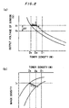
- the toner density (T/D %) of the developer and an output voltage (V) of a magnetic sensor in measuring the permeability of the developer by the magnetic sensor are in the relation represented by a solid line in a graph of Fig. 7 (a) (referred to as T/D-V characteristics hereinafter).
- T/D-V characteristics hereinafter.
- the permeability of the developer is measured by the sensor and the toner density is estimated from a curve of the T/D-V characteristics to control the supply of toner. That is, in this image forming apparatus, operations are programmed so as to judge that the toner density of the developer is below a predetermined value when the output voltage of the sensor exceeds a threshold value V T at which the supply of toner is started to automatically supply toner.
- the above threshold value V T corresponds to the output voltage of the sensor in a case where the toner density of a developer in the stable time period is D b , as shown in Fig. 7 (a).
- the developer having a toner density of D b in the stable time period is used, it is found that an image having an image density I T is obtained from the relation between the toner density (T/D %) of the developer and the image density (ID) of an image transferred to a paper sheet (referred to as T/D-ID characteristics hereinafter) which is represented by a solid line in a graph of Fig. 7 (b).
- the output voltage of the sensor is slightly higher or lower than that in the developer in the stable time period, so that some shift may occur between the toner density analogized from the T/D-V characteristic curve and the actual toner density.
- the output voltage of the sensor is lower than that in a developer in the stable time period,and the T/D-V characteristic curve is shifted on a lower voltage side from the T/D-V characteristic curve in the developer in the stable time period (represented by the solid line in Fig. 7 (a)), as represented by a two-dot and dash line in Fig. 7 (a)
- the above described defects such as lack of image density, fogging, scattering of toner and decrease in resolution are liable to occur.
- the actual toner density of the developer in which the output voltage of the sensor reaches the threshold value V T is decreased to D c which is lower than the toner density D b in the developer in the stable time period because there is some shift between the T/D-V characteristic curve (represented by the two-dot and dash line) in the start developer and the T/D-V characteristic curve (represented by the solid line) in the developer in the stable time period.
- a curve of T/D-ID characteristics is also shifted to the side of a lower image density (on the lower side in Fig. 7 (b)) from the T/D-ID characteristic curve (represented by the solid line in Fig. 7 (b)) in the developer in the stable time period, as represented by a two-dot and dash line in Fig. 7 (b).
- the toner density of the start developer has been conventionally set to a higher value D a such that an image having a predetermined image density (I T as described above) can be obtained at the time of starting the use of the developer, as represented by the two-dot and dash lines in Figs. 7 (a) and 7(b). Consequently, excessive toner exists in the developer in the early stage of image formation, as compared with the developer having a toner density of D b at which an image having the same image density I T can be obtained in the stable time period. Consequently, fogging, scattering of toner and the like occur and the resolution is decreased due to the excessive toner.
- the output voltage of the sensor and the toner density are shifted, as represented by a zigzag line in Fig. 7 (a).
- the toner density and the image density are shifted, as represented by a zigzag line in Fig. 7 (b), to gradually increase the image density.
- image formation must be repeated approximately 3000 times as described above to a time period during which the T/D-V characteristic curve in the developer coincides with the T/D-V characteristic curve in the developer in the stable time period which is represented by the solid line and the T/D-ID characteristic curve in the developer coincides with the T/D-ID characteristic curve in the developer in the stable time period, that is, the stable time period. Accordingly, during that repetition, the defects such as lack of image density shown in Fig. 8 and fogging continuously occur.
- the threshold values V T have always been set to a constant value irrespective of the above described variation in characteristics between the sensors. Therefore, even if the developers having the same properties are used for a plurality of image forming apparatus, the actual toner density of the developer in which the output voltage of the sensor reaches the threshold value V T is shifted for each image forming apparatus. As a result, the image density varies and the degree of occurence of defects such as fogging varies for each image forming apparatus.
- the publication EP-A-O 140 996 relates to a toner dispensing control in a xerographic printer wherein a toner dispenser is controlled in response to a set magnetic density value that is variable during the running-in period of a fresh toner mixture, thereby to take account of the changing packing density of the mixture during the period.
- the replenishment of toner is carried out only dependent on the elapsed operation time of the developer as a function of the time of use. This time of use is counted by the number of prints or the number of exposures, and toner is gradually replenished in a linear manner when time passes by.
- EP-A-O 029 584 discloses a method for operating an electrophotographic copying apparatus using a developer containing toner and carrier to produce a visible toner image.
- the development unit is raced until the amount of charge on the toner in the developer reaches a predetermined level. Only when this predetermined level has been reached, a usual electrophotographic copying procedure commences. Thereby it is intended to avoid a reduction in density of developed images during the initial operation of the apparatus.
- the method according to EP-A-0 029 584 relies on an extended mixing and agitating period of the developer which is continued until the amount of charge on the toner in the developer has been raised to a predetermined level. No explanation is given as to when and under which conditions fresh toner is supplied to the developer in order to take into account that toner is consumed by the image forming procedure.
- the object underlying the present invention is to provide a method for controlling the toner density of a start developer in an image forming apparatus by means of which a good quality of images is achieved through the complete operation period from an early stage onwards.
- the problem is solved by a method for controlling the toner density of a start developer in an image forming apparatus, wherein the start developer comprises a mixture of toner and carrier in a predetermined ratio so that a predetermined image density is obtained, wherein the permeability of the start developer is measured by means of a sensor to provide an output voltage while agitating and mixing the start developer until the output value of the output voltage of the sensor is in the range of 0.9 times or more the output value of the sensor in a developer having the same toner density in a time period during which image characteristics are stabilised after repeated image formation by the image forming apparatus, wherein the same sensor in the image forming apparatus, measuring the permeability of the start developer before image formation, produces an output value V S , wherein a time period elapsed until image characteristics are stabilised after repeated image formation by the image forming apparatus is divided into a plurality of time intervals, that is, a first time interval to a Z-th time interval on the basis of the number of times
- V Tn V S + ⁇ V n to set a threshold value V Tn at which the supply of toner is started for each time interval, and images are formed a predetermined number of times for each time interval on the basis of the threshold value V Tn , wherein, while images are subsequently formed, the permeability V X of the developer is measured by the sensor in the image forming apparatus, thereby to maintain the toner density of the developer at the time of image formation within a predetermined range, such that V X is kept at a level which is less than the threshold value V Tn .
- the problem is solved in a satisfying manner.
- there are no defects such as lack of image density, fogging, scattering of toner and decrease in resolution which occur when the output voltage of the sensor largely falls below that in the developer in the stable time period. Consequently, the use of the method according to the present invention makes it possible always to form good images from an early stage of image formation to a stable time period. Also, a stable control can always be carried out irrespective of any variation in characteristics between sensors in image forming apparatus.
- an output voltage of a sensor is limited to not less than 0,9 times an output voltage of the sensor in a developer having the same toner density in a stable time period and less than a threshold value at which the supply of toner is started.
- the output voltage of the sensor is not less than 0,9 times and less than the output voltage of the sensor in the developer having the same toner density in the stable time period, the T/D-V characteristics in the start developer are below the T/D-V characteristics in the developer in the stable time period, but the difference therebetween is small. Accordingly, an output value of the sensor does not largely vary from the early stage of image formation to the stable time period, so that the sensor can always detect or grasp the precise toner density.
- the output voltage of the sensor is one time, that is, is equal to the output voltage of the sensor in the developer having the same toner density in the stable time period, the output value of the sensor does not vary from the early stage of image formation to the stable time period, so that the sensor can always detect or grasp the precise toner density.
- the output voltage of the sensor reaches a threshold value V T in the stage in which the toner density of the developer is decreased to a toner density D2 higher than a toner density D 3 of the developer in the stable time period. Therefore, toner is supplied before the image density is significantly decreased, as indicated by an arrow represented by a one dot and dash line in Fig. 2 (b). Accordingly, the image density is prevented from being extremely decreased, thereby making it possible to obtain images which practically present no problem.
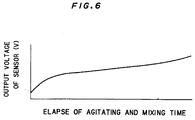
- the output value of the sensor in the start developer tends to be gradually increased with an elapse of agitating and mixing time required to produce the start developer, as shown in Fig. 6. Consequently, in order to adjust the output value of the sensor in the start developer to be in the above described range, the toner and the carrier may be agitated and mixed while measuring the permeability of the developer by the same sensor as that used in a developing device.
- the output value of the sensor in the start developer is one time or more in the above described range in consideration of the decrease in image density in the early stage of image formation.
- the output value is one time or less at which the toner and the carrier can be agitated and mixed in a shorter time period in consideration of the productivity.
- the present invention is applicable to a start developer which is a combination of various types of toner and carriers conventionally known.
- Examples of a toner include a color particle having a particle diameter of approximately 10 ⁇ m produced by mixing additives such as a coloring agent, a charge controlling agent and a parting agent (off-set preventing agent) with a binder resin.
- a binder resin examples include styrene resins (homopolymers or copolymers containing styrene or a styrene substitution product) such as polystyrene, chloropolystyrene, poly- ⁇ -methylstyrene, a styrene-chlorostyrene copolymer, a styrene-propylene copolymer, a styrene-butadiene copolymer, a styrene-vinyl chloride copolymer, a styrene-vinyl acetate copolymer, a styrene-maleic acid copolymer, a styrene-acrylic ester copolymer (styrene-methyl acrylate copolymer, a styrene-ethyl acrylate copolymer, a styrene-butyl
- polyvinyl chloride low molecular-weight polyethylene, low-molecular weight polypropylene, an ethylene-ethyl acrylate copolymer, polyvinyl butyral, ethylene-vinyl acetate copolymer, rosin denatured maleic acid resin, phenol resin, epoxy resin, polyester resin, ionomer resin, polyurethane resin, silicone resin, ketone resin, xylene resin, polyamide resin and the like are included. They are used independently or in combinations. Among them, styrene resins, particularly a styrene-(meta-) acrylic ester copolymer is preferable.
- Examples of a coloring agent include various coloring pigments, an extender pigment, a conductive pigment, a magnetic pigment, a photoconductive pigment and the like. They are used independently or in combinations according to the usage.
- Carbon black such as furnace black, channel black, thermal, gas black, oil black, acetylene black and the like; Lamp-black; Aniline black
- Zinc white Titanium oxide, Antimony white, Zinc sulfide
- Red ion oxide Cadmium red, Red lead, Mercury cadmium sulfide, Permanent red 4R, Lithol red, Pyrazolone red, Watching red calcium salt, Lake red D, Brilliant carmine 6B, Eosine lake, Rhodamine lake B, Alizarine lake, Brilliant carmine 3B
- expender pigment examples include Baryte powder, barium carbonate, clay, silica, white carbon, talc, alumina white and the like.
- Examples of a conductive pigment include conductive carbon black, aluminum powder and the like.
- Examples of a magnetic pigment include: triiron tetroxide (Fe 3 O 4 ), iron sesquioxide ( ⁇ -Fe 2 O 3 ), zinc iron oxide (ZnFe 2 O 4 ), yttrium iron oxide (Y 3 Fe 5 O 12 ), cadmium iron oxide (CdFe 2 O 4 ), gadolinium iron oxide (Gd 3 Fe 5 O 4 ), copper iron oxide (CuFe 2 O 4 ), lead iron oxide (PbFe 12 O 19 ), neodymium iron oxide (NdFeO 3 ), barium iron oxide (BaFe 12 O 19 ), magnesium iron oxide (MgFe 2 O 4 ), manganese iron oxide (MnFe 2 O 4 ), lanthanum iron oxide (LaFeO 3 ), iron powder, cobalt powder, nickel powder and the like.
- Triiron tetroxide Fe 3 O 4
- iron sesquioxide ⁇ -Fe 2 O 3
- zinc iron oxide ZnFe 2 O 4
- Examples of a photoconductive pigment include zinc oxide, selenium, cadmium sulfide, cadmium selenide and the like.
- the amount of the coloring agent is 1 to 20 parts by weight and preferably 3 to 15 parts by weight per 100 parts by weight of a binder resin.
- charge controlling agent two types of charge controlling agents, that is, one for controlling positive charges and one for controlling negative charges are used depending on the polarity of toner.
- Examples of a charge controlling agent for controlling positive charges include organic compounds having a basic nitrogen atom, for example, basic dyes, aminopyrin, a pyrimidine compound, polycyclic polyamino compound, aminosilane and the like and fillers subjected to surface treatment using the above compounds.
- Examples of a charge controlling agent for controlling negative charges include compounds containing a carboxyl group (for example, alkyl salicylic acid metal chelate and the like), metal complex dyes, fatty acid soap, metallic naphthenate and the like.
- a carboxyl group for example, alkyl salicylic acid metal chelate and the like
- metal complex dyes for example, fatty acid soap, metallic naphthenate and the like.
- the amount of the charge controlling agent is 0,1 to 10 parts by weight and preferably 0,5 to 8 parts by weight per 100 parts by weight of a binder resin.
- a parting agent examples include aliphatic hydrocarbon, aliphatic metallic salt, higher fatty acid, aliphatic ester or its partial sponification matter, silicone oil, various waxes and the like.
- aliphatic hydrocarbon having a weight average molecular weight of approximately 1000 to 10000 is preferable. More specifically, the use of one or combinations of low molecular-weight polypropylene, low molecular-weight polyethylene, paraffin wax and a low molecular-weight olefin polymer comprising an olefin unit containing four or more carbon atoms is suitable.
- the amount of the parting agent is 0,1 to 10 parts by weight and preferably 0,5 to 8 parts by weight per 100 parts by weight of a binder resin.
- the toner is produced by melting and kneading a mixture obtained by previously kneading the foregoing components to be uniform using a dry-blender, a Henschel mixer, a ball mill or the like to be uniform using a kneader such as a Banbury mixer, a roll, a single or twin axle extruding kneader and then, cooling and grinding a mixture obtained by kneading, and classifying the mixture as required.
- a dry-blender a Henschel mixer, a ball mill or the like
- a kneader such as a Banbury mixer, a roll, a single or twin axle extruding kneader and then, cooling and grinding a mixture obtained by kneading, and classifying the mixture as required.
- the particle diameter of the toner is 3 to 35 ⁇ m and preferably 5 to 25 ⁇ m.
- Examples of a carrier include particles of iron, oxidation treating iron, reducing iron, magnetite, copper, silicon steel, ferrite, nickel, cobalt and the like, particles of alloys of the materials and manganese, zinc, aluminum and the like, particles of an iron-nickel alloy, an iron-cobalt alloy and the like, particles obtained by dispersing the above various particles in a binder resin, particles of ceramics such as titanium oxide, aluminum oxide, copper oxide, magnesium oxide, lead oxide, zirconium oxide, silicon carbide, magnesium titanate, barium titanate, lithium titanate, lead titanate, lead zirconate and lithium niobate, particles of materials having a high dielectric constant such as ammonium dihydrogenphosphate (NH 4 H 2 PO 4 ), potassium dihydrogenphosphate (KH 2 PO 4 ) and Rochelle salt.
- iron powder of oxidation treating iron, reducing oxide and the like and ferrite powder are preferable because they are superior in image characteristics and low in cost.
- a resin coating layer can also be formed on the surface of the above described carrier for the purpose of, for example, controlling the amount of charge of toner and the polarity thereof, improving dependence on humidity and preventing film formation.
- Examples of a polymer used for the resin coating layer include a (meta-)acrylic polymer, a styrene polymer, a styrene-(meta-)acrylic copolymer, an olefin polymer (polyethylene, chlorinated polyethylene, polypropylene and the like), polyvinyl chloride, polycarbonate, polyester resin, unsaturated polyester resin, polyamide resin, polyurethane resin, epoxy resin, silicone resin, fluorine resin (polytetrafluoroethylene, polychlorotrifluoroetylene, polyvinylidene fluoride and the like), phenol resin, xylene resin, diallyl phthalate resin and the like.
- a (meta-)acrylic polymer polymer, a styrene polymer, a styrene-(meta-)acrylic copolymer
- an olefin polymer polyethylene, chlorinated polyethylene, polypropylene and the
- a (meta-) acrylic polymer a styrene polymer, styrene-(meta-) acrylic copolymer, silicone resin or fluorine resin is preferable in terms of frictional electrification of toner and mechanical strength.
- the above described polymers can be also used independently or in combinations.
- a coating method for forming the resin coating layer made of the above described polymer on the surface of the carrier known methods such as a fluidized bed method and a rolling method can all be employed.
- the particle diameter of the carrier is 30 to 200 ⁇ m and preferably 50 to 130 ⁇ m.
- the mixing ratio of the toner to the carrier may be the same as the conventional one. Furthermore, in order to improve the fluidity of the start developer, a fluidizing agent such as colloidal silica can be further mixed with the above toner and the above carrier.
- a mixing equipment used for agitating and mixing toner and a carrier a nauter mixer, a ball mill, a V-type mixing machine and the like are exemplified.
- a sensor provided in the above developing portion measures the permeability of the start developer, so that an output voltage V S of the sensor is read in a processing unit of the image forming apparatus (step S1).
- a correction voltage ⁇ V stored in a memory is read in the processing unit (step S2).
- an arithmetic operation is executed on the basis of the following equation (I) to set a threshold value V T at which the supply of toner is started, and this threshold value V T is stored in the memory (step S3):
- V T V S + ⁇ V
- ⁇ V (V T ' - V S ')
- step S5 when image formation was started in the step S4, the permeability of the developer is measured by the sensor, so that an output voltage V X of the sensor is read (step S5).
- the read output voltage V X is compared with the previously described threshold value V T (step S6).
- V X ⁇ V T that is, the output voltage V X of the sensor does not exceed the threshold value V T
- the program proceeds to the step S8 without passing through the step S7.
- V X > V T that is, the output voltage V X of the sensor exceeds the threshold value V T
- the program proceeds to the step S7.
- predetermined amounts of toner are supplied and then, the program proceeds to the step S8.
- step S8 it is judged whether or not a signal for terminating this program is input to a control portion of the image forming apparatus.
- the signal for terminating the program is input by an operator when a trouble occurs in the developer currently used or the developer in the developing portion is replaced with a new start developer by, for example, repairing or checking the image forming apparatus.
- step S8 When it is judged in the step S8 that the signal for terminating the program is input, the program proceeds to the step S9. In the step S9, a series of program is terminated. When this image forming apparatus is driven again using the new start developer, the program described in the foregoing is repeated again from the step S1
- step S8 when it is judged in the step S8 that the signal for terminating the program is not input, a loop returning to the step S5 from the step S8 is made. In a time period elapsed until the signal for terminating the program is input, the operations in the steps S5 to S8 are repeated on the basis of data on the threshold value V T which is stored in the memory.
- the output voltage V X is gradually raised from V S which is its initial value to the threshold value V T along a T/D-V characteristic curve represented by a one dot and dash line in Fig. 2 (a). During this time, the output voltage V X of the sensor does not exceed the threshold value V T . Accordingly, the program proceeds in a path which does not pass through the step S7 for supplying toner. Consequently, toner is not supplied until the toner density is decreased to D 2 .
- the threshold value V T at which the supply of toner is started is set on the basis of the foregoing equation (I) for each image forming apparatus. Accordingly, a stable control can always be carried out irrespective of the variation in characteristics between sensors in image forming apparatuses.
- the start developer according to the present invention eliminates the possibility of causing defects such as lack of image density, fogging, scattering of toner and decrease in resolution. Accordingly, good images can always be formed irrespective of the variation in characteristics between sensors in image forming apparatus and from an early stage of image formation to a stable time period.
- a second manner of the method of controlling the toner density according to the present invention is employed in which a time period from the early stage of image formation to the stable time period is divided into a plurality of time periods and control is carried out for each time period.
- the second manner of the control method according to the present invention will be described while referring to flow charts of Figs. 3 and 4 and Fig. 5.
- the drawings show a case where a time period from an early stage of image formation to a stable time period is divided into five time periods, that is, the first time period to the fifth time period and control is carried out for each time period. Assuming that the total number of times of image formation from the early stage of image formation to the stable time period is 3000, the number of times thereof for each time period is 600 obtained by cutting 3000 into five equal divisions.
- step S1 When a start developer having a toner density of D 1 according to the present invention is injected into a developing portion of an image forming apparatus to start the image forming apparatus, n in a memory for setting any one of the time periods is first reset (step S1).
- a sensor provided in the above developing portion measures the permeability of the start developer, so that an output voltage V S of the sensor is read in a processing unit of the image forming apparatus (step S2).
- the permeability of the developer is then measured by the sensor, so that an output voltage V X of the sensor is read (step S6).
- the read output voltage V X is compared with the previously described threshold value V T1 (step S7).
- V X ⁇ V T1 that is, the output voltage V X of the sensor does not exceed the threshold value V T1
- the program proceeds to the step $9 without passing through the step S8.
- V X > V T1 that is, the output voltage V X of the sensor exceeds the threshold value V T1
- the program proceeds to the step S8.
- a predetermined amount of toner is supplied and then, the program proceeds to the step S9.
- step S11 it is judged whether or not the above described signal for terminating the program is input to a control portion of the image forming apparatus by an operator.
- step S9 When it is judged in the step S9 that the number of times of image formation in the first time period reaches a predetermined number of times, the program proceeds to the step S10. In the step S10, it is judged whether or not image formation in the first to fifth time periods is terminated.
- Image formation is made currently in the first time period. Accordingly, it is reasonably judged in the step S10 that image formation in the first to fifth time periods is not terminated. Consequently, the program returns to the step S3. In the step S3, 1 is added to n in the above memory, so that image formation in the second time period is started through the same procedure as described above.
- ⁇ V n n (V T ' - V S ')/5 (where n in the foregoing equation represents an integer between 2 and 5).
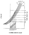
- the correction voltages ⁇ V n found by the foregoing equation (IV) are values so set that the differences between the output voltage V S in the start developer and threshold values V T1 to V T5 in the respective time periods are equal to each other, as shown in Fig. 5.
- step S10 When the number of times of image formation in the fifth time period reaches a predetermined number of times so that the program proceeds from the step S9 to the step S10, it is judged in the step S10 that image formation in the first to fifth time periods is terminated. Consequently, the program proceeds to the step S11. A loop from the step S6 to the step S11 through a path represented by a broken line is made. In a time period elapsed until the signal for terminating the program is input , the operations are repeated on the basis of data on the threshold value V T5 which is finally stored in the memory.
- the output voltage V X is gradually raised from V S which is its initial value to the first threshold value V T1 along a T/D-V characteristic curve C 1 shown in Fig. 5.
- the output voltage V X of the sensor does not exceed the threshold value V T1 . Accordingly, the program proceeds in a path which does not pass through the step S8 for supplying toner. Consequently, toner is not supplied until the toner density is decreased to D 2 .
- a new threshold value V T2 is set, so that image formation in the second time period is started. Thereafter, image formation in the second to fifth time periods is repeated with the same procedure as described above on the basis of T/D-V characteristic curves C 2 to C 6 and threshold values V T2 to V T5 . Simultaneously with the termination of image formation in the fifth time period, the T/D-V characteristic curve in the developer coincides with the T/D-V characteristic curve C 6 in the developer in the stable time period, leading to the stable time period.
- a time period from the early stage of image formation to the stable time period is divided into a plurality of time periods on the basis of the number of times of image formation, and a threshold value V Tn is set for each time period. Accordingly, a finer control can be carried out. More specifically, toner can be supplied earlier, as compared with the control method shown in Fig. 1, thereby making it possible to prevent any decrease in image density more reliably.
- the time period from the early stage of image formation to the stable time period is divided into five time periods, that is, the first time period to the fifth time period
- the time period may also be divided into a plurality of time periods, that is, four or less time periods or six or more time periods.
- a toner and a carrier having the following composition are mixed in a weight ratio of 3,5 to 96,5 and are agitated and mixed using a nauter mixer (trade name NX-S, product of Hosokawa Mikuron Co., Ltd.), to produce a start developer having a sensor output magnification of M V shown in Table 1, where M V is an output voltage V S in a start developer divided by an output voltage in a developer having the same toner density in the stable time period.
- a nauter mixer trade name NX-S, product of Hosokawa Mikuron Co., Ltd.
- Toner having a central particle diameter of 10 ⁇ m
- styrene-acrylic copolymer 100 parts by weight carbon black 8,5 parts by weight monoazo dye 2 parts by weight low molecular-weight polypropylene 3 parts by weight
- Carrier having a central particle diameter of 100 ⁇ m
- Continuous copying of a solid-black document is made using the above described start developer for an electrophotographic copying machine (DC-5585, product of Mita Industrial Co., Ltd.) and using the same toner as that used in the above described embodiments and comparative example as toner for supply in accordance with the flow chart of Fig. 1.
- the densities of copy images in the early stage of copy (on the first to 10-th paper sheets), a copy image on the 100-th paper sheet and a copy image on the 100000-th paper sheet are measured using a reflection densitometer (trade name TC-6D, product of Tokyo Densyoku Co., Ltd.).
- the margin portion of the copy image on the 100000-th paper sheet used in the above described measurement of resolution and the interior of the electrophotographic copying machine after making 100000 copies are observed, to evaluate as ⁇ a case where scattering of toner is hardly observed in both the margin portion of the copy image and the interior of the electrophotographic copying machine and as ⁇ a case where scattering of toner is observed in at least one of the margin portion of the copy image and the interior of the electrophotographic copying machine.
- the densities of images are always stable and there occurs no fogging and scattering of toner, so that the resolution is high. Consequently, it becomes clear that the use of the start developer having a sensor output magnification of 0,9 or more according to the present invention allows stable images always to be formed from the early stage of image formation to the stable time period.
Landscapes
- Physics & Mathematics (AREA)
- General Physics & Mathematics (AREA)
- Dry Development In Electrophotography (AREA)
- Control Or Security For Electrophotography (AREA)
Description
- The present invention relates to a two-component start developer having a toner and a carrier mixed witn each other in a predetermined ratio which is used for an image forming apparatus utilizing a so-called electrophotographic method such as an electrostatic copying machine or a laser beam printer and a method of controlling the toner density in forming images using such a start developer.
- In an electrophotographic method, a photoreceptor is first exposed to form an electrostatic latent image on its surface. A developer containing toner is then brought into contact with this electrostatic latent image, to develop this electrostatic latent image into a toner image. This toner image is transferred to the surface of paper sheets from the surface of the photoreceptor,and is fixed to the surface of the paper sheets by, for example, applying pressure and heat.
- As a developer used in the above described electrophotographic method, a two-component developer containing toner and a carrier are generally used. The carrier is made of a magnetic material such as ferrite powder and circulates in a developing device for developing an electrostatic latent image into a toner image with the toner being electrostatically adsorbed thereon.
- A developer first used in newly manufacturing an image forming apparatus utilizing the above described electrophotographic method or after maintenance such as a repair and a check of the image forming apparatus, is of the type having a toner and a carrier mixed with each other in a predetermined ratio according to the conditions such as a the image densities of images, which is referred to as a start developer.
- In the start developer, the image density of an image in the early stage of image formation and the amount of charge based on, for example, the presence or absence of an occurrence of scattering of toner at the time of image formation are defined in addition to the above described mixing ratio of the toner to the carrier.
- However, there have been conventionally problems irrespective of the above described definition that the image formed is fogged, the toner is scattered in the image formed and the image forming apparatus, and the resolution of the image formed is decreased in addition to the problem that the image density is significantly lowered as shown in Fig. 8 from the early stage of image formation to a time period during which image characteristics are stabilized (referred to as "stable time period" hereinafter) after repeating image formation approximately 3000 times.
- Furthermore, when the same type of start developers are used for a plurality of image forming apparatus, there is a problem that the degree of occurrence of defects such as fogging varies in addition to the problem that the image density varies for each image forming apparatus as image formation is repeated.
- The inventors of the present application have found the following cause and effect relation between the start developer and inferior images as a result of examining the causes of occurrence of various defects from the early stage of image formation to the stable time period from various viewpoints.
- More specifically, the toner density (T/D %) of the developer and an output voltage (V) of a magnetic sensor in measuring the permeability of the developer by the magnetic sensor are in the relation represented by a solid line in a graph of Fig. 7 (a) (referred to as T/D-V characteristics hereinafter). In a conventional image forming apparatus, therefore, the permeability of the developer is measured by the sensor and the toner density is estimated from a curve of the T/D-V characteristics to control the supply of toner. That is, in this image forming apparatus, operations are programmed so as to judge that the toner density of the developer is below a predetermined value when the output voltage of the sensor exceeds a threshold value VT at which the supply of toner is started to automatically supply toner.
- Meanwhile, the above threshold value VT corresponds to the output voltage of the sensor in a case where the toner density of a developer in the stable time period is Db, as shown in Fig. 7 (a). When the developer having a toner density of Db in the stable time period is used, it is found that an image having an image density IT is obtained from the relation between the toner density (T/D %) of the developer and the image density (ID) of an image transferred to a paper sheet (referred to as T/D-ID characteristics hereinafter) which is represented by a solid line in a graph of Fig. 7 (b).
- In a conventional start developer, however, the output voltage of the sensor is slightly higher or lower than that in the developer in the stable time period, so that some shift may occur between the toner density analogized from the T/D-V characteristic curve and the actual toner density. Particularly when a start developer is used in which the output voltage of the sensor is lower than that in a developer in the stable time period,and the T/D-V characteristic curve is shifted on a lower voltage side from the T/D-V characteristic curve in the developer in the stable time period (represented by the solid line in Fig. 7 (a)), as represented by a two-dot and dash line in Fig. 7 (a), the above described defects such as lack of image density, fogging, scattering of toner and decrease in resolution are liable to occur.
- The foregoing will be described in more detail.
- More specifically, consider a case where the start developer in which the T/D-V characteristic curve is shifted on the lower voltage side from the T/D-V characteristic curve in the developer in the stable time period is used as described above. In this case, if toner is consumed, the toner density of the developer is gradually decreased from Da which is its initial value and correspondingly, the output voltage of the sensor is gradually increased from VS which is its initial value along the T/D-V characteristic curve represented by the two-dot and dash line. When image formation is repeated approximately 100 times, the output voltage of the sensor reaches the above described threshold value VT at which the supply of toner is started.
- However, the actual toner density of the developer in which the output voltage of the sensor reaches the threshold value VT is decreased to Dc which is lower than the toner density Db in the developer in the stable time period because there is some shift between the T/D-V characteristic curve (represented by the two-dot and dash line) in the start developer and the T/D-V characteristic curve (represented by the solid line) in the developer in the stable time period.
- Moreover, in this start developer, a curve of T/D-ID characteristics is also shifted to the side of a lower image density (on the lower side in Fig. 7 (b)) from the T/D-ID characteristic curve (represented by the solid line in Fig. 7 (b)) in the developer in the stable time period, as represented by a two-dot and dash line in Fig. 7 (b).
- Consequently, the image density significantly drops, as indicated by an arrow represented by a two-dot and dash line in Fig. 7 (b), resulting in lack of image density.
- Furthermore, the toner density of the start developer has been conventionally set to a higher value Da such that an image having a predetermined image density (IT as described above) can be obtained at the time of starting the use of the developer, as represented by the two-dot and dash lines in Figs. 7 (a) and 7(b). Consequently, excessive toner exists in the developer in the early stage of image formation, as compared with the developer having a toner density of Db at which an image having the same image density IT can be obtained in the stable time period. Consequently, fogging, scattering of toner and the like occur and the resolution is decreased due to the excessive toner.
- When the output voltage of the sensor reaches the above described threshold value VT, the following pattern is repeated. More specifically, toner is supplied when the output voltage slightly exceeds the threshold value VT. When the toner has been supplied, image formation is repeated. Consequently, the output voltage slightly exceeds the threshold value VT, so that toner is supplied again. In addition, when image formation is repeated as described above, the T/D-V characteristics in the developer gradually approach the solid line from the two-dot and dash line, in Fig. 7 (a).
- In this stage, therefore, the output voltage of the sensor and the toner density are shifted, as represented by a zigzag line in Fig. 7 (a). Correspondingly, the toner density and the image density are shifted, as represented by a zigzag line in Fig. 7 (b), to gradually increase the image density. However, image formation must be repeated approximately 3000 times as described above to a time period during which the T/D-V characteristic curve in the developer coincides with the T/D-V characteristic curve in the developer in the stable time period which is represented by the solid line and the T/D-ID characteristic curve in the developer coincides with the T/D-ID characteristic curve in the developer in the stable time period, that is, the stable time period. Accordingly, during that repetition, the defects such as lack of image density shown in Fig. 8 and fogging continuously occur.
- Furthermore, in the shift stage represented by the zigzag lines, a phenomenon occurs that the output voltage of the sensor is not changed irrespective of the gradual increase in the actual toner density. Accordingly, the supply of toner becomes excessive. As a result, occurrence of the defects such as fogging is promoted.
- The reason why the image density varies and the degree of occurrence of defects such as fogging varies when the same type of developers are used for a plurality of image forming apparatuses is that there is a variation in characteristics between sensors therein.
- More specifically, if there is a variation in characteristics between the sensors, there arises a difference between output voltages of the sensors when developers having the same permeability are measured. Consequently, the above described T/D-V characteristic curve is shifted up and down for each sensor and for each image forming apparatus, as shown in Fig. 9.
- In the conventional image forming apparatus, however, the threshold values VT have always been set to a constant value irrespective of the above described variation in characteristics between the sensors. Therefore, even if the developers having the same properties are used for a plurality of image forming apparatus, the actual toner density of the developer in which the output voltage of the sensor reaches the threshold value VT is shifted for each image forming apparatus. As a result, the image density varies and the degree of occurence of defects such as fogging varies for each image forming apparatus.
- The publication EP-A-O 140 996 relates to a toner dispensing control in a xerographic printer wherein a toner dispenser is controlled in response to a set magnetic density value that is variable during the running-in period of a fresh toner mixture, thereby to take account of the changing packing density of the mixture during the period. The replenishment of toner is carried out only dependent on the elapsed operation time of the developer as a function of the time of use. This time of use is counted by the number of prints or the number of exposures, and toner is gradually replenished in a linear manner when time passes by.
- In the toner dispensing control according to EP-A-0 140 996 the actual consumption of toner is not taken into account, which actual consumption of toner greatly depends on the kind of images formed in the image forming apparatus, wherein the consumption is considerably higher when the originals comprise, for example, very much text and/or dark pictures compared with a situation where the originals are very bright and contain little text. In that conventional toner dispensing control no correlation is made between a start phase and a stabilized stage of operation which is usually achived when 3000 images or so have been produces.
- The publication EP-A-O 029 584 discloses a method for operating an electrophotographic copying apparatus using a developer containing toner and carrier to produce a visible toner image. In that conventional operation method, the development unit is raced until the amount of charge on the toner in the developer reaches a predetermined level. Only when this predetermined level has been reached, a usual electrophotographic copying procedure commences. Thereby it is intended to avoid a reduction in density of developed images during the initial operation of the apparatus. Hence, the method according to EP-A-0 029 584 relies on an extended mixing and agitating period of the developer which is continued until the amount of charge on the toner in the developer has been raised to a predetermined level. No explanation is given as to when and under which conditions fresh toner is supplied to the developer in order to take into account that toner is consumed by the image forming procedure.
- The object underlying the present invention is to provide a method for controlling the toner density of a start developer in an image forming apparatus by means of which a good quality of images is achieved through the complete operation period from an early stage onwards.
- According to a first aspect of the invention, the problem is solved by a method for controlling the toner density of a start developer in an image forming apparatus, wherein the start developer comprises a mixture of toner and carrier in a predetermined ratio so that a predetermined image density is obtained, wherein the permeability of the start developer is measured by means of a sensor to provide an output voltage while agitating and mixing the start developer until the output value of the output voltage of the sensor is in the range of 0.9 times or more the output value of the sensor in a developer having the same toner density in a time period during which image characteristics are stabilised after repeated image formation by the image forming apparatus, wherein the same sensor in the image forming apparatus, measuring the permeability of the start developer before image formation, produces an output value VS, wherein a previously set correction value ΔV is added to the output value VS on the basis of the following equation (I):

- According to a further development of the present invention, the correction value ΔV is the difference between a reference value VS, of output voltages and a reference value VT, of threshold values at which the supply of toner is started in the same type of start developers, which is defined in the following equation (II):

- According to a second aspect of the present invention, the problem is solved by a method for controlling the toner density of a start developer in an image forming apparatus, wherein the start developer comprises a mixture of toner and carrier in a predetermined ratio so that a predetermined image density is obtained, wherein the permeability of the start developer is measured by means of a sensor to provide an output voltage while agitating and mixing the start developer until the output value of the output voltage of the sensor is in the range of 0.9 times or more the output value of the sensor in a developer having the same toner density in a time period during which image characteristics are stabilised after repeated image formation by the image forming apparatus, wherein the same sensor in the image forming apparatus, measuring the permeability of the start developer before image formation, produces an output value VS, wherein a time period elapsed until image characteristics are stabilised after repeated image formation by the image forming apparatus is divided into a plurality of time intervals, that is, a first time interval to a Z-th time interval on the basis of the number of times of image formation, wherein a correction value ΔVn (n = 0, 1, 2, 3, ... Z-2, Z-1, Z) which gradually increases for each time interval is added to the output value VS on the basis of the following equation (III):

- According to the invention, the problem is solved in a satisfying manner. Hence, there are no defects such as lack of image density, fogging, scattering of toner and decrease in resolution which occur when the output voltage of the sensor largely falls below that in the developer in the stable time period. Consequently, the use of the method according to the present invention makes it possible always to form good images from an early stage of image formation to a stable time period. Also, a stable control can always be carried out irrespective of any variation in characteristics between sensors in image forming apparatus. When using the method according to the second aspect of the present invention, it is possible to carry out a finer control because the time period from an early stage to a stable time period of an image formation is divided into a plurality of smaller time periods.
- The above object, features, aspects and advantages of the present invention will become more apparent from the following detailed description of the present invention when taken in conjunction with the accompanying drawings.
-
- Fig. 1 is a flow chart showing one example of a method of controlling the toner density according to the present invention;
- Fig. 2 (a) is a graph showing the relation between the toner density and the output voltage of a sensor in controlling the toner density in the above described control method using a start developer according to the present invention;
- Fig. 2 (b) is a graph showing the relation between the toner density and the image density in carrying out the above described control;
- Fig. 3 is a flow chart showing the first half in another example of the method of controlling the toner density according to the present invention;
- Fig. 4 is a flow chart showing the second half in the above described control method;
- Fig. 5 is a graph showing the relation between the toner density and the output voltage of a sensor in carrying out the above described control;
- Fig. 6 is a graph showing the relation between agitating and mixing time required to produce a start developer and an output voltage of a sensor;
- Fig. 7 (a) is a graph showing the relation between the toner density and the output voltage of a sensor in controlling the toner density using a conventional start developer;
- Fig. 7 (b) is a graph showing the relation between the toner density and the image density in carrying out the above described control;
- Fig. 8 is a graph showing the shift of the image density in continuously forming images using the conventional start developer; and
- Fig. 9 is a graph showing the shift of the relation between the toner density and the output voltage of a sensor due to the variation in characteristics between sensors.
- It is for the following reasons that in a start developer according to the present invention, an output voltage of a sensor is limited to not less than 0,9 times an output voltage of the sensor in a developer having the same toner density in a stable time period and less than a threshold value at which the supply of toner is started.
- More specifically, when the above described output voltage of the sensor is less than 0,9 times the output voltage of the sensor in the developer in the stable time period, the difference between T/D-V characteristics in the start developer and T/D-V characteristics in the developer in the stable time period is too great, thereby causing the above described defects such as decrease in image density and fogging.
- Furthermore, when the output of the sensor is not less than the threshold value at which the supply of toner is started, toner is supplied simultaneously with the start of image formation, so that toner in the developer always becomes excessive. Consequently, fogging, scattering of toner and the like occur and the resolution is decreased due to the excessive toner.
- On the other hand, when the output voltage of the sensor is not less than 0,9 times and less than the output voltage of the sensor in the developer having the same toner density in the stable time period, the T/D-V characteristics in the start developer are below the T/D-V characteristics in the developer in the stable time period, but the difference therebetween is small. Accordingly, an output value of the sensor does not largely vary from the early stage of image formation to the stable time period, so that the sensor can always detect or grasp the precise toner density.
- Furthermore, when the output voltage of the sensor is one time, that is, is equal to the output voltage of the sensor in the developer having the same toner density in the stable time period, the output value of the sensor does not vary from the early stage of image formation to the stable time period, so that the sensor can always detect or grasp the precise toner density.
- Consequently, when the output voltage of the sensor is not less than 0,9 times nor more than one time the output voltage of the sensor in the developer having the same toner density in the stable time period, there is no possibility of causing defects such as decrease in image density and fogging.
- Consider a case where the output voltage of the sensor exceeds one time the output voltage of the sensor in the developer having the same toner density in the stable time period and is less than the threshold value at which the supply of toner is started, as represented by a one dot and dash line in Fig. 2 (a). In this case, if toner is consumed, the toner density of the developer is gradually decreased from D1 which is its initial value and correspondingly, the output of the sensor is gradually increased from VS which is its initial value along a T/D-V characteristic curve represented by a one dot and dash line. The output voltage of the sensor reaches a threshold value VT in the stage in which the toner density of the developer is decreased to a toner density D2 higher than a toner density D3 of the developer in the stable time period. Therefore, toner is supplied before the image density is significantly decreased, as indicated by an arrow represented by a one dot and dash line in Fig. 2 (b). Accordingly, the image density is prevented from being extremely decreased, thereby making it possible to obtain images which practically present no problem.
- When the output voltage of the sensor has reached the threshold value VT, the following pattern is repeated. More specifically, toner is supplied when the output voltage slightly exceeds the threshold value VT. When the toner has been supplied, image formation is repeated. Consequently, the output voltage slightly exceeds the threshold value VT, so that toner is supplied again. In addition, when image formation is repeated as described above, the T/D-V characteristics in the developer gradually approaches a solid line from the one dot and dash line, in Fig. 2 (a).
- Consequently, in this stage, the output voltage of the sensor and the toner density are shifted, as represented by a zigzag line in Fig. 2 (a). Correspondingly, the toner density and the image density are shifted, as represented by a zigzag line in Fig. 2 (b), to gradually increase the image density. Consequently, the decrease in image density in the early stage of image formation is early solved.
- Furthermore, in the shift stage represented by the zigzag lines, a phenomenon occurs that the output voltage of the sensor is constant and the actual toner density is gradually decreased. Consequently, a tendency to excessive toner which arises by the supply of toner at the toner density D2 higher than the toner density D3 of the developer in the stable time period is corrected, to prevent fogging, scattering of toner, decrease in resolution and the like due to the excessive toner.
- The output value of the sensor in the start developer tends to be gradually increased with an elapse of agitating and mixing time required to produce the start developer, as shown in Fig. 6. Consequently, in order to adjust the output value of the sensor in the start developer to be in the above described range, the toner and the carrier may be agitated and mixed while measuring the permeability of the developer by the same sensor as that used in a developing device.
- It is preferable that the output value of the sensor in the start developer is one time or more in the above described range in consideration of the decrease in image density in the early stage of image formation. On the other hand, it is preferable that the output value is one time or less at which the toner and the carrier can be agitated and mixed in a shorter time period in consideration of the productivity.
- The present invention is applicable to a start developer which is a combination of various types of toner and carriers conventionally known.
- Examples of a toner include a color particle having a particle diameter of approximately 10 µm produced by mixing additives such as a coloring agent, a charge controlling agent and a parting agent (off-set preventing agent) with a binder resin.
- Examples of a binder resin include styrene resins (homopolymers or copolymers containing styrene or a styrene substitution product) such as polystyrene, chloropolystyrene, poly-α-methylstyrene, a styrene-chlorostyrene copolymer, a styrene-propylene copolymer, a styrene-butadiene copolymer, a styrene-vinyl chloride copolymer, a styrene-vinyl acetate copolymer, a styrene-maleic acid copolymer, a styrene-acrylic ester copolymer (styrene-methyl acrylate copolymer, a styrene-ethyl acrylate copolymer, a styrene-butyl acrylate copolymer, a styrene-octyl acrylate copolymer, a styrene-phenyl acrylate copolymer and the like), a styrene-methacrylate ester copolymer (a styrene-methyl methacrylate copolymer, a styrene-ethyl methacrylate copolymer, a styrene-butyl methacrylate copolymer, a styrene-phenyl methacrylate copolymer and the like), a styrene-α methyl chloroacrylate copolymer, a styrene-acrylonitrile-acrylic ester copolymer. And also polyvinyl chloride, low molecular-weight polyethylene, low-molecular weight polypropylene, an ethylene-ethyl acrylate copolymer, polyvinyl butyral, ethylene-vinyl acetate copolymer, rosin denatured maleic acid resin, phenol resin, epoxy resin, polyester resin, ionomer resin, polyurethane resin, silicone resin, ketone resin, xylene resin, polyamide resin and the like are included. They are used independently or in combinations. Among them, styrene resins, particularly a styrene-(meta-) acrylic ester copolymer is preferable.
- Examples of a coloring agent include various coloring pigments, an extender pigment, a conductive pigment, a magnetic pigment, a photoconductive pigment and the like. They are used independently or in combinations according to the usage.
- The following are suitable examples of the coloring pigments:
- Carbon black such as furnace black, channel black, thermal, gas black, oil black, acetylene black and the like; Lamp-black; Aniline black
- Zinc white, Titanium oxide, Antimony white, Zinc sulfide
- Red ion oxide, Cadmium red, Red lead, Mercury cadmium sulfide, Permanent red 4R, Lithol red, Pyrazolone red, Watching red calcium salt, Lake red D, Brilliant carmine 6B, Eosine lake, Rhodamine lake B, Alizarine lake, Brilliant carmine 3B
- Chrome orange, Molybdenum orange, Permanent orange GTR, Pyrazolone orange, Vulcan orange, Indanthrene brilliant orange RK, Benzidine orange G, Indanthrene brilliant orange GK
- Chrome yellow, Zinc yellow, Cadmium yellow, Yellow iron oxide, Mineral fast yellow, Nickel titanium yellow, Naples yellow, Naphthol yellow S, Hansa yellow G, Hansa yellow 10G, Benzidine yellow G, Benzidine yellow GR, Quinoline yellow lake, Permanent yellow NCG, Tartrazine lake
- Chrome green, Chromium oxide, Pigment green B, Malachite green lake, Fanal yellow green G
- Prussian blue, Cobalt blue, Alkali blue lake, Victoria blue lake, Partially chlorinated phthalocyanine blue, Fast sky blue, Indanthrene blue BC
- Manganese violet, Fast violet B, Methyl violet lake
- Examples of an expender pigment include Baryte powder, barium carbonate, clay, silica, white carbon, talc, alumina white and the like.
- Examples of a conductive pigment include conductive carbon black, aluminum powder and the like.
- Examples of a magnetic pigment include: triiron tetroxide (Fe3O4), iron sesquioxide (γ-Fe2O3), zinc iron oxide (ZnFe2O4), yttrium iron oxide (Y3Fe5O12), cadmium iron oxide (CdFe2O4), gadolinium iron oxide (Gd3Fe5O4), copper iron oxide (CuFe2O4), lead iron oxide (PbFe12O19), neodymium iron oxide (NdFeO3), barium iron oxide (BaFe12O19), magnesium iron oxide (MgFe2O4), manganese iron oxide (MnFe2O4), lanthanum iron oxide (LaFeO3), iron powder, cobalt powder, nickel powder and the like.
- Examples of a photoconductive pigment include zinc oxide, selenium, cadmium sulfide, cadmium selenide and the like.
- The amount of the coloring agent is 1 to 20 parts by weight and preferably 3 to 15 parts by weight per 100 parts by weight of a binder resin.
- As a charge controlling agent, two types of charge controlling agents, that is, one for controlling positive charges and one for controlling negative charges are used depending on the polarity of toner.
- Examples of a charge controlling agent for controlling positive charges include organic compounds having a basic nitrogen atom, for example, basic dyes, aminopyrin, a pyrimidine compound, polycyclic polyamino compound, aminosilane and the like and fillers subjected to surface treatment using the above compounds.
- Examples of a charge controlling agent for controlling negative charges include compounds containing a carboxyl group (for example, alkyl salicylic acid metal chelate and the like), metal complex dyes, fatty acid soap, metallic naphthenate and the like.
- The amount of the charge controlling agent is 0,1 to 10 parts by weight and preferably 0,5 to 8 parts by weight per 100 parts by weight of a binder resin.
- Examples of a parting agent (off-set preventing agent) include aliphatic hydrocarbon, aliphatic metallic salt, higher fatty acid, aliphatic ester or its partial sponification matter, silicone oil, various waxes and the like. Among them, aliphatic hydrocarbon having a weight average molecular weight of approximately 1000 to 10000 is preferable. More specifically, the use of one or combinations of low molecular-weight polypropylene, low molecular-weight polyethylene, paraffin wax and a low molecular-weight olefin polymer comprising an olefin unit containing four or more carbon atoms is suitable.
- The amount of the parting agent is 0,1 to 10 parts by weight and preferably 0,5 to 8 parts by weight per 100 parts by weight of a binder resin.
- The toner is produced by melting and kneading a mixture obtained by previously kneading the foregoing components to be uniform using a dry-blender, a Henschel mixer, a ball mill or the like to be uniform using a kneader such as a Banbury mixer, a roll, a single or twin axle extruding kneader and then, cooling and grinding a mixture obtained by kneading, and classifying the mixture as required.
- The particle diameter of the toner is 3 to 35 µm and preferably 5 to 25 µm.
- Examples of a carrier include particles of iron, oxidation treating iron, reducing iron, magnetite, copper, silicon steel, ferrite, nickel, cobalt and the like, particles of alloys of the materials and manganese, zinc, aluminum and the like, particles of an iron-nickel alloy, an iron-cobalt alloy and the like, particles obtained by dispersing the above various particles in a binder resin, particles of ceramics such as titanium oxide, aluminum oxide, copper oxide, magnesium oxide, lead oxide, zirconium oxide, silicon carbide, magnesium titanate, barium titanate, lithium titanate, lead titanate, lead zirconate and lithium niobate, particles of materials having a high dielectric constant such as ammonium dihydrogenphosphate (NH4H2PO4), potassium dihydrogenphosphate (KH2PO4) and Rochelle salt. Among them, iron powder of oxidation treating iron, reducing oxide and the like and ferrite powder are preferable because they are superior in image characteristics and low in cost.
- Additionally, a resin coating layer can also be formed on the surface of the above described carrier for the purpose of, for example, controlling the amount of charge of toner and the polarity thereof, improving dependence on humidity and preventing film formation.
- Examples of a polymer used for the resin coating layer include a (meta-)acrylic polymer, a styrene polymer, a styrene-(meta-)acrylic copolymer, an olefin polymer (polyethylene, chlorinated polyethylene, polypropylene and the like), polyvinyl chloride, polycarbonate, polyester resin, unsaturated polyester resin, polyamide resin, polyurethane resin, epoxy resin, silicone resin, fluorine resin (polytetrafluoroethylene, polychlorotrifluoroetylene, polyvinylidene fluoride and the like), phenol resin, xylene resin, diallyl phthalate resin and the like. Among them, the use of a (meta-) acrylic polymer, a styrene polymer, styrene-(meta-) acrylic copolymer, silicone resin or fluorine resin is preferable in terms of frictional electrification of toner and mechanical strength. The above described polymers can be also used independently or in combinations.
- As a coating method for forming the resin coating layer made of the above described polymer on the surface of the carrier, known methods such as a fluidized bed method and a rolling method can all be employed.
- The particle diameter of the carrier is 30 to 200 µm and preferably 50 to 130 µm.
- The mixing ratio of the toner to the carrier may be the same as the conventional one. Furthermore, in order to improve the fluidity of the start developer, a fluidizing agent such as colloidal silica can be further mixed with the above toner and the above carrier.
- As a mixing equipment used for agitating and mixing toner and a carrier, a nauter mixer, a ball mill, a V-type mixing machine and the like are exemplified.
- A first manner of a method of controlling the toner density according to the present invention using the start developer according to the present invention described in the foregoing will be described while referring to a flow chart of Fig. 1 and Figs. 2 (a) and 2 (b).
- When a start developer having a toner density of D1 according to the present invention is injected into a developing portion of an image forming apparatus to start the image forming apparatus, a sensor provided in the above developing portion measures the permeability of the start developer, so that an output voltage VS of the sensor is read in a processing unit of the image forming apparatus (step S1).
- Then, a correction voltage ΔV stored in a memory is read in the processing unit (step S2). In this processing unit, an arithmetic operation is executed on the basis of the following equation (I) to set a threshold value VT at which the supply of toner is started, and this threshold value VT is stored in the memory (step S3):

- Used as the above described correction voltage ΔV is a value found by the following equation (II) from a reference value VS' of output voltages and a reference value VT' of threshold values at which the supply of toner is started in the same type of start developers which are previously measured using a reference image forming apparatus:

- Then, when image formation was started in the step S4, the permeability of the developer is measured by the sensor, so that an output voltage VX of the sensor is read (step S5).
- The read output voltage VX is compared with the previously described threshold value VT (step S6). When VX ≦ VT, that is, the output voltage VX of the sensor does not exceed the threshold value VT, the program proceeds to the step S8 without passing through the step S7. On the other hand, when VX > VT, that is, the output voltage VX of the sensor exceeds the threshold value VT, the program proceeds to the step S7. In the step S7, predetermined amounts of toner are supplied and then, the program proceeds to the step S8.
- In the step S8, it is judged whether or not a signal for terminating this program is input to a control portion of the image forming apparatus. The signal for terminating the program is input by an operator when a trouble occurs in the developer currently used or the developer in the developing portion is replaced with a new start developer by, for example, repairing or checking the image forming apparatus.
- When it is judged in the step S8 that the signal for terminating the program is input, the program proceeds to the step S9. In the step S9, a series of program is terminated. When this image forming apparatus is driven again using the new start developer, the program described in the foregoing is repeated again from the step S1
- On the other hand, when it is judged in the step S8 that the signal for terminating the program is not input, a loop returning to the step S5 from the step S8 is made. In a time period elapsed until the signal for terminating the program is input, the operations in the steps S5 to S8 are repeated on the basis of data on the threshold value VT which is stored in the memory.
- While the above described series of operations is repeated, the output voltage of the sensor and the toner density of the developer are shifted, as indicated by an arrow represented by a one dot and dash line in Fig. 2 (a).
- More specifically, in the first stage of image formation, when toner is consumed by the image formation, the output voltage VX is gradually raised from VS which is its initial value to the threshold value VT along a T/D-V characteristic curve represented by a one dot and dash line in Fig. 2 (a). During this time, the output voltage VX of the sensor does not exceed the threshold value VT. Accordingly, the program proceeds in a path which does not pass through the step S7 for supplying toner. Consequently, toner is not supplied until the toner density is decreased to D2.
- When the output voltage VX of the sensor exceeds the threshold value VT, the program is switched to a path which passes through the step S7. Consequently, a predetermined amount of toner is supplied. When the output voltage VX of the sensor becomes the threshold value VT or less by the supply of the toner, the program is switched again to the path which does not pass through the step S7. This repetition corresponds to a portion represented by a zigzag line in Fig. 2 (a).
- When a T/D-V characteristic curve in the developer coincides with a T/D-V characteristic curve in a developer in the stable time period which is represented by a solid line in Fig. 2 (a), switching between the above described paths which passes and does not pass through the step S7 is repeated until the signal for terminating the program is input. In this case, the output voltage of the sensor and the toner density of the developer are shifted above and below the threshold value VT on the T/D-V characteristic curve in the developer in the stable time period which is represented by the solid line.
- While the output voltage of the sensor and the toner density of the developer are shifted as described above, the image density is not extremely lowered and is shifted within a range in which images which practically present no problem can be obtained, as indicated by an arrow represented by a one dot and dash line in Fig. 2 (b).
- As described in the foregoing, according to the method of controlling the toner density shown in Fig. 1, the threshold value VT at which the supply of toner is started is set on the basis of the foregoing equation (I) for each image forming apparatus. Accordingly, a stable control can always be carried out irrespective of the variation in characteristics between sensors in image forming apparatuses. Moreover, as described above, the start developer according to the present invention eliminates the possibility of causing defects such as lack of image density, fogging, scattering of toner and decrease in resolution. Accordingly, good images can always be formed irrespective of the variation in characteristics between sensors in image forming apparatus and from an early stage of image formation to a stable time period.
- Meanwhile, in the above described control method, the image density is slightly decreased, as shown in Fig. 2 (b). As described above, the decrease in image density is, of course, achieved in the range in which there is practically no problem. In order to strictly prevent any decrease in image density, a second manner of the method of controlling the toner density according to the present invention is employed in which a time period from the early stage of image formation to the stable time period is divided into a plurality of time periods and control is carried out for each time period.
- The second manner of the control method according to the present invention will be described while referring to flow charts of Figs. 3 and 4 and Fig. 5. The drawings show a case where a time period from an early stage of image formation to a stable time period is divided into five time periods, that is, the first time period to the fifth time period and control is carried out for each time period. Assuming that the total number of times of image formation from the early stage of image formation to the stable time period is 3000, the number of times thereof for each time period is 600 obtained by cutting 3000 into five equal divisions.
- When a start developer having a toner density of D1 according to the present invention is injected into a developing portion of an image forming apparatus to start the image forming apparatus, n in a memory for setting any one of the time periods is first reset (step S1).
- Then, a sensor provided in the above developing portion measures the permeability of the start developer, so that an output voltage VS of the sensor is read in a processing unit of the image forming apparatus (step S2).
- In the step S3, 1 is then added to n (= 0) in the above memory, to start image formation in the first time period.
- In the image formation in the first time period, a correction voltage ΔV1 in the first time period which is stored in the memory is read in the processing unit (step S4). In this processing unit, an arithmetic operation is executed on the basis of the following equation (III)' to set a threshold value VT1 at which the supply of toner is started, and this threshold value VT1 is stored in the memory (step S5):

- Used as the above described correction voltage ΔV1 is a value found by the following equation (IV)' from a reference value VS' of output voltages and a reference value VT' of threshold values at which the supply of toner is started in the same type of start developers which are previously measured using a reference image forming apparatus:

- The permeability of the developer is then measured by the sensor, so that an output voltage VX of the sensor is read (step S6).
- The read output voltage VX is compared with the previously described threshold value VT1 (step S7). When VX ≦ VT1, that is, the output voltage VX of the sensor does not exceed the threshold value VT1, the program proceeds to the step $9 without passing through the step S8. On the other hand, when VX > VT1, that is, the output voltage VX of the sensor exceeds the threshold value VT1, the program proceeds to the step S8. In the step S8, a predetermined amount of toner is supplied and then, the program proceeds to the step S9.
- In the step S9, it is judged whether or not the number of times of image formation in the first time period reaches a predetermined number of times (600). If the number of times is less than the predetermined number of times, the program proceeds to the step S11.
- In the step S11, it is judged whether or not the above described signal for terminating the program is input to a control portion of the image forming apparatus by an operator.
- When it is judged in the step S11 that the signal for terminating the program is input , the program proceeds to the step S12. In the step S12, a series of program is terminated. When this image forming apparatus is driven again using a new start developer, the above described program is repeated again from the step S1.
- On the other hand, when it is judged in the step S11 that the signal for terminating the program is not input, a loop returning to the step S6 from the step S11 (which does not pass through the step S10) is made. In a time period elapsed until the signal for terminating the program is input or a time period elapsed until the number of times of image formation in the first time period reaches a predetermined number of times so that image formation in the first time period is terminated, the operations in the steps S6 to S11 are repeated on the basis of data on the threshold value VT1 which is stored in the memory.
- When it is judged in the step S9 that the number of times of image formation in the first time period reaches a predetermined number of times, the program proceeds to the step S10. In the step S10, it is judged whether or not image formation in the first to fifth time periods is terminated.
- Image formation is made currently in the first time period. Accordingly, it is reasonably judged in the step S10 that image formation in the first to fifth time periods is not terminated. Consequently, the program returns to the step S3. In the step S3, 1 is added to n in the above memory, so that image formation in the second time period is started through the same procedure as described above.
- Thereafter, image formation in the second to fifth time periods is repeated with the same procedure as described above, leading to the stable time period.
- Used as correction voltages ΔVn in the second to fifth time periods are values found by the following equation (IV):

- The correction voltages ΔVn found by the foregoing equation (IV) are values so set that the differences between the output voltage VS in the start developer and threshold values VT1 to VT5 in the respective time periods are equal to each other, as shown in Fig. 5.
- When the number of times of image formation in the fifth time period reaches a predetermined number of times so that the program proceeds from the step S9 to the step S10, it is judged in the step S10 that image formation in the first to fifth time periods is terminated. Consequently, the program proceeds to the step S11. A loop from the step S6 to the step S11 through a path represented by a broken line is made. In a time period elapsed until the signal for terminating the program is input , the operations are repeated on the basis of data on the threshold value VT5 which is finally stored in the memory.
- While the above described series of operations is repeated, the output voltage of the sensor and the toner density of the developer are shifted, as indicated by arrows in Fig. 5.
- First, in the first time period, when toner is consumed by image formation, the output voltage VX is gradually raised from VS which is its initial value to the first threshold value VT1 along a T/D-V characteristic curve C1 shown in Fig. 5. During this time, the output voltage VX of the sensor does not exceed the threshold value VT1. Accordingly, the program proceeds in a path which does not pass through the step S8 for supplying toner. Consequently, toner is not supplied until the toner density is decreased to D2.
- When the output voltage VX of the sensor exceeds the threshold value VT1, the program is switched to a path which passes through the step S8, so that a predetermined amount of toner is supplied. When the output voltage VX of the sensor becomes the threshold value VT1 or less by the supply of the toner, the program is switched again to the path which does not pass through the step S8. By this repetition, a T/D-V characteristic curve in the developer gradually approaches a T/D-V characteristic curve C2 shown in Fig. 5 as indicated by a zigzag line, to coincide with the curve C2 in the stage in which image formation in the first time period is terminated.
- A new threshold value VT2 is set, so that image formation in the second time period is started. Thereafter, image formation in the second to fifth time periods is repeated with the same procedure as described above on the basis of T/D-V characteristic curves C2 to C6 and threshold values VT2 to VT5. Simultaneously with the termination of image formation in the fifth time period, the T/D-V characteristic curve in the developer coincides with the T/D-V characteristic curve C6 in the developer in the stable time period, leading to the stable time period.
- When the T/D-V characteristic curve in the developer coincides with the T/D-V characteristic curve C6 in the developer in the stable time period, image formation is repeated along the loop from the step S6 to the step S11 through the path represented by the broken line as described above until the signal for terminating the program is input. In this case, the output voltage of the sensor and the toner density of the developer are shifted above and below the threshold value VT on the T/D-V characteristic curve in the developer in the stable time period which is represented by a solid line.
- As described in the foregoing, according to the method of controlling the toner density shown in Figs. 3 and 4, a time period from the early stage of image formation to the stable time period is divided into a plurality of time periods on the basis of the number of times of image formation, and a threshold value VTn is set for each time period. Accordingly, a finer control can be carried out. More specifically, toner can be supplied earlier, as compared with the control method shown in Fig. 1, thereby making it possible to prevent any decrease in image density more reliably.
- Although in Figs. 3 to 5, the time period from the early stage of image formation to the stable time period is divided into five time periods, that is, the first time period to the fifth time period, the time period may also be divided into a plurality of time periods, that is, four or less time periods or six or more time periods.
- The present invention will be described on the basis of embodiments and a comparative example.
- A toner and a carrier having the following composition are mixed in a weight ratio of 3,5 to 96,5 and are agitated and mixed using a nauter mixer (trade name NX-S, product of Hosokawa Mikuron Co., Ltd.), to produce a start developer having a sensor output magnification of MV shown in Table 1, where MV is an output voltage VS in a start developer divided by an output voltage in a developer having the same toner density in the stable time period.
* Toner (having a central particle diameter of 10 µm) styrene-acrylic copolymer 100 parts by weight carbon black 8,5 parts by weight monoazo dye 2 parts by weight low molecular-weight polypropylene 3 parts by weight * Carrier (having a central particle diameter of 100 µm) iron powder 99, 7 parts by weight styrene- acrylic copolymer 0, 3 parts by weight - The following tests are performed with respect to the start developers in the above described embodiments and comparative example.
- Continuous copying of a solid-black document is made using the above described start developer for an electrophotographic copying machine (DC-5585, product of Mita Industrial Co., Ltd.) and using the same toner as that used in the above described embodiments and comparative example as toner for supply in accordance with the flow chart of Fig. 1. The densities of copy images in the early stage of copy (on the first to 10-th paper sheets), a copy image on the 100-th paper sheet and a copy image on the 100000-th paper sheet are measured using a reflection densitometer (trade name TC-6D, product of Tokyo Densyoku Co., Ltd.).
- Continuous copying of a black-and-white document is made using the above described start developer for the same electrophotographic copying machine as described above and using the same toner as that used in the embodiments and the comparative example as toner for supply in accordance with the flow chart of Fig. 1. The densities in margin portions of copy images in the early stage of copy (on the first to 10-th paper sheets) and a copy image on the 100000-th paper sheet are measured as fog densities using a reflection densitometer (trade name TC-6D, product of Tokyo Densyoku Co., Ltd.).
- Continuous copying of a chart for measuring resolution conforming to the JIS B 7174-1962 standard is made using the above described start developer for the same electrophotographic copying machine as described above and using the same toner as that used in the embodiments and the comparative example as toner for supply in accordance with the flow chart of Fig. 1, to find the resolution (the number of lines/mm) of a copy image on the 100000-th paper sheet.
- The margin portion of the copy image on the 100000-th paper sheet used in the above described measurement of resolution and the interior of the electrophotographic copying machine after making 100000 copies are observed, to evaluate as ○ a case where scattering of toner is hardly observed in both the margin portion of the copy image and the interior of the electrophotographic copying machine and as × a case where scattering of toner is observed in at least one of the margin portion of the copy image and the interior of the electrophotographic copying machine.
- The foregoing results are shown in Table 1.

- As can be seen from the results in the comparative example 1 in the foregoing Table 1, the densities of images on approximately 100 paper sheets largely drop from the density of an image in the early stage of image formation, and fogging occurs which is considered to be due to insufficient agitation and mixing when the sensor output magnification MV is less than 0,9. In addition, fogging and scattering of toner occur in the stable time period of image formation, so that the resolution of an image in the stable time period is low.
- On the other hand, in any one of the start developers in the
embodiments 1 to 3, the densities of images are always stable and there occurs no fogging and scattering of toner, so that the resolution is high. Consequently, it becomes clear that the use of the start developer having a sensor output magnification of 0,9 or more according to the present invention allows stable images always to be formed from the early stage of image formation to the stable time period. - Although the present invention has been described and illustrated in detail, it is clearly understood that the same is by way of illustration and example only and is not to be taken by way of limitation.
Claims (3)
- A method for controlling the toner density of a start developer in an image forming apparatus,wherein the start developer comprises a mixture of toner and carrier in a predetermined ratio so that a predetermined image density is obtained,wherein the permeability of the start developer is measured by means of a sensor to provide an output voltage while agitating and mixing the start developer until the output value of the output voltage of the sensor is in the range of 0.9 times or more the output value of the sensor in a developer having the same toner density in a time period during which image characteristics are stabilised after repeated image formation by the image forming apparatus,wherein the same sensor in the image forming apparatus, measuring the permeability of the start developer before image formation, produces an output value (VS),wherein a previously set correction value (ΔV) is added to the output value (VS) on the basis of the following equation (I):
 wherein, while images are subsequently formed, the permeability (VX) of the developer is measured by the sensor in the image forming apparatus, thereby to maintain the toner density of the developer at the time of image formation within a predetermined range, such that (VX) is kept at a level which is less than the threshold value (VT).
 - The method according to claim 1,
wherein the correction value ΔV is the difference between a reference value (VS') of output voltages and a reference value (VT') of threshold values at which the supply of toner is started in the same type of start developers, which is defined in the following equation (II):
- A method for controlling the toner density of a start developer in an image forming apparatus,wherein the start developer comprises a mixture of toner and carrier in a predetermined ratio so that a predetermined image density is obtained,wherein the permeability of the start developer is measured by means of a sensor to provide an output voltage while agitating and mixing the start developer until the output value of the output voltage of the sensor is in the range of 0.9 times or more the output value of the sensor in a developer having the same toner density in a time period during which image characteristics are stabilised after repeated image formation by the image forming apparatus,wherein the same sensor in the image forming apparatus, measuring the permeability of the start developer before image formation, produces an output value (VS),wherein a time period elapsed until image characteristics are stabilised after repeated image formation by the image forming apparatus is divided into a plurality of time intervals, that is, a first time interval to a Z-th time interval on the basis of the number of times of image formation,wherein a correction value
(ΔVn (n = 0, 1, 2, 3, ... Z-2, Z-1, Z))
which gradually increases for each time interval is added to the output value (VS) on the basis of the following equation (III): and images are formed a predetermined number of times for each time interval on the basis of the threshold value (VTn),wherein, while images are subsequently formed, the permeability (VX) of the developer is measured by the sensor in the image forming apparatus, thereby to maintain the toner density of the developer at the time of image formation within a predetermined range, such that (VX) is kept at a level which is less than the threshold value (VTn).
Applications Claiming Priority (2)
| Application Number | Priority Date | Filing Date | Title |
|---|---|---|---|
| JP129667/90 | 1990-05-19 | ||
| JP12966790 | 1990-05-19 |
Publications (3)
| Publication Number | Publication Date |
|---|---|
| EP0458228A2 EP0458228A2 (en) | 1991-11-27 |
| EP0458228A3 EP0458228A3 (en) | 1992-07-08 |
| EP0458228B1 true EP0458228B1 (en) | 1997-08-06 |
Family
ID=15015175
Family Applications (1)
| Application Number | Title | Priority Date | Filing Date |
|---|---|---|---|
| EP91108104A Expired - Lifetime EP0458228B1 (en) | 1990-05-19 | 1991-05-17 | Method for controlling the toner density of a start developer in an image forming apparatus |
Country Status (5)
| Country | Link |
|---|---|
| US (2) | US5213935A (en) |
| EP (1) | EP0458228B1 (en) |
| KR (1) | KR940010129B1 (en) |
| DE (1) | DE69127131T2 (en) |
| ES (1) | ES2106743T3 (en) |
Families Citing this family (5)
| Publication number | Priority date | Publication date | Assignee | Title |
|---|---|---|---|---|
| DE4302644A1 (en) * | 1993-01-30 | 1994-08-04 | Hoechst Ag | Ring-shaped Polysulfondiallylammoniumsalze |
| JPH07244428A (en) * | 1994-03-04 | 1995-09-19 | Hitachi Koki Co Ltd | Developing device for electrophotographic device |
| JPH08248750A (en) * | 1995-03-06 | 1996-09-27 | Minolta Co Ltd | Image forming device |
| JP3353872B2 (en) * | 1996-05-14 | 2002-12-03 | 京セラミタ株式会社 | Calculation method of charging characteristics of toner in two-component developer |
| JP5776261B2 (en) * | 2011-03-28 | 2015-09-09 | 富士ゼロックス株式会社 | Control device and image forming apparatus |
Family Cites Families (8)
| Publication number | Priority date | Publication date | Assignee | Title |
|---|---|---|---|---|
| DE936255C (en) * | 1940-09-14 | 1955-12-07 | Erwin Behn | Device for filling valve bags and similar containers |
| JPS5675662A (en) * | 1979-11-26 | 1981-06-22 | Hitachi Ltd | Operating method of electrophotographic apparatus |
| EP0127916B1 (en) * | 1983-06-03 | 1987-10-28 | Agfa-Gevaert N.V. | Toner dispensing control |
| DE3376890D1 (en) * | 1983-11-01 | 1988-07-07 | Agfa-Gevaert Naamloze Vennootschap | |
| JPH087454B2 (en) * | 1988-10-21 | 1996-01-29 | 三田工業株式会社 | Toner composition and method for producing the same |
| JP2862545B2 (en) * | 1988-10-31 | 1999-03-03 | 株式会社東芝 | Image forming device |
| JPH02176668A (en) * | 1988-12-28 | 1990-07-09 | Mita Ind Co Ltd | Toner for electrophotography and its production |
| JP2613649B2 (en) * | 1989-04-28 | 1997-05-28 | 三田工業株式会社 | Image forming method using gray toner |
-
1991
- 1991-05-13 US US07/698,785 patent/US5213935A/en not_active Expired - Fee Related
- 1991-05-17 EP EP91108104A patent/EP0458228B1/en not_active Expired - Lifetime
- 1991-05-17 DE DE69127131T patent/DE69127131T2/en not_active Expired - Fee Related
- 1991-05-17 ES ES91108104T patent/ES2106743T3/en not_active Expired - Lifetime
- 1991-05-17 KR KR1019910008056A patent/KR940010129B1/en not_active Expired - Fee Related
-
1993
- 1993-01-25 US US08/008,338 patent/US5275904A/en not_active Expired - Fee Related
Also Published As
| Publication number | Publication date |
|---|---|
| US5213935A (en) | 1993-05-25 |
| ES2106743T3 (en) | 1997-11-16 |
| DE69127131T2 (en) | 1998-03-05 |
| KR910020516A (en) | 1991-12-20 |
| DE69127131D1 (en) | 1997-09-11 |
| KR940010129B1 (en) | 1994-10-21 |
| EP0458228A3 (en) | 1992-07-08 |
| US5275904A (en) | 1994-01-04 |
| EP0458228A2 (en) | 1991-11-27 |
Similar Documents
| Publication | Publication Date | Title |
|---|---|---|
| JP2806453B2 (en) | Dry color toner for electrostatic image development | |
| EP0689100A1 (en) | Carrier for electrophotography, two component type developer, and image forming method | |
| EP0365344A2 (en) | A toner composition and a method for preparing the same | |
| US5275904A (en) | Start developer and method of controlling toner density | |
| EP0371734B1 (en) | Magnetic brush development process | |
| JP2003302792A (en) | Cyan toner and toner set | |
| JP3096580B2 (en) | Recycling development method | |
| US5082761A (en) | Set of electrophotographic toners | |
| JPH0643696A (en) | Electrophotographic developer | |
| JP3098054B2 (en) | Start developer and toner concentration control method | |
| EP0474460B1 (en) | Developing process | |
| EP0371737B1 (en) | Development process for formation of high-quality image | |
| JP2805330B2 (en) | Developing method using polyester color developer | |
| EP0429294B1 (en) | Toner for full colour development | |
| EP0469484B1 (en) | Electrophotographic developer | |
| EP0468523B1 (en) | Start Developer | |
| EP0662639A2 (en) | Electrostatic latent image developer and electrostatic latent image developing method using same | |
| JP2637309B2 (en) | Start developer | |
| JP2690549B2 (en) | Electrophotographic toner | |
| JP3110621B2 (en) | Recycling development method | |
| JP2673017B2 (en) | Non-magnetic one-component electrophotographic toner | |
| JP2604894B2 (en) | Electrophotographic developer | |
| JP3098080B2 (en) | Electrophotographic toner | |
| JPH07199517A (en) | Electrostatic latent image developer and electrostatic latent image developing method using the same | |
| JP3253376B2 (en) | Electrophotographic developer |
Legal Events
| Date | Code | Title | Description |
|---|---|---|---|
| PUAI | Public reference made under article 153(3) epc to a published international application that has entered the european phase |
Free format text: ORIGINAL CODE: 0009012 |
|
| AK | Designated contracting states |
Kind code of ref document: A2 Designated state(s): DE ES FR GB IT |
|
| PUAL | Search report despatched |
Free format text: ORIGINAL CODE: 0009013 |
|
| AK | Designated contracting states |
Kind code of ref document: A3 Designated state(s): DE ES FR GB IT |
|
| 17P | Request for examination filed |
Effective date: 19920925 |
|
| 17Q | First examination report despatched |
Effective date: 19941114 |
|
| GRAG | Despatch of communication of intention to grant |
Free format text: ORIGINAL CODE: EPIDOS AGRA |
|
| GRAH | Despatch of communication of intention to grant a patent |
Free format text: ORIGINAL CODE: EPIDOS IGRA |
|
| GRAH | Despatch of communication of intention to grant a patent |
Free format text: ORIGINAL CODE: EPIDOS IGRA |
|
| GRAA | (expected) grant |
Free format text: ORIGINAL CODE: 0009210 |
|
| AK | Designated contracting states |
Kind code of ref document: B1 Designated state(s): DE ES FR GB IT |
|
| REF | Corresponds to: |
Ref document number: 69127131 Country of ref document: DE Date of ref document: 19970911 |
|
| ITF | It: translation for a ep patent filed | ||
| ET | Fr: translation filed | ||
| REG | Reference to a national code |
Ref country code: ES Ref legal event code: FG2A Ref document number: 2106743 Country of ref document: ES Kind code of ref document: T3 |
|
| PGFP | Annual fee paid to national office [announced via postgrant information from national office to epo] |
Ref country code: FR Payment date: 19980511 Year of fee payment: 8 |
|
| PGFP | Annual fee paid to national office [announced via postgrant information from national office to epo] |
Ref country code: ES Payment date: 19980526 Year of fee payment: 8 |
|
| PLBE | No opposition filed within time limit |
Free format text: ORIGINAL CODE: 0009261 |
|
| STAA | Information on the status of an ep patent application or granted ep patent |
Free format text: STATUS: NO OPPOSITION FILED WITHIN TIME LIMIT |
|
| 26N | No opposition filed | ||
| PGFP | Annual fee paid to national office [announced via postgrant information from national office to epo] |
Ref country code: GB Payment date: 19990512 Year of fee payment: 9 |
|
| PGFP | Annual fee paid to national office [announced via postgrant information from national office to epo] |
Ref country code: DE Payment date: 19990514 Year of fee payment: 9 |
|
| PG25 | Lapsed in a contracting state [announced via postgrant information from national office to epo] |
Ref country code: ES Free format text: LAPSE BECAUSE OF NON-PAYMENT OF DUE FEES Effective date: 19990518 |
|
| PG25 | Lapsed in a contracting state [announced via postgrant information from national office to epo] |
Ref country code: FR Free format text: LAPSE BECAUSE OF NON-PAYMENT OF DUE FEES Effective date: 20000131 |
|
| REG | Reference to a national code |
Ref country code: FR Ref legal event code: ST |
|
| PG25 | Lapsed in a contracting state [announced via postgrant information from national office to epo] |
Ref country code: GB Free format text: LAPSE BECAUSE OF NON-PAYMENT OF DUE FEES Effective date: 20000517 |
|
| GBPC | Gb: european patent ceased through non-payment of renewal fee |
Effective date: 20000517 |
|
| PG25 | Lapsed in a contracting state [announced via postgrant information from national office to epo] |
Ref country code: DE Free format text: LAPSE BECAUSE OF NON-PAYMENT OF DUE FEES Effective date: 20010301 |
|
| REG | Reference to a national code |
Ref country code: ES Ref legal event code: FD2A Effective date: 20010503 |
|
| PG25 | Lapsed in a contracting state [announced via postgrant information from national office to epo] |
Ref country code: IT Free format text: LAPSE BECAUSE OF NON-PAYMENT OF DUE FEES;WARNING: LAPSES OF ITALIAN PATENTS WITH EFFECTIVE DATE BEFORE 2007 MAY HAVE OCCURRED AT ANY TIME BEFORE 2007. THE CORRECT EFFECTIVE DATE MAY BE DIFFERENT FROM THE ONE RECORDED. Effective date: 20050517 |