EP0457216B1 - Disc chipper for the production of wood chips - Google Patents
Disc chipper for the production of wood chips Download PDFInfo
- Publication number
- EP0457216B1 EP0457216B1 EP91107642A EP91107642A EP0457216B1 EP 0457216 B1 EP0457216 B1 EP 0457216B1 EP 91107642 A EP91107642 A EP 91107642A EP 91107642 A EP91107642 A EP 91107642A EP 0457216 B1 EP0457216 B1 EP 0457216B1
- Authority
- EP
- European Patent Office
- Prior art keywords
- disc
- motors
- chipping
- axle
- chipper
- Prior art date
- Legal status (The legal status is an assumption and is not a legal conclusion. Google has not performed a legal analysis and makes no representation as to the accuracy of the status listed.)
- Expired - Lifetime
Links
- 239000002023 wood Substances 0.000 title claims abstract description 14
- 230000008878 coupling Effects 0.000 description 7
- 238000010168 coupling process Methods 0.000 description 7
- 238000005859 coupling reaction Methods 0.000 description 7
- 230000015556 catabolic process Effects 0.000 description 6
- 229920001131 Pulp (paper) Polymers 0.000 description 4
- 239000012530 fluid Substances 0.000 description 3
- 238000000034 method Methods 0.000 description 3
- 229910000831 Steel Inorganic materials 0.000 description 2
- 230000005540 biological transmission Effects 0.000 description 2
- 239000010959 steel Substances 0.000 description 2
- 238000010586 diagram Methods 0.000 description 1
- 239000011121 hardwood Substances 0.000 description 1
- 238000009434 installation Methods 0.000 description 1
- 239000002994 raw material Substances 0.000 description 1
- 239000007787 solid Substances 0.000 description 1
- 230000001360 synchronised effect Effects 0.000 description 1
Images



Classifications
-
- H—ELECTRICITY
- H02—GENERATION; CONVERSION OR DISTRIBUTION OF ELECTRIC POWER
- H02K—DYNAMO-ELECTRIC MACHINES
- H02K7/00—Arrangements for handling mechanical energy structurally associated with dynamo-electric machines, e.g. structural association with mechanical driving motors or auxiliary dynamo-electric machines
- H02K7/14—Structural association with mechanical loads, e.g. with hand-held machine tools or fans
-
- B—PERFORMING OPERATIONS; TRANSPORTING
- B23—MACHINE TOOLS; METAL-WORKING NOT OTHERWISE PROVIDED FOR
- B23Q—DETAILS, COMPONENTS, OR ACCESSORIES FOR MACHINE TOOLS, e.g. ARRANGEMENTS FOR COPYING OR CONTROLLING; MACHINE TOOLS IN GENERAL CHARACTERISED BY THE CONSTRUCTION OF PARTICULAR DETAILS OR COMPONENTS; COMBINATIONS OR ASSOCIATIONS OF METAL-WORKING MACHINES, NOT DIRECTED TO A PARTICULAR RESULT
- B23Q5/00—Driving or feeding mechanisms; Control arrangements therefor
- B23Q5/02—Driving main working members
- B23Q5/04—Driving main working members rotary shafts, e.g. working-spindles
-
- B—PERFORMING OPERATIONS; TRANSPORTING
- B27—WORKING OR PRESERVING WOOD OR SIMILAR MATERIAL; NAILING OR STAPLING MACHINES IN GENERAL
- B27L—REMOVING BARK OR VESTIGES OF BRANCHES; SPLITTING WOOD; MANUFACTURE OF VENEER, WOODEN STICKS, WOOD SHAVINGS, WOOD FIBRES OR WOOD POWDER
- B27L11/00—Manufacture of wood shavings, chips, powder, or the like; Tools therefor
- B27L11/02—Manufacture of wood shavings, chips, powder, or the like; Tools therefor of wood shavings or the like
-
- H—ELECTRICITY
- H02—GENERATION; CONVERSION OR DISTRIBUTION OF ELECTRIC POWER
- H02K—DYNAMO-ELECTRIC MACHINES
- H02K7/00—Arrangements for handling mechanical energy structurally associated with dynamo-electric machines, e.g. structural association with mechanical driving motors or auxiliary dynamo-electric machines
- H02K7/10—Structural association with clutches, brakes, gears, pulleys or mechanical starters
- H02K7/116—Structural association with clutches, brakes, gears, pulleys or mechanical starters with gears
-
- H—ELECTRICITY
- H02—GENERATION; CONVERSION OR DISTRIBUTION OF ELECTRIC POWER
- H02K—DYNAMO-ELECTRIC MACHINES
- H02K16/00—Machines with more than one rotor or stator
-
- Y—GENERAL TAGGING OF NEW TECHNOLOGICAL DEVELOPMENTS; GENERAL TAGGING OF CROSS-SECTIONAL TECHNOLOGIES SPANNING OVER SEVERAL SECTIONS OF THE IPC; TECHNICAL SUBJECTS COVERED BY FORMER USPC CROSS-REFERENCE ART COLLECTIONS [XRACs] AND DIGESTS
- Y10—TECHNICAL SUBJECTS COVERED BY FORMER USPC
- Y10T—TECHNICAL SUBJECTS COVERED BY FORMER US CLASSIFICATION
- Y10T74/00—Machine element or mechanism
- Y10T74/19—Gearing
- Y10T74/19014—Plural prime movers selectively coupled to common output
Definitions
- the present invention relates to a disc chipper for the production of wood chips as defined in the introductory part of claim 1.
- the wood chips used as raw material in the production of chemical pulp and TMP is produced by chipping round wood by means of a chipper.
- chipper the so-called disc chipper is the most commonly used.
- the basic structure of the disc chipper consists of a rotating chipping disc mounted on a horizontal or slightly inclined axle supported by bearings.
- the chipping disc is a steel plate rotating in a vertical or nearly vertical position.
- the disc is provided with radial or nearly radial holes and the chipping blades are attached to the rear edges of these holes, as seen in the direction of rotation.
- This disc and its axle are supported by bearings on a fixed frame, which is also provided with a feed mouth for feeding the logs onto the chipping disc. At the bottom of the feed mouth, at a position closest to the chipping disc, is a counter blade against which the log rests while chipped by the blades in the chipping disc.
- the chipping disc is rotated by means of a drive machine.
- a drive machine This may be a synchronous motor connected to the axle by a coupling, in which case the disc has the same rotational speed as the motor.
- the motor is connected to the primary shaft of a gear connected to the chipper axle by a coupling, in which case the motor rotates at a higher speed than the disc.
- the gear has two primary shafts and two driving motors.
- the amount of energy required for the chipping depends on the strength of the wood and is different for different varieties of wood. Typical characteristic chipping energy levels for different types of wood variety:
- the maximum power required by the chipper occurs when a log of the maximum size is fed into it.
- the chipping line capacity Q typically varies between 200-350 m3 s.m. /h, for which the average power requirement is 390-680 kW.
- the number of chipping blades commonly used is 12 and the speed of rotation of the chipping disc 240 - 300 r/min. This means that the maximum power requirement in the case of coniferous wood and 24 mm chip length is 4050 - 6415 kW.
- the motor to be used with a chipper is selected by determining the torque required by the maximum log size. On the basis of this torque, the drive motor is so selected that the breakdown torque of the motor is higher than the required torque.
- the object of the present invention is to achieve a disc chipper in which, among other things, the installed power is lower than before.
- This aim is realized by using several smaller motors instead of one or two big ones. For instance, the motors 2 * 1000 kW in the drive in the calculation example above can be replaced with 4 * 400 kW motors. This results in a 400-kW reduction in the installed power, but because of the higher break-down torque factor of the motors, the maximum torque available is 3055 Nm higher and therefore the torque reserve larger.
- the advantages of using several smaller motors include: lower installed power, lower starting current requirement resulting from sequential starting and providing advantages with respect to the power supply system of the motors.
- a further advantage is that the chipper can be started without fluid couplings on the motor shaft.
- Fig. 1 presents a schematic lateral view of the disc chipper of the invention.
- Fig. 2 presents the same in top view.
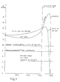
- Fig. 3 presents a diagram representing the torque available on the primary side of the gear in a solution according to previously known techniques and in the solution of the invention.
- Fig. 4 presents the disc chipper of the invention in top view, partly sectioned.
- Fig. 5 presents a cross-section of a spur gear assembly.
- Fig. 6 presents a top view of an embodiment of the invention provided with drive machines placed on either side of the chipping disc.
- the disc chipper is provided with a revolving chipping disc 1, which in this embodiment is mounted on a slightly inclined rotating axle 2.
- the chipping disc 1 consists of a steel plate rotating in a nearly vertical position and provided with radial or nearly radial holes produced in a known manner.
- the chipping blades (not shown) are attached to the rear edges of these holes, as seen in the direction of rotation.
- the chipping disc and its axle are supported by bearings on a fixed frame, which is also provided with a feed mouth 4 for feeding the logs onto the chipping disc.
- a counter blade At the bottom of the feed mouth, at a position closest to the chipping disc 1, is a counter blade (not shown) against which the log rests while chipped by the blades in the chipping disc.
- the chips are removed through an exit channel 6.
- the chipping disc 1 of the chipper is rotated by a drive machine 5, which in this embodiment comprises four motors 3 coupled to the axle 2.
- the motors are placed symmetrically about the imaginary extension of the axle in the rear part of the drive machine. More particularly, the motors are placed at 90° intervals on the same circle. Naturally, if three motors were used, they would be be placed at intervals of 120°.
- An advantageous motor power for each motor is e.g. 315 kW, in which case the total installed power of the disc chipper is 1260 kW.
- the motor power may vary, preferably between 200-400 kW, but the essential point is that the disc chipper of the invention can use smaller motors than earlier solutions.
- the curves in Fig. 3 represent the torque available on the primary side of the gear in a state-of-the-art solution and in the solution of the invention.
- a disc chipper with two motors of a nominal power of 800 kW has been selected.
- four standard motors with a nominal power of 315 kW each have been selected.
- the curves show that in this example the nominal torque in the case of previously known techniques is approx. 10 kNm and the nominal torque in the solution of the invention approx. 8 kNm.
- the maximum torque on the primary shaft in the conventional solution is considerably lower than when four smaller motors are used.
- a drawback with the previously known techniques is the need for fluid couplings, which considerably reduce the maximum torque. As stated before, no fluid couplings are needed in the solution of the invention.
- Fig. 4 shows the disc chipper of the invention partly sectioned and without the log feed and chip removal equipment.
- Fig. 4 is intended to illustrate the principle of power transmission from the motors 3 to the chipping disc 1.
- the shafts 7 of the motors 3 are provided with flexible couplings 8 to ensure an accurate positioning of the shafts. Further, the shafts 7 are connected to the primary gearwheels 9 of a spur gear assembly, and these engage the secondary gearwheel 10 via their toothing.
- the axle 11 of the secondary gearwheel is connected to the axle 2 of the chipping disc 1 via a toothed coupling 12.
- the latter axle 2 is supported by bearings 13 and 14. In this embodiment, no bearing is provided on the opposite side of the chipping disc, although there could be a bearing on that side as well.
- the embodiment illustrated by Fig. 4 has a provision for the installation of additional motors at points 15 and 16 on the opposite side of the gear assembly relative to the above-mentioned motors.
- the shafts of the additional motors are joined with those of the motors 3 on the opposite side and they thus drive the same primary gearwheels.
- Fig. 5 shows a cross-section of the spur gear assembly to illustrate how the motor shafts and the primary gearwheels 9 mounted on them are symmetrically placed around the secondary gearwheel 10 of the spur gear assembly.
- the primary gearwheels 9 are placed at 90° intervals on the same circle. The essential point is that the primary gearwheels are always placed at even distances, i.e. if there are five motors, the distance between primary gearwheels is 72°. In the case of three motors, the primary gearwheels are placed at 120° from each other, and so on.
- the toothings on the gearwheels 9, 10 are not shown in this illustration of the basic principle as they are considered to be obvious to a person skilled in the art.
- Fig. 5 is a greatly simplified representation.
- Fig. 6 ia a diagrammatic representation of an embodiment in which the axle 2 of the chipping disc 1 is supported by bearings 17 and 18 placed on either side of the disc, thus extending to both sides of it.
- This embodiment uses two drive machines 5 placed essentially symmetrically relative to the chipping disc.
- Each drive machine may comprise e.g. two motors 3, in which case the total number of motors is four. Naturally, the number of motors is not restricted to four in this or any other embodiment, but there may be three or more of them as needed.
Landscapes
- Engineering & Computer Science (AREA)
- Power Engineering (AREA)
- Mechanical Engineering (AREA)
- Life Sciences & Earth Sciences (AREA)
- Manufacturing & Machinery (AREA)
- Wood Science & Technology (AREA)
- Forests & Forestry (AREA)
- Debarking, Splitting, And Disintegration Of Timber (AREA)
- Crushing And Grinding (AREA)
- Diaphragms For Electromechanical Transducers (AREA)
- Peptides Or Proteins (AREA)
- Crushing And Pulverization Processes (AREA)
Abstract
Description
- The present invention relates to a disc chipper for the production of wood chips as defined in the introductory part of
claim 1. - The wood chips used as raw material in the production of chemical pulp and TMP (Thermo-Mechanical Pulp) is produced by chipping round wood by means of a chipper. Among the previously known types of chipper, the so-called disc chipper is the most commonly used.
- The basic structure of the disc chipper consists of a rotating chipping disc mounted on a horizontal or slightly inclined axle supported by bearings. The chipping disc is a steel plate rotating in a vertical or nearly vertical position. The disc is provided with radial or nearly radial holes and the chipping blades are attached to the rear edges of these holes, as seen in the direction of rotation. This disc and its axle are supported by bearings on a fixed frame, which is also provided with a feed mouth for feeding the logs onto the chipping disc. At the bottom of the feed mouth, at a position closest to the chipping disc, is a counter blade against which the log rests while chipped by the blades in the chipping disc.
- The chipping disc is rotated by means of a drive machine. This may be a synchronous motor connected to the axle by a coupling, in which case the disc has the same rotational speed as the motor. Another commonly used solution is one in which the motor is connected to the primary shaft of a gear connected to the chipper axle by a coupling, in which case the motor rotates at a higher speed than the disc. In another previously known disc drive, the gear has two primary shafts and two driving motors.
- The amount of energy required for the chipping depends on the strength of the wood and is different for different varieties of wood. Typical characteristic chipping energy levels for different types of wood variety:
- coniferous wood 6000 - 8000 kJ/m³ s.m.
- hardwood 8000 - 10000 kJ/m³ s.m.
- tropical special wood varieties 10000 - 12000 kJ/m³ s.m.
- When the wood variety to be chipped is known and the capacity of the chipping line has been determined, the power required by the chipper under normal circumstances can be calculated:
P = Q * p
where - Q =
- capacity [m³ s.m.]
- p =
- characteristic chipping energy [kJ/m³ s.m.]
- The maximum power required by the chipper occurs when a log of the maximum size is fed into it. The power can be calculated as follows:
Pmax = (D/2)² * π * l * Z * n * 60 * p
where - D =
- diameter of log [m]
- l =
- chip length [m]
- Z =
- number of chipping blades
- n =
- speed of rotation of the chipping disc [r/min]
- The chipping line capacity Q typically varies between 200-350 m³ s.m. /h, for which the average power requirement is 390-680 kW.
- Similarly, the maximum log diameter acceptable to the chipper is D = 800 - 900 mm. The number of chipping blades commonly used is 12 and the speed of rotation of the chipping disc 240 - 300 r/min. This means that the maximum power requirement in the case of coniferous wood and 24 mm chip length is 4050 - 6415 kW.
- From this it can be seen that the maximum power requirement is nearly tenfold as compared to the normal input power. In normal use, such high power levels are extremely seldom needed. The average diameter of logs used in the production of wood pulp varies from plant to plant between D = 100 - 250 mm. As the chipper must be able to handle even the occasional very big logs, the installed power of the chipper is determined by the maximum log size. The decisive factor is expressly the high torque required by the maximum log size, and the drive machine must be capable of generating a corresponding torque.
- The motor to be used with a chipper is selected by determining the torque required by the maximum log size. On the basis of this torque, the drive motor is so selected that the breakdown torque of the motor is higher than the required torque.
- For example, if:
- D =
- 800 mm (coniferous wood)
- l =
- 22 mm
- Z =
- 12 pcs
- n =
- 240 r/min
- P =
- 583 kW
- Pmax =
- 3715 kW
- Mmax =
- 147.84 kNm
- Choosing a gear with a transmission ratio of 6.25, which is advantageous because it allows a motor with the standard rotational speed of 1500 r/min to be used, means that the motor must be able to generate a torque of

- If a gear with two primary shafts is selected, the motor must be able to generate a torque of
Mm/2 = 11827 Nm
- This corresponds to a maximum motor power of

- If the motor has a break-down torque factor of 2, then standard motors are selected:
Pn = 1000 kW (2 pcs)
- Since the selection of motor size is based solely on the breakdown torque produced by the motor, the break-down torque factor of the motor plays an essential role in the determination of motor size.
- Because of questions of compatibility and spare parts, standard motors are generally preferred. In the standard motor series, motors in the lower power range (250-450 kW) are designed for higher breakdown torque factors than those in the highest power range (500-1000 kW).
- The object of the present invention is to achieve a disc chipper in which, among other things, the installed power is lower than before. This aim is realized by using several smaller motors instead of one or two big ones. For instance, the
motors 2 * 1000 kW in the drive in the calculation example above can be replaced with 4 * 400 kW motors. This results in a 400-kW reduction in the installed power, but because of the higher break-down torque factor of the motors, the maximum torque available is 3055 Nm higher and therefore the torque reserve larger. - More particularly, the invention is characterized by what is presented in the attached claims.
- The advantages of using several smaller motors include: lower installed power, lower starting current requirement resulting from sequential starting and providing advantages with respect to the power supply system of the motors. A further advantage is that the chipper can be started without fluid couplings on the motor shaft.
- In the following, the invention is described in detail by the aid of an example embodiment by referring to the attached drawing, in which
- Fig. 1 presents a schematic lateral view of the disc chipper of the invention.
- Fig. 2 presents the same in top view.
- Fig. 3 presents a diagram representing the torque available on the primary side of the gear in a solution according to previously known techniques and in the solution of the invention.
- Fig. 4 presents the disc chipper of the invention in top view, partly sectioned.
- Fig. 5 presents a cross-section of a spur gear assembly.
- Fig. 6 presents a top view of an embodiment of the invention provided with drive machines placed on either side of the chipping disc.
- The disc chipper is provided with a revolving
chipping disc 1, which in this embodiment is mounted on a slightly inclined rotatingaxle 2. Thechipping disc 1 consists of a steel plate rotating in a nearly vertical position and provided with radial or nearly radial holes produced in a known manner. The chipping blades (not shown) are attached to the rear edges of these holes, as seen in the direction of rotation. The chipping disc and its axle are supported by bearings on a fixed frame, which is also provided with afeed mouth 4 for feeding the logs onto the chipping disc. At the bottom of the feed mouth, at a position closest to thechipping disc 1, is a counter blade (not shown) against which the log rests while chipped by the blades in the chipping disc. The chips are removed through anexit channel 6. - The
chipping disc 1 of the chipper is rotated by adrive machine 5, which in this embodiment comprises fourmotors 3 coupled to theaxle 2. The motors are placed symmetrically about the imaginary extension of the axle in the rear part of the drive machine. More particularly, the motors are placed at 90° intervals on the same circle. Naturally, if three motors were used, they would be be placed at intervals of 120°. An advantageous motor power for each motor is e.g. 315 kW, in which case the total installed power of the disc chipper is 1260 kW. Naturally, the motor power may vary, preferably between 200-400 kW, but the essential point is that the disc chipper of the invention can use smaller motors than earlier solutions. - The curves in Fig. 3 represent the torque available on the primary side of the gear in a state-of-the-art solution and in the solution of the invention. As an example representing the state of the art, a disc chipper with two motors of a nominal power of 800 kW has been selected. As an example representing the present invention, four standard motors with a nominal power of 315 kW each have been selected. The curves show that in this example the nominal torque in the case of previously known techniques is approx. 10 kNm and the nominal torque in the solution of the invention approx. 8 kNm. However, in practice the maximum torque on the primary shaft in the conventional solution is considerably lower than when four smaller motors are used. A drawback with the previously known techniques is the need for fluid couplings, which considerably reduce the maximum torque. As stated before, no fluid couplings are needed in the solution of the invention.
- Fig. 4 shows the disc chipper of the invention partly sectioned and without the log feed and chip removal equipment. Fig. 4 is intended to illustrate the principle of power transmission from the
motors 3 to thechipping disc 1. Theshafts 7 of themotors 3 are provided withflexible couplings 8 to ensure an accurate positioning of the shafts. Further, theshafts 7 are connected to theprimary gearwheels 9 of a spur gear assembly, and these engage thesecondary gearwheel 10 via their toothing. Theaxle 11 of the secondary gearwheel is connected to theaxle 2 of thechipping disc 1 via atoothed coupling 12. Thelatter axle 2 is supported bybearings - Furthermore, the embodiment illustrated by Fig. 4 has a provision for the installation of additional motors at
points motors 3 on the opposite side and they thus drive the same primary gearwheels. - Fig. 5 shows a cross-section of the spur gear assembly to illustrate how the motor shafts and the
primary gearwheels 9 mounted on them are symmetrically placed around thesecondary gearwheel 10 of the spur gear assembly. In this embodiment, theprimary gearwheels 9 are placed at 90° intervals on the same circle. The essential point is that the primary gearwheels are always placed at even distances, i.e. if there are five motors, the distance between primary gearwheels is 72°. In the case of three motors, the primary gearwheels are placed at 120° from each other, and so on. The toothings on thegearwheels - Fig. 6 ia a diagrammatic representation of an embodiment in which the
axle 2 of thechipping disc 1 is supported bybearings drive machines 5 placed essentially symmetrically relative to the chipping disc. Each drive machine may comprise e.g. twomotors 3, in which case the total number of motors is four. Naturally, the number of motors is not restricted to four in this or any other embodiment, but there may be three or more of them as needed. - It is obvious to a person skilled in the art that different embodiments of the invention are not restricted to the examples described above, but that they may instead be varied within the scope of the following claims. Thus it is obvious that instead of an oblique position, the disc chipper can just as well be mounted in a horizontal position, in which case the chipping disc has an essentially vertical position. The gearing between the motor shafts and the chipping disc axle need not be a spur gear assembly, although this seems to be the most advantageous solution. Another possible alternative is e.g. a bevel gear assembly. Furthermore, it is not necessary for all the motors to be of the same size, although this must be regarded as the preferable solution.
where m³ s.m. means solid meters.
and the chipping line capacity is assumed to be Q = 300 m³ s.m. /h,
then
Claims (5)
- Disc chipper for the production of wood chips, consisting of a rotatable chipping disc (1), the axle (2) of the chipping disc and a drive machine (5) rotating the axle, characterized in that the drive machine (5) is provided with at least three electric standard motors (3) which rotate the axle (2) of the chipping disc (1) by means of a gear assembly, preferably a spur gear assembly.
- Disc chipper according to claim 1, characterized in that it has four motors and that the motors are arranged symmetrically about the axle (2) or its imaginary extension.
- Disc chipper according to claim 2, characterized in that each motor has a power of approx. 200-400 kW, e.g. 315 kW.
- Disc chipper according to claim 1, characterized in that the axle (2) of the chipping disc (1) is supported by bearings on both sides of the chipping disc, and that the chipper has a gear assembly (9, 10) and a drive machine (5) connected to the axle on each side of the chipping disc, each drive machine being provided with e.g. two motors (3).
- Disc chipper according to claim 1, characterized in that it has additional motors arranged coaxially with motors (3) on the opposite side of the gear assembly (9, 10), the shaft of each additional motor being connected to the same primary gearwheel (9) as the shaft (7) of the motor (3) on the opposite side of the gear assembly.
Priority Applications (1)
| Application Number | Priority Date | Filing Date | Title |
|---|---|---|---|
| AT91107642T ATE102116T1 (en) | 1990-05-18 | 1991-05-10 | CHIP DISC FOR THE PRODUCTION OF WOOD SHAVINGS. |
Applications Claiming Priority (2)
| Application Number | Priority Date | Filing Date | Title |
|---|---|---|---|
| FI902482 | 1990-05-18 | ||
| FI902482A FI85348C (en) | 1990-05-18 | 1990-05-18 | SKIVHUGG FOER FRAMSTAELLNING AV FLIS |
Publications (3)
| Publication Number | Publication Date |
|---|---|
| EP0457216A2 EP0457216A2 (en) | 1991-11-21 |
| EP0457216A3 EP0457216A3 (en) | 1992-04-29 |
| EP0457216B1 true EP0457216B1 (en) | 1994-03-02 |
Family
ID=8530463
Family Applications (1)
| Application Number | Title | Priority Date | Filing Date |
|---|---|---|---|
| EP91107642A Expired - Lifetime EP0457216B1 (en) | 1990-05-18 | 1991-05-10 | Disc chipper for the production of wood chips |
Country Status (6)
| Country | Link |
|---|---|
| US (1) | US5094280A (en) |
| EP (1) | EP0457216B1 (en) |
| AT (1) | ATE102116T1 (en) |
| CA (1) | CA2042728C (en) |
| DE (1) | DE69101259T2 (en) |
| FI (1) | FI85348C (en) |
Families Citing this family (10)
| Publication number | Priority date | Publication date | Assignee | Title |
|---|---|---|---|---|
| US5417263A (en) * | 1993-08-11 | 1995-05-23 | Jorgensen; Ray B. | Log chipper for lowering peak power requirements and raising chip quality |
| FI99279C (en) * | 1996-06-18 | 1998-05-11 | Andritz Patentverwaltung | Cutting disc into a disc |
| US5680998A (en) * | 1996-08-01 | 1997-10-28 | Altec Industries, Inc. | Brush chipping machine with in-line drive system |
| US6595172B2 (en) * | 2001-05-14 | 2003-07-22 | Delphi Technologies, Inc. | Variable valve actuator assembly having a secondary actuator |
| FI127012B (en) * | 2017-01-19 | 2017-09-29 | Dieffenbacher Panelboard Oy | Turning equipment for a cooling unit |
| US11940153B2 (en) * | 2020-12-01 | 2024-03-26 | GMG Products, LLC | Fuel conditioner for grill |
| AU2022444183A1 (en) | 2022-03-03 | 2024-10-10 | GMG Products, LLC | Grill |
| US12289508B2 (en) | 2022-03-18 | 2025-04-29 | GMG Products, LLC | Detachable camera for a smoker or grill |
| WO2024227004A1 (en) * | 2023-04-26 | 2024-10-31 | Black & Decker Inc. | Circular saw |
| US12359808B1 (en) | 2024-04-30 | 2025-07-15 | GMG Products, LLC | Variable fuel cooker |
Family Cites Families (9)
| Publication number | Priority date | Publication date | Assignee | Title |
|---|---|---|---|---|
| BE503760A (en) * | ||||
| US3545510A (en) * | 1968-09-30 | 1970-12-08 | Thomas P Bush Jr | Method and apparatus for chipping logs |
| DE1953146A1 (en) * | 1969-10-17 | 1971-04-29 | Siemens Ag | Drive of a working machine via gear |
| US3810555A (en) * | 1972-08-16 | 1974-05-14 | Air Preheater | Railroad tie reducer |
| CA967458A (en) * | 1972-09-05 | 1975-05-13 | Nicholson Murdie Machines Ltd. | Overhung disk chipper |
| US4098139A (en) * | 1976-12-15 | 1978-07-04 | Marion Power Shovel Company, Inc. | Gear train and method of aligning component gears thereof |
| DE3407593A1 (en) * | 1984-03-01 | 1985-09-05 | Gesellschaft für Kernverfahrenstechnik mbH, 5170 Jülich | DRIVE FOR CENTRIFUGES |
| JPS6277083A (en) * | 1985-09-30 | 1987-04-09 | Nissan Motor Co Ltd | Controlling device for motor |
| JPH0622829B2 (en) * | 1986-06-30 | 1994-03-30 | フアナツク株式会社 | Direct pressure type mold clamping mechanism |
-
1990
- 1990-05-18 FI FI902482A patent/FI85348C/en active IP Right Grant
-
1991
- 1991-05-10 EP EP91107642A patent/EP0457216B1/en not_active Expired - Lifetime
- 1991-05-10 DE DE69101259T patent/DE69101259T2/en not_active Expired - Fee Related
- 1991-05-10 AT AT91107642T patent/ATE102116T1/en not_active IP Right Cessation
- 1991-05-16 CA CA002042728A patent/CA2042728C/en not_active Expired - Lifetime
- 1991-05-17 US US07/701,907 patent/US5094280A/en not_active Expired - Lifetime
Also Published As
| Publication number | Publication date |
|---|---|
| DE69101259T2 (en) | 1994-06-09 |
| FI85348B (en) | 1991-12-31 |
| ATE102116T1 (en) | 1994-03-15 |
| FI902482A7 (en) | 1991-11-19 |
| EP0457216A3 (en) | 1992-04-29 |
| FI902482A0 (en) | 1990-05-18 |
| CA2042728A1 (en) | 1991-11-19 |
| US5094280A (en) | 1992-03-10 |
| FI85348C (en) | 1993-11-08 |
| CA2042728C (en) | 1994-10-25 |
| DE69101259D1 (en) | 1994-04-07 |
| EP0457216A2 (en) | 1991-11-21 |
Similar Documents
| Publication | Publication Date | Title |
|---|---|---|
| US4694915A (en) | Slotted wall milling cutter | |
| EP0457216A2 (en) | Disc chipper for the production of wood chips | |
| GB2197009A (en) | Drilling boreholes | |
| US6497376B2 (en) | Cutting device | |
| US1312450A (en) | Disintegrating and conserving mechanism | |
| EP0264413B1 (en) | Chipper | |
| CN218286171U (en) | Saw cutting device assembly | |
| US20060006259A1 (en) | Comminuting apparatus | |
| CA1056278A (en) | Waferizer | |
| US11980949B2 (en) | Drilling machine | |
| CN216609378U (en) | A swift tooth equipment that cuts for comb processing | |
| CN213320690U (en) | A waste wood processing apparatus for after wood furniture processing | |
| CA2306721C (en) | Apparatus for reducing the oversized fraction of chips | |
| CN215197337U (en) | Financial transaction centralized processing device | |
| CN210616839U (en) | Wood chipper | |
| CN210500694U (en) | High-precision numerical control pore-forming tapping system for wooden furniture | |
| RU97100478A (en) | DEVICE FOR CUTTING ROLLS OF INSULATION TAPE | |
| CN212241252U (en) | Slicing machine capable of slicing flatly | |
| SU1036473A1 (en) | Shaft working machine | |
| RU8298U1 (en) | LOG OUTDOOR DEVICE | |
| SU651949A1 (en) | Rotary type barking-stripping machine | |
| JPH0214882B2 (en) | ||
| CN107552678A (en) | Thread planer blade roll forming equipment | |
| SU1194604A1 (en) | Apparatus for cutting rolled stock | |
| SU337251A1 (en) | DISTRIBUTION INSTALLATION |
Legal Events
| Date | Code | Title | Description |
|---|---|---|---|
| PUAI | Public reference made under article 153(3) epc to a published international application that has entered the european phase |
Free format text: ORIGINAL CODE: 0009012 |
|
| AK | Designated contracting states |
Kind code of ref document: A2 Designated state(s): AT DE FR SE |
|
| PUAL | Search report despatched |
Free format text: ORIGINAL CODE: 0009013 |
|
| AK | Designated contracting states |
Kind code of ref document: A3 Designated state(s): AT DE FR SE |
|
| 17P | Request for examination filed |
Effective date: 19920430 |
|
| 17Q | First examination report despatched |
Effective date: 19930726 |
|
| GRAA | (expected) grant |
Free format text: ORIGINAL CODE: 0009210 |
|
| AK | Designated contracting states |
Kind code of ref document: B1 Designated state(s): AT DE FR SE |
|
| REF | Corresponds to: |
Ref document number: 102116 Country of ref document: AT Date of ref document: 19940315 Kind code of ref document: T |
|
| REF | Corresponds to: |
Ref document number: 69101259 Country of ref document: DE Date of ref document: 19940407 |
|
| ET | Fr: translation filed | ||
| PLBE | No opposition filed within time limit |
Free format text: ORIGINAL CODE: 0009261 |
|
| STAA | Information on the status of an ep patent application or granted ep patent |
Free format text: STATUS: NO OPPOSITION FILED WITHIN TIME LIMIT |
|
| EAL | Se: european patent in force in sweden |
Ref document number: 91107642.0 |
|
| 26N | No opposition filed | ||
| REG | Reference to a national code |
Ref country code: FR Ref legal event code: TP |
|
| PGFP | Annual fee paid to national office [announced via postgrant information from national office to epo] |
Ref country code: SE Payment date: 20090514 Year of fee payment: 19 Ref country code: AT Payment date: 20090515 Year of fee payment: 19 Ref country code: DE Payment date: 20090525 Year of fee payment: 19 Ref country code: FR Payment date: 20090513 Year of fee payment: 19 |
|
| PG25 | Lapsed in a contracting state [announced via postgrant information from national office to epo] |
Ref country code: AT Free format text: LAPSE BECAUSE OF NON-PAYMENT OF DUE FEES Effective date: 20100510 |
|
| EUG | Se: european patent has lapsed | ||
| REG | Reference to a national code |
Ref country code: FR Ref legal event code: ST Effective date: 20110131 |
|
| PG25 | Lapsed in a contracting state [announced via postgrant information from national office to epo] |
Ref country code: SE Free format text: LAPSE BECAUSE OF NON-PAYMENT OF DUE FEES Effective date: 20100511 |
|
| PG25 | Lapsed in a contracting state [announced via postgrant information from national office to epo] |
Ref country code: DE Free format text: LAPSE BECAUSE OF NON-PAYMENT OF DUE FEES Effective date: 20101201 |
|
| PG25 | Lapsed in a contracting state [announced via postgrant information from national office to epo] |
Ref country code: FR Free format text: LAPSE BECAUSE OF NON-PAYMENT OF DUE FEES Effective date: 20100531 |