EP0456398B1 - Cooling of electronic equipment cabinets - Google Patents
Cooling of electronic equipment cabinets Download PDFInfo
- Publication number
- EP0456398B1 EP0456398B1 EP91303870A EP91303870A EP0456398B1 EP 0456398 B1 EP0456398 B1 EP 0456398B1 EP 91303870 A EP91303870 A EP 91303870A EP 91303870 A EP91303870 A EP 91303870A EP 0456398 B1 EP0456398 B1 EP 0456398B1
- Authority
- EP
- European Patent Office
- Prior art keywords
- cabinet
- air
- shelves
- fan
- door
- Prior art date
- Legal status (The legal status is an assumption and is not a legal conclusion. Google has not performed a legal analysis and makes no representation as to the accuracy of the status listed.)
- Expired - Lifetime
Links
Images



Classifications
-
- H—ELECTRICITY
- H05—ELECTRIC TECHNIQUES NOT OTHERWISE PROVIDED FOR
- H05K—PRINTED CIRCUITS; CASINGS OR CONSTRUCTIONAL DETAILS OF ELECTRIC APPARATUS; MANUFACTURE OF ASSEMBLAGES OF ELECTRICAL COMPONENTS
- H05K7/00—Constructional details common to different types of electric apparatus
- H05K7/20—Modifications to facilitate cooling, ventilating, or heating
- H05K7/20536—Modifications to facilitate cooling, ventilating, or heating for racks or cabinets of standardised dimensions, e.g. electronic racks for aircraft or telecommunication equipment
- H05K7/206—Air circulating in closed loop within cabinets wherein heat is removed through air-to-air heat-exchanger
Definitions
- This invention relates to cooling of electronic components.
- Such cooling techniques while generally adequate, are not necessarily effective in cases where a large number of high density circuit packs must be housed within a fairly small space, as in the case of subscriber loop carrier (SLC®) remote terminal channel banks.
- SLC® subscriber loop carrier
- Such banks typically include channel units and common units which are each capable of generating up to 10 watts of heat.
- These circuit packs are mounted vertically with, typically, 28 circuit packs per shelf and 5 shelves per bank.
- banks are housed back-to-back in a cabinet with a small space between them.
- the present method generally employed to cool unvented cabinets, which is to blow air into the banks, has reached the limit of its effectiveness. Attempts to increase cooling have generally involved use of heat pipes or finned heat exchangers without addressing the optimization of airflow within the cabinet.
- the invention in accordance with one aspect, is a cabinet comprising: a fan mounted to said cabinet so as to be capable of drawing air in a vertical direction; means for providing recirculation of the air in a vertical direction opposite to the direction of air drawn by the fan, said means including a plate member mounted to the inside of a door of said cabinet to form a duct for recirculation of the air adjacent to a surface of said door so as to provide cooling of the air by said surface of the door, the fan being mounted to be capable of blowing air into the duct; and a plurality of shelves mounted to said cabinet with a side positioned adjacent to said plate member and vertically spaced from said fan; wherein a heat exchanging element is mounted to said cabinet and positioned adjacent to a side of said shelves opposite to said door, as defined in claim 1.
- the invention is a cabinet comprising: a fan mounted to said cabinet so as to be capable of drawing air in a vertical direction; means mounted to said cabinet for directing the air in an opposite vertical direction; and a plurality of vertically stacked shelves mounted to the cabinet with one side positioned adjacent to a door for providing access to said shelves; wherein a heat exchanging element (30) is mounted to said cabinet and positioned adjacent a side of the shelves opposite to the door in a relationship to the fan so that air which is directed in the opposite vertical direction can be cooled by the heat exchanging element, said heat exchanging element comprising means (32) for drawing air from outside the cabinet through a plurality of compartments (36,37,38) in said element so as to provide a cooling surface (34) for the air in a space adjacent to said surface, as defined in claim 8.
- a cabinet in accordance with the preambles of claims 1 and 8 is known from DD-A-212871.
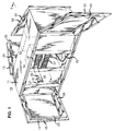
- FIG. 1 illustrates a cabinet including cooling means, useful for understanding the invention.
- the cabinet 10 includes a housing 11 and four doors 12, 13, 50 and 51 hinged on opposite surfaces of the housing.
- the electronic equipment protected by the housing includes banks 14 and 15 of circuit packs, e.g., 16, mounted in shelves, e.g., 17 and 18. Although not shown, multiple banks can be mounted in a cabinet position, e.g., one above the other.
- the front of the circuit packs of the two banks 14 and 15 face in opposite directions so as to be accessible by opening different doors.
- the circuit packs are of a standard type which include components, e.g., 19, formed on a circuit board 20 with a faceplate 21 at the front end for latching the board into the shelf. It will be appreciated that the full number of shelves, as well as other standard components on a remote terminal cabinet, such as protector blocks, power components, and wiring, have been omitted for the sake of clarity in the illustration.
- a shelf including a fan (22 and 27 of FIG. 2) mounted so as to draw air down through the spaces between the circuit packs in the bank.
- Plates 23, 24, 52 and 53 are mounted in a spaced relationship with each door, 12, 13, 50 and 51, respectively, to provide ducts, e.g., 25 and 26 of doors 12 and 13, for recirculating air as described in more detail below.
- each plate covered essentially the entire inside surface of its respective door and was mounted to the door by screws and standoffs, but any standard mounting arrangement can be employed.
- the plates were made of aluminum, but other materials can also be used.
- the ducts formed between the plates and the doors were approximately 3 cm wide.
- Each plate also included a horizontal baffle, e.g., 56, mounted to a bottom portion of the plate by standard means.
- FIG. 2 is a schematic cross-sectional view along line 2-2 of FIG. 1, with the doors in a closed position, illustrating the flow of air through the cabinet when the fans are turned on.
- Each rectangular block, e.g., 16, represents a channel bank (typically 5 shelves of circuit packs).
- the fans 22 and 27 draw air down through the banks of circuit packs as indicated by the arrows.
- the air is then recirculated through the ducts 25 and 26 formed between the plates 23 and 24 and the doors 12 and 13.
- the ducts prevent the recirculating air from entering the spaces between the faceplates of the circuit packs since the plates extend essentially the entire vertical distance occupied by the circuit packs.
- FIG. 3 illustrates a cabinet which further enhances cooling capabilities.
- the cabinet is essentially the same as that illustrated in FIG. 1 except for the addition of a heat exchange element 30.
- This element is inserted in a side surface of the housing and extends into the spaces between the banks 14 and 15.
- This element includes a metal housing 31 providing heat exchanging surfaces adjacent to each bank, and means such as fans 32 and 33 for bringing in air from the outside environment and exhausting the air back to the outside environment.
- the housing can include metal fins, e.g., 54, for increased heat exchange.
- air brought in by fan 32 is circulated through three different main compartments 36-38 formed by U-shaped baffles 39, 40 and 41 as well as secondary compartments formed by vertical plates, e.g., 42.
- the air is then exhausted through fan 33.
- This air flow produces finned heat exchange surfaces 34 and 35 which are utilized for cooling the cabinet as shown in FIG. 5, which is a cross-sectional view along line 5-5 of FIG. 3.
- air is drawn vertically through the spaces between circuit packs in the banks by the fans 22 and 27.
- part of the air is also recirculated in the spaces (43 and 44 of FIG. 3) between the banks which contain finned surfaces 34 and 35 of the heat exchanger element 30.
- the spaces 43 and 44 are approximately 3 cm wide.
- the recirculating air is cooled by the heat exchange surface, 34 and 35 as it traverses upward. (The air is prevented from entering the spaces between circuit packs in its upward path by the usual backplane provided for electrically interconnecting the circuit packs). The cooled air can then be drawn downward again to cool the circuit packs.
- FIGS. 3-5 should permit additional heat exchange capabilities over the cabinet of FIGS. 1-2.
Landscapes
- Engineering & Computer Science (AREA)
- Aviation & Aerospace Engineering (AREA)
- Physics & Mathematics (AREA)
- Thermal Sciences (AREA)
- Microelectronics & Electronic Packaging (AREA)
- Cooling Or The Like Of Electrical Apparatus (AREA)
Description
- This invention relates to cooling of electronic components.
- Higher heat densities in electronic equipment caused by the increasing density of integrated circuits and circuit pack configurations, has led to concern regarding the ability of unvented outdoor electronic cabinets to dissipate the heat generated by the electronics. The equipment is usually housed in shelves within an appropriate cabinet and cooled by fans. Fans can be adapted to blow recirculated coolant onto the components through a series of ducts (see, e.g., U.S. -A- 3,387,648). Alternatively, a fan can draw air from outside the cabinet through openings in a wall of the cabinet and direct it over the components (see, e.g., U.S. -A- 4,027,206). Appropriate ducts can also be used to guide the air (see, e.g., U.S. -A- 4,860,163).
- Such cooling techniques, while generally adequate, are not necessarily effective in cases where a large number of high density circuit packs must be housed within a fairly small space, as in the case of subscriber loop carrier (SLC®) remote terminal channel banks. Such banks typically include channel units and common units which are each capable of generating up to 10 watts of heat. These circuit packs are mounted vertically with, typically, 28 circuit packs per shelf and 5 shelves per bank. Usually, banks are housed back-to-back in a cabinet with a small space between them.
- The present method generally employed to cool unvented cabinets, which is to blow air into the banks, has reached the limit of its effectiveness. Attempts to increase cooling have generally involved use of heat pipes or finned heat exchangers without addressing the optimization of airflow within the cabinet.
- The invention, in accordance with one aspect, is a cabinet comprising:
a fan mounted to said cabinet so as to be capable of drawing air in a vertical direction;
means for providing recirculation of the air in a vertical direction opposite to the direction of air drawn by the fan, said means including a plate member mounted to the inside of a door of said cabinet to form a duct for recirculation of the air adjacent to a surface of said door so as to provide cooling of the air by said surface of the door, the fan being mounted to be capable of blowing air into the duct; and
a plurality of shelves mounted to said cabinet with a side positioned adjacent to said plate member and vertically spaced from said fan;
wherein
a heat exchanging element is mounted to said cabinet and positioned adjacent to a side of said shelves opposite to said door, as defined in claim 1. - In accordance with another aspect, the invention is a cabinet comprising:
a fan mounted to said cabinet so as to be capable of drawing air in a vertical direction;
means mounted to said cabinet for directing the air in an opposite vertical direction; and
a plurality of vertically stacked shelves mounted to the cabinet with one side positioned adjacent to a door for providing access to said shelves;
wherein
a heat exchanging element (30) is mounted to said cabinet and positioned adjacent a side of the shelves opposite to the door in a relationship to the fan so that air which is directed in the opposite vertical direction can be cooled by the heat exchanging element, said heat exchanging element comprising means (32) for drawing air from outside the cabinet through a plurality of compartments (36,37,38) in said element so as to provide a cooling surface (34) for the air in a space adjacent to said surface, as defined in claim 8. - A cabinet in accordance with the preambles of claims 1 and 8 is known from DD-A-212871.
- These and other features of the invention are delineated in detail in the following description. In the drawing:
- FIG. 1 is a perspective view of a cabinet including cooling means useful for understanding the invention;
- FIG. 2 is a cross-sectional schematic view of the cabinet of FIG. 1 taken along line 2-2;
- FIG. 3 is a perspective view of a cabinet including cooling means in accordance with an embodiment of the invention;
- FIG. 4 is a cross-sectional schematic view of a portion of the cooling means of FIG. 3 taken along line 4-4; and
- FIG. 5 is a cross-sectional schematic view of the cabinet of FIG. 3 taken along line 5-5.
- It will be appreciated that, for purposes of illustration, these figures are not necessarily drawn to scale.
- FIG. 1 illustrates a cabinet including cooling means, useful for understanding the invention. The
cabinet 10 includes ahousing 11 and fourdoors banks banks circuit board 20 with afaceplate 21 at the front end for latching the board into the shelf. It will be appreciated that the full number of shelves, as well as other standard components on a remote terminal cabinet, such as protector blocks, power components, and wiring, have been omitted for the sake of clarity in the illustration. - At the bottom of each mounting position in the cabinet is a shelf including a fan (22 and 27 of FIG. 2) mounted so as to draw air down through the spaces between the circuit packs in the bank. The applicants discovered that drawing the air through the bank was more effective than blowing air into the bank in terms of exchanging heat between the air and the heat generating components.
-
Plates doors - FIG. 2 is a schematic cross-sectional view along line 2-2 of FIG. 1, with the doors in a closed position, illustrating the flow of air through the cabinet when the fans are turned on. Each rectangular block, e.g., 16, represents a channel bank (typically 5 shelves of circuit packs). As previously mentioned, the
fans ducts plates doors ducts doors vertical baffles shelves including fans - Utilizing this technique, it was discovered that the rise in temperature of the hottest circuit packs was lowered by approximately 40 percent over prior schemes which forced air into the channel banks without using a door duct.
- FIG. 3 illustrates a cabinet which further enhances cooling capabilities. The cabinet is essentially the same as that illustrated in FIG. 1 except for the addition of a
heat exchange element 30. This element is inserted in a side surface of the housing and extends into the spaces between thebanks metal housing 31 providing heat exchanging surfaces adjacent to each bank, and means such asfans - As illustrated by the arrows in the cross-sectional view of the element in FIG. 4, air brought in by
fan 32 is circulated through three different main compartments 36-38 formed byU-shaped baffles fan 33. - This air flow produces finned heat exchange surfaces 34 and 35 which are utilized for cooling the cabinet as shown in FIG. 5, which is a cross-sectional view along line 5-5 of FIG. 3. Again, air is drawn vertically through the spaces between circuit packs in the banks by the
fans ducts surfaces heat exchanger element 30. In this example, thespaces - Thus, the embodiment shown in FIGS. 3-5 should permit additional heat exchange capabilities over the cabinet of FIGS. 1-2.
Claims (11)
- A cabinet (10), comprising:
a fan (22) mounted to said cabinet so as to be capable of drawing air in a vertical direction;
means for providing recirculation of the air in a vertical direction opposite to the direction of air drawn by the fan, said means including a plate member (23) mounted to the inside of a door of said cabinet to form a duct (25) for recirculation of the air adjacent to a surface of said door so as to provide cooling of the air by said surface of the door, the fan being mounted to be capable of blowing air into the duct; and
a plurality of shelves (17,18) mounted to said cabinet with a side positioned adjacent to said plate member and vertically spaced from said fan;
CHARACTERIZED IN THAT
a heat exchanging element (30) is mounted to said cabinet and positioned adjacent to a side of said shelves opposite to said door. - The cabinet according to claim 1 further comprising electronic equipment which includes a plurality of circuit packs (16) positioned in said shelves (17,18) mounted to said cabinet so that the air is drawn in vertical spaces between the circuit packs.
- The cabinet according to claim 2 wherein the electronic equipment includes a plurality of banks (14 and 15) of circuit packs and a plurality of doors (12,13,50, and 51) mounted to said cabinet for providing access to the banks, each of said doors including a plate element (23,24,52 and 53) mounted to an inside surface.
- The cabinet according to claim 1 wherein the plate member extends a vertical distance essentially co-extensive with said plurality of shelves.
- The cabinet according to claim 3 wherein the heat exchanging element (30) mounted to said cabinet is positioned in a space between two banks (14 and 15) so that the banks are between the element and the doors.
- The cabinet according to claim 1 further comprising a baffle mounted at a bottom portion of the plate member (23).
- The cabinet according to claim 1 further comprising a second plurality of shelves with a side adjacent to another plate member (24) mounted to another door (13) of the cabinet, the heat exchanging element being mounted in a space between the two pluralities of shelves.
- A cabinet (10) comprising:
a fan (22) mounted to said cabinet so as to be capable of drawing air in a vertical direction;
means mounted to said cabinet for directing the air in an opposite vertical direction; and
a plurality of vertically stacked shelves (e.g., 17 and 18) mounted to the cabinet with one side positioned adjacent to a door for providing access to said shelves;
CHARACTERIZED IN THAT
a heat exchanging element (30) is mounted to said cabinet and positioned adjacent a side of the shelves opposite to the door in a relationship to the fan so that air which is directed in the opposite vertical direction can be cooled by the heat exchanging element, said heat exchanging element comprising means (32) for drawing air from outside the cabinet through a plurality of compartments (36,37,38) in said element so as to provide a cooling surface (34) for the air in a space adjacent to said surface. - The cabinet according to claim 8 further comprising a plurality of banks (14,15) of circuit packs (16), positioned within said shelves mounted to said cabinet with the heat exchanging element positioned in a space between the banks.
- The cabinet according to claim 8 wherein the means for drawing air from outside the cabinet comprises a first fan (32) mounted to said element at an input portion of the compartments, and further comprising an exhaust fan (33) mounted to said element at an output portion of the compartments.
- The cabinet according to claim 8 wherein the compartments are defined by U-shaped baffles (39,40,41) and vertical plates (42) mounted to said element.
Applications Claiming Priority (2)
| Application Number | Priority Date | Filing Date | Title |
|---|---|---|---|
| US51905090A | 1990-05-04 | 1990-05-04 | |
| US519050 | 1995-08-24 |
Publications (3)
| Publication Number | Publication Date |
|---|---|
| EP0456398A2 EP0456398A2 (en) | 1991-11-13 |
| EP0456398A3 EP0456398A3 (en) | 1991-11-21 |
| EP0456398B1 true EP0456398B1 (en) | 1995-07-19 |
Family
ID=24066574
Family Applications (1)
| Application Number | Title | Priority Date | Filing Date |
|---|---|---|---|
| EP91303870A Expired - Lifetime EP0456398B1 (en) | 1990-05-04 | 1991-04-29 | Cooling of electronic equipment cabinets |
Country Status (6)
| Country | Link |
|---|---|
| EP (1) | EP0456398B1 (en) |
| JP (1) | JP3276640B2 (en) |
| AU (1) | AU626026B2 (en) |
| CA (1) | CA2036164C (en) |
| DE (1) | DE69111295T2 (en) |
| ES (1) | ES2074659T3 (en) |
Cited By (1)
| Publication number | Priority date | Publication date | Assignee | Title |
|---|---|---|---|---|
| RU2780363C1 (en) * | 2021-11-08 | 2022-09-22 | Акционерное общество "Концерн "Центральный научно-исследовательский институт "Электроприбор" | Radio electronic equipment cabinet |
Families Citing this family (8)
| Publication number | Priority date | Publication date | Assignee | Title |
|---|---|---|---|---|
| GB2284659A (en) * | 1993-11-22 | 1995-06-14 | Malcoe Precision Fabrications | Electrical apparatus enclosure with cooling air circulated in a closed path |
| SE505272C2 (en) * | 1994-12-14 | 1997-07-28 | Ericsson Telefon Ab L M | Cooling system for telecommunications equipment |
| DE29704237U1 (en) * | 1997-03-08 | 1997-05-28 | DMT GmbH Feinwerktechnische Komplettlösungen, 71034 Böblingen | Device housing |
| RU2213436C2 (en) * | 2001-01-19 | 2003-09-27 | Дагестанский государственный технический университет | Device for cooling down radio equipment components intermittently releasing heat |
| RU2236096C2 (en) * | 2001-11-29 | 2004-09-10 | Дагестанский государственный технический университет | Device for temperature control of high-power radio equipment components |
| RU2236097C2 (en) * | 2001-11-29 | 2004-09-10 | Дагестанский государственный технический университет | Device for temperature control of high-power radio equipment components |
| EP1454218A1 (en) * | 2002-04-06 | 2004-09-08 | Zalman Tech Co., Ltd. | Chipset cooling device of video graphic adapter card |
| RU2459231C2 (en) * | 2010-09-30 | 2012-08-20 | Государственное образовательное учреждение высшего профессионального образования Томский государственный университет систем управления и радиоэлектроники (ТУСУР) | Device to stabilise temperature of microassemblies |
Citations (1)
| Publication number | Priority date | Publication date | Assignee | Title |
|---|---|---|---|---|
| DD212871A1 (en) * | 1982-12-21 | 1984-08-22 | Elektroprojekt Anlagenbau Veb | ARRANGEMENT FOR HEAT EXTRACTION FROM CLOSED GEHAEUSEN |
Family Cites Families (7)
| Publication number | Priority date | Publication date | Assignee | Title |
|---|---|---|---|---|
| US3387648A (en) * | 1967-02-23 | 1968-06-11 | Navy Usa | Cabinet enclosed recirculation cooling system carried on extensible chassis mountingelectronic modules |
| US4027206A (en) * | 1975-01-27 | 1977-05-31 | L. H. Research | Electronic cooling chassis |
| JPS5911654A (en) * | 1982-07-12 | 1984-01-21 | Kansai Electric Power Co Inc:The | Series-parallel flow cooling device |
| EP0225954A1 (en) * | 1985-12-18 | 1987-06-24 | Alcan International Limited | Protection for control equipment |
| DE3721901A1 (en) * | 1987-07-02 | 1989-01-12 | Heidelberger Druckmasch Ag | SWITCH CABINET |
| GB8724263D0 (en) * | 1987-10-15 | 1987-11-18 | Bicc Plc | Electronic enclosure cooling system |
| US4860163A (en) * | 1988-08-05 | 1989-08-22 | American Telephone And Telegraph Company | Communication equipment cabinet cooling arrangement |
-
1991
- 1991-02-12 CA CA 2036164 patent/CA2036164C/en not_active Expired - Fee Related
- 1991-04-16 AU AU75103/91A patent/AU626026B2/en not_active Ceased
- 1991-04-29 DE DE1991611295 patent/DE69111295T2/en not_active Expired - Fee Related
- 1991-04-29 ES ES91303870T patent/ES2074659T3/en not_active Expired - Lifetime
- 1991-04-29 EP EP91303870A patent/EP0456398B1/en not_active Expired - Lifetime
- 1991-05-01 JP JP09935891A patent/JP3276640B2/en not_active Expired - Fee Related
Patent Citations (1)
| Publication number | Priority date | Publication date | Assignee | Title |
|---|---|---|---|---|
| DD212871A1 (en) * | 1982-12-21 | 1984-08-22 | Elektroprojekt Anlagenbau Veb | ARRANGEMENT FOR HEAT EXTRACTION FROM CLOSED GEHAEUSEN |
Cited By (1)
| Publication number | Priority date | Publication date | Assignee | Title |
|---|---|---|---|---|
| RU2780363C1 (en) * | 2021-11-08 | 2022-09-22 | Акционерное общество "Концерн "Центральный научно-исследовательский институт "Электроприбор" | Radio electronic equipment cabinet |
Also Published As
| Publication number | Publication date |
|---|---|
| AU7510391A (en) | 1991-11-07 |
| AU626026B2 (en) | 1992-07-23 |
| DE69111295T2 (en) | 1996-01-11 |
| DE69111295D1 (en) | 1995-08-24 |
| JPH04271195A (en) | 1992-09-28 |
| EP0456398A3 (en) | 1991-11-21 |
| CA2036164A1 (en) | 1991-11-05 |
| ES2074659T3 (en) | 1995-09-16 |
| EP0456398A2 (en) | 1991-11-13 |
| JP3276640B2 (en) | 2002-04-22 |
| CA2036164C (en) | 1998-07-07 |
Similar Documents
| Publication | Publication Date | Title |
|---|---|---|
| US5150277A (en) | Cooling of electronic equipment cabinets | |
| US11880247B2 (en) | Air directing device | |
| EP2425313B1 (en) | Improvements in or relating to cooling | |
| US4774631A (en) | Cooling structure of electronic equipment rack | |
| US4860163A (en) | Communication equipment cabinet cooling arrangement | |
| US5497288A (en) | Apparatus for tilted serial cooling in an electronic system | |
| US7203063B2 (en) | Small form factor liquid loop cooling system | |
| CA2041629C (en) | Thermally controlled equipment cabinet | |
| TW200850138A (en) | Thermal management systems and methods for electronic components in a sealed enclosure | |
| US5446619A (en) | Card extender unit for computer | |
| TW201209545A (en) | Computer server cabinet | |
| KR101188879B1 (en) | Apparatus for Cooling Rack Mount Server System | |
| CN215582079U (en) | Heat radiation machine case | |
| US4293891A (en) | Natural air cooled rack for vertically disposed printed boards | |
| AU626026B2 (en) | Cooling of electronic equipment cabinets | |
| US3730264A (en) | Frontal heat exchanger for racks of heat dissipating apparatus | |
| US20070283710A1 (en) | Method and system for cooling electronic equipment | |
| JP3371651B2 (en) | control panel | |
| CN111655016B (en) | Partitioned heat dissipation plug-in box and cabinet | |
| JP3088596B2 (en) | control panel | |
| US20080174960A1 (en) | Clamshell enclosure for electronic circuit assemblies | |
| JPH0735436Y2 (en) | Electronic cabinet cooling structure | |
| RU2787849C1 (en) | Data center container | |
| CN223681396U (en) | Air guide device for heat dissipation of equipment in cabinet, cabinet and heat dissipation system | |
| CN216218311U (en) | Machine room equipment cabinet |
Legal Events
| Date | Code | Title | Description |
|---|---|---|---|
| PUAI | Public reference made under article 153(3) epc to a published international application that has entered the european phase |
Free format text: ORIGINAL CODE: 0009012 |
|
| PUAL | Search report despatched |
Free format text: ORIGINAL CODE: 0009013 |
|
| AK | Designated contracting states |
Kind code of ref document: A2 Designated state(s): DE ES FR GB IT NL |
|
| AK | Designated contracting states |
Kind code of ref document: A3 Designated state(s): DE ES FR GB IT NL |
|
| 17P | Request for examination filed |
Effective date: 19920511 |
|
| 17Q | First examination report despatched |
Effective date: 19930713 |
|
| RAP3 | Party data changed (applicant data changed or rights of an application transferred) |
Owner name: AT&T CORP. |
|
| GRAA | (expected) grant |
Free format text: ORIGINAL CODE: 0009210 |
|
| AK | Designated contracting states |
Kind code of ref document: B1 Designated state(s): DE ES FR GB IT NL |
|
| ITF | It: translation for a ep patent filed | ||
| ET | Fr: translation filed | ||
| REF | Corresponds to: |
Ref document number: 69111295 Country of ref document: DE Date of ref document: 19950824 |
|
| REG | Reference to a national code |
Ref country code: ES Ref legal event code: FG2A Ref document number: 2074659 Country of ref document: ES Kind code of ref document: T3 |
|
| PLBE | No opposition filed within time limit |
Free format text: ORIGINAL CODE: 0009261 |
|
| STAA | Information on the status of an ep patent application or granted ep patent |
Free format text: STATUS: NO OPPOSITION FILED WITHIN TIME LIMIT |
|
| 26N | No opposition filed | ||
| REG | Reference to a national code |
Ref country code: GB Ref legal event code: IF02 |
|
| PGFP | Annual fee paid to national office [announced via postgrant information from national office to epo] |
Ref country code: FR Payment date: 20030408 Year of fee payment: 13 |
|
| PGFP | Annual fee paid to national office [announced via postgrant information from national office to epo] |
Ref country code: GB Payment date: 20030423 Year of fee payment: 13 |
|
| PGFP | Annual fee paid to national office [announced via postgrant information from national office to epo] |
Ref country code: NL Payment date: 20030429 Year of fee payment: 13 |
|
| PGFP | Annual fee paid to national office [announced via postgrant information from national office to epo] |
Ref country code: ES Payment date: 20030507 Year of fee payment: 13 |
|
| PGFP | Annual fee paid to national office [announced via postgrant information from national office to epo] |
Ref country code: DE Payment date: 20030508 Year of fee payment: 13 |
|
| PG25 | Lapsed in a contracting state [announced via postgrant information from national office to epo] |
Ref country code: GB Free format text: LAPSE BECAUSE OF NON-PAYMENT OF DUE FEES Effective date: 20040429 |
|
| PG25 | Lapsed in a contracting state [announced via postgrant information from national office to epo] |
Ref country code: ES Free format text: LAPSE BECAUSE OF NON-PAYMENT OF DUE FEES Effective date: 20040430 |
|
| PG25 | Lapsed in a contracting state [announced via postgrant information from national office to epo] |
Ref country code: NL Free format text: LAPSE BECAUSE OF NON-PAYMENT OF DUE FEES Effective date: 20041101 |
|
| PG25 | Lapsed in a contracting state [announced via postgrant information from national office to epo] |
Ref country code: DE Free format text: LAPSE BECAUSE OF NON-PAYMENT OF DUE FEES Effective date: 20041103 |
|
| GBPC | Gb: european patent ceased through non-payment of renewal fee |
Effective date: 20040429 |
|
| PG25 | Lapsed in a contracting state [announced via postgrant information from national office to epo] |
Ref country code: FR Free format text: LAPSE BECAUSE OF NON-PAYMENT OF DUE FEES Effective date: 20041231 |
|
| NLV4 | Nl: lapsed or anulled due to non-payment of the annual fee |
Effective date: 20041101 |
|
| REG | Reference to a national code |
Ref country code: FR Ref legal event code: ST |
|
| PG25 | Lapsed in a contracting state [announced via postgrant information from national office to epo] |
Ref country code: IT Free format text: LAPSE BECAUSE OF NON-PAYMENT OF DUE FEES;WARNING: LAPSES OF ITALIAN PATENTS WITH EFFECTIVE DATE BEFORE 2007 MAY HAVE OCCURRED AT ANY TIME BEFORE 2007. THE CORRECT EFFECTIVE DATE MAY BE DIFFERENT FROM THE ONE RECORDED. Effective date: 20050429 |
|
| REG | Reference to a national code |
Ref country code: ES Ref legal event code: FD2A Effective date: 20040430 |