EP0456288B1 - Tray-shaped element for packing of printed circuit boards - Google Patents
Tray-shaped element for packing of printed circuit boards Download PDFInfo
- Publication number
- EP0456288B1 EP0456288B1 EP19910200753 EP91200753A EP0456288B1 EP 0456288 B1 EP0456288 B1 EP 0456288B1 EP 19910200753 EP19910200753 EP 19910200753 EP 91200753 A EP91200753 A EP 91200753A EP 0456288 B1 EP0456288 B1 EP 0456288B1
- Authority
- EP
- European Patent Office
- Prior art keywords
- indentation
- indentations
- wall
- tray
- straight
- Prior art date
- Legal status (The legal status is an assumption and is not a legal conclusion. Google has not performed a legal analysis and makes no representation as to the accuracy of the status listed.)
- Expired - Lifetime
Links
- 238000012856 packing Methods 0.000 title claims 2
- 238000007373 indentation Methods 0.000 claims description 40
- 230000000295 complement effect Effects 0.000 claims description 3
- 230000002093 peripheral effect Effects 0.000 claims description 2
- 238000000465 moulding Methods 0.000 description 3
- 229920003023 plastic Polymers 0.000 description 3
- 239000004033 plastic Substances 0.000 description 3
- 230000015572 biosynthetic process Effects 0.000 description 1
- 238000010276 construction Methods 0.000 description 1
- 230000001419 dependent effect Effects 0.000 description 1
- 230000004048 modification Effects 0.000 description 1
- 238000012986 modification Methods 0.000 description 1
- 238000004806 packaging method and process Methods 0.000 description 1
Images


Classifications
-
- H—ELECTRICITY
- H05—ELECTRIC TECHNIQUES NOT OTHERWISE PROVIDED FOR
- H05K—PRINTED CIRCUITS; CASINGS OR CONSTRUCTIONAL DETAILS OF ELECTRIC APPARATUS; MANUFACTURE OF ASSEMBLAGES OF ELECTRICAL COMPONENTS
- H05K13/00—Apparatus or processes specially adapted for manufacturing or adjusting assemblages of electric components
- H05K13/0061—Tools for holding the circuit boards during processing; handling transport of printed circuit boards
- H05K13/0069—Holders for printed circuit boards
Definitions
- the present invention refers to a tray-shaped element, essentially rectangular in shape, suitable to form one half of a packaging box for printed circuit boards, see e.g. US-A-4 593 813.
- the transport of printed circuit boards is a step required for instance, when repairing any equipment by replacing the faulty or malfunctioning boards.
- the board is disconnected and removed from the equipment to be sent to repair, generally using the same box used for the transport of the spare board.
- Boxes of the known type for this application are generally made of paper boxes which offer poor protection guaranties during shipment or transport and are scarcely fit to be employed at the workshop since they tend to slide one on the other when they are piled up. Furthermore these boxes present some problems due to their limited stoutness, particularly if destined to higher size boards, as for instance those called 6 U, where U indicates the basic unit of 250 x 420 cm. Moreover the boxes are cumbersome, particularly when they are not used to house a board.
- the purpose of the present invention is to overcome the above indicated inconveniences, and in particular to carry out a dismountable box for printed circuit boards formed connecting two tray-shaped elements between them, said elements being of stout and economical construction, and partially stackable, either when they are not used or when they are assembled to form a container.
- the invention includes an element 68 rectangular tray shaped, preferably obtained by plastics moulding.
- This element includes a bottom board 50, equipped on one side of lateral walls 1,2,3,4 extending along the whole perimeter of the board 50, with the walls 1 and 2 placed on the longer sides. Moreover, on the face from which lateral walls rise (called also internal face for the reasons which will become clear when described below) a net of thin and low ribs is foreseen, which are not shown on the drawing not to embroil uselessly the drawing itself.
- the wall thickness is not constant and, for our sake, an average thickness s is defined (Fig. 5), corresponding to the lower length of the wall, that is close to the bottom board, which is not involved in modifications made in the rest portion of the wall.
- an avergae height h is defined corresponding to an element profile which, in the formation of a container, comes in contact with the other element along the whole perimeter of the walls.
- wall 1 foresees, in the center length a straight indentation 11 in the wall thickness and an adjacent straight projection 12 raising over the profile or average height h of wall 1.
- the projection 11 and the adjacent indentation 12 have equal length. Furthermore, as all other indentations and projections foreseen by the invention, they have equal height, meaning by this that the length of indentation 11 towards the base board 50 is equal to the length of projection 12 over height h.
- the wall foresees futhermore stiffening ribs 18 facing the straight projection, extending from the base board 50.
- Wall 1 foresees a further straight indentation 13 and a further straight projection 14, having length equal and lower of the one of parts 11, 12.
- Two pairs of curved indentations are also foreseen on wall 1 and more in particular two indentations 15A and 15B made close to the wall corners and two indentations 17A and 17B separating the adjacent parts 12, 11 from parts 13, 14. Curved indentations are obtained performing the wall according to an arch, e.g. a sinusoid.
- Corner indentations 15A and 15B foresee flat closing portions 19A and 19B essentially forming an extension of the bottom board 50, while indentations 17A and 17B foresee flat closing portions 16A and 16B parallel to the bottom board 50.
- Flat portions 16A, 16B and 17A, 17B are equipped with rectangular or square openings, 51 and 52 respectively provided to cooperate with closing means of two tray coupled elements as it shall be better explained hereinafter.
- the edge of the corner curved indentation 15A has a projection 56 raising over the average profile of the wall and is placed inside the tray element, while the edge of the curved indentation 15B foresees a groove 55 formed inward the tray element.
- the opposite wall 2 foresees the same elements as wall 1, that is corner indentations 25A, 25B equipped with flat closing portions 29A, 29B, indentations 27A, 27B with closing portions 26A and 26B, and straight indentations 21 and 23, straight projections 22, 24 with each indentation on each wall facing a complementary projection of the opposite wall. Furthermore, corner indentations 25A, 25B foresee a curved indentation 55 and a curved projection 56, respectively, and holes 51, 52.
- the curved indentation 25A is illustrated more in detail in the section of Fig. 5 showing also how to position another tray element 69 to form a container for printed circuit boards.
- a straight projection 31 and a straight indentation 32 are foreseen, adjacent and of equal length, adjacent in their turn to a further straight indentation 33 and to a straight projection 34.
- the two parts 33 and 34 have a length lower than parts 31 and 32, and the straight projection 34 is without stiffening ribs, while projection 31 foresees a series of stiffening ribs 38.
- each indentation faces a groove of equal length and viceversa.
- the tray element according to the invention shows two hollow portions and two raised portions 63 and 64 each one formed in correspondance of a corner and diagonally opposed, and two hollow portions 61 and 62 formed in correspondence of the other two corners.
- the shape of these portions is 90° part of circle. Furthermore the whole peripheral part of the tray is lowered for some millimeter width, as delimited by edge 66.
- the external surface of board 50 preferably foresees a bay 65 obtained by molding, inside which are contained indications, marks, trade marks or other elements which could be directly obtained by molding, or labelled on the bay 65.
- two tray elements according to the invention 68, 69 can be assembled to form a case able to house a printed wire board and to enable a safety transport.
- the two elements are connected with hinge facing holes 51 of one side, by means of the known connection devices as shown in Fig. 6, or simply with fixing plastic clamps.
- Containers can be fixed among them for transport with plastic clamps passing through holes 52 and tightened.
Landscapes
- Engineering & Computer Science (AREA)
- Manufacturing & Machinery (AREA)
- Microelectronics & Electronic Packaging (AREA)
- Packaging Frangible Articles (AREA)
- Packaging Of Annular Or Rod-Shaped Articles, Wearing Apparel, Cassettes, Or The Like (AREA)
Description
- The present invention refers to a tray-shaped element, essentially rectangular in shape, suitable to form one half of a packaging box for printed circuit boards, see e.g. US-A-4 593 813.
- The transport of printed circuit boards, particularly of boards already assembled with the components, is a step required for instance, when repairing any equipment by replacing the faulty or malfunctioning boards. In these cases the board is disconnected and removed from the equipment to be sent to repair, generally using the same box used for the transport of the spare board.
- Boxes of the known type for this application are generally made of paper boxes which offer poor protection guaranties during shipment or transport and are scarcely fit to be employed at the workshop since they tend to slide one on the other when they are piled up. Furthermore these boxes present some problems due to their limited stoutness, particularly if destined to higher size boards, as for instance those called 6 U, where U indicates the basic unit of 250 x 420 cm. Moreover the boxes are cumbersome, particularly when they are not used to house a board.
- The purpose of the present invention is to overcome the above indicated inconveniences, and in particular to carry out a dismountable box for printed circuit boards formed connecting two tray-shaped elements between them, said elements being of stout and economical construction, and partially stackable, either when they are not used or when they are assembled to form a container.
- This purpose is attained with the features of claim 1.
- Further advantageous characteristics form the object of the dependent claims.
- The invention shall now be described making reference to the enclosed drawings, where:
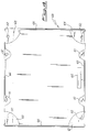
- Fig. 1 is a plan view of the tray element according to the invention, showing the portion destined to form the inside of the whole container;
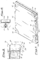
- Fig. 2 is a section according to line II-II of Fig. 1, shown together with another tray element, superimposed to form a container;
- Fig. 3 is a section according to the line III-III of Fig. 1, shown together with another piled up tray element;
- Fig. 4 is a plan view showing the outside of the tray element;
- Fig. 5 is a partial section, expanded scale, according to the line V-V of Fig.1;
- Fig. 6 is a partial section, expanded scale, according to the line VI-VI of Fig. 1; and
- Fig. 7 is a perspective showing the assembled container.
- Making reference to the figures and particularly to Fig. 1, the invention includes an
element 68 rectangular tray shaped, preferably obtained by plastics moulding. - This element includes a
bottom board 50, equipped on one side oflateral walls board 50, with thewalls 1 and 2 placed on the longer sides. Moreover, on the face from which lateral walls rise (called also internal face for the reasons which will become clear when described below) a net of thin and low ribs is foreseen, which are not shown on the drawing not to embroil uselessly the drawing itself. - The wall thickness is not constant and, for our sake, an average thickness s is defined (Fig. 5), corresponding to the lower length of the wall, that is close to the bottom board, which is not involved in modifications made in the rest portion of the wall.
- In the same way, always referring to Fig. 5, an avergae height h is defined corresponding to an element profile which, in the formation of a container, comes in contact with the other element along the whole perimeter of the walls.
- Referring also to Fig. 2, wall 1 foresees, in the center length a straight indentation 11 in the wall thickness and an adjacent
straight projection 12 raising over the profile or average height h of wall 1. The projection 11 and theadjacent indentation 12 have equal length. Furthermore, as all other indentations and projections foreseen by the invention, they have equal height, meaning by this that the length of indentation 11 towards thebase board 50 is equal to the length ofprojection 12 over height h. - The wall foresees futhermore
stiffening ribs 18 facing the straight projection, extending from thebase board 50. - Wall 1 foresees a further
straight indentation 13 and a further straight projection 14, having length equal and lower of the one ofparts 11, 12. - Two pairs of curved indentations are also foreseen on wall 1 and more in particular two
indentations indentations adjacent parts 12, 11 fromparts 13, 14. Curved indentations are obtained performing the wall according to an arch, e.g. a sinusoid. -
Corner indentations flat closing portions bottom board 50, whileindentations flat closing portions bottom board 50.Flat portions - The edge of the corner curved
indentation 15A has aprojection 56 raising over the average profile of the wall and is placed inside the tray element, while the edge of thecurved indentation 15B foresees agroove 55 formed inward the tray element. - The
opposite wall 2 foresees the same elements as wall 1, that iscorner indentations flat closing portions indentations portions straight projections corner indentations curved indentation 55 and acurved projection 56, respectively, andholes - The
curved indentation 25A is illustrated more in detail in the section of Fig. 5 showing also how to position anothertray element 69 to form a container for printed circuit boards. - On the shorter side 3 a
straight projection 31 and astraight indentation 32 are foreseen, adjacent and of equal length, adjacent in their turn to a furtherstraight indentation 33 and to astraight projection 34. The twoparts parts straight projection 34 is without stiffening ribs, whileprojection 31 foresees a series ofstiffening ribs 38. - The other shorter side 4 foresees corresponding straight projections and
indentations projections projection 41 equipped with a series ofstiffening ribs 48. In this case too, each indentation faces a groove of equal length and viceversa. - Referring to Fig. 6 in particular, on the other face, the tray element according to the invention shows two hollow portions and two raised
portions hollow portions edge 66. - The external surface of
board 50 preferably foresees abay 65 obtained by molding, inside which are contained indications, marks, trade marks or other elements which could be directly obtained by molding, or labelled on thebay 65. - Thanks to the proposed configuration and as it can be seen in Fig. 2, two tray elements according to the
invention hinge facing holes 51 of one side, by means of the known connection devices as shown in Fig. 6, or simply with fixing plastic clamps. - Particularly advantageous is the fact that the elements forming the case are identical and therefore they can be obtained with a single mould.
- When not used, several of these trays, can be piled up if oriented in the same direction in order to reduce the storing space, and the single elements are kept in this position thanks to
edge 66 which engages with the straight projections. This is clearly shown also in Fig. 3 where an element 67 dot-drawn has been superimposed toelement 68. - Finally, it is possible to pile also containers formed by two tray elements, due to the presence of part of circle projections, this characteristic is useful for the transport of several printed circuit boards each one in its box. This is clearly shown in the detail of Fig. 5 where over the container 68-69, the
lower element 70 of a further container has been superimposed. - Containers can be fixed among them for transport with plastic clamps passing through
holes 52 and tightened.
Claims (8)
- Tray shaped element, essentially rectangular, for the packing of printed circuit boards, including a bottom board (50) with side walls (1, 2, 3, 4) extending on one side and along the whole perimeter of the bottom board (50),
characterized by the fact that each wall (1, 2, 3, 4) foresees straight indentations (11, 13, 21; 32, 33, 42, 43) in the wall thickness and straight projections (12, 14, 22, 24; 31, 34, 41, 44) from the middle profile or wall height, each indentation on one wall facing a complementary projection on the opposite wall;
and by the provision of two pairs of curved indentations on two opposite walls, the indentations of the first pair (15A, 15B) being performed close to the corners of the wall and providing a flat portion (19A, 19B) essentially forming a part of the bottom board (50), while the indentations of the second pair (17A, 17B) have a flat portion (16A, 16B) parallel to the bottom board, said flat portion being provided with openings (51, 52) to cooperate with the closing means of two coupled elements. - Element according to claim 1, characterized by the provision, on the surface of the bottom board opposite to the one where walls rise, two hollow portions (61, 62) and two raised portions (63, 64) each one formed in correspondence of a corner and diagonally opposed.
- Element according to claim 1 or 2, characterized by the fact that the edge of the two curved indentations (15A, 25B) diagonally opposed of said first pair forms a groove (55) protruding towards the inside of the tray element, while the edge of the other two curved indentations (15B, 25A) form a complementary projection (56) from the middle profile of the wall, placed at the inside the tray element.
- Element according to claim 1, characterized by the fact that said two pair of curved indentations (15A, 15B; 17A, 17B and 25A, 25B; 27A, 27B) are provided on the longer sides of the tray and that between the curved indentations (17A, 17B) of said second pair a projection (12) and one indentation (11) are provided placed adjacent each other and of equal length, and that a further straight indentation (13), one straight projection (14) respectively, separates each curved indentation (17A, 17B) of said second pair from the corresponding corner curved indentation (15A, 15B).
- Element according to claim 1, characterized by the fact that on each shorter side are provided with one projection (31, 41) and an indentation (32, 42) adjacent each other and of equal length, adjacent in their turn to a further straight indentation (33, 43) a straight projection (34,44) respectively.
- Element according to claim 1, characterized by the fact that walls are provided with stiffening ribs (18, 38) facing said straight projections.
- Element according to claim 2, characterized by the fact that said portions (61, 62, 63, 64) have the shape of 90° part of circle.
- Element according to claim 2, characterized by the fact that, on the face opposite to the one where side walls rise, the whole tray peripheral edge is lowered in correspondence of an edge (66).
Applications Claiming Priority (2)
| Application Number | Priority Date | Filing Date | Title |
|---|---|---|---|
| IT2115990U IT219538Z2 (en) | 1990-05-11 | 1990-05-11 | ELEMENT IN THE FORM OF A TRAY FOR THE PACKING OF PRINTED CIRCUIT PLATES |
| IT2115990 | 1990-08-01 |
Publications (2)
| Publication Number | Publication Date |
|---|---|
| EP0456288A1 EP0456288A1 (en) | 1991-11-13 |
| EP0456288B1 true EP0456288B1 (en) | 1995-07-05 |
Family
ID=11177632
Family Applications (1)
| Application Number | Title | Priority Date | Filing Date |
|---|---|---|---|
| EP19910200753 Expired - Lifetime EP0456288B1 (en) | 1990-05-11 | 1991-03-29 | Tray-shaped element for packing of printed circuit boards |
Country Status (3)
| Country | Link |
|---|---|
| EP (1) | EP0456288B1 (en) |
| DE (1) | DE69110973D1 (en) |
| IT (1) | IT219538Z2 (en) |
Family Cites Families (1)
| Publication number | Priority date | Publication date | Assignee | Title |
|---|---|---|---|---|
| US4593813A (en) * | 1985-04-08 | 1986-06-10 | Powel Stephen S | Protective container for assembled printed circuit boards |
-
1990
- 1990-05-11 IT IT2115990U patent/IT219538Z2/en active IP Right Grant
-
1991
- 1991-03-29 EP EP19910200753 patent/EP0456288B1/en not_active Expired - Lifetime
- 1991-03-29 DE DE69110973T patent/DE69110973D1/en not_active Expired - Lifetime
Also Published As
| Publication number | Publication date |
|---|---|
| IT219538Z2 (en) | 1993-03-17 |
| EP0456288A1 (en) | 1991-11-13 |
| IT9021159U1 (en) | 1991-11-11 |
| IT9021159V0 (en) | 1990-05-11 |
| DE69110973D1 (en) | 1995-08-10 |
Similar Documents
| Publication | Publication Date | Title |
|---|---|---|
| US4798305A (en) | Adjustable shipping tray | |
| CA1265478A (en) | Tote box | |
| US6220442B1 (en) | Article of manufacture and method for protecting information-storage devices | |
| AU2004274301A1 (en) | Article storage case | |
| EP0404520B1 (en) | Collapsible container for storage and transport of manufactured articles | |
| US3870188A (en) | Tray or crate | |
| JPH07257682A (en) | Parts tray | |
| IT9053070U1 (en) | CARDBOARD BOX FOR DETERIORABLE PRODUCTS. | |
| US5303820A (en) | Packaging for protecting printed circuit board and other products | |
| FR2629793B1 (en) | MODULAR PACKAGING, CAPABLE OF BEING STACKED WITH PACKAGING OF THE SAME TYPE, BUT DIFFERENT IN VOLUME TO FORM A PALLETIZABLE LOT | |
| US4143763A (en) | Collapsible shipping container for circuit boards | |
| US4711355A (en) | Stackable box | |
| EP0456288A1 (en) | Tray-shaped element for packing of printed circuit boards | |
| US3285491A (en) | Molded carton | |
| EP0085559A2 (en) | Packaging containers | |
| GB2270068A (en) | Box container for rigid sheet bodies | |
| EP0614433B1 (en) | Nestable container | |
| JPH0729640Y2 (en) | Wafer container bottom cushion | |
| JPH0356508Y2 (en) | ||
| WO1995008485A1 (en) | Integrally moulded double corner protector | |
| KR200250096Y1 (en) | A case for food keeping | |
| JP3677439B2 (en) | Folding container | |
| JPS6313159Y2 (en) | ||
| JPH047109Y2 (en) | ||
| JPH0539087Y2 (en) |
Legal Events
| Date | Code | Title | Description |
|---|---|---|---|
| PUAI | Public reference made under article 153(3) epc to a published international application that has entered the european phase |
Free format text: ORIGINAL CODE: 0009012 |
|
| AK | Designated contracting states |
Kind code of ref document: A1 Designated state(s): DE ES FR GB SE |
|
| 17P | Request for examination filed |
Effective date: 19920414 |
|
| 17Q | First examination report despatched |
Effective date: 19940722 |
|
| GRAA | (expected) grant |
Free format text: ORIGINAL CODE: 0009210 |
|
| AK | Designated contracting states |
Kind code of ref document: B1 Designated state(s): DE ES FR GB SE |
|
| PG25 | Lapsed in a contracting state [announced via postgrant information from national office to epo] |
Ref country code: FR Effective date: 19950705 Ref country code: ES Free format text: THE PATENT HAS BEEN ANNULLED BY A DECISION OF A NATIONAL AUTHORITY Effective date: 19950705 |
|
| REF | Corresponds to: |
Ref document number: 69110973 Country of ref document: DE Date of ref document: 19950810 |
|
| PG25 | Lapsed in a contracting state [announced via postgrant information from national office to epo] |
Ref country code: SE Effective date: 19951005 |
|
| PG25 | Lapsed in a contracting state [announced via postgrant information from national office to epo] |
Ref country code: DE Effective date: 19951006 |
|
| EN | Fr: translation not filed | ||
| PLBE | No opposition filed within time limit |
Free format text: ORIGINAL CODE: 0009261 |
|
| STAA | Information on the status of an ep patent application or granted ep patent |
Free format text: STATUS: NO OPPOSITION FILED WITHIN TIME LIMIT |
|
| 26N | No opposition filed | ||
| PGFP | Annual fee paid to national office [announced via postgrant information from national office to epo] |
Ref country code: GB Payment date: 19980320 Year of fee payment: 8 |
|
| PG25 | Lapsed in a contracting state [announced via postgrant information from national office to epo] |
Ref country code: GB Free format text: LAPSE BECAUSE OF NON-PAYMENT OF DUE FEES Effective date: 19990329 |
|
| GBPC | Gb: european patent ceased through non-payment of renewal fee |
Effective date: 19990329 |