EP0455868B1 - Low-bed trailer suspension system - Google Patents
Low-bed trailer suspension system Download PDFInfo
- Publication number
- EP0455868B1 EP0455868B1 EP90122887A EP90122887A EP0455868B1 EP 0455868 B1 EP0455868 B1 EP 0455868B1 EP 90122887 A EP90122887 A EP 90122887A EP 90122887 A EP90122887 A EP 90122887A EP 0455868 B1 EP0455868 B1 EP 0455868B1
- Authority
- EP
- European Patent Office
- Prior art keywords
- bushing
- pivot brackets
- web
- trailing arm
- opening
- Prior art date
- Legal status (The legal status is an assumption and is not a legal conclusion. Google has not performed a legal analysis and makes no representation as to the accuracy of the status listed.)
- Expired - Lifetime
Links
- 239000000725 suspension Substances 0.000 title claims description 22
- 239000006096 absorbing agent Substances 0.000 description 1
- 230000000712 assembly Effects 0.000 description 1
- 238000000429 assembly Methods 0.000 description 1
- 230000000295 complement effect Effects 0.000 description 1
- 238000010276 construction Methods 0.000 description 1
- 230000035939 shock Effects 0.000 description 1
Images




Classifications
-
- B—PERFORMING OPERATIONS; TRANSPORTING
- B60—VEHICLES IN GENERAL
- B60G—VEHICLE SUSPENSION ARRANGEMENTS
- B60G7/00—Pivoted suspension arms; Accessories thereof
- B60G7/02—Attaching arms to sprung part of vehicle
-
- B—PERFORMING OPERATIONS; TRANSPORTING
- B60—VEHICLES IN GENERAL
- B60G—VEHICLE SUSPENSION ARRANGEMENTS
- B60G2204/00—Indexing codes related to suspensions per se or to auxiliary parts
- B60G2204/40—Auxiliary suspension parts; Adjustment of suspensions
- B60G2204/43—Fittings, brackets or knuckles
- B60G2204/4306—Bracket or knuckle for rigid axles, e.g. for clamping
-
- F—MECHANICAL ENGINEERING; LIGHTING; HEATING; WEAPONS; BLASTING
- F16—ENGINEERING ELEMENTS AND UNITS; GENERAL MEASURES FOR PRODUCING AND MAINTAINING EFFECTIVE FUNCTIONING OF MACHINES OR INSTALLATIONS; THERMAL INSULATION IN GENERAL
- F16B—DEVICES FOR FASTENING OR SECURING CONSTRUCTIONAL ELEMENTS OR MACHINE PARTS TOGETHER, e.g. NAILS, BOLTS, CIRCLIPS, CLAMPS, CLIPS OR WEDGES; JOINTS OR JOINTING
- F16B2200/00—Constructional details of connections not covered for in other groups of this subclass
- F16B2200/40—Clamping arrangements where clamping parts are received in recesses of elements to be connected
- F16B2200/403—Threaded clamping parts
-
- F—MECHANICAL ENGINEERING; LIGHTING; HEATING; WEAPONS; BLASTING
- F16—ENGINEERING ELEMENTS AND UNITS; GENERAL MEASURES FOR PRODUCING AND MAINTAINING EFFECTIVE FUNCTIONING OF MACHINES OR INSTALLATIONS; THERMAL INSULATION IN GENERAL
- F16B—DEVICES FOR FASTENING OR SECURING CONSTRUCTIONAL ELEMENTS OR MACHINE PARTS TOGETHER, e.g. NAILS, BOLTS, CIRCLIPS, CLAMPS, CLIPS OR WEDGES; JOINTS OR JOINTING
- F16B2200/00—Constructional details of connections not covered for in other groups of this subclass
- F16B2200/50—Flanged connections
- F16B2200/506—Flanged connections bolted or riveted
-
- Y—GENERAL TAGGING OF NEW TECHNOLOGICAL DEVELOPMENTS; GENERAL TAGGING OF CROSS-SECTIONAL TECHNOLOGIES SPANNING OVER SEVERAL SECTIONS OF THE IPC; TECHNICAL SUBJECTS COVERED BY FORMER USPC CROSS-REFERENCE ART COLLECTIONS [XRACs] AND DIGESTS
- Y10—TECHNICAL SUBJECTS COVERED BY FORMER USPC
- Y10T—TECHNICAL SUBJECTS COVERED BY FORMER US CLASSIFICATION
- Y10T403/00—Joints and connections
- Y10T403/70—Interfitted members
- Y10T403/7047—Radially interposed shim or bushing
- Y10T403/7049—Biased by distinct radially acting means
Definitions
- This invention relates in general to new and useful improvements in suspension systems for vehicles, and more particularly to a suspension system for a low-bed type trailer.
- the suspension system requires brackets which are bolted or welded to the underside of the main beam of the trailer frame. This not only complicates the mounting of a supporting axle, but also requires that the axle be located further rearwardly of the offset of the trailer frame than is desired.
- the customary trailing arm is directly mounted on a bushing assembly which is carried by the web of the frame beam, thereby permitting the forward axle of a pair of axles to be mounted closely adjacent the offset in the beam and thus moving the forward axle forward a considerable distance.
- This mounting also permits the rear axle to be moved forwardly accordingly and thereby moves the suspension for the trailer forward with respect to that portion of the trailer receiving the load.
- an opening is formed in the web of the frame beam, preferably in the offset portion of the beam, and there is secured to opposite sides of the web pivot brackets which mount a bushing assembly including a bushing core through which either a bolt or a torsion bar may pass to secure the trailing arm in position for limited pivotal movement.
- an elongated opening may be formed in at least one side of the trailer frame and the axle initially mounted after which at least one of the trailing arms is adjusted back or forth as required to make the axle square with respect to the trailer frame.
- FIG. 1 wherein there is illustrated a rear portion of a low-bed trailer, the trailer being generally identified by the numeral 10.
- Low-bed trailers conventionally include a frame formed of two main frame members in the form of I-beams.
- Such an I-beam generally identified by the numeral 12, will include at least a low intermediate portion or well 14 and a high suspension mounting rear portion 16, the portions 14 and 16 being generally parallel to one another and being joined by an intermediate upwardly and rearwardly sloping portion 18.
- Each I-beam frame member 12 includes an upper flange 20, a lower flange 22 and a web 24.
- each of the I-beams 12 is provided with a depending mounting bracket 30 which is suitably bolted or welded to the underside of the flange 22.
- Each bracket 30 carries a pivot 32 normally in the form of a bolt and nut arrangement.
- Carried by the pivot 32 is a trailing arm or equalizing beam 34.
- At the rear end of the trailing arm 34 and extending between the trailing arm 34 and the underside of the I-beam 12 is an air spring 36.
- the axle 28 is mounted on an intermediate part of the trailing arm 34 utilizing a clamping assembly 38 which incorporates two U-bolts 40.
- the clamping assembly 38 also provides for the mounting of a shock absorber 42 which has its upper end (not shown) connected to the trailer 10.
- the mounting bracket 30 can have a forward position only behind the intermediate offset portion 18 of the I-beam 12. This results in not only the front axle 26, but also the rear axle 28 being further rearward than desired with respect to the well or load receiving portion of the trailer.
- the axle 26 is carried by a pair of equalizing beams or trailing arms 44 which are carried by a bushing assembly, generally identified by the numeral 46, which is directly mounted on the web 24 of the intermediate portion 18 as shown in FIG. 1.
- FIG. 2 wherein it will be seen that the web 24 of the intermediate portion 18 of the I-beam 12 is provided with an opening 48 which is elongated in the fore and aft direction.
- Line 50 indicates the center of the opening 48 while lines 52 and 54 indicate the centers of bores for forming the opening 48.
- the bushing assembly 46 is to be mounted on the web 24 utilizing four mounting bolts as will be described hereinafter. These mounting bolts pass through bolt holes which may either be drilled after the bushing assembly has been clamped onto the web 24, or, as shown in FIG. 3, holes 56, which are also elongated in the fore and aft direction, may be preformed in the web 24. Each hole 56 would also have longitudinally spaced drill centers 58 and 60.
- the bushing assembly 46 includes an outer pivot bracket 62 and an inner pivot bracket 64.
- the pivot brackets 62 and 64 are of identical construction except for being left and right handed. Accordingly, only the pivot bracket 64, which is illustrated in FIG. 5, will be specifically described here.
- the pivot bracket 64 includes a mounting plate 66 which includes a half circular forward part 68 and a rectangular rear part 70.
- the mounting plate 66 is provided with a large bore 72 therethrough in which there is seated one end of a collar 74.
- the collar 74 is reinforced by three upstanding ribs 76 and a U-shaped cross sectional member 78.
- the U-shaped cross sectional member includes two upstanding flanges 80 joined together by a web 82.
- the web 82 is discontinued adjacent the collar 74 with the web 82 functioning as a lateral guide for engaging the trailing arm 44 in a manner to be described hereinafter.
- the sleeve 84 carries an elastomeric bushing 88 which is preferably bonded to the interior of the sleeve 84 and which, in turn, carries a bushing core 90 which is tubular and which is also bonded to the bushing 88.
- axle 26 will be supported by a pair of the trailing arms or equalizing beams 44 and that each trailing arm 44 will be mounted in the same manner described above. It may be that the opening for the sleeve 84 formed in the other I-beam 12 is circular although it is preferred that it would be elongated in the same manner as the opening 48. By shifting at least one of the bushing assemblies relative to the web 24, the axle 26 may be accurately squared with respect to the trailer frame 12.
- the outer pivot bracket 62 will be welded to the web 24 in several places such as at 98 in FIG. 4. This assures that when the bushing assembly 46 is disassembled for any reason, it may be accurately assembled once again.
- the pivot brackets 62, 64 may be clamped in place, the axle position adjusted, and then the holes equivalent to the holes 56 drilled. This will eliminate the elongation of the holes 56. Even with this arrangement, the pivot bracket 62 would be preferably welded to the web 24 as described above.
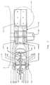
- FIG. 7 wherein it will be seen that there is illustrated the overall configuration of a typical trailing arm or equalizing beam 44.
- the trailing arm 44 has a forward portion 100 in the form of a yoke including two arms 102.
- the arms 102 have projecting opposed bosses 104 having bores 106 therethrough.
- the spacing of the opposed faces of the bosses 104 corresponds substantially to the length of the bushing core 90.
- axle 26 will overlie the trailing arm 44 and will be fixedly secured thereto by way of a clamp assembly 112 which includes a pair of U-bolts 114.
- the rear end portion of the trailing arm 44 will include a lower mounting plate 115 to which the base of an air spring 116 may be secured.
- the top of the air spring 116 will be suitably secured to the flange 22.
- FIG. 8 wherein there is schematically illustrated the mounting of a pair of the trailing arms 44 wherein the trailing arms are joined together by a torsion bar 118 in lieu of the bolts 108.
- the torsion bar 118 may be provided with a shoulder 120 for engaging an inner one of the arms 102 and a threaded end portion and nut 122 for engaging the outer arm 102 to thus clamp the arms together as described above with respect to FIG. 7.
- the bushing assembly includes one bushing 132 for each of the pivot brackets 62, 64 with each bushing 132 having a pressed fit within the respective collar 74, the sleeve 84 being eliminated.
- Each bushing is provided with a relatively large diameter bushing core 134 which is bonded to the respective bushing 132 and will have a bore 136 therethrough for receiving either the bolt 108 or the torsion bar 112.
- each bushing 132 is of a length shorter than the associated bushing core 134 and will have its ends spaced from the ends of the bushing core 134.
- the bushing core 134 will be of a diameter generally equal to the diameter or height of the hole 48 and abutting end portions of the two bushing cores 134 will be received in the hole 48 in the same manner as did occur by the sleeve 84. It will be seen that the opposed ends of the two bushings 132 may be spaced apart to clear the web 24.
- a shim 138 can be provided between one or both of the brackets 62, 64 and the web 24 to assure proper abutment of the end portions of the two bushing cores 134 without stress on the bushings 132.
- Each pivot bracket 62, 64 has V-shaped notches 140 at lateral edges of the rear portion 70.
- alignment blocks 142 complementary in shape to the notches 140 are welded to the web 24 as at 144 to engage the notches and thus maintain the position of the brackets 62, 64 at the point of axle alignment. It will be apparent that with this structure, the bushing assembly 130 can be easily removed and replaced without having to realign the axle.
- the bushing assembly 130 is preferred over the bushing assembly formed of the sleeve 84, the bushing 88 and the bushing core 90 in that the bushing of this assembly together with the bushing cores, may be readily replaced.
Landscapes
- Engineering & Computer Science (AREA)
- Mechanical Engineering (AREA)
- Vehicle Body Suspensions (AREA)
Description
- This invention relates in general to new and useful improvements in suspension systems for vehicles, and more particularly to a suspension system for a low-bed type trailer.
- In the customary suspension system for trailers, particularly heavy duty trailers of the low-bed type, the suspension system requires brackets which are bolted or welded to the underside of the main beam of the trailer frame. This not only complicates the mounting of a supporting axle, but also requires that the axle be located further rearwardly of the offset of the trailer frame than is desired.
- In accordance with this invention and as defined in
independent claim 1, the customary trailing arm is directly mounted on a bushing assembly which is carried by the web of the frame beam, thereby permitting the forward axle of a pair of axles to be mounted closely adjacent the offset in the beam and thus moving the forward axle forward a considerable distance. This mounting also permits the rear axle to be moved forwardly accordingly and thereby moves the suspension for the trailer forward with respect to that portion of the trailer receiving the load. - In accordance with this invention, an opening is formed in the web of the frame beam, preferably in the offset portion of the beam, and there is secured to opposite sides of the web pivot brackets which mount a bushing assembly including a bushing core through which either a bolt or a torsion bar may pass to secure the trailing arm in position for limited pivotal movement.
- In one preferred aspect of this suspension system, an elongated opening may be formed in at least one side of the trailer frame and the axle initially mounted after which at least one of the trailing arms is adjusted back or forth as required to make the axle square with respect to the trailer frame.
- With the above and other objects in view that will hereinafter appear, the nature of the invention will be more clearly understood by reference to the following detailed description, the appended claims, and the several views illustrated in the accompanying drawings.
-
- FIG. 1 is a fragmentary side elevational view of a low-bed trailer and shows the suspension system for such trailer in accordance with this invention;
- FIG. 2 is a fragmentary elevational view of the trailer frame without the suspension system and shows the position of the elongated opening therethrough;
- FIG. 3 is a fragmentary elevational view similar to FIG. 2 but additionally shows elongated bolt holes for adjustably mounting pivot brackets of the suspension system;
- FIG. 4 is a transverse vertical sectional view taken through the bushing assembly and shows the specific details thereof;
- FIG. 5 is an elevational view taken generally along the line 5-5 of FIG. 4 and shows the details of the bushing assembly;
- FIG. 6 is an exploded vertical sectional view taken through the bushing assembly along the same plane as FIG. 4;
- FIG. 7 is a horizontal sectional view taken generally along the line 7-7 of FIG. 4 and shows the overall mounting of an axle in accordance with this invention;
- FIG. 8 is a fragmentary schematic plan view showing two trailing arms joined by a torsion bar in accordance with this invention; and
- FIG. 9 is an exploded vertical sectional view similar to FIG. 6 showing a modified bushing assembly.
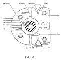
- FIG. 10 is an elevational view similar to FIG. 5 showing the modified bushing assembly of FIG. 9.
- Referring now to the drawings in detail, reference is first made to FIG. 1 wherein there is illustrated a rear portion of a low-bed trailer, the trailer being generally identified by the
numeral 10. Low-bed trailers conventionally include a frame formed of two main frame members in the form of I-beams. Such an I-beam, generally identified by thenumeral 12, will include at least a low intermediate portion or well 14 and a high suspension mountingrear portion 16, theportions portion 18. Each I-beam frame member 12 includes anupper flange 20, alower flange 22 and aweb 24. - In the illustrated suspension for the
trailer 10, there is afront axle 26 and arear axle 28. Therear axle 28 is mounted in the customary manner and thus will be described first. Each of the I-beams 12 is provided with a dependingmounting bracket 30 which is suitably bolted or welded to the underside of theflange 22. Eachbracket 30 carries apivot 32 normally in the form of a bolt and nut arrangement. Carried by thepivot 32 is a trailing arm or equalizingbeam 34. At the rear end of thetrailing arm 34 and extending between thetrailing arm 34 and the underside of the I-beam 12 is anair spring 36. - The
axle 28 is mounted on an intermediate part of the trailingarm 34 utilizing aclamping assembly 38 which incorporates twoU-bolts 40. Theclamping assembly 38 also provides for the mounting of ashock absorber 42 which has its upper end (not shown) connected to thetrailer 10. - It will be apparent that when the
conventional mounting bracket 30 is utilized in the mounting of thefront axle 26, themounting bracket 30 can have a forward position only behind theintermediate offset portion 18 of the I-beam 12. This results in not only thefront axle 26, but also therear axle 28 being further rearward than desired with respect to the well or load receiving portion of the trailer. - In accordance with this invention, the
axle 26 is carried by a pair of equalizing beams or trailingarms 44 which are carried by a bushing assembly, generally identified by thenumeral 46, which is directly mounted on theweb 24 of theintermediate portion 18 as shown in FIG. 1. - Reference is now made to FIG. 2 wherein it will be seen that the
web 24 of theintermediate portion 18 of the I-beam 12 is provided with an opening 48 which is elongated in the fore and aft direction.Line 50 indicates the center of theopening 48 whilelines opening 48. - It is to be understood that the
bushing assembly 46 is to be mounted on theweb 24 utilizing four mounting bolts as will be described hereinafter. These mounting bolts pass through bolt holes which may either be drilled after the bushing assembly has been clamped onto theweb 24, or, as shown in FIG. 3,holes 56, which are also elongated in the fore and aft direction, may be preformed in theweb 24. Eachhole 56 would also have longitudinally spaceddrill centers 58 and 60. - Reference is now made to FIG. 6 wherein the details of the
bushing assembly 46 are specifically illustrated. Thebushing assembly 46 includes anouter pivot bracket 62 and aninner pivot bracket 64. Thepivot brackets pivot bracket 64, which is illustrated in FIG. 5, will be specifically described here. Thepivot bracket 64 includes amounting plate 66 which includes a half circularforward part 68 and a rectangularrear part 70. Themounting plate 66 is provided with alarge bore 72 therethrough in which there is seated one end of acollar 74. Thecollar 74 is reinforced by threeupstanding ribs 76 and a U-shaped crosssectional member 78. The U-shaped cross sectional member includes twoupstanding flanges 80 joined together by aweb 82. Theweb 82 is discontinued adjacent thecollar 74 with theweb 82 functioning as a lateral guide for engaging thetrailing arm 44 in a manner to be described hereinafter. - There is an elongated
tubular sleeve 84 which telescopes in a tight fit within thecollars 74 with thesleeve 84 being welded to thecollar 74 of thepivot bracket 64 as at 86. - The
sleeve 84 carries anelastomeric bushing 88 which is preferably bonded to the interior of thesleeve 84 and which, in turn, carries abushing core 90 which is tubular and which is also bonded to the bushing 88. - As will be apparent from FIG. 4, when the bushing assembly is mounted on the
web 24, thesleeve 84 will pass through the opening 48 in theweb 24. When theweb 24 is provided with theelongated holes 56,bores 92 formed in themounting plates 66 will be aligned with each other and with theholes 56 so thatbolts 94 may be passed through thealigned bores 92 andholes 56 and receivenuts 96. - At this time it is pointed out that the
axle 26 will be supported by a pair of the trailing arms or equalizingbeams 44 and that eachtrailing arm 44 will be mounted in the same manner described above. It may be that the opening for thesleeve 84 formed in the other I-beam 12 is circular although it is preferred that it would be elongated in the same manner as the opening 48. By shifting at least one of the bushing assemblies relative to theweb 24, theaxle 26 may be accurately squared with respect to thetrailer frame 12. - After the
bushing assembly 46 has been assembled to mount theaxle 26 in its proper position, theouter pivot bracket 62 will be welded to theweb 24 in several places such as at 98 in FIG. 4. This assures that when thebushing assembly 46 is disassembled for any reason, it may be accurately assembled once again. - On the other hand, if the
web 24 is not provided with theholes 56, thepivot brackets holes 56 drilled. This will eliminate the elongation of theholes 56. Even with this arrangement, thepivot bracket 62 would be preferably welded to theweb 24 as described above. - Reference is now made to FIG. 7 wherein it will be seen that there is illustrated the overall configuration of a typical trailing arm or equalizing
beam 44. It will be seen that the trailingarm 44 has aforward portion 100 in the form of a yoke including twoarms 102. Thearms 102 have projecting opposedbosses 104 havingbores 106 therethrough. The spacing of the opposed faces of thebosses 104 corresponds substantially to the length of thebushing core 90. Thus when abolt 108 is passed through the alignedholes 106 and thebushing core 90, and anut 110 is applied to thebolt 108 so as to draw thearms 102 together, the ends of thebushing core 90 will be tightly clamped by thebosses 104 so that as the trailingarm 44 pivots, thebushing core 90 will pivot with it against the resistance of thebushing 88. - As is clearly shown in Figs. 1 and 7, the
axle 26 will overlie the trailingarm 44 and will be fixedly secured thereto by way of aclamp assembly 112 which includes a pair ofU-bolts 114. - Further, the rear end portion of the trailing
arm 44 will include alower mounting plate 115 to which the base of anair spring 116 may be secured. The top of theair spring 116 will be suitably secured to theflange 22. - Reference is now made to FIG. 8 wherein there is schematically illustrated the mounting of a pair of the trailing
arms 44 wherein the trailing arms are joined together by atorsion bar 118 in lieu of thebolts 108. If desired, thetorsion bar 118 may be provided with ashoulder 120 for engaging an inner one of thearms 102 and a threaded end portion andnut 122 for engaging theouter arm 102 to thus clamp the arms together as described above with respect to FIG. 7. - Reference is now made to an improved bushing assembly, shown in FIGS. 9 and 10 and generally identified by the numeral 130. The bushing assembly includes one
bushing 132 for each of thepivot brackets bushing 132 having a pressed fit within therespective collar 74, thesleeve 84 being eliminated. - Each bushing is provided with a relatively large
diameter bushing core 134 which is bonded to therespective bushing 132 and will have abore 136 therethrough for receiving either thebolt 108 or thetorsion bar 112. - It is to be noted that each
bushing 132 is of a length shorter than the associatedbushing core 134 and will have its ends spaced from the ends of thebushing core 134. Thebushing core 134 will be of a diameter generally equal to the diameter or height of thehole 48 and abutting end portions of the twobushing cores 134 will be received in thehole 48 in the same manner as did occur by thesleeve 84. It will be seen that the opposed ends of the twobushings 132 may be spaced apart to clear theweb 24. Ashim 138 can be provided between one or both of thebrackets web 24 to assure proper abutment of the end portions of the twobushing cores 134 without stress on thebushings 132. - Each
pivot bracket notches 140 at lateral edges of therear portion 70. After thebushing assembly 130 is mounted to theweb 24 and properly aligned as hereinabove described, alignment blocks 142, complementary in shape to thenotches 140 are welded to theweb 24 as at 144 to engage the notches and thus maintain the position of thebrackets bushing assembly 130 can be easily removed and replaced without having to realign the axle. - The
bushing assembly 130 is preferred over the bushing assembly formed of thesleeve 84, thebushing 88 and thebushing core 90 in that the bushing of this assembly together with the bushing cores, may be readily replaced. - Although only several preferred embodiments of the pivotal mounting of the trailing arms or equalizing beams have been specifically illustrated and described herein, it is to be understood that variations may be made therein without departing from the scope of the invention as defined by the appended claims.
Claims (24)
- A trailing arm suspension for a vehicle having a frame beam (12) including a web (24), the suspension characterized by inner and outer pivot brackets (64, 62) adapted to be secured to opposite sides of said web (24) in alignment with each other and with an opening (48) in said web (24), a bushing (46) in said pivot brackets (64, 62), a bushing core (90) carried by said bushing (88) and extending in opposite directions out of said pivot brackets (64, 62), fastening means extending through said bushing core (90), a trailing arm (44) including a front portion (100) in the form of a yoke including two spaced arms (102), said arms opposing opposite ends of said bushing core (90) and being pivotally mounted thereto by said fastening means (108, 110).
- A trailing arm suspension according to claim 1 wherein said bushing includes separate bushing members (132) pressed into each of said pivot brackets (62, 64), and said bushing core being formed in two parts (134) with each part being bonded to a respective bushing member (132), said bushing core parts (134) abutting each other within said opening.
- A trailing arm suspension according to claim 1 or 2, wherein said bushing core (90) extends beyond said bushing (88) and is clamped by said yoke arms (102) to pivot with said trailing arm (44).
- A trailing arm suspension according to one of claims 1 to 3 wherein each of said pivot brackets (62, 64) include a mounting face (66) engaging said web (24) and a collar (74) projecting in an opposite direction from said mounting face (66), said bushing parts (134) each being separately removably mounted in each of said collars (74).
- A trailing arm suspension according to one of claims 1 to 4 wherein said pivot brackets (62, 64) have lateral guides (82) for engaging said yoke arms (102) to restrict lateral movement of said trailing arm (44).
- A trailing arm suspension according to one of claims 1 to 5 wherein said frame beam (12) also includes flanges (20, 22) carried by said web (24), and said bushing core (90) is of a length generally corresponding to widths of said flanges (20, 22) whereby said yoke (100) clears said flanges (20, 22).
- A trailing arm suspension according to one of claims 1 to 6 wherein said fastening means is in the form of a boltlike member (108).
- A trailing arm suspension according to one of claims 1 to 6 wherein said fastening means is in the form of a torsion bar (118).
- In a vehicle having a vehicle frame beam (12) with a forward lower portion (14), a rear upper portion (16) and an upwardly and rearwardly sloping intermediate portion (18), an opening (48) formed in said intermediate portion (18), and a trailing arm suspension according to one of claims 1 to 8 mounted to said frame (12) in said opening (48) extending rearwardly beneath said rear upper portion (16).
- A vehicle according to claim 9, wherein said vehicle frame is a low bed trailer frame.
- A vehicle according to claim 9 or 10 wherein said opening (48) is fore and aft elongated to permit adjusted positioning of said trailing arm (44), and fasteners pass through holes (56) formed in said web (24) after said pivot brackets (62, 64) have been positioned relative to said opening (48).
- A vehicle according to one of claims 9 or 10 wherein said opening (48) is fore and aft elongated to permit adjusted positioning of said trailing arm (44), and one of said pivot brackets (62, 64) is welded to said web (24) after said pivot brackets (62, 64) have been positioned in said opening (48).
- A vehicle according to one of claims 9 to 12
wherein there are two of said frame beams (12) in transverse spaced relation, one of said trailing arms (44) is adapted to be carried by each of said frame beams (12), a wheel axle (26) carried by said trailing arms (44), and at least one of said openings (48) is fore and aft elongated to permit adjusted positioning of at least one of said trailing arms (44) to align said axle (26). - A vehicle according to claim 13 wherein said fasteners (108, 110) pass through holes (56) formed in the web (24) having said elongated opening (48) after said axle position has been adjusted.
- A vehicle according to claim 13 or 14, wherein one of said pivot brackets (62, 64) associated with said web (24) having said elongated opening (48) is welded to said web (24) after said axle position has been adjusted.
- A vehicle according to one of claims 9 to 15
wherein a sleeve (84) extends through said opening (48) and into each of said pivot brackets (62, 64), and said bushing (88) is received in said sleeve (84) with said bushing core (90) projecting beyond ends of said sleeve (84). - A bushing assembly characterised in that said assembly is for mounting a trailing arm (44) on a web (24) of a vehicle frame beam (12) relative to an opening (48) through such web (24), said bushing assembly comprising inner and outer pivot brackets (64, 62) securable to opposite sides of such web (24) in alignment with such opening (48), a bushing (88) within said pivot brackets (62, 64), a bushing core (90) extending through said bushing (88), said bushing core (90) having a through bore for receiving fastening means (108, 118) for securing a trailing arm yoke (100) to said bushing assembly (46), said bushing core (90) extending beyond both said bushing (88) and said pivot brackets (62, 64).
- A bushing assembly according to claim 17 wherein said bushing includes separate bushing members (132) pressed into each of said pivot brackets (62, 64) and said bushing core being formed in two parts (134) with each part (134) being bonded to a respective bushing member (132), said bushing core parts (134) abutting each other.
- A bushing assembly according to claim 18 wherein each of said pivot brackets (62, 64) include a mounting face (66) for engaging said web and a collar (74) projecting in an opposite direction from said mounting face, said bushing parts (132) each being separately removable pressed in each of said collars.
- A bushing assembly according to claim 17 wherein said bushing (88) is received in a sleeve (84) received in said pivot brackets (62, 64) with said bushing core (90) extending beyond said pivot brackets.
- A bushing assembly according to claim 20 wherein said sleeve (84) is fixed to one of said pivot brackets (62, 64) and slidable within the other of said pivot brackets (62, 64).
- A bushing assembly according to claim 20 wherein each of said pivot brackets (62, 64) includes a mounting face (66) and a collar (74) projecting in an opposite direction from said mounting face (66), and said sleeve (84) has opposite ends telescoped into respective collars (74).
- A bushing assembly according to claim 22 wherein said sleeve (84) is fixedly secured to one of said collars (74) and slidable in the other of said collars (74).
- A bushing assembly according to claim 16 wherein said pivot brackets (62, 64) have oppositely facing lateral guides (82) for restricting lateral movement of an associated yoke (100).
Applications Claiming Priority (2)
| Application Number | Priority Date | Filing Date | Title |
|---|---|---|---|
| US519164 | 1990-05-04 | ||
| US07/519,164 US4991872A (en) | 1990-05-04 | 1990-05-04 | Low-bed trailer suspension system |
Publications (3)
| Publication Number | Publication Date |
|---|---|
| EP0455868A2 EP0455868A2 (en) | 1991-11-13 |
| EP0455868A3 EP0455868A3 (en) | 1992-07-08 |
| EP0455868B1 true EP0455868B1 (en) | 1994-09-07 |
Family
ID=24067139
Family Applications (1)
| Application Number | Title | Priority Date | Filing Date |
|---|---|---|---|
| EP90122887A Expired - Lifetime EP0455868B1 (en) | 1990-05-04 | 1990-11-29 | Low-bed trailer suspension system |
Country Status (6)
| Country | Link |
|---|---|
| US (1) | US4991872A (en) |
| EP (1) | EP0455868B1 (en) |
| AU (1) | AU629416B2 (en) |
| CA (1) | CA2029996A1 (en) |
| DE (1) | DE69012314T2 (en) |
| DK (1) | DK0455868T3 (en) |
Families Citing this family (14)
| Publication number | Priority date | Publication date | Assignee | Title |
|---|---|---|---|---|
| DE4123778C2 (en) * | 1990-10-01 | 1996-03-14 | Krauss Maffei Ag | Caterpillar |
| US6227554B1 (en) * | 1999-06-30 | 2001-05-08 | Reyco Industries, Inc. | Adjustment mechanism for alignment of a pivot bushing, trailing beam and axle |
| DE10009920A1 (en) * | 2000-03-01 | 2001-09-06 | Bayerische Motoren Werke Ag | Rear wheel suspension for motor vehicles has transverse control arm holder fastened to axle bearer or chassis, with arm connection for forked arm end |
| US6447073B1 (en) | 2001-05-02 | 2002-09-10 | Bernhardt P. Goettker | Torsion axle having a selectively replaceable insert assembly |
| CA2446413C (en) | 2001-05-04 | 2010-06-22 | The Holland Group, Inc. | Trailing beam suspension with alignment adjustment |
| DE10136821A1 (en) * | 2001-07-27 | 2003-02-06 | Bayerische Motoren Werke Ag | Metal support part, in particular vehicle axle support part, with a welded-on bearing bush |
| AU2003208927A1 (en) * | 2002-02-01 | 2003-09-02 | The Holland Group, Inc. | Trailing arm suspension with optimized i-beam |
| US7178817B1 (en) | 2002-11-01 | 2007-02-20 | Monaco Coach Corporation | Trailing arm suspension system |
| SE530641C2 (en) * | 2005-12-19 | 2008-07-29 | Volvo Lastvagnar Ab | Mounting device for mounting on a vehicle frame |
| US9096108B2 (en) | 2011-05-12 | 2015-08-04 | Vdl Weweler B.V. | Wheel axle suspension |
| US8888135B1 (en) * | 2013-06-25 | 2014-11-18 | Miles A. Reitnouer | Clamp attachment of suspension hanger to aluminum flatbed frame |
| US10780924B2 (en) | 2017-04-05 | 2020-09-22 | Fontaine Commercial Trailer, Inc. | Bogie for a lowboy trailer |
| US11873026B2 (en) | 2020-02-06 | 2024-01-16 | Fontaine Commercial Trailer, Inc. | Bogie for a lowboy trailer |
| CN115749320B (en) * | 2022-11-22 | 2025-04-29 | 滁州金诚金属制品有限公司 | I-beam suspension adapter |
Family Cites Families (14)
| Publication number | Priority date | Publication date | Assignee | Title |
|---|---|---|---|---|
| US313722A (en) * | 1885-03-10 | Knob attachment | ||
| CH203574A (en) * | 1937-05-10 | 1939-03-15 | Daimler Benz Ag | Device for supporting a vehicle upper part on the wheels, in particular for motor vehicles. |
| US2981537A (en) * | 1959-12-14 | 1961-04-25 | Gen Motors Corp | Self-damping torsilastic suspension |
| US3482854A (en) * | 1968-03-25 | 1969-12-09 | Neway Equipment Co | Suspension structure for automotive vehicles |
| AU3076371A (en) * | 1971-07-05 | 1972-04-13 | Abram Kalpakoff Daniel | Improved tandem axle and suspension for trailers |
| US3801086A (en) * | 1972-08-23 | 1974-04-02 | J Raidel | Vehicle air spring suspension assembly |
| US3960388A (en) * | 1975-03-27 | 1976-06-01 | Lear Siegler, Inc. | Vehicle suspension system and alignment mechanism therefor |
| US4371190A (en) * | 1980-01-28 | 1983-02-01 | Turner Quick-Lift Corporation | Axle suspension system |
| US4504080A (en) * | 1983-05-16 | 1985-03-12 | Turner Quick-Lift Corporation | Leaf spring lift axle suspension system |
| FR2548972B1 (en) * | 1983-07-11 | 1987-08-14 | Peugeot | CONNECTION DEVICE WITH FLEXIBLE ARTICULATION AND HYDRAULIC CAPACITY FOR MOTOR VEHICLE SHOCK ABSORBER |
| US4566719A (en) * | 1984-02-17 | 1986-01-28 | Turner Quick Lift Corporation | Spaced axle-to-beam connection for suspension of the rigid beam type |
| US4773670A (en) * | 1987-02-06 | 1988-09-27 | Raidel Ii John E | Suspension system with wishbone stabilization assembly |
| US4762310A (en) * | 1987-08-31 | 1988-08-09 | General Motors Corporation | Pivot bushing assembly application |
| US4858949A (en) * | 1987-11-20 | 1989-08-22 | Lear Siegler Neway Corp. | Lightweight trailing arm suspension |
-
1990
- 1990-05-04 US US07/519,164 patent/US4991872A/en not_active Expired - Fee Related
- 1990-10-25 AU AU64976/90A patent/AU629416B2/en not_active Ceased
- 1990-11-14 CA CA002029996A patent/CA2029996A1/en not_active Abandoned
- 1990-11-29 EP EP90122887A patent/EP0455868B1/en not_active Expired - Lifetime
- 1990-11-29 DK DK90122887.4T patent/DK0455868T3/en active
- 1990-11-29 DE DE69012314T patent/DE69012314T2/en not_active Expired - Fee Related
Also Published As
| Publication number | Publication date |
|---|---|
| EP0455868A3 (en) | 1992-07-08 |
| CA2029996A1 (en) | 1991-11-05 |
| DE69012314T2 (en) | 1995-04-27 |
| AU6497690A (en) | 1991-11-07 |
| DE69012314D1 (en) | 1994-10-13 |
| AU629416B2 (en) | 1992-10-01 |
| EP0455868A2 (en) | 1991-11-13 |
| DK0455868T3 (en) | 1995-03-20 |
| US4991872A (en) | 1991-02-12 |
Similar Documents
| Publication | Publication Date | Title |
|---|---|---|
| US5950971A (en) | Assembly for and method of mounting a suspension member to an axle housing | |
| US4991872A (en) | Low-bed trailer suspension system | |
| AU2010248944B2 (en) | Suspension system for heavy and vocational vehicles | |
| US5150918A (en) | Trailing arm suspension for vehicle | |
| CA2147555C (en) | Stiff beam suspension system | |
| US4773670A (en) | Suspension system with wishbone stabilization assembly | |
| US4722549A (en) | Suspension system with universal pivot connection between axle seat and torque rod | |
| US4261597A (en) | Axle alignment mechanism and method | |
| US4911417A (en) | Tapered bushing member | |
| WO2007095198A1 (en) | Height adjustment blocks for leaf spring suspension | |
| EP1383672B1 (en) | Trailing beam suspension with alignment adjustment | |
| MXPA05004216A (en) | Steering damper and backup lock beam attachment. | |
| AU2015290160A1 (en) | Frame hanger for providing thrust angle alignment in vehicle suspension | |
| US4533157A (en) | Rear offset axle suspension system for vehicle | |
| US20020167148A1 (en) | Rear suspension for vehicles | |
| EP1447248A2 (en) | Bracket for an air spring | |
| US20060255556A1 (en) | Leaf spring suspension systems and sub-assemblies therefor | |
| US4741553A (en) | Air ride trailing axle suspension with leaf spring guided drive axle suspension and load equalization | |
| US6843490B2 (en) | Suspension beam and bush attachment assembly | |
| US5255936A (en) | Rear suspension assembly | |
| US4353578A (en) | Automobile frame conversion unit | |
| US4181318A (en) | Vehicle wheel steering stabilizer | |
| GB2349856A (en) | Vehicle air suspension | |
| CA1278590C (en) | Converter dollies for pup trailers | |
| WO2021140100A1 (en) | Chassis mounting unit |
Legal Events
| Date | Code | Title | Description |
|---|---|---|---|
| PUAI | Public reference made under article 153(3) epc to a published international application that has entered the european phase |
Free format text: ORIGINAL CODE: 0009012 |
|
| AK | Designated contracting states |
Kind code of ref document: A2 Designated state(s): AT BE CH DE DK ES FR GB GR IT LI LU NL SE |
|
| RBV | Designated contracting states (corrected) |
Designated state(s): DE DK FR GB SE |
|
| PUAL | Search report despatched |
Free format text: ORIGINAL CODE: 0009013 |
|
| AK | Designated contracting states |
Kind code of ref document: A3 Designated state(s): AT BE CH DE DK ES FR GB GR IT LI LU NL SE |
|
| 17P | Request for examination filed |
Effective date: 19921230 |
|
| 17Q | First examination report despatched |
Effective date: 19931103 |
|
| GRAA | (expected) grant |
Free format text: ORIGINAL CODE: 0009210 |
|
| AK | Designated contracting states |
Kind code of ref document: B1 Designated state(s): DE DK FR GB SE |
|
| RAP2 | Party data changed (patent owner data changed or rights of a patent transferred) |
Owner name: NAI NEWAY, INC. |
|
| REF | Corresponds to: |
Ref document number: 69012314 Country of ref document: DE Date of ref document: 19941013 |
|
| ET | Fr: translation filed | ||
| EAL | Se: european patent in force in sweden |
Ref document number: 90122887.4 |
|
| REG | Reference to a national code |
Ref country code: DK Ref legal event code: T3 |
|
| PLBE | No opposition filed within time limit |
Free format text: ORIGINAL CODE: 0009261 |
|
| STAA | Information on the status of an ep patent application or granted ep patent |
Free format text: STATUS: NO OPPOSITION FILED WITHIN TIME LIMIT |
|
| 26N | No opposition filed | ||
| PGFP | Annual fee paid to national office [announced via postgrant information from national office to epo] |
Ref country code: SE Payment date: 19981116 Year of fee payment: 9 |
|
| PGFP | Annual fee paid to national office [announced via postgrant information from national office to epo] |
Ref country code: FR Payment date: 19981117 Year of fee payment: 9 |
|
| PGFP | Annual fee paid to national office [announced via postgrant information from national office to epo] |
Ref country code: DK Payment date: 19981120 Year of fee payment: 9 |
|
| PGFP | Annual fee paid to national office [announced via postgrant information from national office to epo] |
Ref country code: GB Payment date: 19981124 Year of fee payment: 9 |
|
| PGFP | Annual fee paid to national office [announced via postgrant information from national office to epo] |
Ref country code: DE Payment date: 19981230 Year of fee payment: 9 |
|
| PG25 | Lapsed in a contracting state [announced via postgrant information from national office to epo] |
Ref country code: GB Free format text: LAPSE BECAUSE OF NON-PAYMENT OF DUE FEES Effective date: 19991129 |
|
| PG25 | Lapsed in a contracting state [announced via postgrant information from national office to epo] |
Ref country code: SE Free format text: LAPSE BECAUSE OF NON-PAYMENT OF DUE FEES Effective date: 19991130 Ref country code: DK Free format text: LAPSE BECAUSE OF NON-PAYMENT OF DUE FEES Effective date: 19991130 |
|
| EUG | Se: european patent has lapsed |
Ref document number: 90122887.4 |
|
| GBPC | Gb: european patent ceased through non-payment of renewal fee |
Effective date: 19991129 |
|
| PG25 | Lapsed in a contracting state [announced via postgrant information from national office to epo] |
Ref country code: FR Free format text: LAPSE BECAUSE OF NON-PAYMENT OF DUE FEES Effective date: 20000731 |
|
| PG25 | Lapsed in a contracting state [announced via postgrant information from national office to epo] |
Ref country code: DE Free format text: LAPSE BECAUSE OF NON-PAYMENT OF DUE FEES Effective date: 20000901 |
|
| REG | Reference to a national code |
Ref country code: FR Ref legal event code: ST |
|
| REG | Reference to a national code |
Ref country code: DK Ref legal event code: EBP |